WO2016104006A1 - 移動式ヘッドレスト - Google Patents
移動式ヘッドレスト Download PDFInfo
- Publication number
- WO2016104006A1 WO2016104006A1 PCT/JP2015/082738 JP2015082738W WO2016104006A1 WO 2016104006 A1 WO2016104006 A1 WO 2016104006A1 JP 2015082738 W JP2015082738 W JP 2015082738W WO 2016104006 A1 WO2016104006 A1 WO 2016104006A1
- Authority
- WO
- WIPO (PCT)
- Prior art keywords
- headrest
- seat
- headrest body
- work
- helmet
- Prior art date
- Legal status (The legal status is an assumption and is not a legal conclusion. Google has not performed a legal analysis and makes no representation as to the accuracy of the status listed.)
- Ceased
Links
Images

Classifications
-
- B—PERFORMING OPERATIONS; TRANSPORTING
- B60—VEHICLES IN GENERAL
- B60N—SEATS SPECIALLY ADAPTED FOR VEHICLES; VEHICLE PASSENGER ACCOMMODATION NOT OTHERWISE PROVIDED FOR
- B60N2/00—Seats specially adapted for vehicles; Arrangement or mounting of seats in vehicles
- B60N2/24—Seats specially adapted for vehicles; Arrangement or mounting of seats in vehicles for particular purposes or particular vehicles
- B60N2/38—Seats specially adapted for vehicles; Arrangement or mounting of seats in vehicles for particular purposes or particular vehicles specially constructed for use on tractors or like off-road vehicles
-
- B—PERFORMING OPERATIONS; TRANSPORTING
- B60—VEHICLES IN GENERAL
- B60N—SEATS SPECIALLY ADAPTED FOR VEHICLES; VEHICLE PASSENGER ACCOMMODATION NOT OTHERWISE PROVIDED FOR
- B60N2/00—Seats specially adapted for vehicles; Arrangement or mounting of seats in vehicles
- B60N2/80—Head-rests
Definitions
- the present invention relates to a mobile headrest, and more particularly, to a mobile headrest that does not come into contact with a helmet even when an operator wears a helmet when operating in a driver's seat of a work vehicle.
- Patent Document 1 a driver's seat for a self-propelled crane that replaces a traveling headrest with a working headrest during work is known (see Patent Document 1).
- the interior space of the operator's cab of the work vehicle is only provided with an area that allows minimum operations such as getting on and off the worker, operations related to traveling, and operations related to work. In many cases, it is difficult to secure an area for performing the various operations described above and an area for storing the removed headrest.
- the problem to be solved by the present invention is to provide a mobile headrest that does not come into contact with a helmet even if the worker wears a helmet during work in a work vehicle having a driver's seat that performs operations related to work. It is.
- the mobile headrest according to the present invention includes a headrest body provided on a seat of a work vehicle, a usable position where the headrest body can be used, and a retracted position where the headrest body is not used.
- maintains the said headrest main body in the said use position, and can cancel
- the retracted position of the mobile headrest according to the present invention is preferably rearward or outside in the width direction of the seat with respect to the use position.
- the retracted position of the mobile headrest according to the present invention is rearward with respect to the use position, the movable member extends along a width direction of the seat, and the backrest and the headrest of the seat
- the holding member has a locking claw that holds the headrest main body by locking, and the headrest main body is unlocked by the locking claw when the locking claw is released. It is preferable to be able to rotate backward about the rotation axis.
- the headrest body when the holding state of the headrest body at the use position is released, the headrest body can be moved from the use position to the retracted position by the movable member.
- the helmet can come into contact with the headrest body by moving the headrest body to the retracted position. Therefore, it is possible to provide a mobile headrest that does not require the operation of removing and replacing the headrest body.
- the driver's seat that performs the operation related to the operation usually has some vacant areas behind the seat and outside in the seat width direction. Therefore, according to a preferred embodiment of the present invention, by providing a retracted position in an empty area in such a driver's seat, it is possible to provide a mobile headrest that does not require a significant design change of the driver's seat of an existing work vehicle. Can do.
- the retracted position is set behind the seat that often has some vacant areas common to the driver seats of various work vehicles, and the locking state of the locking claw is released. Simply tilt the headrest body backwards and the headrest body will not touch the helmet. Moreover, the operation
- FIG. 1 (A) is a front view of a seat
- FIG.1 (B) is a side view of the partial cross section of a seat. is there.
- FIG. 3A is a schematic view of a seat on which an operator is seated
- FIG. 3A is a side view of a partial cross section of the seat in a state where the mobile headrest is disposed at a use position
- FIG. 3B is a mobile headrest.
- FIG. 4 (A) is a front view of a seat
- FIG.4 (B) is the seat shown in FIG.
- FIG. 4C is a front view of a state in which the movable headrest of the seat shown in FIG. 4A has moved.
- FIG. 1 is a schematic view showing a seat 100 having a mobile headrest 1 according to an embodiment of the present invention
- FIG. 1 (A) is a front view of the seat 100
- FIG. 1 (B) is FIG. It is a side view of the partial cross section of the seat 100 of A).
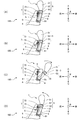
- FIG. 2 is an explanatory diagram showing a moving process of the mobile headrest 1.
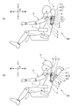
- 3 is a schematic view of the seat 100 on which the worker D is seated, and FIG.
- 3A is a side view of a partial cross section of the seat 100 in a state where the movable headrest 1 is disposed at the use position.
- (B) is a side view of a partial cross section of the seat 100 in a state where the mobile headrest 1 is disposed at the retracted position.
- the seat 100 includes a movable headrest 1, a seating surface 2, an armrest 3, and a backrest 4.
- the seat 100 in this embodiment is shown as a seat installed in the cab of the rough terrain crane.
- a rough terrain crane performs a lifting operation of a load
- an operator who sits on the seat 100 and performs an operation related to the lifting operation needs to proceed while visually checking the lifting state and the like.
- the seat 100 is an example of a seat in the present invention.
- the mobile headrest according to the present invention can be applied to a seat of a mobile crane such as a rough terrain crane that performs operations related to lifting and transporting various loads at the driver's seat.
- a mobile crane such as a rough terrain crane that performs operations related to lifting and transporting various loads at the driver's seat.
- the present invention is not limited to a work vehicle in which operations related to traveling and operations related to various operations are performed in the same driver's seat, and a driver's seat for traveling such as a truck crane and a driver's seat for working are provided separately. It can also be applied to existing work vehicles.
- the present invention can also be applied to a work vehicle that can perform excavation work or the like, such as a hydraulic excavator.
- the seat surface 2 is a part where the operator D shown in FIG.
- the backrest 4 is a part that extends upward from the rear edge of the seating surface 2 and can be leaned against the operator D against the back.
- the armrest 3 is a rod-like member that protrudes forward one by one from the left and right sides at an appropriate height of the backrest 4, and the operator D can place an upper limb such as an elbow.
- the movable headrest 1 includes a headrest body 5, a first rotation shaft 6, and a holding member 7.
- the headrest body 5 is a member provided on the upper portion of the seat 100, and includes a contact portion 51, two insertion shafts 52, and a base portion 53.
- the headrest main body 5 shown to FIG. 1 (A) and FIG. 1 (B) is arrange
- FIG. The headrest body 5 is an example of a headrest body in the present invention.
- the contact portion 51 is a portion where the back head of the operator D can contact when the headrest body 5 is disposed at the use position.
- the contact portion 51 is disposed so as to protrude upward from the upper portion of the backrest 4.
- the insertion shaft 52 is a rod-shaped member that protrudes from the contact portion 51.
- Two insertion shafts 52 are provided and arranged so as to be parallel to each other. In a state where the headrest body 5 is disposed at the use position, the insertion shaft 52 extends downward from the contact portion 51 as shown in FIGS. 1 (A) and 1 (B).
- the insertion shaft 52 is fixed to the contact portion 51.
- the base 53 is a substantially plate-like member into which the two insertion shafts 52 are inserted.
- the base 53 has an insertion port into which the insertion shaft 52 can be inserted, and the insertion shaft 52 can be inserted and removed.
- the base portion 53 is disposed so as to be fitted into a notch portion 8 formed at an upper portion of the rear surface portion of the backrest 4 at a substantially central portion in the width direction of the seat 100.
- the notch 8 is a recess formed by notching a part of the backrest 4 and is open rearward and upward.
- the first rotation shaft 6 is a member that enables the headrest body 5 to rotate about the axis.
- the first rotation shaft 6 is a shaft body that extends along the width direction of the seat 100 and passes through the backrest 4 and the headrest body 5 of the seat 100.
- a bottom surface portion 81 is formed as a lower surface portion in the notch portion 8 in the backrest 4.
- the first rotation shaft 6 is disposed between the left and right side portions of the notch portion 8 in the vicinity of the bottom surface portion 81 and is disposed in the notch portion 8. It penetrates the vicinity of the lower end of the base 53 of the main body 5.
- the headrest body 5 is movable between a use position where the headrest body 5 can be used and a retracted position where the headrest body 5 is not used by a combination of the base 53, the first rotation shaft 6, the cutout portion 8, and the like.
- the first rotation shaft 6 is an example of a movable member and a rotation shaft in the present invention.
- a restricting portion 9 is formed as an inclined surface with respect to the horizontal plane behind the portion of the base 53 through which the first rotation shaft 6 penetrates.
- the restriction portion 9 and the bottom surface portion 81 are portions that determine the posture of the headrest body 5 when the headrest body 5 is disposed at the retracted position. The restricting portion 9 and the bottom portion 81 will be described later together with the description of the movement mode with reference to FIG.
- the holding member 7 is a member that holds the headrest body 5 in the use position and can release the holding state, and includes a release lever 71 and a second rotation shaft. 72 and a locking claw 73. Note that the holding member 7 shown in FIGS. 1A and 1B holds the headrest body 5 in the use position.
- the holding member 7 is an example of a holding member in the present invention.
- the release lever 71 is a substantially bar-like portion disposed in the vicinity of the left side surface portion of the backrest 4, and is operated by being gripped by an operator when releasing the holding state of the headrest body 5.
- the second rotation shaft 72 is a shaft body that is inserted from the left side of the backrest 4 to the cutout portion 8, and is a member that can rotate around the long axis.
- the locking claw 73 is a member that can be locked to the fixed claw 10 that is fixedly provided on the left side of the base 53 of the headrest body 5.
- the locking claw 73 holds the headrest body 5 by locking with the fixed claw 10.
- the locking claw 73 and the fixing claw 10 are both hook-shaped members, and the hook portions are engaged with each other and locked.
- a release lever 71 is fixedly attached to one end of the second rotating shaft 72, and a locking claw 73 is fixedly attached to the other end. Therefore, when the release lever 71 is rotated about the axis of the second rotation shaft 72, the locking claw 73 is also rotated.
- the holding member 7 is held by attaching the biasing member S to the peripheral portion of the second rotating shaft 72 or the locking claw 73. Even if the member 7 is rotated, if the action of the stress for rotation is released, the posture shown in FIGS. 1A and 1B is restored by the biasing force of the biasing member S. Yes.
- the urging member S employs a torsion spring, and is fixed so that one end thereof is wound around the locking claw 73, and the spiral portion is disposed along the peripheral surface of the second rotation shaft 72. The other end is fixed to the backrest 4. Thus, once the locking claw 73 is locked with respect to the fixed claw 10, the locking state is maintained by the urging force of the urging member S.
- FIG. 2 (A) is the same as the state shown in FIG. 1 (B), and the headrest body 5 is arranged at the use position. Further, since the locking claw 73 is locked to the fixed claw 10, the headrest body 5 is held at the use position.
- the head D When the head D is seated on the seat 100 as shown in FIG. 3A when the headrest body 5 is disposed at the use position, the back of the head of the worker D abuts against the contact portion 51 of the headrest body 5. Is possible. That is, the operator D can use the headrest body 5 by placing the back head on the contact portion 51 of the headrest body 5.
- the worker D can perform a driving operation without wearing a helmet H, which will be described later, as shown in FIG. .
- the helmet H is basically not often worn when the work vehicle is traveling, there is no problem even if the headrest body 5 is disposed at the use position.
- the operator D may carry out a driving operation by placing the back of the head on the contact portion 51 of the headrest body 5, so that the headrest body 5 is disposed at the use position (FIG. 3A). ) Is preferable when the work vehicle is traveling.
- the release lever 71 of the holding member 7 is raised and moved forward.
- the second rotation shaft 72 attached to one end of the release lever 71 rotates.
- the locking claw 73 fixedly attached to the other end of the second rotation shaft 72 rotates.
- the locking claw 73 and the fixed claw 10 which are in the locked state shown in FIG.
- the locked state is released, and as a result, the holding state of the headrest body 5 by the holding member 7 is released.
- the headrest body 5 When the holding state of the headrest body 5 is released, the headrest body 5 becomes movable by the first rotating shaft 6 that is a movable member. When the headrest body 5 is pressed rearward while the holding state is released, the headrest body 5 rotates so as to fall backward about the first rotation shaft 6 as shown in FIG. .
- the upper portion of the base 53 in the state where it is disposed at the use position can be inclined further rearward than in the present embodiment. As a result, when the holding state of the headrest body 5 is released by rotating the release lever 71, the headrest body 5 falls back due to its own weight without pressing the headrest body 5 backward. Therefore, the process of moving the headrest body 5 from the use position to the retracted position can be further simplified.
- the headrest body 5 shown in FIG. 2 (C) is disposed at the retracted position.
- the helmet H is brought into contact with the contact portion 51 of the headrest body 5. Does not touch. That is, since the contact portion 51 of the headrest body 5 in the retracted position does not contact the helmet H, the operator D is not using the headrest body 5.
- a situation where the operator D moves the headrest body 5 to the retracted position for example, a situation where the operator D wears the helmet H and performs an operation related to the operation can be cited.
- an operation related to the work performed by the worker D it is assumed that the seat 100 in the present embodiment is installed in the cab of the rough terrain crane. Can be mentioned.
- operations related to the work performed by the worker D can also include lifting work and transport work, and operations when applied to a hydraulic excavator.
- the headrest main body 5 can be rotated until the restriction portion 9 of the headrest main body 5 and the bottom surface portion 81 of the notch portion 8 come into contact with each other.
- the rotation range of the headrest body 5 is determined in accordance with the shape, angle, and dimensions of the restricting portion 9 and the bottom surface portion 81, the size of the empty area in the cab, and the like.
- the rotation range of the headrest body 5 is preferably set so that it can be rotated at least until the helmet H of the operator D does not contact the contact portion 51 of the headrest body 5.
- the headrest body 5 is moved forward as shown in FIG. As a result, the headrest body 5 is pivoted so as to rise forward about the first pivot shaft 6, and the locking claw 73 is locked again with respect to the fixed claw 10.
- the helmet H When the operator D performs an operation related to an appropriate operation while sitting on the seat, the helmet H is often required to be worn. Since the helmet H protrudes further rearward than the rear head of the worker D, the rear part of the helmet H comes into contact with the headrest body 5 arranged at the use position, that is, the existing headrest. Furthermore, when performing an operation to be performed while visually confirming the upper side such as lifting work, the back of the head of the worker D and the helmet H are pushed further back, so that the helmet H strongly contacts the existing headrest, so that the worker Helmet H was displaced in front of D's head, and it was difficult to secure visibility and continue the work.
- the mobile headrest 1 in the seat 100 is movable to the retracted position by rotating the headrest body 5 held in the use position backward when the held state is released.
- the helmet H does not come into contact with the contact portion 51 of the headrest body 5. Therefore, this embodiment can implement
- the headrest body when the present invention is applied to a work vehicle in which a driving driver's seat and a working driver's seat are separately provided, the headrest body is in a traveling state or in a state where an operator does not wear a helmet without performing a work.
- the headrest body can be moved to the retracted position by a simple work in a state in which the headrest body is held at the use position and an operation related to the work is performed.
- this embodiment when this embodiment is applied to a work vehicle, it is possible to use some vacant areas around the seat of an existing work vehicle, so that it is not necessary to change the design significantly.
- the operation of placing the headrest body 5 in the retracted position it is only necessary to rotate the release lever 71 and push the headrest body 5 backward, so that a large work area is unnecessary. Furthermore, it is preferable because the work that has been conventionally performed, such as the work of removing the headrest body 5, the work of installing the removed headrest body 5 in the storage area, and the work of exchanging the traveling headrest with the work headrest, is not necessary.
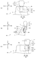
- FIG. 4 is a schematic view showing a seat 101 having a mobile headrest 11 according to another embodiment of the present invention
- FIG. 4 (A) is a front view of the seat 101
- FIG. 4 (B) is FIG. 4A is a side view of the seat 101 shown in FIG. 4A
- FIG. 4C is a front view showing a state in which the movable headrest 11 of the seat 101 shown in FIG.
- the difference between the embodiment shown in FIG. 4 and the embodiment shown in FIGS. 1 to 3 is a movable member, a holding member, a notch, and a moving form. Except for this difference, the same members as those of the embodiment shown in FIGS. 1 to 3 are used, and therefore, common members are denoted by the same reference numerals and detailed description thereof is omitted.
- a sliding member 60 is provided as a movable member. Further, a rotation stopper 70 is provided as a holding member. As shown in FIG. 4, the notch 80 is formed such that the left side of the notch 8 is largely notched to the side surface of the backrest 4. Furthermore, the movement form of the headrest main body 5 in the embodiment shown in FIG. 4 is a form that slides along the width direction of the seat 101.
- the sliding member 60 includes a guide member 601 and a sliding member 602. Further, the bottom surface portion 801 of the notch 80 extends from the vicinity of the right side of the lower end portion of the headrest body 5 to the side surface portion of the backrest 4 in the width direction of the seat 101 as a substantially horizontal plane.
- the guide member 601 is a long member that extends over substantially the entire area of the bottom surface portion 801 in the width direction of the seat 101. In particular, as shown in FIG. 4B, a concave groove is formed on the side surface of the guide member 601. The extension length of the guide member 601 determines the range in which the headrest body 5 moves.
- the sliding member 602 is a member that is provided on the lower surface portion of the base 53 in the headrest body 5 and that can engage and slide with respect to the guide member 601. Specifically, the sliding member 602 is disposed so as to cover a part of the upper surface portion and the side surface portion of the guide member 601 and can be engaged with a groove portion formed on the side surface portion of the guide member 601. Have The sliding member 602 can slide smoothly with respect to the guide member 601 along the extending direction of the guide member 601.
- the sliding member 602 has a circulation type bearing that enables linear motion at a contact portion with the guide member 601, thereby enabling smooth sliding with respect to the guide member 601.
- a so-called linear guide is preferably used as the sliding member 60 having the guide member 601 and the sliding member 602, for example.
- the rotation stopper 70 is a member that can switch a portion that presses the headrest body 5 by rotation, and includes an outer stopper 701, a rotation shaft 702, and an inner stopper 703.
- the rotation stopper 70 is a member in which members similar to the release lever 71 of the holding member 7 are fixedly attached to both ends of the rotation shaft 702. That is, the outer stopper 701 and the inner stopper 703 differ only in the mounting angle with respect to the rotating shaft 702 as shown in FIG. 4B, and both members are substantially rod-shaped members that can be gripped by the operator. is there. Since the urging member S described above is not attached to the rotation shaft 702, when the rotation stopper 70 is rotated by gripping the outer stopper 701, the rotation stopper 70 maintains the rotated posture. It has become.
- the holding of the headrest body 5 in the use position is realized by the inner stopper 703 coming into contact with the left side surface portion of the base portion 53 as shown in FIG. In this state, the inner stopper 703 presses the headrest body 5 from the left side, so that the headrest body 5 prevents the seat 101 from moving in the width direction, particularly to the left side.
- the outer stopper 701 is rotated around the rotation shaft 702 in the direction of the arrow shown in FIG.
- the inner stopper 703 is also rotated.
- the inner stopper 703 does not contact the side of the base 53 in the headrest body 5. Therefore, the holding state of the headrest body 5 is released.
- the retracted position of the headrest body 5 in the embodiment shown in FIG. 4 is a position where the outer stopper 701 contacts the left side surface portion of the base portion 53.
- the outer stopper 701 prevents the headrest body 5 from further moving in the width direction of the seat 101, in particular, falling off to the left side by pressing the headrest body 5 from the left side. .
- the outer stopper 701 or the inner stopper 703 is arranged on the track of the base 53 along the guide member 601, before and after the rotation of the rotation stopper 70. .
- the pressing function can be exhibited by the outer stopper 701 or the inner stopper 703.
- the helmet H as shown in FIG. 3 when the headrest body 5 moves to the retracted position, the helmet H as shown in FIG. 3 is moved to a position where the contact portion 51 is removed from the central portion in the width direction of the seat 101.
- the contact portion 51 of the headrest body 5 is not contacted. Therefore, the embodiment shown in FIG. 4 can realize a state where the headrest body 5 can be used for safe traveling and a state where the contact of the headrest body 5 with the helmet H is eliminated by simple work.
- the embodiment shown in FIG. 4 when the embodiment shown in FIG. 4 is applied to a work vehicle, it is possible to use some vacant areas around the seats of existing work vehicles, so there is no need to change the design significantly.
- the first rotation shaft 6 is provided without providing the base 53 and the notch 8 described above. Only the contact portion 51 may be rotated rearward by changing the position to a position close to the lower portion of the contact portion 51.
- the upper and lower positions of the locking claw 73 and the fixing claw 10 shown in FIGS. 1 to 3 may be replaced.
- the claws may be engaged with each other so that the locking claw 73 covers from above the fixed claw 10.
- the release lever 71 is rotated to release the holding state of the headrest body 5, and when the headrest body 5 is further moved to the retracted position, the release lever held by the operator D It is possible to return to the initial position by the weight of the locking claw 73 simply by releasing 71. Thereby, the biasing member S mentioned above becomes unnecessary.
- SYMBOLS 1 and 11 Mobile headrest, 100 and 101: Seat, 2: Seat surface, 3: Armrest, 4: Backrest, 5: Headrest main body, 51: Contact part, 52: Insertion shaft, 53: Base, 6: First rotating shaft, 60: sliding member, 601: guide member, 602: sliding member, 7: holding member, 71: release lever, 72: second rotating shaft, 73: locking claw, 70: rotating Stopper, 701: Outer stopper, 702: Rotating shaft, 703: Inner stopper, 8 and 80: Notch part, 81 and 801: Bottom part, 9: Restricting part, 10: Fixed claw, D: Worker, H: Helmet , S: biasing member
Landscapes
- Engineering & Computer Science (AREA)
- Aviation & Aerospace Engineering (AREA)
- Transportation (AREA)
- Mechanical Engineering (AREA)
- Seats For Vehicles (AREA)
Abstract
作業に係る操作を行う運転席を備えた作業車において、作業者が作業時にヘルメットを装着しても、ヘルメットが接触しない移動式ヘッドレストを提供すること。 移動式ヘッドレスト1は、作業車の座席100に設けられるヘッドレスト本体5と、ヘッドレスト本体5を使用可能な使用位置と、使用しない退避位置との間で、ヘッドレスト本体5を移動可能にする第1回動軸6と、ヘッドレスト本体5を使用位置に保持し、保持状態が解除可能な保持部材7と、を備える。
Description
本発明は、移動式ヘッドレストに関し、特に作業車の運転席で操作を行う際に作業者がヘルメットを装着しても、ヘルメットが接触しない移動式ヘッドレストに関する。
作業に係る操作を運転席で行う作業車において、作業時にはヘルメットの装着が作業者に課せられる場合がある。
しかしながら、ヘルメットの装着が課せられた場合に、ヘルメットがヘッドレストに接触して邪魔になり易いので、従来では作業時にヘッドレストを取外して、運転室内の他の領域にヘッドレストを保管しておくことが多かった。
しかしながら、ヘルメットの装着が課せられた場合に、ヘルメットがヘッドレストに接触して邪魔になり易いので、従来では作業時にヘッドレストを取外して、運転室内の他の領域にヘッドレストを保管しておくことが多かった。
更に従来では、例えば作業時に走行運転用ヘッドレストから作業用ヘッドレストに交換する自走式クレーンの運転室用座席が知られている(特許文献1参照。)。
しかしながら、従来においてはヘッドレストを取外す作業、他の保管領域に設置する作業、及び、走行用ヘッドレストと作業用ヘッドレストとの交換作業が必要であり、各種作業機器を用いる作業の前段階が常に煩雑となっていた。
更に、作業車の運転室の車内空間は、作業者の乗降車、走行に係る操作、及び作業に係る操作等の最低限の動作が可能な程度の領域が確保されているだけであるという場合が多く、上述の様々な作業を行う領域及び取外したヘッドレストを保管する領域を確保することが困難であった。
よって、本発明が解決しようとする課題は、作業に係る操作を行う運転席を備えた作業車において、作業者が作業時にヘルメットを装着しても、ヘルメットが接触しない移動式ヘッドレストを提供することである。
前記課題を解決するための手段として、本発明に係る移動式ヘッドレストは、作業車の座席に設けられるヘッドレスト本体と、前記ヘッドレスト本体を使用可能な使用位置と、使用しない退避位置との間で、前記ヘッドレスト本体を移動可能にする可動部材と、前記ヘッドレスト本体を前記使用位置に保持し、保持状態が解除可能な保持部材と、を備える。
また、本発明に係る移動式ヘッドレストの前記退避位置は、前記使用位置に対して後方又は前記座席の幅方向の外側であるのが好ましい。
また、本発明に係る移動式ヘッドレストの前記退避位置は、前記使用位置に対して後方であり、前記可動部材は、前記座席の幅方向に沿って延在し、前記座席のバックレストと前記ヘッドレスト本体と挿通する回動軸を有し、前記保持部材は、係止により前記ヘッドレスト本体を保持する係止ツメを有し、前記ヘッドレスト本体は、係止ツメによる係止が解除されると、前記回動軸を中心として後方に回動可能になるのが好ましい。
本発明によると、ヘッドレスト本体の使用位置への保持状態が解除されると、ヘッドレスト本体が可動部材により使用位置から退避位置に移動可能になる。これにより、作業に係る操作を行う運転席を備えた作業車において、作業者が作業時にヘルメットを装着しても、ヘッドレスト本体を退避位置に移動させておくことによって、ヘルメットがヘッドレスト本体に接触せず、ヘッドレスト本体の取外し作業及び交換作業の必要性が生じない移動式ヘッドレストを提供することができる。
また、操作に係る操作を行う運転席は通常、座席の後方及び座席幅方向の外側に若干の空き領域があることが多い。よって、本発明の好ましい形態によると、このような運転席で空き領域に退避位置を設定することによって、既存の作業車の運転席を大幅に設計変更する必要の無い移動式ヘッドレストを提供することができる。
本発明の他の好ましい形態によると、様々な作業車の運転席において共通して若干の空き領域があることの多い座席の後方に退避位置を設定し、係止ツメの係止状態を解除した上でヘッドレスト本体を後方に倒すだけで、ヘッドレスト本体がヘルメットに接触しなくなる。また、使用位置に戻す作業が後方から前方に戻すだけで完了する。したがって、作業車が安全に走行可能な状態又は作業を行わない状態と、ヘルメットに対するヘッドレスト本体の接触が解消された状態とを、簡便な作業によって実現可能な移動式ヘッドレストを提供することができる。
以下に、本発明に係るリフト装置について、図面を参照しつつ説明する。
まず本発明の一実施形態に係る移動式ヘッドレスト1の概要について図1~図3を参照しつつ説明する。図1は本発明の一実施形態である移動式ヘッドレスト1を備えた座席100を示す概略図であり、図1(A)は座席100の正面図であり、図1(B)は図1(A)の座席100の一部断面の側面図である。図2は、移動式ヘッドレスト1の移動工程を示す説明図である。図3は作業者Dが着座した座席100の概略図であり、図3(A)は移動式ヘッドレスト1が使用位置に配置された状態の座席100の一部断面の側面図であり、図3(B)は移動式ヘッドレスト1が退避位置に配置された状態の座席100の一部断面の側面図である。
まず本発明の一実施形態に係る移動式ヘッドレスト1の概要について図1~図3を参照しつつ説明する。図1は本発明の一実施形態である移動式ヘッドレスト1を備えた座席100を示す概略図であり、図1(A)は座席100の正面図であり、図1(B)は図1(A)の座席100の一部断面の側面図である。図2は、移動式ヘッドレスト1の移動工程を示す説明図である。図3は作業者Dが着座した座席100の概略図であり、図3(A)は移動式ヘッドレスト1が使用位置に配置された状態の座席100の一部断面の側面図であり、図3(B)は移動式ヘッドレスト1が退避位置に配置された状態の座席100の一部断面の側面図である。
図1(A)及び図1(B)に示すように、座席100は、移動式ヘッドレスト1と、座面2と、アームレスト3と、バックレスト4とを備えている。本実施形態における座席100は、ラフテレーンクレーンの運転室内に設置される座席として示している。ラフテレーンクレーンが荷物の揚重作業を行う際には、座席100に着座して揚重作業に係る操作を行う作業者が揚重状況等を確認するために上方を視認しつつ作業を進める必要がある。
なお、座席100は、本発明における座席の一例である。
なお、座席100は、本発明における座席の一例である。
本発明に係る移動式ヘッドレストは、種々の荷物の揚重作業及び搬送作業に係る操作を運転席で行う作業車、例えばラフテレーンクレーン等の移動式クレーンの座席に適用することができる。なお、本発明は、走行に係る操作と各種作業に係る操作とを同一の運転席で行う作業車に限られず、トラッククレーン等の走行用の運転席と作業用の運転席とが別に設けられている作業車にも適用することができる。更に本発明は、掘削作業等を行うことのできる作業車、例えば油圧ショベル等にも適用することができる。
座面2は、図3(A)に示す作業者Dが着座する部位である。バックレスト4は、座面2の後端縁部から上方に延在し、作業者Dが背中を当てて、もたれかかることのできる部位である。アームレスト3は、バックレスト4の適宜の高さにおいて左右両側から1本ずつ前方に突出する棒状部材であり、作業者Dが肘等の上肢を載せることができる。
移動式ヘッドレスト1は、ヘッドレスト本体5と、第1回動軸6と、保持部材7とを備える。
ヘッドレスト本体5は、座席100の上部に設けられる部材であり、当接部51、2本の挿入軸52、及び基部53を有する。なお、図1(A)及び図1(B)に示すヘッドレスト本体5は、ヘッドレスト本体5を使用可能な使用位置に配置されている。
ヘッドレスト本体5は、本発明におけるヘッドレスト本体の一例である。
ヘッドレスト本体5は、本発明におけるヘッドレスト本体の一例である。
当接部51は、図3(A)に示すように、ヘッドレスト本体5が使用位置に配置されているときに作業者Dの後頭部が当接可能な部位である。当接部51はバックレスト4の上部から上方に突出して配置される。
挿入軸52は、当接部51から突出する棒状部材である。挿入軸52は2本設けられ、相互に平行となるように配置されている。ヘッドレスト本体5が使用位置に配置されている状態では、図1(A)及び図1(B)に示すように、挿入軸52は当接部51から下方に延在している。挿入軸52は当接部51に固定されている。
基部53は、2本の挿入軸52が挿入される略板状部材である。基部53は、挿入軸52が挿入可能な挿入口を有し、挿入軸52が挿抜自在になっている。
挿入軸52は、当接部51から突出する棒状部材である。挿入軸52は2本設けられ、相互に平行となるように配置されている。ヘッドレスト本体5が使用位置に配置されている状態では、図1(A)及び図1(B)に示すように、挿入軸52は当接部51から下方に延在している。挿入軸52は当接部51に固定されている。
基部53は、2本の挿入軸52が挿入される略板状部材である。基部53は、挿入軸52が挿入可能な挿入口を有し、挿入軸52が挿抜自在になっている。
基部53は、座席100の幅方向略中央部においてバックレスト4の後面部の上部に形成された切欠部8に嵌め込まれるように配置されている。切欠部8は、バックレスト4の一部を切り欠いて形成される凹部であり、後方及び上方に開放されている。
第1回動軸6は、その軸線を中心にしてヘッドレスト本体5を回動可能にする部材である。第1回動軸6は、座席100の幅方向に沿って延在し、座席100のバックレスト4とヘッドレスト本体5とを挿通する軸体である。図1(B)に示すように、バックレスト4における切欠部8には、下面部分として底面部81が形成されている。図1(A)に示すように、第1回動軸6は、底面部81近傍において切欠部8の左右両面部の間に渡されて配置され、かつ、切欠部8内に配置されるヘッドレスト本体5の基部53の下端近傍部位を貫通している。
基部53、第1回動軸6及び切欠部8等の組合せによって、ヘッドレスト本体5を使用可能な使用位置と、使用しない退避位置との間で、ヘッドレスト本体5が移動可能になっている。
第1回動軸6は、本発明における可動部材及び回動軸の一例である。
基部53、第1回動軸6及び切欠部8等の組合せによって、ヘッドレスト本体5を使用可能な使用位置と、使用しない退避位置との間で、ヘッドレスト本体5が移動可能になっている。
第1回動軸6は、本発明における可動部材及び回動軸の一例である。
また、図1(B)に示すように、基部53の第1回動軸6が貫通している部位の後方には、規制部9が水平面に対する傾斜面として形成されている。規制部9及び底面部81は、ヘッドレスト本体5が退避位置に配置された場合に、ヘッドレスト本体5の姿勢を決定する部位である。規制部9及び底面部81については、図2を参照する移動形態の説明と共に後述する。
保持部材7は、図1(A)及び図1(B)に示すように、ヘッドレスト本体5を使用位置に保持し、保持状態が解除可能な部材であり、解除レバー71、第2回動軸72、及び係止ツメ73を有する。なお、図1(A)及び図1(B)に示す保持部材7は、ヘッドレスト本体5を使用位置に保持している。
保持部材7は、本発明における保持部材の一例である。
保持部材7は、本発明における保持部材の一例である。
解除レバー71は、バックレスト4の左側面部近傍に配置される略棒状部位であり、ヘッドレスト本体5の保持状態を解除する際に作業者が把持して操作される。
第2回動軸72は、バックレスト4の左側から切欠部8まで挿通する軸体であり、長軸を中心にして回動可能な部材である。
係止ツメ73は、ヘッドレスト本体5の基部53の左側において固定的に付設される固定ツメ10に対して係止可能な部材である。係止ツメ73は、固定ツメ10に対する係止によってヘッドレスト本体5を保持する。係止ツメ73及び固定ツメ10はいずれも鉤状部材であり、鉤部分が相互に咬み合って係止状態となっている。
第2回動軸72の一端部に解除レバー71が固定的に取付けられ、他端部に係止ツメ73が固定的に取付けられている。よって、解除レバー71を第2回動軸72の軸線を中心にして回動させると、係止ツメ73も回動する。
第2回動軸72は、バックレスト4の左側から切欠部8まで挿通する軸体であり、長軸を中心にして回動可能な部材である。
係止ツメ73は、ヘッドレスト本体5の基部53の左側において固定的に付設される固定ツメ10に対して係止可能な部材である。係止ツメ73は、固定ツメ10に対する係止によってヘッドレスト本体5を保持する。係止ツメ73及び固定ツメ10はいずれも鉤状部材であり、鉤部分が相互に咬み合って係止状態となっている。
第2回動軸72の一端部に解除レバー71が固定的に取付けられ、他端部に係止ツメ73が固定的に取付けられている。よって、解除レバー71を第2回動軸72の軸線を中心にして回動させると、係止ツメ73も回動する。
なお、図1(A)及び図1(B)に示すように、保持部材7は、第2回動軸72又は係止ツメ73の周辺部位に付勢部材Sが付設されることによって、保持部材7が回動しても回動のための応力の作用を解除すれば、付勢部材Sの付勢力によって図1(A)及び図1(B)に示す姿勢に復元するようになっている。本実施形態において付勢部材Sは、トーションバネを採用しており、一端部が係止ツメ73に巻き付けるようにして固定され、螺旋部分が第2回動軸72の周面に沿って配置され、他端部をバックレスト4に固定されている。これにより、係止ツメ73が固定ツメ10に対して一旦係止状態となれば、付勢部材Sの付勢力によって該係止状態を維持することとなる。
次に、図2及び図3を参照しつつ、移動式ヘッドレスト1におけるヘッドレスト本体5の移動形態について説明する。
図2(A)は図1(B)に示した状態と同状態であり、ヘッドレスト本体5が使用位置に配置されている。また、係止ツメ73が固定ツメ10に対して係止されていることによって、ヘッドレスト本体5が使用位置に保持されている。
ヘッドレスト本体5が使用位置に配置されているときに、図3(A)に示すように座席100に作業者Dが着座すると、作業者Dの後頭部がヘッドレスト本体5の当接部51に当接可能である。つまり、作業者Dは、ヘッドレスト本体5の当接部51に後頭部をもたせかけることにより、ヘッドレスト本体5を使用することができる。
作業者Dがヘッドレスト本体5を使用する状況としては、例えば作業者Dは図3(A)に示すように後述のヘルメットHを装着せず、走行に係る操作を行う状況等を挙げることができる。作業車の走行時には基本的にヘルメットHは装着しないことが多いので、ヘッドレスト本体5が使用位置に配置されていても問題は生じない。更に、長時間の走行時には、作業者Dがヘッドレスト本体5の当接部51に後頭部をもたせかけて走行運転をすることもあるので、ヘッドレスト本体5が使用位置に配置されている図3(A)に示す状態が作業車の走行時に好適である。
次いで移動式ヘッドレスト1におけるヘッドレスト本体5を移動させるには、先ず図2(B)に示すように、保持部材7の解除レバー71を前方に起こすようにして回動させる。解除レバー71が回動すると、解除レバー71が一端部に取付けられている第2回動軸72が回動する。第2回動軸72が回動すると、第2回動軸72の他端部に固定的に取付けられている係止ツメ73が回動する。係止ツメ73が回動すると、図2(A)に示す係止状態であった係止ツメ73と固定ツメ10とは離れる。これにより係止状態が解除され、結果として保持部材7によるヘッドレスト本体5の保持状態が解除されることとなる。
ヘッドレスト本体5の保持状態が解除されることによって、ヘッドレスト本体5は可動部材である第1回動軸6によって移動可能な状態となる。保持状態が解除されている間にヘッドレスト本体5を後方に押圧すると、図2(C)に示すように、ヘッドレスト本体5が第1回動軸6を中心にして後方に倒れるように回動する。
なお、本発明においては、使用位置に配置された状態での基部53の上部を本実施形態よりも更に後方に傾斜させた姿勢にすることもできる。これにより、解除レバー71を回動させることによってヘッドレスト本体5の保持状態が解除されたときに、ヘッドレスト本体5を後方に押圧しなくともヘッドレスト本体5の自重で後方に倒れるようになる。よって、ヘッドレスト本体5を使用位置から退避位置まで移動させる工程について、より一層簡略化を図ることができる。
なお、本発明においては、使用位置に配置された状態での基部53の上部を本実施形態よりも更に後方に傾斜させた姿勢にすることもできる。これにより、解除レバー71を回動させることによってヘッドレスト本体5の保持状態が解除されたときに、ヘッドレスト本体5を後方に押圧しなくともヘッドレスト本体5の自重で後方に倒れるようになる。よって、ヘッドレスト本体5を使用位置から退避位置まで移動させる工程について、より一層簡略化を図ることができる。
図2(C)に示すヘッドレスト本体5は退避位置に配置されている。ヘッドレスト本体5が退避位置に配置されているときに、図3(B)に示すように座席100にヘルメットHを装着した作業者Dが着座すると、ヘルメットHがヘッドレスト本体5の当接部51に当接しない。つまり、退避位置にあるヘッドレスト本体5の当接部51はヘルメットHに接触しないので、作業者Dはヘッドレスト本体5を使用しない状態である。
作業者Dがヘッドレスト本体5を退避位置に移動させる状況としては、例えば作業者DがヘルメットHを装着し、作業に係る操作を行う状況等を挙げることができる。作業者Dが行う作業に係る操作としては、本実施形態における座席100はラフテレーンクレーンの運転室に設置されることを想定しているので、例えば種々の荷物の揚重作業及び搬送作業等を挙げることができる。
なお、本発明がラフテレーンクレーン以外のクレーン車に適用される場合に作業者Dが行う作業に係る操作も揚重作業及び搬送作業を挙げることができ、油圧ショベルに適用される場合の操作としては、例えば掘削作業等を挙げることができる。
なお、本発明がラフテレーンクレーン以外のクレーン車に適用される場合に作業者Dが行う作業に係る操作も揚重作業及び搬送作業を挙げることができ、油圧ショベルに適用される場合の操作としては、例えば掘削作業等を挙げることができる。
ここで、ヘッドレスト本体5は、ヘッドレスト本体5の規制部9と切欠部8の底面部81とが当接するまで回動可能である。規制部9及び底面部81の形状、角度及び寸法、運転室内の空き領域の大きさ等に応じて、ヘッドレスト本体5の回動範囲が決定される。ヘッドレスト本体5の回動範囲は、作業者DのヘルメットHがヘッドレスト本体5の当接部51に接触しない位置までは少なくとも回動可能に設定するのが良い。
続いて、ヘッドレスト本体5を退避位置から使用位置に戻すには、図2(D)に示すように、ヘッドレスト本体5を前方に引き起こす。これによって、ヘッドレスト本体5が第1回動軸6を中心にして前方に起き上がるように回動し、係止ツメ73が固定ツメ10に対して再度係止状態になる。
係止ツメ73が固定ツメ10に対して再度係止状態になると、次に解除レバー71が操作されて係止状態が再度解除されるまで、第1回動軸6に作用する付勢部材Sの付勢力によって係止状態が維持される。
作業者Dが座席に着座した状態で適宜の作業に係る操作を行う場合、ヘルメットHの装着義務を課せられていることが多い。ヘルメットHは作業者Dの後頭部よりも更に後方に突出するので、使用位置に配置されるヘッドレスト本体5、つまり既存のヘッドレストにヘルメットHの後部が接触してしまう。更に、揚重作業等の上方を視認しつつ進める作業を行う場合、作業者Dの後頭部及びヘルメットHがより一層後方に押し出されるので、既存のヘッドレストにヘルメットHが強く接触することによって、作業者Dの頭部前方にヘルメットHがズレてしまい、視界の確保及び作業の継続が困難であった。
そこで従来では、例えば作業中だけ当接部51と挿入軸52とをバックレスト4から抜去して保管しておき、走行時に再度当接部51及び挿入軸52をバックレスト4に取付ける方法、又は、走行用ヘッドレストと作業用ヘッドレストとを適宜に交換する方法等を採ることによって、ヘルメットHとヘッドレストとの接触を防いでいた。
しかしながら、作業車では車内空間を広く確保されていることが少ないので、ヘッドレストを取外す作業領域、取外したヘッドレストの保管領域、及び、走行用ヘッドレストと作業用ヘッドレストとを交換する作業領域等を確保することは困難であった。
なお、座席100の後方及び座席100の幅方向外側には、上記保管領域及び上記交換作業領域にはなりにくいが、若干の空き領域があることが多い。
なお、座席100の後方及び座席100の幅方向外側には、上記保管領域及び上記交換作業領域にはなりにくいが、若干の空き領域があることが多い。
これに鑑みて、座席100における移動式ヘッドレスト1は、使用位置に保持されたヘッドレスト本体5が、保持状態を解除されると後方に回動することで、退避位置に移動可能になっている。図2(C)及び図3(B)に示す退避位置までヘッドレスト本体5を移動させることによって、ヘルメットHがヘッドレスト本体5の当接部51に接触しなくなる。
したがって本実施形態は、ヘッドレスト本体5を使用して安全走行が可能な状態と、ヘルメットHに対するヘッドレスト本体5の接触が解消された状態とを、簡便な作業によって実現可能である。なお、走行用の運転席と作業用の運転席とが別に設けられる作業車に対して本発明を適用する場合に、走行状態又は作業を行わずに作業者がヘルメットを着用しない状態ではヘッドレスト本体を使用位置に保持しておき、作業に係る操作を行う状態ではヘッドレスト本体を退避位置まで簡便な作業によって移動させることができる。
また、本実施形態を作業車に適用する場合に、既存の作業車の座席周辺にある若干の空き領域を利用することができるので、大幅に設計変更する必要が無い。
したがって本実施形態は、ヘッドレスト本体5を使用して安全走行が可能な状態と、ヘルメットHに対するヘッドレスト本体5の接触が解消された状態とを、簡便な作業によって実現可能である。なお、走行用の運転席と作業用の運転席とが別に設けられる作業車に対して本発明を適用する場合に、走行状態又は作業を行わずに作業者がヘルメットを着用しない状態ではヘッドレスト本体を使用位置に保持しておき、作業に係る操作を行う状態ではヘッドレスト本体を退避位置まで簡便な作業によって移動させることができる。
また、本実施形態を作業車に適用する場合に、既存の作業車の座席周辺にある若干の空き領域を利用することができるので、大幅に設計変更する必要が無い。
本実施形態においては、ヘッドレスト本体5を退避位置に配置する作業として、解除レバー71を回動させてヘッドレスト本体5を後方に押し倒すだけで済むので、大きな作業領域が不要である。更に、従来行っていた作業、例えばヘッドレスト本体5の取外し作業、取外したヘッドレスト本体5を保管領域に設置する作業、及び、走行用ヘッドレストと作業用ヘッドレストとの交換作業等が不要であるので好ましい。
次に、図1~図3に示した実施形態の変形例を図4に示す。
図4は本発明の他の実施形態である移動式ヘッドレスト11を備えた座席101を示す概略図であり、図4(A)は座席101の正面図であり、図4(B)は図4(A)に示す座席101の側面図であり、図4(C)は図4(A)に示す座席101の移動式ヘッドレスト11が移動した状態の正面図である。
図4は本発明の他の実施形態である移動式ヘッドレスト11を備えた座席101を示す概略図であり、図4(A)は座席101の正面図であり、図4(B)は図4(A)に示す座席101の側面図であり、図4(C)は図4(A)に示す座席101の移動式ヘッドレスト11が移動した状態の正面図である。
図4に示す実施形態と図1~図3に示した実施形態との相違点は、可動部材、保持部材、切欠部及び移動形態である。この相違点以外は、図1~図3に示した実施形態と同一部材を用いているので、共通する部材については同一の参照符号を付し、詳細な説明は省略する。
図4に示す実施形態においては、可動部材として滑動部材60を設けている。また、保持部材として、回動ストッパ70を設けている。図4に示すように、切欠部80は上記切欠部8よりも左側がバックレスト4の側面部まで大きく切り欠かれて形成されている。更に、図4に示す実施形態におけるヘッドレスト本体5の移動形態は、座席101の幅方向に沿ってスライドする形態である。
滑動部材60は、案内部材601と摺動部材602とを有する。また、切欠部80の底面部801は、座席101の幅方向において、ヘッドレスト本体5の下端部の右方近傍からバックレスト4の側面部に達するまで略水平面として延在している。
案内部材601は、座席101の幅方向において、底面部801の略全域に亘って延在する長尺状部材である。特に図4(B)に示すように、案内部材601の側面部には凹状の溝部が形成されている。案内部材601の延在長さは、ヘッドレスト本体5が移動する範囲を決定する。
摺動部材602は、ヘッドレスト本体5における基部53の下面部に設けられ、案内部材601に対する係合及び摺動が可能な部材である。具体的には、摺動部材602は、案内部材601の上面部及び側面部の一部を覆うように配置され、案内部材601の側面部に形成される溝部に対して係合可能な凸部を有する。摺動部材602は案内部材601に対して案内部材601の延在方向に沿って円滑に摺動可能である。摺動部材602は案内部材601との接触部位において直線運動を可能にする循環型のベアリングを有することによって、案内部材601に対して円滑な摺動が可能になっている。
案内部材601及び摺動部材602を有する滑動部材60としては、例えばいわゆるリニアガイド等を用いるのが好ましい。
案内部材601は、座席101の幅方向において、底面部801の略全域に亘って延在する長尺状部材である。特に図4(B)に示すように、案内部材601の側面部には凹状の溝部が形成されている。案内部材601の延在長さは、ヘッドレスト本体5が移動する範囲を決定する。
摺動部材602は、ヘッドレスト本体5における基部53の下面部に設けられ、案内部材601に対する係合及び摺動が可能な部材である。具体的には、摺動部材602は、案内部材601の上面部及び側面部の一部を覆うように配置され、案内部材601の側面部に形成される溝部に対して係合可能な凸部を有する。摺動部材602は案内部材601に対して案内部材601の延在方向に沿って円滑に摺動可能である。摺動部材602は案内部材601との接触部位において直線運動を可能にする循環型のベアリングを有することによって、案内部材601に対して円滑な摺動が可能になっている。
案内部材601及び摺動部材602を有する滑動部材60としては、例えばいわゆるリニアガイド等を用いるのが好ましい。
回動ストッパ70は、回動によってヘッドレスト本体5を押さえる部位が切り換え可能な部材であり、外側ストッパ701、回動軸702、及び内側ストッパ703を有する。回動ストッパ70は、上記保持部材7の解除レバー71と同様の部材を回動軸702の両端に固定的に取付けた部材である。つまり、外側ストッパ701と内側ストッパ703とは、図4(B)に示すように回動軸702に対する取付角度が相違するだけであり、両部材共に作業者が把持可能な程度の略棒状部材である。
回動軸702には上述した付勢部材Sは付設されていないので、外側ストッパ701を把持して回動ストッパ70を回動させると、回動ストッパ70は回動させた姿勢を維持するようになっている。
回動軸702には上述した付勢部材Sは付設されていないので、外側ストッパ701を把持して回動ストッパ70を回動させると、回動ストッパ70は回動させた姿勢を維持するようになっている。
図4に示す実施形態において、ヘッドレスト本体5の使用位置への保持は、特に図4(A)に示すように、内側ストッパ703が基部53の左側面部に当接することによって実現している。この状態では、内側ストッパ703がヘッドレスト本体5を左側から押さえることによって、ヘッドレスト本体5が座席101の幅方向の移動、特に左側への移動を阻止している。
ここで、図4に示す実施形態におけるヘッドレスト本体5の移動について説明する。
図4に示す実施形態においてヘッドレスト本体5を移動させるには、先ず外側ストッパ701を、図4(B)に示す矢印の方向に回動軸702を中心として回動させる。外側ストッパ701を回動させると、内側ストッパ703も回動する。これにより、内側ストッパ703がヘッドレスト本体5における基部53の側方に当接しなくなる。よって、ヘッドレスト本体5の保持状態が解除される。
次いで、ヘッドレスト本体5を左方に押圧することによって、基部53の下方に設けられる滑動部材60の摺動部材602が案内部材601上を円滑に摺動する。これにより、ヘッドレスト本体5は左方にスライドする。
図4に示す実施形態におけるヘッドレスト本体5の退避位置は、基部53の左側面部に外側ストッパ701が当接する位置である。ヘッドレスト本体5が退避位置まで移動すると、外側ストッパ701がヘッドレスト本体5を左側から押さえることによって、ヘッドレスト本体5の座席101の幅方向への更なる移動、特に左側へ脱落することを防止している。
図4に示す実施形態におけるヘッドレスト本体5の退避位置は、基部53の左側面部に外側ストッパ701が当接する位置である。ヘッドレスト本体5が退避位置まで移動すると、外側ストッパ701がヘッドレスト本体5を左側から押さえることによって、ヘッドレスト本体5の座席101の幅方向への更なる移動、特に左側へ脱落することを防止している。
特に図4(B)に示すように、回動ストッパ70の回動前後のいずれであっても、外側ストッパ701又は内側ストッパ703が、案内部材601に沿った基部53の軌道上に配置される。これにより、ヘッドレスト本体5が使用位置及び退避位置のいずれに配置されていても、外側ストッパ701又は内側ストッパ703によって押さえ機能が発揮することができる。
図4に示す実施形態においては、ヘッドレスト本体5が退避位置に移動すると、座席101の幅方向中央部から当接部51が外れた位置に移動するので、図3に示したようなヘルメットHがヘッドレスト本体5の当接部51に接触しなくなる。
したがって図4に示す実施形態は、ヘッドレスト本体5を使用して安全走行が可能な状態と、ヘルメットHに対するヘッドレスト本体5の接触が解消された状態とを、簡便な作業によって実現可能である。
また、図4に示す実施形態を作業車に適用する場合に、既存の作業車の座席周辺にある若干の空き領域を利用することができるので、大幅に設計変更する必要が無い。
したがって図4に示す実施形態は、ヘッドレスト本体5を使用して安全走行が可能な状態と、ヘルメットHに対するヘッドレスト本体5の接触が解消された状態とを、簡便な作業によって実現可能である。
また、図4に示す実施形態を作業車に適用する場合に、既存の作業車の座席周辺にある若干の空き領域を利用することができるので、大幅に設計変更する必要が無い。
図4に示す実施形態においては、ヘッドレスト本体5を退避位置に配置する作業として、外側ストッパ701を回動させてヘッドレスト本体5を左方にスライドさせるだけで済むので、大きな作業領域が不要である。更に、従来行っていた作業、例えばヘッドレスト本体5の取外し作業、取外したヘッドレスト本体5を保管領域に設置する作業、及び、走行用ヘッドレストと作業用ヘッドレストとの交換作業等が不要であるので好ましい。
他の変形例として、本発明においてはヘッドレスト本体が使用位置と退避位置との間で移動可能である限り、例えば上述した基部53及び切欠部8等を設けること無く、第1回動軸6を当接部51下部に近接した位置に配置変更することによって、当接部51のみが後方に回動するようになっていても良い。
更に他の変形例として、本発明においては、図1~図3に示した係止ツメ73と固定ツメ10との上下位置を入れ替えた形態であっても良い。つまり、係止ツメ73が固定ツメ10に係止状態にあるときに、係止ツメ73が固定ツメ10の上方から被さるようにツメ同士が噛み合う形態であっても良い。このような形態であると、解除レバー71を回動させてヘッドレスト本体5の保持状態を解除し、更にヘッドレスト本体5を退避位置に移動させたときに、作業者Dが把持していた解除レバー71を単に離すだけで、係止ツメ73の自重によって初期位置に戻すことができる。これにより、上述した付勢部材Sが不要になる。
以上、本発明者によってなされた発明を適用した実施形態について説明したが、この実施形態による本発明の開示の一部をなす論述及び図面により、本発明は限定されることはない。すなわち、この実施形態に基づいて当業者等によりなされる他の実施形態、実施例及び運用技術等は全て本発明の範疇に含まれることは勿論であることを付け加えておく。
1及び11:移動式ヘッドレスト、100及び101:座席、2:座面、3:アームレスト、4:バックレスト、5:ヘッドレスト本体、51:当接部、52:挿入軸、53:基部、6:第1回動軸、60:滑動部材、601:案内部材、602:摺動部材、7:保持部材、71:解除レバー、72:第2回動軸、73:係止ツメ、70:回動ストッパ、701:外側ストッパ、702:回動軸、703:内側ストッパ、8及び80:切欠部、81及び801:底面部、9:規制部、10:固定ツメ、D:作業者、H:ヘルメット、S:付勢部材
Claims (3)
- 作業車の座席に設けられるヘッドレスト本体と、
前記ヘッドレスト本体を使用可能な使用位置と、使用しない退避位置との間で、前記ヘッドレスト本体を移動可能にする可動部材と、
前記ヘッドレスト本体を前記使用位置に保持し、保持状態が解除可能な保持部材と、を備える、
移動式ヘッドレスト。 - 前記退避位置は、前記使用位置に対して後方又は前記座席の幅方向の外側である、
請求項1に記載の移動式ヘッドレスト。 - 前記退避位置は、前記使用位置に対して後方であり、
前記可動部材は、前記座席の幅方向に沿って延在し、前記座席のバックレストと前記ヘッドレスト本体と挿通する回動軸を有し、
前記保持部材は、係止により前記ヘッドレスト本体を保持する係止ツメを有し、
前記ヘッドレスト本体は、係止ツメによる係止が解除されると、前記回動軸を中心として後方に回動可能になる、
請求項1に記載の移動式ヘッドレスト。
Applications Claiming Priority (2)
| Application Number | Priority Date | Filing Date | Title |
|---|---|---|---|
| JP2014-260593 | 2014-12-24 | ||
| JP2014260593A JP2016120763A (ja) | 2014-12-24 | 2014-12-24 | 移動式ヘッドレスト |
Publications (1)
| Publication Number | Publication Date |
|---|---|
| WO2016104006A1 true WO2016104006A1 (ja) | 2016-06-30 |
Family
ID=56150039
Family Applications (1)
| Application Number | Title | Priority Date | Filing Date |
|---|---|---|---|
| PCT/JP2015/082738 Ceased WO2016104006A1 (ja) | 2014-12-24 | 2015-11-20 | 移動式ヘッドレスト |
Country Status (2)
| Country | Link |
|---|---|
| JP (1) | JP2016120763A (ja) |
| WO (1) | WO2016104006A1 (ja) |
Citations (4)
| Publication number | Priority date | Publication date | Assignee | Title |
|---|---|---|---|---|
| GB2132479A (en) * | 1982-12-03 | 1984-07-11 | Porsche Ag | A seat for aircraft, vehicles or the like |
| JPS60105458U (ja) * | 1983-12-23 | 1985-07-18 | 池田物産株式会社 | 車両用シ−トの可動ヘツドレスト |
| JPS627248U (ja) * | 1985-06-28 | 1987-01-17 | ||
| JPH06297989A (ja) * | 1993-04-14 | 1994-10-25 | Hitachi Constr Mach Co Ltd | 運転室用椅子 |
-
2014
- 2014-12-24 JP JP2014260593A patent/JP2016120763A/ja active Pending
-
2015
- 2015-11-20 WO PCT/JP2015/082738 patent/WO2016104006A1/ja not_active Ceased
Patent Citations (4)
| Publication number | Priority date | Publication date | Assignee | Title |
|---|---|---|---|---|
| GB2132479A (en) * | 1982-12-03 | 1984-07-11 | Porsche Ag | A seat for aircraft, vehicles or the like |
| JPS60105458U (ja) * | 1983-12-23 | 1985-07-18 | 池田物産株式会社 | 車両用シ−トの可動ヘツドレスト |
| JPS627248U (ja) * | 1985-06-28 | 1987-01-17 | ||
| JPH06297989A (ja) * | 1993-04-14 | 1994-10-25 | Hitachi Constr Mach Co Ltd | 運転室用椅子 |
Also Published As
| Publication number | Publication date |
|---|---|
| JP2016120763A (ja) | 2016-07-07 |
Similar Documents
| Publication | Publication Date | Title |
|---|---|---|
| CN1660625B (zh) | 用于车辆的座椅滑动装置 | |
| JP5169146B2 (ja) | 車両用シート装置 | |
| CN107075835B (zh) | 作业车辆 | |
| FR2929899A1 (fr) | Console centrale | |
| CN103796872A (zh) | 儿童座椅 | |
| JP6942669B2 (ja) | フロントローダのスタンド、フロントローダ及び作業車 | |
| WO2016104006A1 (ja) | 移動式ヘッドレスト | |
| CN114008273B (zh) | 具有锁定特征的用于液压机的可动控制模块 | |
| WO2007018470A1 (en) | Boom uplock arrangement | |
| JP5913056B2 (ja) | 車両用シートのスライド装置 | |
| JP5630811B2 (ja) | 車両用シート装置 | |
| JP6633473B2 (ja) | 車両に搭載される自転車用キャリア装置 | |
| JP2023030606A (ja) | チャイルドシート及びその着脱方法 | |
| JP5747748B2 (ja) | 車両用シートのスライド装置 | |
| JP4833000B2 (ja) | ブーム降下防止装置 | |
| US20090107015A1 (en) | Lock Device of Work Machine | |
| WO2019174720A1 (en) | Vehicle seat mounting arrangement | |
| FR2986481A3 (fr) | Console centrale coulissante d'un vehicule automobile | |
| JP6942668B2 (ja) | フロントローダの着脱構造、フロントローダ及び作業車 | |
| JP6570481B2 (ja) | バックホウ装置及びトラクタバックホウ | |
| JP6399449B2 (ja) | 固定装置 | |
| JP5780138B2 (ja) | 車両用シートのスライド装置 | |
| JP7758535B2 (ja) | クイックカプラ | |
| JP5747747B2 (ja) | 車両用シートのスライド装置 | |
| JP2007223499A (ja) | 車両用シート構造 |
Legal Events
| Date | Code | Title | Description |
|---|---|---|---|
| 121 | Ep: the epo has been informed by wipo that ep was designated in this application |
Ref document number: 15872575 Country of ref document: EP Kind code of ref document: A1 |
|
| NENP | Non-entry into the national phase |
Ref country code: DE |
|
| 122 | Ep: pct application non-entry in european phase |
Ref document number: 15872575 Country of ref document: EP Kind code of ref document: A1 |