WO2016103856A1 - 内燃機関用ピストンと、このピストンの製造方法及び製造装置 - Google Patents
内燃機関用ピストンと、このピストンの製造方法及び製造装置 Download PDFInfo
- Publication number
- WO2016103856A1 WO2016103856A1 PCT/JP2015/078864 JP2015078864W WO2016103856A1 WO 2016103856 A1 WO2016103856 A1 WO 2016103856A1 JP 2015078864 W JP2015078864 W JP 2015078864W WO 2016103856 A1 WO2016103856 A1 WO 2016103856A1
- Authority
- WO
- WIPO (PCT)
- Prior art keywords
- piston
- internal combustion
- combustion engine
- powder
- porous member
- Prior art date
- Legal status (The legal status is an assumption and is not a legal conclusion. Google has not performed a legal analysis and makes no representation as to the accuracy of the status listed.)
- Ceased
Links
Images



Classifications
-
- F—MECHANICAL ENGINEERING; LIGHTING; HEATING; WEAPONS; BLASTING
- F02—COMBUSTION ENGINES; HOT-GAS OR COMBUSTION-PRODUCT ENGINE PLANTS
- F02F—CYLINDERS, PISTONS OR CASINGS, FOR COMBUSTION ENGINES; ARRANGEMENTS OF SEALINGS IN COMBUSTION ENGINES
- F02F3/00—Pistons
- F02F3/0084—Pistons the pistons being constructed from specific materials
-
- C—CHEMISTRY; METALLURGY
- C03—GLASS; MINERAL OR SLAG WOOL
- C03B—MANUFACTURE, SHAPING, OR SUPPLEMENTARY PROCESSES
- C03B19/00—Other methods of shaping glass
- C03B19/06—Other methods of shaping glass by sintering, e.g. by cold isostatic pressing of powders and subsequent sintering, by hot pressing of powders, by sintering slurries or dispersions not undergoing a liquid phase reaction
-
- B—PERFORMING OPERATIONS; TRANSPORTING
- B22—CASTING; POWDER METALLURGY
- B22C—FOUNDRY MOULDING
- B22C9/00—Moulds or cores; Moulding processes
- B22C9/10—Cores; Manufacture or installation of cores
- B22C9/108—Installation of cores
-
- C—CHEMISTRY; METALLURGY
- C03—GLASS; MINERAL OR SLAG WOOL
- C03C—CHEMICAL COMPOSITION OF GLASSES, GLAZES OR VITREOUS ENAMELS; SURFACE TREATMENT OF GLASS; SURFACE TREATMENT OF FIBRES OR FILAMENTS MADE FROM GLASS, MINERALS OR SLAGS; JOINING GLASS TO GLASS OR OTHER MATERIALS
- C03C11/00—Multi-cellular glass ; Porous or hollow glass or glass particles
- C03C11/007—Foam glass, e.g. obtained by incorporating a blowing agent and heating
-
- C—CHEMISTRY; METALLURGY
- C03—GLASS; MINERAL OR SLAG WOOL
- C03C—CHEMICAL COMPOSITION OF GLASSES, GLAZES OR VITREOUS ENAMELS; SURFACE TREATMENT OF GLASS; SURFACE TREATMENT OF FIBRES OR FILAMENTS MADE FROM GLASS, MINERALS OR SLAGS; JOINING GLASS TO GLASS OR OTHER MATERIALS
- C03C14/00—Glass compositions containing a non-glass component, e.g. compositions containing fibres, filaments, whiskers, platelets, or the like, dispersed in a glass matrix
- C03C14/004—Glass compositions containing a non-glass component, e.g. compositions containing fibres, filaments, whiskers, platelets, or the like, dispersed in a glass matrix the non-glass component being in the form of particles or flakes
-
- F—MECHANICAL ENGINEERING; LIGHTING; HEATING; WEAPONS; BLASTING
- F02—COMBUSTION ENGINES; HOT-GAS OR COMBUSTION-PRODUCT ENGINE PLANTS
- F02F—CYLINDERS, PISTONS OR CASINGS, FOR COMBUSTION ENGINES; ARRANGEMENTS OF SEALINGS IN COMBUSTION ENGINES
- F02F3/00—Pistons
-
- F—MECHANICAL ENGINEERING; LIGHTING; HEATING; WEAPONS; BLASTING
- F02—COMBUSTION ENGINES; HOT-GAS OR COMBUSTION-PRODUCT ENGINE PLANTS
- F02F—CYLINDERS, PISTONS OR CASINGS, FOR COMBUSTION ENGINES; ARRANGEMENTS OF SEALINGS IN COMBUSTION ENGINES
- F02F3/00—Pistons
- F02F3/10—Pistons having surface coverings
- F02F3/12—Pistons having surface coverings on piston heads
- F02F3/14—Pistons having surface coverings on piston heads within combustion chambers
-
- F—MECHANICAL ENGINEERING; LIGHTING; HEATING; WEAPONS; BLASTING
- F02—COMBUSTION ENGINES; HOT-GAS OR COMBUSTION-PRODUCT ENGINE PLANTS
- F02F—CYLINDERS, PISTONS OR CASINGS, FOR COMBUSTION ENGINES; ARRANGEMENTS OF SEALINGS IN COMBUSTION ENGINES
- F02F3/00—Pistons
- F02F3/26—Pistons having combustion chamber in piston head
-
- C—CHEMISTRY; METALLURGY
- C03—GLASS; MINERAL OR SLAG WOOL
- C03C—CHEMICAL COMPOSITION OF GLASSES, GLAZES OR VITREOUS ENAMELS; SURFACE TREATMENT OF GLASS; SURFACE TREATMENT OF FIBRES OR FILAMENTS MADE FROM GLASS, MINERALS OR SLAGS; JOINING GLASS TO GLASS OR OTHER MATERIALS
- C03C2214/00—Nature of the non-vitreous component
- C03C2214/08—Metals
-
- F—MECHANICAL ENGINEERING; LIGHTING; HEATING; WEAPONS; BLASTING
- F02—COMBUSTION ENGINES; HOT-GAS OR COMBUSTION-PRODUCT ENGINE PLANTS
- F02F—CYLINDERS, PISTONS OR CASINGS, FOR COMBUSTION ENGINES; ARRANGEMENTS OF SEALINGS IN COMBUSTION ENGINES
- F02F2200/00—Manufacturing
Definitions
- the present invention relates to a piston for an internal combustion engine formed by casting, and a manufacturing method and a manufacturing apparatus for the piston.
- GDI direct injection
- a low thermal conductivity portion having a lower thermal conductivity than the aluminum alloy base material is provided at a predetermined position on the crown surface of the piston, as described in the following Patent Document 1 filed earlier by the present applicant.
- the low thermal conductivity portion has a structure in which a porous member made of a glass material having a lower thermal conductivity than the aluminum alloy base material is impregnated with the aluminum alloy material of the piston base material. With this structure, both high heat insulating properties and bond strength with the piston base material are satisfied.
- Patent Document 1 the conventional technique described in Patent Document 1 is not sufficiently impregnated with the molten aluminum alloy in the entire pores of the porous heat insulating material due to the viscosity of the molten aluminum alloy. Not a few vacancies remain.
- the unburned gas enters the remaining holes and is discharged as exhaust gas as it is, which may deteriorate the exhaust emission performance.
- the present invention suppresses the deterioration of exhaust emission performance by suppressing the remaining pores of the porous member by improving the sealing process while ensuring high heat insulation by the low thermal conductivity portion and the bonding strength between the piston base material.
- the object is to provide a piston for an internal combustion engine.
- the low thermal conductivity part has, in particular, a porous member having a lower thermal conductivity than the piston base material, and an impregnating agent impregnated in the pores of the porous member.
- the impregnating agent is held in the air hole in an operating environment of the piston while the engine is driven.
- the present invention it is possible to suppress the remaining of the pores of the porous member by improving the sealing treatment, and to suppress the deterioration of the exhaust emission performance.
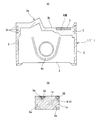
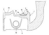
- FIG. 1A is a longitudinal sectional view of a piston of an internal combustion engine according to the present invention, and B is an enlarged view of a portion A shown in FIG. 1A.
- A is a longitudinal sectional view of a porous member provided for the present embodiment, and B is an enlarged view of a B portion shown in FIG. 2A.
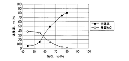
- It is a characteristic view which shows a void
- the piston 1 is integrally cast with an AC8A Al—Si aluminum alloy as a base material, and is formed in a substantially cylindrical shape as shown in FIG. 1A, and a crown defining a combustion chamber by a crown surface 2a.
- Part 2 a pair of arc-shaped thrust side skirt part 3 and anti-thrust side skirt part 3 integrally provided on the outer peripheral edge of the lower end of crown part 2, and both circumferential ends of each skirt part 3
- a pair of connected apron parts 4 and 4 are provided.
- the apron portion 4 is integrally provided with pin boss portions 4a and 4a formed with pin holes 4b and 4b for supporting both ends of a piston pin (not shown).
- the crown portion 2 has a disk shape formed with a relatively large thickness, the crown surface 2a constituting the combustion chamber is formed in a substantially concave-convex shape, and a flat concave portion 2b having a large surface area is formed in part.
- a low thermal conductivity portion 5 having a lower thermal conductivity than the piston base material 1 ′ is embedded in a predetermined position on the upper surface of the recess 2b.
- three piston ring grooves 2 c are formed on the outer periphery of the crown portion 2.
- the low thermal conductivity portion 5 is a position where fuel is directly injected from an injector, which is a fuel injection valve provided in a cylinder head (not shown), in the recessed portion 2b.
- an injector which is a fuel injection valve provided in a cylinder head (not shown), in the recessed portion 2b.
- the piston base material 1 is embedded in the porous member 6 made of a glass material having a lower thermal conductivity than the piston base material 1 ′. A part of the aluminum alloy material 1a is impregnated.
- the low thermal conductivity portion 5 is formed in a convex disk shape by a manufacturing method described later separately from the piston 1 and is made of the glass material, and the porous member 6 is prefilled.
- the aluminum alloy material 1a which is a part of the piston base material 1 'impregnated in the hole 9a after the water-soluble salt to be dissolved is dissolved, and a varnish 39 which will be described later impregnated in the hole 9a has been.
- Method for producing porous member Hereinafter, the outline of the manufacturing method of the porous member 6 will be described. First, a first powder 8 that is a glass powder that is insoluble in water, and a second powder 9 that is a water-soluble powder (sodium chloride powder).
- the mixed powder is put into a mold and press-molded at a predetermined pressure, and then sintered at a predetermined sintering temperature TB.
- the sintering temperature TB is lower than the sintering temperature TA of the second powder 9.
- the porous member 6 shown in FIG. 2 is formed.
- the porous member 6 has a thermal conductivity sufficiently lower than that of the piston base material 1 ′ that is a molten metal.
- the first powder 8 is a glass powder as described above, and is a hard and transparent substance mainly composed of silicate, borate, and phosphate, which is an amorphous solid that exhibits a glass transition phenomenon when heated. It is. Chemically, it is mainly a silicate compound (silicate mineral) that becomes glassy.
- silicate compound silicate mineral
- oxides constituting the glass SiO2, Al203, B203, BaO, Bi203, Li20, MgO, P205, PbO, SnO, TiO2, ZnO, R2O
- R is an abbreviation for alkali metals: Li, Na, K), RO (R is an alkaline earth metal; an abbreviation for Mg, Ca, Sr, Ba).
- the first powder 8 has a softening temperature (softening point) lower than the melting point of the second powder 9 and a melting point of 700 ° C. or higher.
- the glass transition point is a temperature at which the glass structure changes and has a viscosity of about 1013.3 poise.
- the softening point is a temperature at which the glass softens and deforms due to its own weight, and has a viscosity of about 107.6 poise.
- the second powder 9 is made of sodium chloride, potassium chloride, magnesium chloride, calcium chloride, calcium carbonate, sodium carbonate, sodium sulfate, magnesium sulfate, potassium sulfate, sodium nitrate, calcium nitrate, magnesium nitrate, potassium nitrate, Although water-soluble salts such as sodium borate, a mixed salt of one or two or more of them may be used.
- Sodium chloride and salts having a melting point exceeding 700 ° C. and water-soluble, such as potassium chloride, magnesium chloride, calcium chloride, calcium carbonate, sodium carbonate, sodium sulfate, magnesium sulfate, potassium sulfate, and sodium tetraborate are desirable.
- the sodium chloride is used.
- the second powder 9, which is sodium chloride, is stirred and mixed with the first powder 8 of borosilicate glass (powder glass ASF1898 manufactured by Asahi Glass Co., Ltd.).
- the mixing ratio of the first powder 8 and the second powder 9 was set to 40 to 20% by volume for the first powder 8 and 60 to 80% by volume for the second powder 9.
- a mixed powder having a weight ratio of 54:46 (weight ratio) was mixed (mixing step).
- the particle size of each powder was set such that the first powder 8 had an average particle size of 4.5 ⁇ m and the second powder 9 had a particle size of 75 to 180 ⁇ m of 70% or more.
- the mixed powder is put into a mold and press-molded, and heated and baked at a temperature of 650 ° C. to 750 ° C. for 20 to 40 minutes. In this embodiment, it is heated at a temperature of 700 ° C. for 30 minutes. Thus, a sintered compact was obtained (firing step).
- the sintered compact is immersed in a stirred 55 ° C. hot water (liquid) to dissolve the internal second powder 9 (sodium chloride) and extracted from the compact to have a large number of pores 9a. Member 6 was obtained (dissolution step).
- This melting step is performed in the range of 30 minutes to 3 hours with the second powder 9 in hot water of 50 ° C. to 95 ° C.
- the porous member 6 includes a disc-shaped base portion 6a and a small-diameter columnar projection portion 6b integrally provided on the upper surface of the base portion 6a.
- the first powder 8 glass
- the glass powder is surrounded around the sodium chloride particles.
- the porous member 6 is formed differently depending on the mixing ratio of the first powder 8 and the second powder 9.
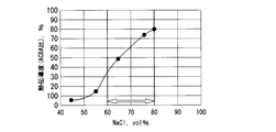
- the inventors of the present application conducted experiments in which the mixing ratio of the first powder 8 and the second powder 9 was variously changed, and the results shown in FIGS. 3 and 4 were obtained.
- the glass powder when the sodium chloride powder is 80% by volume or more and the glass powder is 20% by volume or less, the glass powder is not melt-bonded by heating. When it is melted with hot water, the molded body collapses.
- the glass powders are easily melted and joined by heating to cover the periphery of the sodium chloride powder. Accordingly, when the sodium chloride powder is melted with subsequent water or hot water, the sodium chloride powder cannot be contacted with water or hot water, and the porous member 6 cannot be molded.
- the sodium chloride powder is 60 to 80% by volume and the glass powder is 40 to 20% by volume, open holes 9a (holes connected from the surface to the inside) can be obtained. All the sodium chloride powder does not melt, and a part of it is covered with glass powder and is in a closed state. The amount of the sodium chloride powder in the closed state is determined by the mixing ratio of the sodium chloride powder (second powder 9) and the glass powder (first powder 8).
- the processed surface becomes a composite structure of glass as the porous member 6 and the cast alloy of the piston base material 1 ′, and the dissolved amount increases as the amount of sodium chloride powder increases.
- the surface area increases due to an increase in surface irregularities.
- the sodium chloride powder of the second powder 9 is set to 60 to 80% by volume, and the glass powder of the first powder 8 is set to 40 to 20% by volume.
- the porous member 6 mainly composed of the first powder 8 (glass) is placed in a die 10 for vacuum casting described later, and thereafter
- the piston 1 is cast by injecting molten aluminum alloy into the mold 10, and a part of the melt of the piston base material 1 ′ is placed in each hole 9 a of the porous member 6 during the casting of the piston 1.
- the low thermal conductivity portion 5 is integrally embedded in the recess 2b of the crown surface 2a by impregnation (injection step).
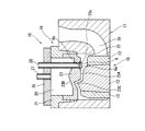
- FIG. Includes a center core 12 and a core 15 formed by combining a plurality of split cores such as a lip core 13 and a side core disposed around the center core 12 on the lower side.
- a pair of left and right wrist pins (not shown) that form a cooling path for circulating cooling water inside the mold 10 are horizontally provided opposite to each other, and the tip of the wrist pin is a hole formed in the side core. Is detachably engaged.
- the vacuum casting mold 10 is provided with a top core 19 that can be attached to and detached from the mold 11 on the upper side, and the top core 19 has a space portion as an example of a suction discharge portion 20.
- the outer top core 21 is provided, and the inner top core 23 is provided integrally with the outer top core 21.
- the outer top core 21 is provided with an adapter 25 for sealing the suction / discharge portion 20 at an upper end portion, and a pipe-shaped first communication pipe 27 is provided at substantially the center of the adapter 25.
- the first communication pipe 27 communicates with the suction / discharge section 20 and is connected to negative pressure generating means such as a vacuum pump (not shown). Therefore, by operating the negative pressure generating means, the inside of the suction / discharge section 20 can be depressurized to a negative pressure.
- the inner top core 23 forms a cavity 22 between the core 15 and the mold 11 and is constituted by a gas-permeable mold (porous mold) made of a porous material.
- the cavity surface 23A on the lower surface of the inner top core 23 is formed on a transfer surface for transferring the crown surface 2a of the piston 1, and is formed on a finished surface by electric discharge machining. Accordingly, the aluminum alloy is excellent in heat resistance and wear resistance against molten metal, and does not cause galling.
- the thickness of the narrow portion of the crown surface combustion chamber of the crown surface 2a and the portion 23B corresponding to the edge of the piston 1 as a product is thicker than 2 mm and 12 mm or less. It is.
- a metal pipe-like second communication pipe 28 penetrating the inner top core 23, the suction / discharge section 20 and the adapter 25 from the vertical direction is provided at a predetermined position of the inner top core 23.
- a holding groove 23 c for holding the porous member 6 is formed at the lower end portion of the second communication pipe 28. That is, the porous member 6 is held in advance at a predetermined position on the cavity surface 23 ⁇ / b> A of the inner top core 23, and the protruding portion 6 b is fitted and held in the lower end portion of the second communication pipe 28.
- the base portion 6a is held in contact with the peripheral surface of the holding groove 23c.
- the second communication pipe 28 is connected to a negative pressure generating means such as a vacuum pump (not shown) at the upper end, similar to the first communication pipe 27. Therefore, by operating the negative pressure generating means, the inside of the porous member 6 previously held in the holding groove 23c is depressurized to a negative pressure, and the molten aluminum alloy 1a described later is made into many holes 9a. Is impregnated.
- a negative pressure generating means such as a vacuum pump (not shown) at the upper end, similar to the first communication pipe 27. Therefore, by operating the negative pressure generating means, the inside of the porous member 6 previously held in the holding groove 23c is depressurized to a negative pressure, and the molten aluminum alloy 1a described later is made into many holes 9a. Is impregnated.
- the suction / discharge part 20 when the suction / discharge part 20 is set to a negative pressure, the gas in the cavity 22 is sucked into the suction / discharge part 20 via the inner top core 23 and discharged to the outside, and the aluminum alloy injected into the cavity 22 is discharged.
- the molten metal is attracted to and directly contacts the cavity surface 23A (transfer surface) of the inner top core 23, and the shape of the cavity surface 23A is transferred as it is.
- the suction / discharge section 20 is set to a negative pressure to suck and discharge the gas in the cavity 22, and when the molten metal in the cavity 22 is sucked and directly adhered to the cavity surface 23 ⁇ / b> A of the inner top core 23,
- the suction of the portion corresponding to the edge is effectively performed, and the shape of the cavity surface 23A of the inner top core 23 can be accurately transferred even if the product is a thin portion or an edge portion.
- the mold 11 is provided with a runner 29 for supplying molten metal to the cavity 22, and the runner 29 communicates with the lower side of the cavity 22.
- a molten aluminum alloy is injected into the cavity 22 from the runner 29 of the mold 11 (injection process) and the inside of the suction discharge unit 20 is also injected.
- Use negative pressure At this time, the molten metal is supplied to the cavity 22 on the lower side of the cavity 22, and the suction and discharge part 20 is depressurized to a negative pressure, so that the gas in the cavity 22 causes the inner top core 23 to flow. Permeated and discharged to the outside.
- the pressure inside the porous member 6 is reduced to a negative pressure by the vacuum pump via the second communication pipe 28, so that the molten metal supplied into the cavity 22 is supplied to the negative pressure of the suction / discharge unit 20.
- the suction is brought into direct contact with the cavity surface 23 ⁇ / b> A (transfer surface) of the inner top core 23 to be in close contact therewith.
- the decompression motor (not shown) is driven to discharge the air in the suction / discharge section 20 and suck the suction.
- the discharge part 20 is decompressed.
- the gas in the cavity 22 permeates through the pores of the inner top core 23 which is a breathable mold (porous mold). Is discharged.
- the suction and discharge part 20 is depressurized so that the molten metal is attracted and adhered to the cavity surface 23A.
- the unevenness of the cavity surface 23A is transferred to the crown surface of the piston, and the portion 23B of the recess 23C of the cavity surface 23A corresponding to the convex portion of the piston crown surface is Since it is formed thinner than the other parts, the molten metal is attracted and adhered more effectively to this part, and even the part where the shape of the piston crown surface 2a is difficult to be formed can be formed with high accuracy. .
- the porous member 6 also has a negative pressure, a part of the molten aluminum in the cavity 22 is sucked into the porous member 6 and a large number of holes 9a in which sodium chloride is dissolved. It penetrates and is impregnated.
- the low heat transfer coefficient portion 5 impregnated with the same aluminum alloy material 1a as the piston base material 1 ' is embedded and fixed integrally with the piston base material 1'.
- the air holes 9a are impregnated with the aluminum alloy material 1a, but the second powder 9 (sodium chloride) remains slightly.
- the piston base material 1 ′ in which the low thermal conductivity portion 5 is integrated is taken out from the cooled vacuum casting mold 10.
- a cylindrical portion 2d is integrally formed on the outer surface of the low thermal conductivity portion 5 on the upper surface of the concave portion 2b of the piston base material 1 ′.
- the height of the cylindrical portion 2d is the low thermal conductivity portion. 5 is almost the same as the height of 5.
- the varnish 39 is impregnated by the varnish impregnation device in the air holes 9a on the upper surface of the low thermal conductivity portion 5 (porous member 6) of the piston base material 1 '.
- the main sealant types include epoxy resins, phenol resins, vinyl resins, butyral resins, and organic amine derivatives.
- the sealing material (impregnating agent) is preferably a low-viscosity material that can be easily impregnated into the pores, and means such as brush coating, dip coating, and spray coating are conceivable.
- the impregnation property of the varnish 39 into each hole 9a is improved by the following vacuum assisted varnish impregnation apparatus.
- the varnish 39 must be able to withstand the combustion heat of the injected fuel after curing as a sealant.
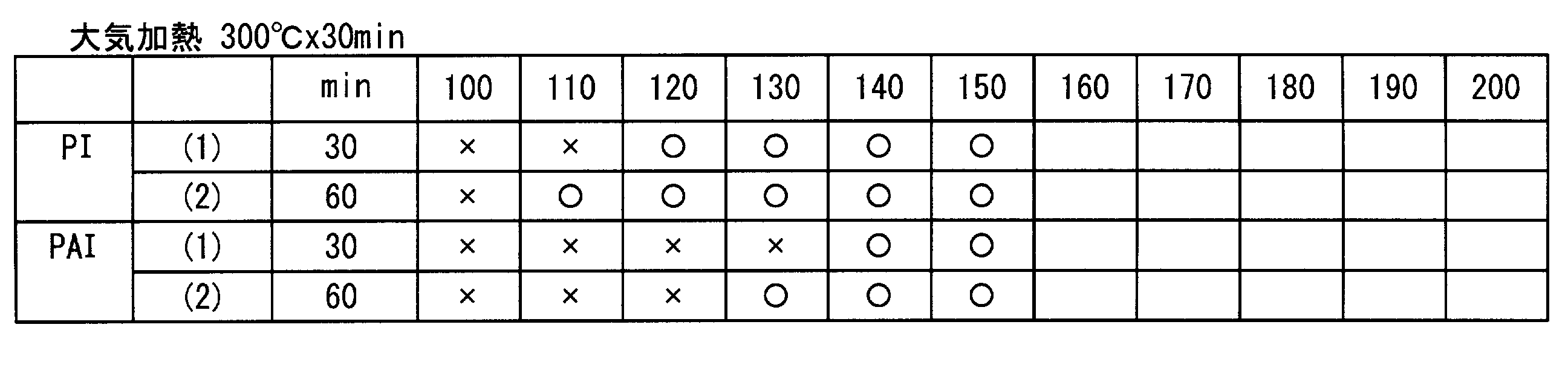
- the varnish 39 is a polyimide precursor or polyamideimide precursor having a glass transition temperature of 350 ° C. or higher. These are dissolved in a solvent mainly composed of DMA, DMF or GBL, which is selected from the following Tables 1 and 2 based on the results of experiments by the present inventors.
- the varnish 39 is not a precursor, and it is also possible to use an already imidized polyimide hot metal.
- PI and PAI (1) and (2) were heated for 30 to 60 minutes, and the varnish surface did not change from 100 ° C to 150 ° C. The surface was cured and the solvent was not volatilized, and it was swollen, and x was obtained.
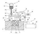
- the varnish impregnating apparatus is a vacuum vessel 30 which is a covered cylindrical cup-shaped member placed and held on the upper end surface of the cylindrical portion 2d formed in the concave portion 2b of the piston base material 1 ′. And a negative pressure introducing mechanism 31 for bringing the inside of the vacuum vessel 30 into a negative pressure state, and a varnish supplying mechanism 32 for supplying varnish to the outer surface of the low thermal conductivity portion 5.
- the vacuum vessel 30 is integrally formed of a relatively thick and highly rigid stainless steel metal material, and is disposed so as to cover the upper surface of the low thermal conductivity portion 5, and on the upper surface of the cylindrical portion 2d. It is mainly composed of a mounted cylindrical wall 30a and a disk-shaped upper wall portion 30b formed integrally with the upper end portion of the cylindrical wall 30a.
- the cylindrical wall 30a has an outer diameter that is slightly smaller than the outer diameter of the cylindrical portion 2d, and an inner diameter that is larger than the inner diameter of the cylindrical portion 2d, and is placed and held on the upper surface of the cylindrical portion 2d. Has been.
- the cylindrical portion 2d is integrally provided with an annular seal member 33 that seals between the lower surface and the upper surface of the cylindrical portion 2d.
- the upper wall portion 30b is formed with a first fixing hole 30c through which the vacuum pipe 35 of the negative pressure introducing mechanism 31 is inserted and fixed at a predetermined position on the outer peripheral side.
- a second fixing hole 30d through which the varnish supply pipe 41 of the varnish supply mechanism 32 is inserted and fixed is formed in the opposite position.
- the negative pressure introduction mechanism 31 includes a vacuum pump 34 which is a negative pressure generator for generating a negative pressure, one end 35a connected to the vacuum pump 34, and the other end 35b via the first fixing hole 30c.
- a vacuum pipe 35 that is a negative pressure introduction passage connected to the vacuum vessel 30, and a first on-off valve 36 that is provided in the middle of the vacuum pipe 35 and communicates with or cuts off the interior of the vacuum pipe 35.
- the first on-off valve 36 is mainly composed of a third on-off valve 38 provided on an atmospheric pressure introduction pipe 37 that branches from the downstream side and communicates with the atmosphere.
- the vacuum pump 34 is a general one using oil or the like, and sucks the inside of the vacuum vessel 30 with a predetermined suction pressure so as to be in a vacuum state.
- the first opening / closing valve 36 is opened / closed during the following varnish impregnation operation, opened during the operation of the vacuum pump 34, and closed when the operation is stopped. Further, after the closing operation, the third on-off valve 38 is opened.
- the varnish supply mechanism 32 includes a bottomed cylindrical storage tank 40 in which a varnish 39 as an impregnating agent is stored, one end 41a connected to the storage tank 40, and the other end 41b connected to the vacuum vessel 30.
- the varnish supply pipe 41 which is an impregnating agent introduction passage connected to the second fixing hole 30d, and a second on-off valve 42 provided in the middle of the varnish supply pipe 41 are mainly configured.
- the storage tank 40 is provided with a heater 43 on the entire outer periphery, and the heater 43 keeps the temperature of the varnish 39 constant in order to stabilize the viscosity of the internal varnish 39.
- the second open / close valve 42 opens and closes the varnish supply pipe 41 during the following varnish filling (supply) operation.
- the second open / close valve 42 opens when the inside of the vacuum vessel 30 is reduced to a predetermined pressure by the vacuum pump 34.
- the varnish 39 in the storage tank 40 is supplied to the upper surface 6 c side of the porous member 6 through the varnish supply pipe 41.
- the negative pressure introduction mechanism 31 and the varnish supply mechanism 32 are in a state of being connected to the vacuum container 30 in advance.
- the vacuum vessel 30 is placed on the upper surface of the cylindrical portion 2d on the crown portion 2 of the piston base material 1 ′ formed by the manufacturing process described above via the seal member 33. Fix it.
- the first on-off valve 36 is opened and the vacuum pump 34 is operated, and the first on-off valve 36 is closed when the pressure in the vacuum vessel 30 reaches 0.01 MPa or less.
- the second on-off valve 42 is opened, the varnish supply pipe 41 is communicated, and the varnish 39 is supplied into the vacuum container 30 so that the entire upper surface 6c of the porous member 6 is covered with the varnish 39. Cover it. Then, after the supply amount of the varnish 39 becomes an appropriate amount, the second on-off valve 42 is closed. As a result, the entire upper surface 6 c of the porous member 6 is covered with the varnish 39.
- the third on-off valve 38 is opened while the first on-off valve 36 is closed, whereby the atmospheric pressure is reduced from the atmospheric pressure introduction pipe 37 to the downstream side of the vacuum pipe 35. And supplied into the vacuum vessel 30.
- the varnish 39 is impregnated in a state of being strongly sucked by the atmospheric pressure into each of the holes 9a that have been in a vacuum state.
- the vacuum container 30, the negative pressure introduction mechanism 31, and the varnish supply mechanism 32 are removed from the piston base material 1 '.
- the low thermal conductivity portion 5 is provided in the portion where the fuel on the crown surface 2a of the piston 1 is directly injected, and the low heat conductivity portion 5 has a main structure that is higher than that of the aluminum alloy material. Since it is formed by the porous member 6 made of borosilicate glass having low thermal conductivity, high heat insulation can be obtained. Therefore, the atomization of the fuel is sufficiently promoted to improve the combustion performance and improve the fuel efficiency.
- the thermal conductivity of the low heat transfer coefficient portion 5 the smaller the porosity of the porous member 6 due to the holes 9a, the smaller the amount of impregnation of the aluminum alloy material 1a of the piston 1 into the holes 9a. Therefore, since the total volume ratio of the first powder 8 (glass powder) and the remaining sodium chloride powder is increased, the thermal conductivity is decreased.
- the surface area of the first powder 8 before removal and the remaining sodium chloride becomes only the glass component of the first powder 8 after the removal, and irregularities are formed. Therefore, the surface area increases.
- the thermal conductivity of the low thermal conductivity portion 5 decreases, the heat accumulation of the low thermal conductivity portion 5 increases, and the accumulated heat amount contributes to the atomization of the fuel.
- the larger the surface area the easier it is to transfer heat to the fuel, and the atomization of the fuel is promoted.
- the low thermal conductivity portion 5 is impregnated with the same aluminum alloy material 1a as the piston base material 1 'through many holes 9a, the aluminum alloy material 1a and the piston base material 1' The bondability is increased and the bond strength is improved.
- each of the holes of the varnish 39 is impregnated. Impregnation into 9a can be improved.
- the varnish 39 is directly supplied to the upper surface 6c of the porous member 6 and impregnated into each hole 9a by evacuation and atmospheric pressure, the impregnation effect of the varnish 39 is increased.
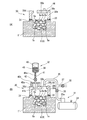
- FIG. 9 shows a second embodiment, in which a pipe connection connector 44 is attached in advance to a first fixing hole 30 c formed in the upper wall portion 30 b of the vacuum vessel 30.
- a cylindrical support member 45a and a lower end portion of the varnish supply pipe 41 are inserted and supported in the center at the upper portion of the hole edge of the second fixing hole 30d.
- a support piece 45b having a support hole is provided. The support member 45a and the support piece 45b are in liquid-tight contact with the vacuum vessel 30 by a predetermined seal member, and the edge of the support hole is also between the lower end of the varnish supply pipe 41. It is sealed.
- the vacuum pipe is connected to the connector 44 previously attached to the first fixing hole 30c. 35, the other end portion 35b of the varnish supply pipe 41 is connected to the upper portion of the second fixing hole 30d, and the lower end portion of the varnish supply pipe 41 is fixed to the support portion 45a.
- the tip end portion faces the inside of the vacuum container 30 while being inserted into the support hole of the support piece 45b.
- the varnish 39 is filled (impregnated) into each hole 9a of the porous member 6 by the same process as the varnish filling and impregnation process described above, and thus the same action as in the first embodiment. An effect is obtained.
- FIG. 10 shows a third embodiment.
- a varnish impregnation device is connected to each piston base material 1 ′, but in this embodiment, they are arranged in parallel. Further, four vacuum vessels 30...
- the present invention is not limited to the configuration of each of the above-described embodiments.
- a large number of piston base materials 1 ′ are continuously arranged on the production line, and on the cylindrical portion 2d of each piston base material 1 ′. It is also possible to continuously perform the sealing process by placing and fixing the vacuum containers 30 one after another.
- the sealing agent is made of a material containing polyimide or polyamideimide, which is an organic resin material, but can withstand the temperature environment of the crown surface 2a of the piston 1.
- a material containing polyimide or polyamideimide which is an organic resin material, but can withstand the temperature environment of the crown surface 2a of the piston 1.
- an inorganic material such as sodium silicate, alkyl silicate, organosiloxane, dichromate, or the like may be used.
Landscapes
- Engineering & Computer Science (AREA)
- Chemical & Material Sciences (AREA)
- Mechanical Engineering (AREA)
- General Engineering & Computer Science (AREA)
- Combustion & Propulsion (AREA)
- Materials Engineering (AREA)
- Organic Chemistry (AREA)
- Dispersion Chemistry (AREA)
- Geochemistry & Mineralogy (AREA)
- General Chemical & Material Sciences (AREA)
- Chemical Kinetics & Catalysis (AREA)
- Life Sciences & Earth Sciences (AREA)
- Ceramic Engineering (AREA)
- Manufacturing & Machinery (AREA)
- Pistons, Piston Rings, And Cylinders (AREA)
Abstract
Description
〔多孔質部材の製造方法〕
以下、前記多孔質部材6の製造方法の概略を説明すると、まず、水に溶けないガラスの粉末である第1粉体8と、水溶性の粉末(塩化ナトリウム粉末)としての第2粉体9を混合し、この混合粉を型に入れて所定圧で加圧成形した後、所定の焼結温度TBによって焼結させる。なお、この焼結温度TBは、第2粉体9の焼結温度TAよりも低い。
〔実施例〕
以下、多孔質部材6の具体的な製造方法について説明する。
〔ピストンの鋳造方法〕
したがって、前記金型10を用いてピストン1を鋳造するには、モールド型11の前記湯道29から前記キャビティ22内へアルミ合金の溶湯を注入する(注入工程)と共に、吸引排出部20内を負圧にする。この際、前記キャビティ22に対する溶湯の供給は、キャビティ22の下部側に行われ、前記吸引排出部20を減圧し負圧にすることにより、前記キャビティ22内の気体は、前記内トップコア23を透過して外部へ排出されるものである。

〔ワニス含浸装置〕
前記ワニス含浸装置は、図7に示すように、ピストン母材1’の凹部2bに形成された前記円筒部2dの上端面に載置保持された有蓋円筒状のカップ状部材である真空容器30と、該真空容器30の内部を負圧状態にする負圧導入機構31と、前記低熱伝導率部5の外面にワニスを供給するワニス供給機構32と、から構成されている。
〔第2実施形態〕
図9は第2実施形態を示し、真空容器30の上壁部30bに形成された第1固定用孔30cに、予めパイプ接続用のコネクタ44を取り付けられている。一方、前記第2固定用孔30dの孔縁の上部には、円筒状の支持部材45aと該支持部材45aの上端面に載置固定されて中央に前記ワニス供給パイプ41の下端部が挿通支持される支持孔を有する支持片45bが設けられている。また、前記支持部材45aと支持片45bは真空容器30に対して所定のシール部材によって液密的に当接していると共に、前記支持孔の孔縁もワニス供給パイプ41の下端部との間がシールされている。
〔第3実施形態〕
図10は第3実施形態を示し、前記第1、第2実施形態では、個々のピストン母材1’にワニス含浸装置を接続するようになっているが、この実施形態では、並行に並べられた4個のピストン母材1’の各円筒部2dの上面に、予め一体に結合された4つの真空容器30…を同時に載置固定し、該各真空容器30…の第1固定用孔30c…に、一つの真空導入機構31の4つに分岐形成された真空パイプ35の他端部35b…を接続する共に、一つのワニス供給機構32の4つに分岐形成されたワニス導入パイプ41の下端部41b…を接続したものである。
Claims (18)
- 冠面の所定位置に、ピストン母材よりも熱伝導率の低い低熱伝導率部が設けられている内燃機関用ピストンであって、
前記低熱伝導率部は、前記ピストン母材よりも熱伝導率の低い多孔質部材と、該多孔質部材の空孔内に含浸された含浸剤と、を有し、
該含浸剤は、機関駆動中の前記ピストンの使用環境下において前記空孔内に保持されていることを特徴とする内燃機関用ピストン。 - 請求項1に記載の内燃機関用ピストンにおいて、
前記含浸剤は、樹脂系材料によって形成されていることを特徴とする内燃機関用ピストン。 - 請求項2に記載の内燃機関用ピストンにおいて、
前記樹脂系材料は、ガラス転移温度が350℃以上であることを特徴とする内燃機関用ピストン。 - 請求項3に記載の内燃機関用ピストンにおいて、
前記樹脂系材料は、ポリイミドまたはポリアミドイミドを含む材料であることを特徴とする内燃機関用ピストン。 - 請求項1に記載の内燃機関用ピストンにおいて、
前記多孔質部材は、ベースの材料がガラス材によって形成され、内部に前記ピストン母材の一部が含浸されていると共に、前記ガラス材とピストン母材との間に、水溶性でかつ前記ガラス材よりも融点が高い材料を溶解して形成された前記空孔内に前記含浸剤が含浸されていることを特徴とする内燃機関用ピストン。 - 請求項5に記載の内燃機関用ピストンにおいて、
前記多孔質部材は、ホウ珪酸ガラスであることを特徴とする内燃機関用ピストン。 - 請求項5に記載の内燃機関用ピストンにおいて、
前記ピストン母材は、アルミニウム合金材であることを特徴とする内燃機関用ピストン。 - 請求項5に記載の内燃機関用ピストンにおいて、
前記ガラス材とピストン母材との間に、水溶性でかつ前記ガラス材よりも融点が高い材料は、塩化ナトリウムであることを特徴とする内燃機関用ピストン。 - 請求項1に記載の内燃機関用ピストンにおいて、
前記含浸剤は、無機質系材料であることを特徴とする内燃機関用ピストン。 - 冠面の所定位置に、ピストン母材よりも熱伝導率の低い低熱伝導率部が設けられている内燃機関用ピストンの製造方法であって、
前記ピストン母材の冠面に前記低熱伝導率部を一体に成形した後に、前記ピストン母材よりも熱伝導率の低い多孔質部材の表面を含む所定領域を減圧させる第1工程と、
前記第1工程の減圧中に、前記多孔質部材の複数の空孔に含浸剤を含浸させる第2工程と、
前記第2工程後に、前記所定領域を大気開放しこの大気圧によって前記複数の空孔内に含浸された含浸剤を充填させる第3工程と、
を備えたことを特徴とする内燃機関用ピストンの製造方法。 - 請求項10に記載の内燃機関用ピストンの製造方法において、
前記含浸剤は、ポリイミドまたはポリアミドイミドを含むワニスであることを特徴とする内燃機関用ピストンの製造方法。 - 請求項11に記載の内燃機関用ピストンの製造方法において、
前記第3工程後に、前記所定領域を加熱して溶媒を蒸発させて固形成分にする第4工程と、を有することを特徴とする内燃機関用ピストンの製造方法。 - 請求項12に記載の内燃機関用ピストンの製造方法において、
前記第4工程における加熱処理温度は、100~150℃の温度であることを特徴とする内燃機関用ピストンの製造方法。 - 請求項13に記載の内燃機関用ピストンの製造方法において、
前記加熱処理の時間は30~60分であることを特徴とする内燃機関用ピストンの製造方法。 - 請求項14に記載の内燃機関用ピストンの製造方法において、
前記加熱処理は、130℃の温度で30分間行うことを特徴とする内燃機関用ピストンの製造方法。 - 請求項10に記載の内燃機関用ピストンの製造方法において、
前記第1工程の前工程として、
前記ピストン母材よりも熱伝導率が低く、かつ熱によって軟化する第1粉体と、水溶性で、かつ前記第1粉体よりも融点温度が高い第2粉体とを攪拌混合することによって混合粉を生成する混合工程と、
前記混合粉体を加圧成形した後に焼成する焼成工程と、
該焼成工程後に、前記第2粉体を液体で溶解させて前記多孔質部材を形成する溶解工程と、
前記多孔質部材を金型内に設置した後に、前記多孔質部材を吸引または溶湯を加圧しながら前記金型内に注入してピストンを成形する共に前記多孔質部材の複数の空孔内にピストン母材を含浸させる注入工程と、
冷却された後に前記金型から取り出されたピストンの冠面を切削加工する切削工程と、
を有することを特徴とする内燃機関用ピストンの製造方法。 - 請求項16に記載の内燃機関用ピストンの製造方法において、
前記第1粉体は、ホウ珪酸ガラスである一方、前記第2粉体は、塩化ナトリウムであることを特徴とする内燃機関用ピストンの製造方法。 - 冠面の所定部位に、ピストン母材よりも熱伝導率の低い低熱伝導率部が設けられている内燃機関用ピストンの製造装置であって、
前記冠面の低伝導率部を形成する多孔質部材の表面を含む領域を覆うカップ状部材と、
一端部が前記カップ状部材に接続された負圧導入通路と、該負圧導入通路に設けられて、前記負圧導入通路を開閉する第1開閉弁と、前記負圧導入通路の他端部に設けられた負圧発生機と、を備えた負圧導入機構と、
一端部が前記カップ状部材に接続された含浸剤導入通路と、該含浸剤導入通路に設けられて、前記含浸剤導入通路を開閉する第2開閉弁と、前記含浸剤導入通路の他端部に設けられて、内部に含浸剤が貯留された貯留タンクと、を備えた含浸剤供給機構と、
前記カップ状部材に接続された大気導入通路に設けられて、前記カップ状部材内に大気圧を導入するかあるいは導入を遮断する第3開閉弁と、
を有することを特徴とする内燃機関用ピストンの製造装置。
Priority Applications (3)
| Application Number | Priority Date | Filing Date | Title |
|---|---|---|---|
| CN201580070230.8A CN107110061A (zh) | 2014-12-25 | 2015-10-13 | 内燃机用活塞和该活塞的制造方法及制造装置 |
| US15/536,808 US20170350343A1 (en) | 2014-12-25 | 2015-10-13 | Piston for internal combustion engine, and process and device for producing said piston |
| JP2016565978A JP6387114B2 (ja) | 2014-12-25 | 2015-10-13 | 内燃機関用ピストンと、このピストンの製造方法及び製造装置 |
Applications Claiming Priority (2)
| Application Number | Priority Date | Filing Date | Title |
|---|---|---|---|
| JP2014-261720 | 2014-12-25 | ||
| JP2014261720 | 2014-12-25 |
Publications (1)
| Publication Number | Publication Date |
|---|---|
| WO2016103856A1 true WO2016103856A1 (ja) | 2016-06-30 |
Family
ID=56149893
Family Applications (1)
| Application Number | Title | Priority Date | Filing Date |
|---|---|---|---|
| PCT/JP2015/078864 Ceased WO2016103856A1 (ja) | 2014-12-25 | 2015-10-13 | 内燃機関用ピストンと、このピストンの製造方法及び製造装置 |
Country Status (4)
| Country | Link |
|---|---|
| US (1) | US20170350343A1 (ja) |
| JP (1) | JP6387114B2 (ja) |
| CN (1) | CN107110061A (ja) |
| WO (1) | WO2016103856A1 (ja) |
Cited By (1)
| Publication number | Priority date | Publication date | Assignee | Title |
|---|---|---|---|---|
| CN115921789A (zh) * | 2022-12-09 | 2023-04-07 | 湖南江滨机器(集团)有限责任公司 | 活塞浇道系统、活塞浇铸模及其内浇口冷却方法 |
Families Citing this family (1)
| Publication number | Priority date | Publication date | Assignee | Title |
|---|---|---|---|---|
| GB2617132A (en) * | 2022-03-30 | 2023-10-04 | Airbus Operations Ltd | A brake component |
Citations (4)
| Publication number | Priority date | Publication date | Assignee | Title |
|---|---|---|---|---|
| JPS60182341A (ja) * | 1984-02-29 | 1985-09-17 | Isuzu Motors Ltd | 燃焼室壁面を多孔質断熱材で被覆した内燃機関 |
| JPH11193721A (ja) * | 1997-10-30 | 1999-07-21 | Toyota Central Res & Dev Lab Inc | 筒内噴射式火花点火機関 |
| JP2000203970A (ja) * | 1998-10-26 | 2000-07-25 | Puraseramu:Kk | 多孔質表面の処理方法、多孔質表面処理剤、表面処理物および重合促進剤 |
| WO2014017586A1 (ja) * | 2012-07-27 | 2014-01-30 | 日立オートモティブシステムズ株式会社 | 内燃機関のピストン及びこのピストンの製造方法 |
Family Cites Families (6)
| Publication number | Priority date | Publication date | Assignee | Title |
|---|---|---|---|---|
| JPS5823256A (ja) * | 1981-08-05 | 1983-02-10 | Toyota Motor Corp | ピストンリング |
| JPH03133560A (ja) * | 1989-10-16 | 1991-06-06 | Toyota Motor Corp | ピンホールを有する摺動部品への樹脂コーティング方法 |
| JP3751498B2 (ja) * | 2000-03-22 | 2006-03-01 | 本田技研工業株式会社 | アルミ合金製内燃機関用ピストン |
| JP2012172619A (ja) * | 2011-02-23 | 2012-09-10 | Aisin Seiki Co Ltd | エンジンおよびピストン |
| JP6067712B2 (ja) * | 2012-08-10 | 2017-01-25 | アイシン精機株式会社 | エンジンおよびピストン |
| JP5913227B2 (ja) * | 2013-08-05 | 2016-04-27 | トヨタ自動車株式会社 | 内燃機関とその製造方法 |
-
2015
- 2015-10-13 JP JP2016565978A patent/JP6387114B2/ja not_active Expired - Fee Related
- 2015-10-13 CN CN201580070230.8A patent/CN107110061A/zh active Pending
- 2015-10-13 WO PCT/JP2015/078864 patent/WO2016103856A1/ja not_active Ceased
- 2015-10-13 US US15/536,808 patent/US20170350343A1/en not_active Abandoned
Patent Citations (4)
| Publication number | Priority date | Publication date | Assignee | Title |
|---|---|---|---|---|
| JPS60182341A (ja) * | 1984-02-29 | 1985-09-17 | Isuzu Motors Ltd | 燃焼室壁面を多孔質断熱材で被覆した内燃機関 |
| JPH11193721A (ja) * | 1997-10-30 | 1999-07-21 | Toyota Central Res & Dev Lab Inc | 筒内噴射式火花点火機関 |
| JP2000203970A (ja) * | 1998-10-26 | 2000-07-25 | Puraseramu:Kk | 多孔質表面の処理方法、多孔質表面処理剤、表面処理物および重合促進剤 |
| WO2014017586A1 (ja) * | 2012-07-27 | 2014-01-30 | 日立オートモティブシステムズ株式会社 | 内燃機関のピストン及びこのピストンの製造方法 |
Cited By (1)
| Publication number | Priority date | Publication date | Assignee | Title |
|---|---|---|---|---|
| CN115921789A (zh) * | 2022-12-09 | 2023-04-07 | 湖南江滨机器(集团)有限责任公司 | 活塞浇道系统、活塞浇铸模及其内浇口冷却方法 |
Also Published As
| Publication number | Publication date |
|---|---|
| CN107110061A (zh) | 2017-08-29 |
| JP6387114B2 (ja) | 2018-09-05 |
| JPWO2016103856A1 (ja) | 2017-06-08 |
| US20170350343A1 (en) | 2017-12-07 |
Similar Documents
| Publication | Publication Date | Title |
|---|---|---|
| US10006402B2 (en) | Piston for internal combustion engine and method for manufacturing piston | |
| JP5976941B2 (ja) | 内燃機関用ピストンの製造方法 | |
| JP6321934B2 (ja) | エンジン燃焼室に臨む部材表面の断熱層の製造方法 | |
| US20170241372A1 (en) | Method for manufacturing piston for internal combustion engine and frictional hole sealing device for piston for internal combustion engine | |
| CN104496507B (zh) | 一种面向燃气轮机热端部件的复杂结构陶瓷零件制造方法 | |
| JP6387114B2 (ja) | 内燃機関用ピストンと、このピストンの製造方法及び製造装置 | |
| CN106194483A (zh) | 一种隔热活塞 | |
| JP5928419B2 (ja) | 遮熱膜とその形成方法 | |
| US20160121390A1 (en) | Precision-casting core, precision-casting core manufacturing method, and precision-casting mold | |
| CN107000038A (zh) | 蜡模的表面处理剂以及制造牙科假体的方法 | |
| CN114907133A (zh) | 一种硅基陶瓷型芯材料、制备方法以及硅基陶瓷型芯 | |
| KR101761046B1 (ko) | 정밀 주조용 중자 및 그 제조 방법, 정밀 주조용 주형 | |
| JP2016159324A (ja) | 鋳型の製造方法 | |
| CN105860886B (zh) | 用于粉末注射成型的复合粘结剂、制备及应用方法 | |
| JP5906996B2 (ja) | エンジン燃焼室部材の断熱構造体及びその製造方法 | |
| US8297338B2 (en) | Sand core for casting and process for producing the same | |
| JP2014138951A (ja) | 遮熱膜の形成方法 | |
| US10166598B2 (en) | Precision-casting core, precision-casting core manufacturing method, and precision-casting mold | |
| CN104500387B (zh) | 一种用于复合铜合金的柱塞泵缸体结构及其复合方法 | |
| JP2009233692A (ja) | 射出ポンプ用主筒およびこれを用いたホットチャンバダイカストマシン | |
| JP2008019484A (ja) | 金属複合材および金属複合材の製造方法 | |
| KR20220026867A (ko) | 소결재를 사용한 고압 주조방법 및 고압 주조품 | |
| JP2014231076A (ja) | 精密鋳造用中子及びその製造方法、精密鋳造用鋳型 | |
| JPH10244346A (ja) | 高圧鋳造用中子の成形方法 |
Legal Events
| Date | Code | Title | Description |
|---|---|---|---|
| 121 | Ep: the epo has been informed by wipo that ep was designated in this application |
Ref document number: 15872425 Country of ref document: EP Kind code of ref document: A1 |
|
| ENP | Entry into the national phase |
Ref document number: 2016565978 Country of ref document: JP Kind code of ref document: A |
|
| WWE | Wipo information: entry into national phase |
Ref document number: 15536808 Country of ref document: US |
|
| NENP | Non-entry into the national phase |
Ref country code: DE |
|
| 122 | Ep: pct application non-entry in european phase |
Ref document number: 15872425 Country of ref document: EP Kind code of ref document: A1 |