WO2016103813A1 - 動揺低減装置及びこれを備えた浮体 - Google Patents
動揺低減装置及びこれを備えた浮体 Download PDFInfo
- Publication number
- WO2016103813A1 WO2016103813A1 PCT/JP2015/076288 JP2015076288W WO2016103813A1 WO 2016103813 A1 WO2016103813 A1 WO 2016103813A1 JP 2015076288 W JP2015076288 W JP 2015076288W WO 2016103813 A1 WO2016103813 A1 WO 2016103813A1
- Authority
- WO
- WIPO (PCT)
- Prior art keywords
- floating body
- arm
- plate portion
- support arm
- use position
- Prior art date
- Legal status (The legal status is an assumption and is not a legal conclusion. Google has not performed a legal analysis and makes no representation as to the accuracy of the status listed.)
- Ceased
Links
Images

Classifications
-
- G—PHYSICS
- G06—COMPUTING OR CALCULATING; COUNTING
- G06F—ELECTRIC DIGITAL DATA PROCESSING
- G06F3/00—Input arrangements for transferring data to be processed into a form capable of being handled by the computer; Output arrangements for transferring data from processing unit to output unit, e.g. interface arrangements
- G06F3/12—Digital output to print unit, e.g. line printer, chain printer
- G06F3/1201—Dedicated interfaces to print systems
- G06F3/1223—Dedicated interfaces to print systems specifically adapted to use a particular technique
- G06F3/1237—Print job management
- G06F3/1253—Configuration of print job parameters, e.g. using UI at the client
- G06F3/1258—Configuration of print job parameters, e.g. using UI at the client by updating job settings at the printer
-
- G—PHYSICS
- G06—COMPUTING OR CALCULATING; COUNTING
- G06F—ELECTRIC DIGITAL DATA PROCESSING
- G06F3/00—Input arrangements for transferring data to be processed into a form capable of being handled by the computer; Output arrangements for transferring data from processing unit to output unit, e.g. interface arrangements
- G06F3/12—Digital output to print unit, e.g. line printer, chain printer
- G06F3/1201—Dedicated interfaces to print systems
- G06F3/1202—Dedicated interfaces to print systems specifically adapted to achieve a particular effect
- G06F3/1203—Improving or facilitating administration, e.g. print management
- G06F3/1205—Improving or facilitating administration, e.g. print management resulting in increased flexibility in print job configuration, e.g. job settings, print requirements, job tickets
-
- G—PHYSICS
- G06—COMPUTING OR CALCULATING; COUNTING
- G06F—ELECTRIC DIGITAL DATA PROCESSING
- G06F3/00—Input arrangements for transferring data to be processed into a form capable of being handled by the computer; Output arrangements for transferring data from processing unit to output unit, e.g. interface arrangements
- G06F3/12—Digital output to print unit, e.g. line printer, chain printer
- G06F3/1201—Dedicated interfaces to print systems
- G06F3/1223—Dedicated interfaces to print systems specifically adapted to use a particular technique
- G06F3/1237—Print job management
- G06F3/1253—Configuration of print job parameters, e.g. using UI at the client
- G06F3/1257—Configuration of print job parameters, e.g. using UI at the client by using pre-stored settings, e.g. job templates, presets, print styles
-
- G—PHYSICS
- G06—COMPUTING OR CALCULATING; COUNTING
- G06K—GRAPHICAL DATA READING; PRESENTATION OF DATA; RECORD CARRIERS; HANDLING RECORD CARRIERS
- G06K15/00—Arrangements for producing a permanent visual presentation of the output data, e.g. computer output printers
- G06K15/002—Interacting with the operator
Definitions
- the present invention relates to a sway reduction device mounted on a floating body and a floating body including the same.
- floating structures (hereinafter also simply referred to as floating bodies) have been widely applied as water facilities such as oceans, lakes, and rivers.
- floating bodies include various work boats, drill ships, oil production platforms, floating piers, floating warehouses, and floating parking lots. Since it is not necessary to install a support column on the bottom of the water, the structure of the floating body can be simplified. On the other hand, since the wave enters and shakes the floating body, it is necessary to reduce the shaking of the floating body.
- Patent Document 1 describes a technique in which a plate is suspended within a predetermined distance from the seabed, and the vibration is reduced by a fluid force acting on the plate in anticipation of an increase in additional mass and viscous damping force.
- Patent Document 2 an inclined plate inclined to the upstream side of the wave traveling direction and extending from the vicinity of the waterline of the floating body to the vicinity of the lower surface depth is attached to the side of the wave incident side of the floating body. A technique to be illustrated is described.
- Patent Document 3 a vertical plate extending downward from the bottom surface of the floating body is arranged at the lower end of the side portion on the wave incident side with a space that allows water to flow through the floating body, the vertical plate can be tilted, A technique for reducing the shaking by tilting is described.
- Patent Document 4 describes a technique for reducing fluctuation by reducing the influence of wave force by setting the ratio of the width of the box-shaped floating body to the flooded water to the ratio of the length and width of the box-shaped floating body. Has been.
- the present invention is intended to solve such a problem, and without causing an increase in the size of the apparatus, it is possible to reliably obtain a floating body sway reduction effect with a simple structure, and to suppress an increase in resistance when towing the floating body.
- the fluctuation reducing device of the present invention is arranged at the corner portion between the side surface and the bottom surface of the floating body with a base end spaced from the corner portion, and the floating body is located near the tip.
- the support portion functions as a resistance surface that blocks the water flow that is about to advance toward the surface, and the support portion includes a support arm to which the plate portion is fixed, and the support portion is moved to move the plate portion to a use position below the water surface.
- a movable mechanism that moves between the raised position on the water surface It is characterized by having.
- the support part has a holding mechanism that holds the plate part in the use position and the lifting position.
- the plate portion is fixed to a lower end portion of the support arm arranged in a vertical direction, and the movable mechanism is supported by a rack provided in the support arm along the axial direction and an upper portion of the floating body.
- the driving pinion meshes with the rack, a guide member that guides the support arm to be slidable in a vertical direction, and a motor that rotationally drives the driving pinion.
- the support arm includes a first arm part and a second arm part that are detachably coupled, and an expansion / contraction mechanism that expands and contracts the first arm part and the second arm part, and the plate Is fixed to a lower end portion of the second arm portion, the rack is formed on the first arm portion, and when the plate portion is brought into the use position, the telescopic mechanism is operated to operate the second arm portion. Is preferably extended downward from the first arm portion, and the motor is operated to lower the first arm portion.
- the plate portion is fixed to the distal end portion of the support arm, the proximal end of the support arm is pivotally supported on the upper part of the floating body, and the movable mechanism has the distal end portion of the support arm in the vertical direction.
- the support arm includes a first arm part and a second arm part that are coupled to each other by a coupling part, and a lock that fixes the first arm part and the second arm part in an extended state when the first arm part and the second arm part are extended.
- the plate portion is fixed to a distal end portion which is a free end side of the second arm portion, and a base end portion which is a free end side of the first arm portion is equipped with the actuator, When the plate portion is set to the use position, the actuator is operated so that the end portion of the first arm portion on the coupling portion side is turned vertically downward, and the lock mechanism is operated to operate the first arm. It is preferable to fix the arm portion and the second arm portion in an extended state.
- the size of the gap between the base portion of the plate portion and the corner portion is determined by a region in which the water flow guided to the bottom surface of the plate portion and entering the bottom surface from the gap is in the vicinity of the corner portion of the bottom surface. In order to form a high-speed laminar flow, it is preferably set small.
- the plate portion has an inclined portion extending obliquely downward outside the side surface of the floating body from the vicinity of the corner portion at the use position.
- the plate portion has the inclined portion and a vertical portion bent from the inclined portion and extending vertically downward at the use position.
- the plate portion is installed over the entire length of the side surface of the floating body.
- the floating body of the present invention is characterized in that it has a corner portion between a side surface and a bottom surface and the corner portion is equipped with the above-described vibration reduction device.
- the sway reduction device is installed on each of the side surfaces on both sides of the floating body.
- the upward surface of the plate portion functions as a guide surface, and the water flow that enters the side surface from the outside of the side surface of the floating body is collected by the pushing waves of the waves. Since the guide is directed toward the gap with the part, the water flow gathers in the gap and increases the speed, and enters the gap just below the bottom surface. Since the water current flows along the bottom surface at high speed, a negative pressure acts on the lower portion of the bottom surface near the corner portion, and acts on the floating body so as to pull down the bottom surface near the corner portion. The push wave acts to raise the side surface with respect to the floating body, but the negative pressure acts on the float body so as to cancel this, so that the floating body is prevented from being shaken by the push wave.
- the downward surface of the plate portion functions as a resistance surface, preventing water flow that moves outward from the bottom surface due to the wave pulling of the waves, so that the water flow presses the resistance surface and the bottom surface near the corner portion It acts on the floating body to push it upward.
- the pulling wave acts to lower the side surface with respect to the floating body, but the force that presses the resistance surface due to the water flow acts on the floating body so as to cancel this, so that the floating body is prevented from being shaken by the pulling wave.
- the movable part can easily set the plate part to the use position below the water surface, and can be moved from the use position to the pulling position on the water surface. It can be pulled up on the water surface so that the plate portion does not act as a resistor, and the floating body can be towed smoothly and without causing deterioration in fuel consumption.
- the board part of a use position is protruded toward the outer side of a side surface, it becomes a hindrance to berthing, but a floating body can be pierced without trouble by pulling up a board part on the water surface.
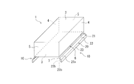
- FIG. 1 is a perspective view showing a sway reduction device and a floating body including the same according to each embodiment of the present invention.
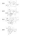
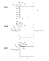
- 2A to 2D are cross-sectional views of the floating body for explaining the operation principle of the fluctuation reducing device according to each embodiment of the present invention, and FIG. 2A is a diagram for explaining the fluctuation of the floating body not equipped with the present apparatus.
- FIG. 2D is a diagram for explaining the operating principle of this apparatus.
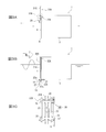
- 3A to 3C are views showing the configuration of the sway reduction device according to the first embodiment of the present invention, and FIG. 3A is a cross-sectional view of the floating body showing a state in which the fin (plate portion) is in the lifting position.
- FIG. 3B is a cross-sectional view of the floating body showing a state where the fin is in the use position
- FIG. 3C is an enlarged view showing the moving mechanism.
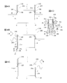
- 4A to 4C are views showing the configuration of the fluctuation reducing device according to the second embodiment of the present invention
- FIG. 4A is a cross-sectional view of a floating body showing a state where fins (plate portions) are in the lifting position
- 4B and 4C are cross-sectional views of the floating body showing a state where the fin is in the use position
- FIG. 4D is an enlarged view showing the moving mechanism.
- 5A to 5C are diagrams showing the configuration of the fluctuation reducing device according to the third embodiment of the present invention
- FIG. 5A is a cross-sectional view of a floating body showing a state where fins (plate portions) are in a use position.
- 5B is a cross-sectional view of the floating body showing a state in which the fin is moving to the lifting position
- FIG. 5C is a cross-sectional view of the floating body showing a state where the fin is in the lifting position. It is sectional drawing explaining the shape of the fin (plate part) concerning each embodiment. It is sectional drawing explaining the modification of the movable mechanism concerning 1st, 2 embodiment.
- the vertical upper direction is the upper or upper direction
- the vertical lower side is the lower or lower direction
- the direction toward the center line of the center in the width direction of the floating body is the inner side or the inner side.
- the direction away from the center line will be described as outward or outward.
- FIG. 1 is a perspective view showing a floating body (floating structure) equipped with the fluctuation reducing device according to each embodiment.
- a floating body 1 is a box-shaped (substantially rectangular parallelepiped) having an upper surface portion (upper surface) 2, a lower surface portion (lower surface) 3, both side surface portions (side surfaces) 4, 4, and both end surface portions (end surfaces) 5, 5.
- the shake reduction apparatus 10 is equipped with only one side part 4, or in addition to both or one side part 4 You may equip both or one end surface part 5.
- the sway reduction device 10 includes a fin (plate part) 20, and the fin 20 is supported by a support unit coupled to the floating body 1 although not shown in FIG. Has been.
- the fin 20 is arranged at the corner 6 between the side surface 4 and the bottom surface 3 of the floating body 1 with the base end 21 opened from the corner 6 with a gap 7 therebetween, and the tip end protrudes toward the lateral outer side of the floating body 1. Used in the state.
- the fin 20 is inclined from the vicinity of the corner 6 to the outside of the side surface 4 of the floating body 1 and obliquely downward at the use position, and is bent from the tip of the inclined portion 22 and extends vertically downward. And a vertical portion 23.
- An upward surface 22a of the fin 20 collects a water flow entering from the outside of the side surface 4 toward the side surface 4 by a wave pushing wave toward the gap 7. It functions as a guide surface for guiding.
- the size of the gap 7 is such that the water flow guided by the upward surface 22 a of the fin 20 and entering just below the bottom surface 3 from the gap 7 forms a high-speed laminar flow in the region near the corner 6 of the bottom surface 3. It is preferable to set it small.
- the downward surface of the fin 20 (that is, the downward surface facing the obliquely inner side of the inclined portion 22) 22b and the inward surface 23b of the vertical portion 23 flow outward from the bottom surface 3 due to wave pulling waves. It functions as a resistance surface that prevents
- FIG. 2A when a pressing wave is pushed toward the side surface 4 from the side [left side in FIG. 2A], a clockwise wave forcing moment M1 is applied to the floating body 1 as indicated by the white arrow in FIG. If the fluctuation reducing device 10 is not provided, the floating body 1 will roll.
- the guide surface 22 a of the fin 20 collects the water flow that enters the side surface 4 from the outside of the side surface 4 due to the pushing waves of the waves. Then, it guides toward the gap 7 between the base 21 and the corner 6 of the fin 20 (see FIG. 2D). Since the water stream gathers in the gap 7 as shown by a single-line arrow and increases the speed and enters the gap immediately below the bottom surface 3 from the gap 7, the water stream flows along the bottom surface 3 while forming a high-speed laminar flow.
- the resistance surface 22b, 23b of the fin 20 becomes a resistance to block this water flow against the water flow that advances outward from the bottom surface 3 due to the wave pulling wave.
- the resistance surfaces 22b and 23b are pressed, and a force F2 that pushes the bottom surface 3 upward acts on the floating body 1 under the bottom surface 3 near the corner 6 (see FIG. 2D).
- the counterclockwise wave forcing force moment M2 is applied to the floating body 1 by the pulling wave, since the force F2 acts so as to cancel the wave forcing force moment M2, the fluctuation of the floating body 1 due to the pulling wave is suppressed. .
- the sway reduction device 10 uses a guide surface 22a of the fin 20 to prevent the water flow WF1 entering from the outside of the side surface 4 toward the side surface 4 due to the pushing waves of the waves.
- the water flow WF1 is collected and guided from the gap 7 directly below the bottom surface 3, and the resistance surface 22b, 23b of the fin 20 is against the water flow WF2 that is going to move outward from the bottom surface 3 due to the wave drawing. This prevents the water flow WF2 from flowing out from the gap 7.
- Each of the following embodiments is a fluctuation reducing device having the fin 20 that reduces the fluctuation of the floating body 1 in this way, but the fin 20 is movable between a use position below the water surface and a pulling position on the water surface. It is characterized in that it is configured.
- the fluctuation reduction device 10A according to the first embodiment of the present invention will be described.
- the fluctuation reducing device 10 ⁇ / b> A is provided only on the side surface 4 on one side of the floating body 1, and includes a fin 20 and a support 30 ⁇ / b> A that is coupled to the floating body 1 and supports the fin 20.
- the floating body 1 is used by being moored by arranging the side surface 4 on one side equipped with the vibration reduction device 10 ⁇ / b> A in the direction of the open ocean where waves enter.
- the fin 20 has, in the use position, an inclined portion 22 that extends obliquely downward outside the side surface 4 of the floating body 1 from the vicinity of the corner portion 6, and bends from the tip of the inclined portion 22 and extends vertically downward. And an extended vertical portion 23.
- the upward surface 22a of the inclined portion 22 of the fin 20 functions as a guide surface that collects the water flow entering from the outside of the side surface 4 toward the side surface 4 by the wave pushing waves and guides it toward the gap 7 (see FIG. 1).
- the downward surface 22b of the inclined portion 22 of the fin 20 and the inward surface 23b of the vertical portion 23 function as a resistance surface that prevents a water flow that advances outward from the bottom surface 3 due to the wave pulling.
- the fins 20 extend in the longitudinal direction of the floating body 1 (the direction in which the corners 6 extend), and the length is set so as to cover the entire length in the longitudinal direction of the floating body 1 or substantially the entire length.
- the fins 20 are supported by the support portion 30A at a plurality of locations in the longitudinal direction, for example, at three locations near both ends and an intermediate portion, or at a plurality of locations near both ends and an intermediate portion.
- the fin 20 is one piece having a length over the entire length of the floating body 1 or substantially the entire length, but the fin 20 is divided into a plurality of portions in the longitudinal direction, and each of them is supported by the support portion 30A in the same manner as described above. You may support.
- the support portion 30A includes a support arm 31A to which the fin 20 is fixed, and a movable mechanism 32A that moves the support arm 31A to move the fin 20 between a use position below the water surface and a pull-up position on the water surface. is doing.
- the support arm 31A has one length substantially along the height of the floating body 1, is arranged in the vertical direction, has the fin 20 fixed to the lower end portion, and is driven up and down by the movable mechanism 32A.
- the movable mechanism 32A is supported by a rack (linear tooth row) 33 provided along the axial direction on the support arm 31A and an upper portion of the floating body 1 (here, an upper portion of the side surface 4).
- the drive pinion 34 meshes with the rack 33, a guide pinion (guide member) 35, and a motor 36 that rotationally drives the drive pinion 34.
- the drive pinion 34 and the guide pinion 35 are supported on the upper part of the side surface 4 via a bracket 37.
- the motor 36 an electric motor or a hydraulic motor can be used as appropriate.
- racks 33 are provided in parallel and back-to-back on the outside and inside of the support arm 31A, respectively, and a drive pinion 34 and one guide pinion 35 are lined up and down, and one (here, the inside) rack 33 is arranged.
- the two guide pinions 35 and 35 are arranged vertically so as to face the inner drive pinion 34 and the guide pinion 35, and engage with the other (here, the outer) rack 33. Is arranged.
- the rack 33 can be moved up and down and the support arm 31A can be moved up and down.
- the guide pinion 35 guides the support arm 31 ⁇ / b> A so as to be slidable in the vertical direction so that the support arm 31 ⁇ / b> A moves up and down while maintaining the vertical posture while being rotated following the movement of the rack 33.
- the motor 36 has a built-in brake that restricts rotation, and this brake functions as a holding mechanism that holds the positions of the support arm 31A and the fin 20 in the vertical movement direction.
- the movable mechanism 32A is operated to support the arm 31A. Is moved downward in the vertical direction, the fin 20 is set at a predetermined use position below the water surface, and the brake of the motor 36 is operated to fix the support arm 31A. Thereby, it can set to a use position easily and also can obtain the rocking
- the fin 20 in the use position protrudes toward the outside of the side surface 4, it interferes with the berthing, but when the berthing is made, the fin 20 can be lifted onto the water surface, so that the floating body 1 can be berthed without any trouble.
- the lifting position of the fin 20 is higher than the assumed height of the quay.
- the fluctuation reducing device 10A is equipped only on the side surface 4 on one side of the floating body 1, the installation cost of the fluctuation reducing device 10A can be suppressed.
- the side surface 4 on both sides of the floating body 1 may be equipped with the sway reduction device 10A, respectively, so that any side surface 4 of the floating body 1 can be used toward the offshore side.
- the support arm 31A may be guided so as to be slidable in the vertical direction instead of a roller that contacts a portion of the support arm 31A where the rack 33 is not formed.
- the holding mechanism for holding the fin 20 at the use position and the pull-up position may use an individual mechanical stopper or the like.
- the sway reduction device 10B differs from the first embodiment in a part of the configuration of the support portion 30B, and the other configurations are configured substantially the same as in the first embodiment. Therefore, the same components as those in the first embodiment will be described with reference to the same reference numerals as those in the first embodiment, and the description thereof will be omitted. The differences from the first embodiment will be mainly described.
- the fluctuation reducing device 10B is mounted on each of the side surfaces 4 on both sides of the floating body 1, and is coupled to the fin 20 and the floating body 1 to form the fins.
- a support portion 30 ⁇ / b> B that supports 20.
- the fin 20 is inclined from the vicinity of the corner portion 6 to the outside of the side surface 4 of the floating body 1 and obliquely downward at the use position, and is bent from the tip of the inclined portion 22 and extends vertically downward.
- a vertical portion 23 is described above.
- the support portion 30B includes a support arm 31B to which the fin 20 is fixed, and a movable mechanism 32B that moves the support arm 31B to move the fin 20 between a use position below the water surface and a pull-up position on the water surface. is doing.
- the support arm 31B and the movable mechanism 32B are different from those of the first embodiment.
- the support arm 31B of the present embodiment includes a first arm part 31a and a second arm part 31b that are connected to be extendable and a telescopic mechanism 38 that extends and contracts the first arm part 31a and the second arm part 31b. is doing.
- the length is approximately along the height of the floating body 1 like the support arm 31A of the first embodiment.
- first arm portion 31a is formed in a hollow shape, and the second arm portion 31b can be accommodated in the hollow inside of the first arm portion 31a.
- the lower end inner periphery of the hollow portion of the first arm portion 31a is reduced in diameter
- the upper end outer periphery of the second arm portion 31b is increased in diameter
- the second arm portion 31b is on the extension side with respect to the first arm portion 31a.
- the reduced diameter portion and the enlarged diameter portion engage and fit to function as a holding mechanism that fixes the second arm portion 31b in the extended state.
- the movable mechanism 32B is provided along the axial direction on the rack (linear tooth row) 33a provided on the first arm portion 31a along the axial direction and on the second arm portion 31b.
- the drive pinion 34a and the guide pinion (guide member) 35 which are supported by the rack (straight tooth row) 33b, the upper part of the floating body 1 (upper part of the side surface 4) and mesh with the rack 33a, and the drive pinion 34a are driven to rotate Motor 36a, a drive pinion 34b and a guide pinion 35 that mesh with the rack 33b, and a motor 36b that rotationally drives the drive pinion 34b.
- the guide pinion 35 may further provide the guide pinion 35 arrange
- the rotation of the motor 36a is fixed, the movement of the first arm portion 31a is restricted, and the motor 36b is operated to move the second arm portion 31b.
- the expansion / contraction mechanism 38 is connected to each rack and pinion mechanism. And these motors 36a and 36b.
- the drive pinions 34a and 34b and the guide pinion 35 are supported on the upper portion of the side surface 4 via a bracket (not shown).
- the drive pinion 34b that meshes with the rack 33b of the second arm portion 31b and the guide pinion 35 that opposes the drive pinion 34b are separated by a separation mechanism (not shown) with respect to the second arm portion 31b, as indicated by a horizontal arrow in FIG. 4D.
- the drive pinion 34b and the guide pinion 35 are appropriately separated from the second arm portion 31b.
- the racks 33a and 33b can be moved up and down to raise and lower the support arm 31B.
- the motor 36a is fixed by a brake, and the motor 36b is operated to lower the second arm portion 31b.
- the second arm portion 31b moves to the extension side with respect to the first arm portion 31a, the reduced diameter portion and the enlarged diameter portion are fitted, and the second arm portion 31b is held in the extended state.
- the drive pinion 34b and the guide pinion 35 meshing with the rack 33b are separated from the second arm portion 31b, and the motor 36a is operated to lower the first arm portion 31a.
- the brake of the motor 36a is operated to fix the support arm 31B. To do.
- the motor 36a is operated with the drive pinion 34b and the guide pinion 35 meshing with the rack 33b being separated from the second arm portion 31b, so that the first arm portion is operated. 31a is raised.
- the second arm portion 31b fixed in the extended state together with the first arm portion 31a rises, and the rack 33b of the second arm portion 31b rises to the position of the drive pinion 34b and the guide pinion 35, the drive pinion 34b
- the motor 36a is fixed by a brake, and the motor 36b is operated to raise the second arm portion 31b.
- the torque of the motor 36b releases the fit between the reduced diameter portion and the enlarged diameter portion, and the second arm portion 31b becomes movable, and moves toward the contraction side with respect to the first arm portion 31a.
- the brake of the motor 36b is operated to fix the support arm 31B.
- the fluctuation reducing device 10B according to the second embodiment of the present invention is configured as described above, as in the first embodiment, as shown in FIG. 4B or FIG. Can be easily set at a predetermined use position below the surface of the water, and the motion reduction effect of the floating body 1 by the motion reduction device 10B having the fins 20 can be obtained.
- the movable mechanism 32B When towing the floating body 1 or bringing it into the berth, as shown in FIG. 4A, the movable mechanism 32B is operated to move the support arm 31B upward in the vertical direction, and the fin 20 is lifted on the water surface. And the brakes of the motors 36a and 36b are operated to fix the support arm 31B. Thereby, when the floating body 1 is towed, the floating body 1 can be smoothly towed without causing deterioration in fuel consumption, and when the floating body 1 is berthed, the floating body 1 can be pierced without any trouble.
- the sway reduction device 10B is installed on the side surfaces 4 and 4 on both sides of the floating body 1.
- the sway reduction device 10B is provided only on the side surface 4 on one side of the floating body 1. May be installed.
- the sway reduction device 10C according to the third embodiment of the present invention will be described.
- the fluctuation reducing device 10C is different from the first embodiment in the configuration of the support unit 130, and the other configurations are substantially the same as those in the first embodiment. Therefore, the same components as those in the first embodiment will be described with reference to the same reference numerals as those in the first embodiment, and the description thereof will be omitted. The differences from the first embodiment will be mainly described.
- the fluctuation reducing device 10C is provided only on the side surface 4 on one side of the floating body 1, and is coupled with the fin 20 and the floating body 1 to the fins. 20 and a support portion 130 that supports 20.
- the fin 20 is inclined from the vicinity of the corner portion 6 to the outside of the side surface 4 of the floating body 1 and obliquely downward at the use position, and is bent from the tip of the inclined portion 22 and extends vertically downward. And a vertical portion 23.
- the support arm 131 is pivotally supported at the upper part of the floating body 1 at the base end, and the fin 20 is fixed to the distal end portion of the support arm 131.
- a movable mechanism 132 for turning the support arm 131 is also provided.
- the movable mechanism 132 is between a state in which the tip of the support arm 131 is directed in the vertical direction and the fin 20 is in the use position, and a state in which the support arm 131 is pulled up to the top of the floating body 1 and the fin 20 is in the lift position.
- An actuator 136 for rotating the support arm 131 is provided.
- the support arm 131 includes a first arm portion 131a and a second arm portion 131b that are coupled to each other by a coupling portion 131c so that the first arm portion 131a and the second arm portion 131b are coupled to each other.
- a lock mechanism (not shown) is provided that fixes the extended state to the extended state.
- the fin 20 is fixed to a distal end portion that is a free end (an end not on the coupling portion 131c side) of the second arm portion 131b, and an actuator 136 is mounted on a proximal end portion 131d that is a free end side of the first arm portion 131a.
- the actuator 136 a hydraulic actuator, an electric actuator, or the like can be used as appropriate.
- the actuator 136 When setting the fin 20 to the use position, the actuator 136 is actuated so that the end of the first arm portion 131a on the coupling portion 131c side is turned vertically downward, and as shown in FIG. The first arm portion 131a and the second arm portion 131b are fixed in an extended state by operating. Further, the actuator 136 is brought into a locked state.
- the lock mechanism When setting the fin 20 from the use position to the lifting position, the lock mechanism is released so that the first arm portion 131a and the second arm portion 131b can be bent.
- the actuator 136 As shown in FIG. 5B, the actuator 136 is actuated so that the end of the first arm portion 131a on the coupling portion 131c side is turned up, and the end portion of the first arm portion 131a on the coupling portion 131c side is further turned.
- the actuator 136 is brought into a locked state by pulling it up to the upper surface portion 2 of the floating body 1 while turning the floating body 1 upward.
- the fluctuation reducing device 10C according to the third embodiment of the present invention is configured as described above, as in the first embodiment, as shown in FIG. Therefore, it is possible to obtain the motion reduction effect of the floating body 1 by the motion reduction device 10 ⁇ / b> C having the fins 20.
- the movable mechanism 132 When towing the floating body 1 or bringing it into the berth, as shown in FIG. 5C, the movable mechanism 132 is operated and the support arm 131 is pulled up by the actuator 136, and the fin 20 is set at the lifting position on the water surface. Then, the actuator 136 is fixed. Thereby, when the floating body 1 is towed, the floating body 1 can be smoothly towed without causing deterioration in fuel consumption, and when the floating body 1 is berthed, the floating body 1 can be pierced without any trouble.
- the vibration reduction device 10C is installed only on the side surface 4 on one side of the floating body 1. However, as in the second embodiment, the vibration reduction device 10C is installed in the floating body 1. You may install in the side surfaces 4 and 4 of both sides.
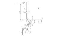
- FIG. 6 is a cross-sectional view of the fin 20 according to each embodiment in use. As described above, in the use position, the fin 20 is inclined from the vicinity of the corner portion 6 and extends obliquely downward outside the side surface 4 of the floating body 1 and is bent from the tip of the inclined portion 22 and extends vertically downward. And a vertical portion 23.
- the depth from the water surface of the bottom surface 3 of the floating body 1 is d
- the vertical position of the base end 21 of the fin 20 with respect to the floating body 1 is s
- the value with the downward direction being positive with respect to the bottom surface 3 of the floating body 1
- the fin 20 The horizontal direction position of the base end 21 of the floating body 1 with respect to the side surface 4 of the floating body 1 is x0 with the center direction of the floating body 1 being positive
- the length of the inclined portion 22 is b
- the inclined angle of the inclined portion 22 with respect to the vertical Is ⁇ and the length of the vertical portion 23 is h.
- the shape and arrangement as shown in Table 1 are preferable.
- the parameter x0 cannot be set to a value of 0 or more in order to avoid interference with the side surface 4. Therefore, in consideration of this, in the case of the first and second embodiments, in addition to the mechanism for vertically moving the fin 20, as shown by a two-dot chain line in FIG. 20 or a mechanism for shifting the support portions 30A, 30B toward the center of the floating body can be used to achieve the optimum state.
- the fin is used with at least the base end being spaced from the corner of the floating body and protruding toward the outside of the side surface of the floating body.
- the upward surface of the fin is It functions as a guide surface that collects the water flow that tries to enter the side from the outside of the side and guides it toward the gap, and the downward surface of the fin is a water flow that tries to advance from the bottom to the outside due to wave pulling waves. Any material may be used as long as it functions as a resistance surface that prevents the above.
Landscapes
- Engineering & Computer Science (AREA)
- Theoretical Computer Science (AREA)
- General Engineering & Computer Science (AREA)
- Physics & Mathematics (AREA)
- General Physics & Mathematics (AREA)
- Human Computer Interaction (AREA)
- Bridges Or Land Bridges (AREA)
- Other Liquid Machine Or Engine Such As Wave Power Use (AREA)
- Facsimiles In General (AREA)
Priority Applications (2)
| Application Number | Priority Date | Filing Date | Title |
|---|---|---|---|
| CN201580068794.8A CN107000824B (zh) | 2014-12-26 | 2015-09-16 | 摇晃减轻装置及具备该摇晃减轻装置的浮体 |
| SG11201705068UA SG11201705068UA (en) | 2014-12-26 | 2015-09-16 | Oscillation mitigation device and floating body provided with same |
Applications Claiming Priority (2)
| Application Number | Priority Date | Filing Date | Title |
|---|---|---|---|
| JP2014-265534 | 2014-12-26 | ||
| JP2014265534A JP6415314B2 (ja) | 2014-12-26 | 2014-12-26 | 動揺低減装置及びこれを備えた浮体 |
Publications (1)
| Publication Number | Publication Date |
|---|---|
| WO2016103813A1 true WO2016103813A1 (ja) | 2016-06-30 |
Family
ID=56149852
Family Applications (1)
| Application Number | Title | Priority Date | Filing Date |
|---|---|---|---|
| PCT/JP2015/076288 Ceased WO2016103813A1 (ja) | 2014-12-26 | 2015-09-16 | 動揺低減装置及びこれを備えた浮体 |
Country Status (5)
| Country | Link |
|---|---|
| US (1) | US9507554B2 (enExample) |
| JP (1) | JP6415314B2 (enExample) |
| CN (1) | CN107000824B (enExample) |
| SG (1) | SG11201705068UA (enExample) |
| WO (1) | WO2016103813A1 (enExample) |
Families Citing this family (2)
| Publication number | Priority date | Publication date | Assignee | Title |
|---|---|---|---|---|
| JP2017163355A (ja) * | 2016-03-09 | 2017-09-14 | 富士ゼロックス株式会社 | データ処理装置及びプログラム |
| JP7167523B2 (ja) * | 2018-07-27 | 2022-11-09 | セイコーエプソン株式会社 | 電子機器、表示制御プログラム |
Citations (8)
| Publication number | Priority date | Publication date | Assignee | Title |
|---|---|---|---|---|
| US2807228A (en) * | 1954-09-28 | 1957-09-24 | Bernard G Vandre | Adjustable rear flap for boats |
| JPS5710996U (enExample) * | 1980-06-24 | 1982-01-20 | ||
| JPS6092185A (ja) * | 1983-10-26 | 1985-05-23 | Noboru Morimoto | 船体横揺れ緩和装置 |
| JPH0719096U (ja) * | 1993-09-21 | 1995-04-04 | 日立造船株式会社 | 船舶の減揺装置 |
| JP2002037184A (ja) * | 2000-05-16 | 2002-02-06 | Mitsubishi Heavy Ind Ltd | 浮体の動揺低減装置およびこれを備えた浮体 |
| JP2004058691A (ja) * | 2002-07-24 | 2004-02-26 | Mitsubishi Heavy Ind Ltd | 浮体の動揺低減装置及びこれを備えた浮体 |
| JP2010228503A (ja) * | 2009-03-26 | 2010-10-14 | National Maritime Research Institute | 浮体式海洋構造物の減揺装置 |
| JP2013006578A (ja) * | 2011-05-20 | 2013-01-10 | Eiji Kawanishi | 船舶の減揺と浮上装置 |
Family Cites Families (22)
| Publication number | Priority date | Publication date | Assignee | Title |
|---|---|---|---|---|
| US6327051B1 (en) * | 1995-12-22 | 2001-12-04 | Canon Kabushiki Kaisha | Printing control apparatus and method |
| US20010056449A1 (en) * | 2000-04-27 | 2001-12-27 | Hirokazu Kawamoto | Information processing apparatus, print control apparatus, method of controlling an information processing apparatus, method of controlling a print control apparatus, and storage medium |
| JP2003223079A (ja) | 2002-01-30 | 2003-08-08 | Konica Corp | 画像形成装置 |
| JP4220759B2 (ja) * | 2002-11-11 | 2009-02-04 | 三菱重工業株式会社 | 浮体の動揺低減装置及びこれを備えた浮体 |
| JP4574344B2 (ja) * | 2004-01-20 | 2010-11-04 | キヤノン株式会社 | 情報処理装置及び方法 |
| KR20050122022A (ko) * | 2004-06-23 | 2005-12-28 | 삼성전자주식회사 | 프린터 드라이버를 구비한 인쇄제어장치 및 그를 이용한인쇄옵션 제어방법 |
| US20090089811A1 (en) * | 2007-09-27 | 2009-04-02 | Andrew Rodney Ferlitsch | Persistent per URL print settings |
| JP4894890B2 (ja) * | 2009-06-16 | 2012-03-14 | コニカミノルタビジネステクノロジーズ株式会社 | 情報処理装置、情報処理装置の制御方法、プログラム |
| KR20120008331A (ko) * | 2010-07-16 | 2012-01-30 | 현대중공업 주식회사 | 횡동요 억제장치 |
| JP5377447B2 (ja) * | 2010-08-27 | 2013-12-25 | 京セラドキュメントソリューションズ株式会社 | 表示入力装置及びこれを備えた画像形成装置 |
| JP5577206B2 (ja) * | 2010-09-22 | 2014-08-20 | 新日鉄住金エンジニアリング株式会社 | 動揺低減装置および浮体 |
| JP2012096601A (ja) * | 2010-10-29 | 2012-05-24 | Mitsubishi Heavy Ind Ltd | 浮体の動揺低減装置 |
| JP2012121446A (ja) * | 2010-12-08 | 2012-06-28 | Mitsubishi Heavy Ind Ltd | 浮体構造物の動揺低減装置 |
| JP5893294B2 (ja) * | 2011-08-26 | 2016-03-23 | キヤノン株式会社 | 画像処理装置及びその制御方法、並びにプログラム |
| JP5909940B2 (ja) * | 2011-09-07 | 2016-04-27 | 株式会社リコー | 画像形成装置、プログラム及び記録媒体 |
| JP5799698B2 (ja) * | 2011-09-14 | 2015-10-28 | 株式会社リコー | 情報処理装置及びプログラム |
| KR101454775B1 (ko) * | 2012-09-27 | 2014-10-27 | 삼성중공업 주식회사 | 동요 억제 장치 |
| JP5784052B2 (ja) * | 2013-01-29 | 2015-09-24 | 京セラドキュメントソリューションズ株式会社 | 電子機器及び画像形成装置 |
| JP6136321B2 (ja) * | 2013-02-06 | 2017-05-31 | 富士ゼロックス株式会社 | 情報処理装置、画像処理装置及びプログラム |
| JP6186761B2 (ja) * | 2013-03-07 | 2017-08-30 | ブラザー工業株式会社 | プログラム、および通信装置 |
| JP5892118B2 (ja) * | 2013-07-26 | 2016-03-23 | コニカミノルタ株式会社 | 印刷システム、プリントサーバー、情報処理装置、画像形成装置およびプログラム。 |
| CN203755282U (zh) * | 2014-01-02 | 2014-08-06 | 浙江海洋学院 | 一种可升降海洋平台 |
-
2014
- 2014-12-26 JP JP2014265534A patent/JP6415314B2/ja not_active Expired - Fee Related
-
2015
- 2015-09-16 WO PCT/JP2015/076288 patent/WO2016103813A1/ja not_active Ceased
- 2015-09-16 CN CN201580068794.8A patent/CN107000824B/zh not_active Expired - Fee Related
- 2015-09-16 SG SG11201705068UA patent/SG11201705068UA/en unknown
- 2015-12-08 US US14/962,640 patent/US9507554B2/en not_active Expired - Fee Related
Patent Citations (8)
| Publication number | Priority date | Publication date | Assignee | Title |
|---|---|---|---|---|
| US2807228A (en) * | 1954-09-28 | 1957-09-24 | Bernard G Vandre | Adjustable rear flap for boats |
| JPS5710996U (enExample) * | 1980-06-24 | 1982-01-20 | ||
| JPS6092185A (ja) * | 1983-10-26 | 1985-05-23 | Noboru Morimoto | 船体横揺れ緩和装置 |
| JPH0719096U (ja) * | 1993-09-21 | 1995-04-04 | 日立造船株式会社 | 船舶の減揺装置 |
| JP2002037184A (ja) * | 2000-05-16 | 2002-02-06 | Mitsubishi Heavy Ind Ltd | 浮体の動揺低減装置およびこれを備えた浮体 |
| JP2004058691A (ja) * | 2002-07-24 | 2004-02-26 | Mitsubishi Heavy Ind Ltd | 浮体の動揺低減装置及びこれを備えた浮体 |
| JP2010228503A (ja) * | 2009-03-26 | 2010-10-14 | National Maritime Research Institute | 浮体式海洋構造物の減揺装置 |
| JP2013006578A (ja) * | 2011-05-20 | 2013-01-10 | Eiji Kawanishi | 船舶の減揺と浮上装置 |
Also Published As
| Publication number | Publication date |
|---|---|
| SG11201705068UA (en) | 2017-07-28 |
| JP2016124361A (ja) | 2016-07-11 |
| US20160188273A1 (en) | 2016-06-30 |
| CN107000824A (zh) | 2017-08-01 |
| US9507554B2 (en) | 2016-11-29 |
| JP6415314B2 (ja) | 2018-10-31 |
| CN107000824B (zh) | 2019-03-19 |
Similar Documents
| Publication | Publication Date | Title |
|---|---|---|
| JP4358456B2 (ja) | 浮体の動揺低減装置およびこれを備えた浮体 | |
| JP4848444B2 (ja) | 浮体の動揺低減装置およびこれを備えた浮体 | |
| JP2012096601A (ja) | 浮体の動揺低減装置 | |
| JP6415314B2 (ja) | 動揺低減装置及びこれを備えた浮体 | |
| KR101399933B1 (ko) | 부유식 구조물 | |
| CN105764790B (zh) | 摇动减少装置及具备该摇动减少装置的浮体 | |
| JP6527346B2 (ja) | 動揺低減装置及びこれを備えた浮体 | |
| JP2012091690A (ja) | 浮体 | |
| CN111441901B (zh) | 振荡浮子发电装置 | |
| KR20140092992A (ko) | 반잠수식 해상구조물 | |
| JP2000142569A (ja) | 浮体の動揺低減装置 | |
| KR101877774B1 (ko) | 부유식 수상구조물의 자동 계선계류 시스템 | |
| JP5577206B2 (ja) | 動揺低減装置および浮体 | |
| KR102103587B1 (ko) | 선박작업용의 해상유동 공진억제장치 | |
| CN111535244B (zh) | 升降码头 | |
| JP2016147635A5 (enExample) | ||
| JP4078006B2 (ja) | 耐波型大型浮体 | |
| JPH0478513B2 (enExample) | ||
| JP5644386B2 (ja) | 津波高潮減災構造物 | |
| KR102184752B1 (ko) | 부유구조물용 도교 | |
| JP6901283B2 (ja) | 係留浮体の動揺低減装置及び係留浮体 | |
| JP2023140479A (ja) | 箱型浮体 | |
| KR20140032169A (ko) | 대상체의 유동을 감소시키는 선박용 리프팅 장치 | |
| CN116289752B (zh) | 一种浮台式消浪网 | |
| JP4658841B2 (ja) | 杭式係留装置 |
Legal Events
| Date | Code | Title | Description |
|---|---|---|---|
| 121 | Ep: the epo has been informed by wipo that ep was designated in this application |
Ref document number: 15872382 Country of ref document: EP Kind code of ref document: A1 |
|
| WWE | Wipo information: entry into national phase |
Ref document number: 11201705068U Country of ref document: SG |
|
| NENP | Non-entry into the national phase |
Ref country code: DE |
|
| 122 | Ep: pct application non-entry in european phase |
Ref document number: 15872382 Country of ref document: EP Kind code of ref document: A1 |