WO2016103601A1 - 軸封装置およびそれを用いた圧縮機 - Google Patents
軸封装置およびそれを用いた圧縮機 Download PDFInfo
- Publication number
- WO2016103601A1 WO2016103601A1 PCT/JP2015/006087 JP2015006087W WO2016103601A1 WO 2016103601 A1 WO2016103601 A1 WO 2016103601A1 JP 2015006087 W JP2015006087 W JP 2015006087W WO 2016103601 A1 WO2016103601 A1 WO 2016103601A1
- Authority
- WO
- WIPO (PCT)
- Prior art keywords
- shaft
- ring
- seal
- housing
- opening
- Prior art date
- Legal status (The legal status is an assumption and is not a legal conclusion. Google has not performed a legal analysis and makes no representation as to the accuracy of the status listed.)
- Ceased
Links
Images






Classifications
-
- F—MECHANICAL ENGINEERING; LIGHTING; HEATING; WEAPONS; BLASTING
- F04—POSITIVE - DISPLACEMENT MACHINES FOR LIQUIDS; PUMPS FOR LIQUIDS OR ELASTIC FLUIDS
- F04B—POSITIVE-DISPLACEMENT MACHINES FOR LIQUIDS; PUMPS
- F04B39/00—Component parts, details, or accessories, of pumps or pumping systems specially adapted for elastic fluids, not otherwise provided for in, or of interest apart from, groups F04B25/00 - F04B37/00
-
- F—MECHANICAL ENGINEERING; LIGHTING; HEATING; WEAPONS; BLASTING
- F16—ENGINEERING ELEMENTS AND UNITS; GENERAL MEASURES FOR PRODUCING AND MAINTAINING EFFECTIVE FUNCTIONING OF MACHINES OR INSTALLATIONS; THERMAL INSULATION IN GENERAL
- F16J—PISTONS; CYLINDERS; SEALINGS
- F16J15/00—Sealings
- F16J15/02—Sealings between relatively-stationary surfaces
- F16J15/06—Sealings between relatively-stationary surfaces with solid packing compressed between sealing surfaces
-
- F—MECHANICAL ENGINEERING; LIGHTING; HEATING; WEAPONS; BLASTING
- F16—ENGINEERING ELEMENTS AND UNITS; GENERAL MEASURES FOR PRODUCING AND MAINTAINING EFFECTIVE FUNCTIONING OF MACHINES OR INSTALLATIONS; THERMAL INSULATION IN GENERAL
- F16J—PISTONS; CYLINDERS; SEALINGS
- F16J15/00—Sealings
- F16J15/16—Sealings between relatively-moving surfaces
- F16J15/32—Sealings between relatively-moving surfaces with elastic sealings, e.g. O-rings
- F16J15/3204—Sealings between relatively-moving surfaces with elastic sealings, e.g. O-rings with at least one lip
-
- F—MECHANICAL ENGINEERING; LIGHTING; HEATING; WEAPONS; BLASTING
- F16—ENGINEERING ELEMENTS AND UNITS; GENERAL MEASURES FOR PRODUCING AND MAINTAINING EFFECTIVE FUNCTIONING OF MACHINES OR INSTALLATIONS; THERMAL INSULATION IN GENERAL
- F16J—PISTONS; CYLINDERS; SEALINGS
- F16J15/00—Sealings
- F16J15/16—Sealings between relatively-moving surfaces
- F16J15/34—Sealings between relatively-moving surfaces with slip-ring pressed against a more or less radial face on one member
- F16J15/38—Sealings between relatively-moving surfaces with slip-ring pressed against a more or less radial face on one member sealed by a packing
Definitions
- the present disclosure relates to a shaft seal device and a compressor using the shaft seal device.
- General compressors have a compression mechanism that generates fluid pressure in the fluid in the housing by rotating the shaft.
- Such a compressor includes a shaft seal device that prevents fluid from leaking out of the housing through a gap between the housing and the shaft.
- a shaft seal device for the purpose of improving durability, there is a shaft seal device provided with a fixed ring, a rotating ring, a packing (O-ring), and a spring (for example, see Patent Document 1).
- the stationary ring is fixed to the shaft hole, has an annular shape, and has a stationary-side seal end face on the working part side of the stationary ring.
- the rotating ring is fixed to a shaft located in the housing, and has a rotating side seal end face that forms an annular shape and is in sliding contact with the fixed side sealing end face on the passive portion side of the rotating ring.
- the packing is fixed to the shaft and forms an annular shape to seal a gap between the shaft and the rotating ring.
- the spring is fixed to the shaft and presses the rotating ring in the axial direction out of the housing.
- the ambient pressure of the shaft seal device always fluctuates greatly during operation.
- the refrigerant repeatedly enters and exits the packing that seals the gap between the shaft and the rotating ring by the pressure of the carbon dioxide refrigerant during operation.
- the refrigerant gas that has penetrated into the packing in a high-pressure environment repeats a process of expanding inside the packing during decompression or the like, and a foaming phenomenon occurs in which a crack or the like occurs in the packing.
- the shaft seal device of such a compressor is required to have excellent foam resistance.
- the molecular weight of carbon dioxide is lower than that of chlorofluorocarbon. For this reason, in such a compressor, the permeability is very high, and carbon dioxide tends to leak out of the housing through the packing that seals the gap between the shaft and the rotating ring. In order to prevent such a phenomenon from occurring, the shaft seal device of such a compressor is also required to have excellent carbon dioxide permeation resistance.
- the compressor mounted on the vehicle air conditioner may be used at a very low temperature. For this reason, such a shaft seal device of a compressor is also required to ensure airtightness even at extremely low temperatures.
- such a shaft seal device of a compressor is required to be excellent in heat resistance, foam resistance, carbon dioxide permeation resistance and cryogenic resistance.
- the compressor described in Patent Document 1 is configured to seal the contact surface (seal part) between the shaft and the rotating ring by packing (O-ring).
- packing is generally made of a rubber material.
- packing is made of rubber material, it is difficult to satisfy the four requirements of heat resistance, foam resistance, carbon dioxide permeation resistance and cryogenic temperature resistance. Difficult to maintain.
- the present disclosure has been made in view of the above points, and an object of the present disclosure is to provide a shaft seal device capable of maintaining the sealing performance of the seal surface for a longer period of time and a compressor using the same.
- the shaft seal device of the present disclosure is used for a compressor that compresses a refrigerant of carbon dioxide.
- the shaft seal device includes a rotating ring and a fixed ring.
- the rotating ring is fixed to a shaft located inside the housing that houses the refrigerant.
- the fixed ring is fixed to a shaft hole formed in the housing, and rotatably supports a shaft inserted through the shaft hole.
- At least one of the sealing surface of the housing and the stationary ring and the sealing surface of the shaft and the rotating ring is provided with an annular sealing member having an opening and having protrusions formed on both sides in the radial direction of the opening. ing.
- the seal member is disposed such that the opening portion opens toward the refrigerant side inside the housing, and the protrusion portion is pressed against the seal surface by elasticity.
- the seal member a resin that satisfies the four requirements of heat resistance, foam resistance, carbon dioxide permeation resistance and cryogenic temperature resistance can be used.
- a resin seal member can satisfy, for example, four requirements of heat resistance, foam resistance, carbon dioxide permeation resistance, and cryogenic resistance that cannot be satisfied by a rubber material, and further elastic deformation. Since the protrusions formed on both outer sides of the opening can be pressed against the sealing surface, the sealing performance of the sealing surface can be maintained for a longer period of time.
- the compressor of the present disclosure uses the above-described shaft seal device for sealing around the shaft.
- the compressor according to the present embodiment changes the stroke of the reciprocating piston by changing the inclination angle of the swash plate arranged to be inclined with respect to the center line of the drive shaft, thereby reducing the discharge capacity of the compressor.
- the swash plate compressor 51 is changed.
- the swash plate compressor 51 is a compressor that compresses a refrigerant of carbon dioxide.
- the swash plate compressor 51 is applied to an air conditioner such as an automobile.
- the swash plate compressor 51 has a bottomed cylindrical front housing 53.
- a cylinder block 55 is provided at the opening of the bottomed cylindrical front housing 53 so as to close the opening.
- a rear housing 57 is provided in the cylinder block 55.
- Radial bearings 59 and 61 are provided at the center of the bottom wall 53a of the front housing 53 and the center of the cylinder block 55, respectively.
- a shaft 63 is pivotally supported between the radial bearings 59 and 61.
- the front housing 53, the cylinder block 55, and the rear housing 57 constitute a housing that stores the refrigerant.
- a shaft seal device 20 called a mechanical seal is provided on the bottom wall 53a of the front housing 53 on the front side (the left side in the drawing) from the radial bearing 59.
- the shaft seal device 20 prevents the refrigerant from leaking out of the front housing 53 through the gap between the front housing 53 and the shaft 63.
- the shaft seal device 20 will be described in detail later.
- a disk-shaped lug plate 73 fixed to the shaft 63 is provided on the bottom wall 53 a of the front housing 53.
- a thrust bearing 75 is interposed between the lug plate 73 and the bottom wall 53a, and receives an axial load due to a piston compression reaction force.
- a swash plate 77 is provided between the lug plate 73 of the shaft 63 and the cylinder block 55 so as to be rotatable with respect to the axial direction of the shaft 63.
- the swash plate 77 and the lug plate 73 are coupled so as to be tiltable by a link mechanism 79 provided on the lug plate 73 and a pin 81 provided on the swash plate 77, and the rotation of the lug plate 73 is inclined. Transmit to the plate 77.
- cylinder bores 83 are formed at equal intervals in the circumferential direction.
- the cylinder bore 83 is disposed parallel to the axis of the shaft 63, and a piston 85 is inserted therein so as to be able to reciprocate.
- This piston 85 is provided with a spherical bearing 87.
- the spherical bearing 87 is engaged with a pair of shoes 89 holding the outer peripheral portion of the swash plate 77 so as to be slidable in the circumferential direction.
- a valve plate 91 is interposed between the cylinder block 55 and the rear housing 57.
- a suction valve 93 is provided between the valve plate 91 and the cylinder block 55 to seal the suction port.
- a suction chamber 95 and a discharge chamber 97 are provided inside the rear housing 57.
- a discharge valve 99 and a retainer 101 that regulates the valve lift amount are fastened to the valve plate 91 by bolts or the like.
- the rear housing 57 is provided with a control valve 103, which introduces a control gas into the swash plate chamber 71 to adjust the inclination angle of the swash plate and set the discharge capacity.
- a passage for introducing control gas from the control valve 103 to the swash plate chamber 71 is formed in the cylinder block 55, the rear housing 57, the valve plate 91, etc., but is not shown here.
- the shaft seal device 20 seals the periphery of the shaft 63.
- the shaft seal device 20 is a balanced shaft seal device.
- the shaft seal device 20 is provided in a shaft hole 53 b formed in the center portion of the bottom wall 53 a of the front housing 53.
- the shaft seal device 20 includes a fixed ring 21, a rotating ring 22, a spring 27, and a bracket 28.
- the fixed ring 21 is made of, for example, silicon carbide, and is fixed to the shaft hole 53b.
- the shaft hole 53 b is formed in the front housing 53.
- the fixed ring 21 rotatably supports the shaft 63 inserted through the shaft hole 53b.
- the shaft 63 passes through the front housing 53 via the shaft hole 53b.
- One end of the shaft 63 is located outside the front housing 53.
- the fixed ring 21 has an annular shape, and has a fixed-side seal end face 21 a on the side adjacent to the rotating ring 22 (right side in the figure).
- the rotary ring 22 is made of carbon, for example, and is fixed to a shaft 63 located inside the front housing 53.
- the rotating ring 22 has an annular shape, and has a rotating side seal end face 22a on the side adjacent to the fixed ring 21 (left side in the figure).
- the rotating ring 22 rotates integrally with the shaft 63.
- the spring 27 is, for example, a coil spring, and is fixed to the shaft 63 via the bracket 28. Further, the spring 27 urges the rotary ring 22 in the axial direction toward the front side (left side in the drawing) of the front housing 53.
- the bracket 28 forms the seating surface of the spring 27.
- the bracket 28 is fixed to the shaft 63 and rotates integrally with the shaft 63 and the rotary ring 22.
- U-rings 23 corresponding to sealing members are respectively provided on the contact surface (seal surface) of the shaft hole 53b of the housing of the fixed ring 21 and the front housing 53 and the contact surface (seal surface) of the rotary ring 22 and the shaft 63. Is provided.
- a U-ring insertion groove 210 is formed on the outer peripheral surface of the stationary ring 21.
- a flexible resin U-ring 23 is disposed in the U-ring insertion groove 210.
- the U ring 23 seals the contact surface (seal surface) between the stationary ring 21 and the shaft hole 53 b of the front housing 53.
- a U-ring insertion groove 220 is formed on the inner peripheral surface of the rotary ring 22. Also in the U-ring insertion groove 220, a flexible resin U-ring 23 is arranged. The contact surface (seal surface) between the rotating ring 22 and the shaft 63 is sealed by the U ring 23. The configuration and material of each U-ring 23 are the same.
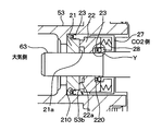
- FIG. 3 is a cross-sectional view of the contact surface between the rotating ring 22 and the shaft 63.
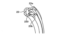
- FIG. 4 is a view showing a cross section of the U-ring 23 of the shaft seal device according to the present embodiment.
- the U-ring 23 is an annular seal member, and has a U-shape from an outer seal wall portion and an inner seal wall portion that face each other in the radial direction in a cross section, and a seal bottom portion that connects both seal wall portions.
- the seal bottom portion connects one end side of the shaft 63 positioned outside the front housing 53 at the outer seal wall portion and the inner seal wall portion.
- an annular opening is formed between the open end of the outer seal wall and the open end of the inner seal wall.
- a protrusion 23a and a protrusion 23b are formed on both sides (both open ends) in the radial direction of the opening. That is, the protrusion 23a is provided on the radially outer side of the open end of the outer seal wall, and the protrusion 23b is provided on the radially inner side of the open end of the inner seal wall.
- the protrusion 23a and the protrusion 23b protrude from both sides in the radial direction of the opening. More specifically, the protrusion 23a protrudes radially outward from the outer seal wall, and the protrusion 23b protrudes radially inward from the inner seal wall.
- the U ring 23 is made of PTFE (polytetrafluoroethylene) which is a fluorocarbon resin.
- the U-ring 23 is arranged so that the opening opens toward the refrigerant side inside the housing. That is, the U-ring 23 is provided so that the opening portion opens toward the side opposite to one end of the shaft 63 located outside the front housing 53.
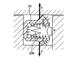
- the U-ring 23 has a dimensional structure in which the protrusions 23a and 23b are pressed against the seal surface by elasticity. That is, as shown in FIG. 5, when the pressure P of the refrigerant inside the housing increases, the U-ring 23 is elastically deformed to expand the opening, and the shaft 63 rotates with the protrusions 23a and 23b.
- the force F that holds down the ring 22 works. Thereby, the protrusions 23a and 23b seal the contact surface (seal surface) between the rotating ring 22 and the shaft 63 with a strong force.
- an annular metal spring member 230 is provided at the opening of the U-ring 23. This spring member 230 pushes and widens the opening of the U-ring 23. By the spring member 230, the protrusion 23a and the protrusion 23b of the U-ring 23 are more strongly pressed against the seal surface.
- the spring member 230 in the present embodiment has a W-shaped cross section.
- the spring member 230 expands the opening even when the pressure of the refrigerant inside the housing is low, and the protrusion 23a and the protrusion 23b are pressed against the seal surface.
- the spring 27 allows the rotation ring 22 to move in the axial direction of the shaft 63, so that the fixed-side seal end surface 21 a of the fixed ring 21 and the rotation-side seal of the rotation ring 22 are allowed. The seal of the end face 22a is maintained.
- the shaft seal device 20 satisfies the four requirements of heat resistance, foam resistance, carbon dioxide permeation resistance and cryogenic resistance. Is required.
- the two U rings 23 provided in the shaft seal device 20 of the present embodiment are each made of PTFE (polytetrafluoroethylene) which is a fluorocarbon resin.
- PTFE polytetrafluoroethylene
- FIG. 6 various characteristics comparison between various rubber materials and PTFE which is resin will be described.
- EPDM ethylene propylene rubber
- HNBR nitrile rubber
- VMQ silicone rubber
- FKM fluoro rubber
- the two U-rings 23 provided in the shaft seal device 20 of the present embodiment are made of PTFE (polytetrafluoroethylene) which is a flexible resin.
- PTFE polytetrafluoroethylene
- PTFE satisfies four requirements of heat resistance, carbon dioxide permeation resistance, foam resistance and cryogenic temperature.
- the shaft seal device 20 is provided with the U-ring 23 on each of the seal surface of the housing and the stationary ring 21 and the seal surface of the shaft 63 and the rotary ring 22.
- the U-ring 23 is disposed so that the opening portion opens toward the refrigerant side inside the housing, and the protrusions 23a and 23b formed on both sides in the radial direction of the opening portion are pressed against the sealing surface by elasticity.
- a resin that satisfies the four requirements of heat resistance, foam resistance, carbon dioxide permeation resistance and cryogenic resistance can be used.
- Such a resin U-ring 23 can satisfy, for example, four requirements of heat resistance, foam resistance, carbon dioxide permeation resistance and cryogenic resistance that cannot be satisfied by a rubber material. Further, the U-ring 23 is elastically deformed, so that the protrusions 23a and 23b are pressed against the seal surface. Thereby, the sealing performance of a sealing surface can be maintained over a long period of time.
- the rotary ring 22 biased by the spring 27 may move in the axial direction of the shaft 63 together with the shaft 63.
- PTFE polytetrafluoroethylene
- the U-ring 23 has a spring member 230 that pushes the opening of the U-ring 23, and the protrusions 23a and 23b are pressed against the seal surface by the spring member 230, so that the pressure of the refrigerant inside the housing is low. Even in this case, the sealing property can be ensured.
- the U-ring 23 in the first embodiment has a spring member 230 having a W-shaped cross section.
- the U-ring 24 in this embodiment has two annular plate-like spring members 240 and 241 having different diameters.
- the U-ring 24 is an annular seal member, and has a U-shape including an outer seal wall portion and an inner seal wall portion that are opposed in the radial direction in a cross section, and a seal bottom portion that couples both seal wall portions.
- the seal bottom portion connects one end side of the shaft 63 positioned outside the front housing 53 at the outer seal wall portion and the inner seal wall portion.
- an annular opening is formed between the open end of the outer seal wall and the open end of the inner seal wall.
- a protrusion 24a and a protrusion 24b are formed on both sides (both open ends) in the radial direction of the opening. That is, the protrusion 24a is provided on the radially outer side of the open end of the outer seal wall, and the protrusion 24b is provided on the radially inner side of the open end of the inner seal wall.
- the protrusion 24a and the protrusion 24b protrude from both sides in the radial direction of the opening. More specifically, the protrusion 24a protrudes radially outward from the outer seal wall, and the protrusion 24b protrudes radially inward from the inner seal wall.
- the spring members 240 and 241 are each composed of a thin metal plate formed in an annular shape, and are elastically deformed.
- the spring member 240 is disposed on the wall surface on the opposite side of the protruding portion 24a in the outer seal wall portion of the U-ring 24.
- the spring member 240 is slightly larger than the outer seal wall portion (the outer peripheral side surface of the opening) of the U ring 24 before being placed on the wall surface of the U ring 24.
- the diameter of the spring member 240 is slightly larger than the diameter of the opening of the U-ring 24 in a state before being arranged at the opening of the U-ring 24. Therefore, when arranged in the opening of the U-ring 24, a force acts radially outward as shown in FIG.
- the spring member 241 is disposed on the wall surface on the opposite side of the projecting portion 24b in the inner seal wall portion of the U ring 24.
- the spring member 241 is slightly smaller than the inner seal wall portion (the inner peripheral side surface of the opening) of the U ring 24 before being disposed on the wall surface of the U ring 24.
- the diameter of the spring member 241 is slightly smaller than the diameter of the opening of the U-ring 24 in a state before being arranged at the opening of the U-ring 24. Therefore, when arranged at the opening of the U-ring 24, a force acts radially inward as shown in FIG.
- These spring members 240 and 241 open the opening even when the pressure of the refrigerant inside the housing is low, and the protrusion 24a and the protrusion 24b are pressed against the seal surface.
- Such U-rings 24 are provided on the contact surface (seal surface) of the shaft hole 53b of the stationary ring 21 and the front housing 53, and on the contact surface (seal surface) of the rotary ring 22 and the shaft 63, respectively.
- the U-ring 24 including the spring members 240 and 241 formed of a metal thin plate in an annular shape as in the present embodiment can be reduced in cost because of its simple configuration. Miniaturization is also possible.
- this embodiment is embodiment based on 1st Embodiment, it is also possible to combine this embodiment with either of the above-mentioned 1st Embodiment.
- the spring member 230 of the U-ring 23 in the first embodiment is W-shaped in cross section.
- the spring member 250 of the U ring 25 in the present embodiment has a U shape in cross section.
- the U-ring 25 is an annular seal member, and has a U shape from an outer seal wall portion and an inner seal wall portion that are opposed in the radial direction in a cross section, and a seal bottom portion that couples both seal wall portions.
- the seal bottom portion connects one end side of the shaft 63 positioned outside the front housing 53 at the outer seal wall portion and the inner seal wall portion.
- an annular opening is formed between the open end of the outer seal wall and the open end of the inner seal wall.
- a protrusion 25a and a protrusion 25b are formed on both sides (both open ends) in the radial direction of the opening. That is, the protrusion 25a is provided on the radially outer side of the open end of the outer seal wall, and the protrusion 25b is provided on the radially inner side of the open end of the inner seal wall.
- the protrusion 25a and the protrusion 25b protrude from both sides in the radial direction of the opening. More specifically, the protrusion 25a protrudes radially outward from the outer seal wall, and the protrusion 25b protrudes radially inward from the inner seal wall.
- the spring member 250 is formed by forming a thin metal plate into an annular shape, and has a U-shape in cross section. When the spring member 250 is disposed at the opening of the U-ring 24, a force acts in the direction of opening the opening of the spring member 250 as shown in FIG.
- the spring member 250 expands the opening even when the pressure of the refrigerant inside the housing is low, and the protrusion 25a and the protrusion 25b are pressed against the seal surface.
- Such U-rings 25 are provided on the contact surface (seal surface) of the shaft hole 53b of the stationary ring 21 and the front housing 53, and on the contact surface (seal surface) of the rotary ring 22 and the shaft 63, respectively.
- the U-ring 25 including the spring member 250 having a U-shaped cross section as in the present embodiment has a simple configuration, the cost can be reduced, and the shaft seal device 20 can be downsized. Is possible.
- this embodiment is embodiment based on 1st Embodiment, it is also possible to combine this embodiment with either of the above-mentioned 1st Embodiment.
- the compressor of the present disclosure has been described by taking a swash plate compressor using carbon dioxide as a refrigerant as an example, but can be applied to various compressors other than the swash plate compressor. .
- the balance type shaft seal device has been described as an example.
- the present invention is not limited to such a type shaft seal device.
- an unbalanced shaft seal device may be used. It can also be applied.
- the U-rings 23, 24, and 25 have a U-shaped cross section, but may have a V-shaped cross section, for example.
- spring members 230, 240, 241, and 250 are provided at the openings of the U-rings 23, 24, and 25. However, it is not always necessary to provide such a spring member.
- the U-rings 23, 24, and 25 are made of PTFE (polytetrafluoroethylene).
- PTFE polytetrafluoroethylene
- the U-ring 23 of the first embodiment includes a spring member 230 having a W-shaped cross section
- the U-ring 25 of the second embodiment includes a spring member 250 having a U-shaped cross section
- the U-ring may be provided with a spring member having a V-shaped cross section.
- U rings 23, 24, and 25 are provided on both the seal surfaces of the front housing 53 and the stationary ring 21 and the seal surfaces of the shaft 63 and the rotating ring 22.
- the U rings 23, 24, and 25 may be provided on any one of the seal surface of the front housing 53 and the stationary ring 21 and the seal surface of the shaft 63 and the rotating ring 22.
- a U-ring may be provided on the seal surfaces of the shaft 63 and the rotary ring 22, and for example, the seal surfaces of the front housing 53 and the fixed ring 21 may be joined so that the sealing performance is maintained.
- the U rings 23, 24, and 25 are provided on the contact surface of the stationary ring 21 with the front housing 53.
- the U ring 23 is disposed on the contact surface of the front housing 53 with the stationary ring 21.
- 24, 25 may be provided.
- the U-rings 23, 24, 25 are provided on the contact surface of the rotating ring 22 with the shaft 63.
- the U-rings 23, 24 are provided on the contact surface of the shaft 63 with the rotating ring 22. 25 may be provided.
- the present disclosure is not limited to the above-described embodiment, and can be appropriately changed without departing from the gist of the present disclosure.
- the material, shape, positional relationship, etc. of the constituent elements, etc. when referring to the material, shape, positional relationship, etc. of the constituent elements, etc., unless otherwise specified, or in principle limited to a specific material, shape, positional relationship, etc.
- the material, shape, positional relationship, etc. are not limited.
Landscapes
- Engineering & Computer Science (AREA)
- General Engineering & Computer Science (AREA)
- Mechanical Engineering (AREA)
- Compressor (AREA)
- Sealing With Elastic Sealing Lips (AREA)
- Gasket Seals (AREA)
- Mechanical Sealing (AREA)
Abstract
軸封装置は、二酸化炭素の冷媒を圧縮する圧縮機(51)に用いられる。軸封装置は、回転環(22)と固定環(21)を備える。回転環は、冷媒を収容するハウジング(53、55、57)の内側に位置するシャフト(63)に固定される。固定環は、ハウジングに形成された軸孔(53b)に固定され、軸孔に挿通されたシャフトを回転可能に支持する。ハウジングと固定環のシール面およびシャフトと回転環のシール面のうち少なくとも一方には、開口部を有し、該開口部の径方向における両側に突起部(23a、24a、25a、23b、24b、25b)が形成された環状のシール部材(23、24、25)が設けられている。シール部材は、開口部がハウジングの内部の冷媒側を向いて開口するように配置され、突起部が弾性によりシール面に押し付けられる。
Description
本出願は、当該開示内容が参照によって本出願に組み込まれた、2014年12月25日に出願された日本特許出願2014-262228号を基にしている。
本開示は、軸封装置およびそれを用いた圧縮機に関するものである。
一般的な圧縮機は、シャフトの回転によりハウジング内の流体に流体圧を発生させる圧縮機構を有している。このような圧縮機は、ハウジングとシャフトの隙間からハウジングの外部へ流体が漏れ出るのを防止する軸封装置を備えている。
近年、このような圧縮機では、フロンに変わる二酸化炭素(CO2)が冷媒ガスとして採用されつつある。このような冷媒ガスを採用した場合、軸封装置に作用する圧力がフロンを用いた場合よりも10倍以上となることがある。その場合、軸封装置への負荷が大きく、軸封装置の耐久性の低下が一層生じやすくなる。
耐久性の向上を目的とした軸封装置として、固定環、回転環、パッキン(Oリング)、およびバネを備えた軸封装置がある(例えば、特許文献1参照)。固定環は、軸孔に固定され、環状をなして固定環の作用部側に固定側シール端面を有している。回転環は、ハウジング内に位置するシャフトに固定され、環状をなして回転環の受動部側に固定側シール端面と摺接する回転側シール端面を有している。パッキンは、シャフトに固定され、環状をなしてシャフトと回転環の隙間を封止する。バネは、シャフトに固定され、回転環をハウジング外へ軸方向に押圧する。
本開示の発明者らによる検討によると、上記特許文献1に記載されたような圧縮機の軸封装置では、固定側シール端面と回転側シール端面が摺動するようになっており、この摺動する部分で摩擦熱が発生する。また、二酸化炭素を採用した場合、軸封装置の周囲温度はフロンガスを用いた場合よりも高温になる。したがって、このような軸封装置は、耐熱性に優れていることが求められる。
また、このような圧縮機は、作動時に軸封装置の周囲圧力が常に大きく変動する。また、このような圧縮機では、作動時に二酸化炭素の冷媒の圧力によってシャフトと回転環の隙間を封止するパッキンの内部に冷媒が繰り返し出入りする。このとき、高圧環境下でパッキンの内部に浸透した冷媒ガスが、減圧時等にパッキン内部で膨張する過程を繰り返し、パッキンに亀裂等が発生する発泡現象が生じる。このような現象が生じることのないよう、このような圧縮機の軸封装置は、耐発泡性に優れていることが求められる。
また、二酸化炭素の分子量はフロンと比較して低くなっている。このため、このような圧縮機では、非常に透過性が高く、シャフトと回転環の隙間を封止するパッキンを透過して二酸化炭素がハウジングの外に漏れやすい。このような現象が生じないよう、このような圧縮機の軸封装置は、二酸化炭素耐透過性に優れていることも求められる。
また、車両用空調装置に搭載される圧縮機は、極低温の状態で使用される場合もある。このため、このような圧縮機の軸封装置は、極低温でも気密性を確保できるようにすることも求められる。
上記したように、このような圧縮機の軸封装置では、耐熱性、耐発泡性、二酸化炭素耐透過性および耐極低温性に優れていることが求められる。
しかしながら、特許文献1に記載された圧縮機は、パッキン(Oリング)によりシャフトと回転環の接触面(シール部)を封止する構成となっている。このようなパッキンは一般的にゴム材で構成される。しかし、ゴム材を用いてパッキンを構成した場合、耐熱性、耐発泡性、二酸化炭素耐透過性および耐極低温性の4つの要件を満たすのは困難であり、長期間にわたってシール面のシール性を維持するのは難しい。
本開示は上記点に鑑みたもので、より長期間にわたってシール面のシール性を維持できる軸封装置およびそれを用いた圧縮機を提供することを目的とする。
本開示の軸封装置は、二酸化炭素の冷媒を圧縮する圧縮機に用いられる。軸封装置は、回転環と固定環を備える。回転環は、冷媒を収容するハウジングの内側に位置するシャフトに固定される。固定環は、ハウジングに形成された軸孔に固定され、軸孔に挿通されたシャフトを回転可能に支持する。ハウジングと固定環のシール面およびシャフトと回転環のシール面のうち少なくとも一方には、開口部を有し、該開口部の径方向における両側に突起部が形成された環状のシール部材が設けられている。シール部材は、開口部がハウジングの内部の冷媒側を向いて開口するように配置され、突起部が弾性によりシール面に押し付けられる。
ここで、シール部材は、耐熱性、耐発泡性、二酸化炭素耐透過性および耐極低温性の4つの要件を満たす樹脂を用いることができる。このような樹脂製のシール部材は、例えば、ゴム材では満たすことのできない耐熱性、耐発泡性、二酸化炭素耐透過性および耐極低温性の4つの要件を満たすことができ、更に、弾性変形して開口部の両外側に形成された突起部がシール面に押し付けられるようにすることができるため、より長期間にわたってシール面のシール性を維持することができる。
本開示の圧縮機は、上述した軸封装置を、シャフトの周囲の密封に用いている。
本開示についての上記目的およびその他の目的、特徴や利点は、添付の図面を参照しながら下記の詳細な記述により、より明確になる。
第1実施形態に係る圧縮機の縦断面図である。
図1中のZ部の拡大図である。
第1実施形態に係る軸封装置の回転環とシャフトの接触面の断面図である。
第1実施形態に係る軸封装置のUリングの断面の様子を示した図である。
Uリングの作動について説明するための図である。
二酸化炭素の冷媒使用時の各種ゴム材料の特性を比較した図である。
第2実施形態に係る軸封装置のUリングの構成を示した図である。
図7に示すUリングに用いられるバネ部材を示す図である。
第3実施形態に係る軸封装置のUリングの構成を示した図である。
図9に示すUリングに用いられるバネ部材を示す図である。
以下に、図面を参照しながら本開示を実施するための複数の実施形態を説明する。各実施形態において先行する実施形態で説明した事項に対応する部分には同一の参照符号を付して重複する説明を省略する場合がある。各実施形態において構成の一部のみを説明している場合は、構成の他の部分については先行して説明した実施形態と同様とする。各実施形態で具体的に説明している部分の組合せばかりではなく、特に組合せに支障が生じなければ、実施形態同士を部分的に組み合せることも可能である。
(第1実施形態)
以下、第1実施形態に係る圧縮機および軸封装置について、図1から図6を参照して説明する。本実施形態に係る圧縮機は、駆動軸の中心線に対して傾斜して配置された斜板の傾斜角度を変化させることで、往復運動するピストンの行程を変化させて圧縮機の吐出容量を変化させる斜板型圧縮機51として構成されている。斜板型圧縮機51は、二酸化炭素の冷媒を圧縮する圧縮機である。斜板型圧縮機51は、例えば、自動車等の空調装置に適用される。
以下、第1実施形態に係る圧縮機および軸封装置について、図1から図6を参照して説明する。本実施形態に係る圧縮機は、駆動軸の中心線に対して傾斜して配置された斜板の傾斜角度を変化させることで、往復運動するピストンの行程を変化させて圧縮機の吐出容量を変化させる斜板型圧縮機51として構成されている。斜板型圧縮機51は、二酸化炭素の冷媒を圧縮する圧縮機である。斜板型圧縮機51は、例えば、自動車等の空調装置に適用される。
また、斜板型圧縮機51は、有底筒状のフロントハウジング53を有している。この有底筒状のフロントハウジング53の開口部には、この開口部を塞ぐようにシリンダブロック55が設けられている。シリンダブロック55には、リアハウジング57が設けられている。フロントハウジング53の底壁53aの中央部とシリンダブロック55の中央部には、それぞれラジアルベアリング59、61が設けられている。ラジアルベアリング59、61間に、シャフト63が軸支されている。なお、フロントハウジング53とシリンダブロック55とリアハウジング57により冷媒を収容するハウジングが構成される。
また、フロントハウジング53の底壁53aでラジアルベアリング59より前側(図中、左側)には、メカニカルシールと呼ばれる軸封装置20が設けられている。この軸封装置20は、フロントハウジング53とシャフト63の隙間からフロントハウジング53の外部に冷媒が漏れ出るのを防止する。この軸封装置20については、後で詳細に説明する。
フロントハウジング53の底壁53a上には、シャフト63に固定された円盤状のラグプレート73が設けられている。このラグプレート73と底壁53aとの間には、スラスト軸受75が介装されており、ピストン圧縮反力による軸方向荷重を受けている。
シャフト63のラグプレート73とシリンダブロック55との間には、斜板77がシャフト63の軸方向に対して回転可能に設けられている。この斜板77とラグプレート73とは、ラグプレート73に設けられたリンク機構部79と、斜板77に設けられたピン81によって、傾角可能に連結されており、ラグプレート73の回転を斜板77に伝達する。
シリンダブロック55には、周方向に等間隔に離間してシリンダボア83が形成されている。このシリンダボア83は、シャフト63の軸線に平行に配設されており、その内部にはピストン85が往復動可能に挿入されている。
このピストン85には球面軸受87が設けられている。この球面軸受87には、斜板77の外周部を周方向に摺動可能に把持した一対のシュー89が係合している。
シリンダブロック55とリアハウジング57との間にはバルブプレート91が介装されている。バルブプレート91とシリンダブロック55との間には、吸入弁93が設けられており、吸入ポートをシールする。
リアハウジング57の内側には、吸入室95と吐出室97が設けられている。バルブプレート91のリアハウジング57側の吐出室97には、吐出弁99と弁リフト量を規制するリテーナ101がボルト等によってバルブプレート91に締結されている。
リアハウジング57には、制御弁103が設けられており、斜板室71に制御ガスを導入して斜板の傾き角を調整し、吐出容量を設定する。なお、制御弁103から斜板室71へ制御ガスを導入する通路は、シリンダブロック55、リアハウジング57、バルブプレート91等に形成されるがここでは図示しない。
次に、本実施形態の軸封装置20について説明する。軸封装置20は、シャフト63の周囲を密封するものである。また、軸封装置20は、バランス型の軸封装置である。軸封装置20は、フロントハウジング53の底壁53aの中央部に形成された軸孔53bに設けられている。図2に示すように、軸封装置20は、固定環21、回転環22、スプリング27およびブラケット28を有している。
固定環21は、例えば、シリコンカーバイト製であり、軸孔53bに固定されている。その軸孔53bはフロントハウジング53に形成されている。固定環21は軸孔53bに挿通されたシャフト63を回転可能に支持する。シャフト63は、軸孔53bを介してフロントハウジング53を貫通している。シャフト63の一端は、フロントハウジング53の外側に位置している。また、固定環21は、環状をなしており、回転環22に隣接する側(図中、右側)に固定側シール端面21aを有している。
回転環22は、例えば、カーボン製であり、フロントハウジング53の内側に位置するシャフト63に固定されている。回転環22は、環状をなしており、固定環21に隣接する側(図中、左側)に回転側シール端面22aを有している。回転環22は、シャフト63と一体となって回転する。
スプリング27は、たとえばコイルバネであり、シャフト63にブラケット28を介して固定されている。また、スプリング27は、回転環22をフロントハウジング53の前側(図中、左側)へ軸方向に付勢する。
ブラケット28は、スプリング27の座面を形成する。ブラケット28は、シャフト63に固定され、シャフト63と回転環22と一体的に回転する。
また、固定環21とフロントハウジング53のハウジングの軸孔53bの接触面(シール面)と、回転環22とシャフト63の接触面(シール面)には、それぞれシール部材に相当するUリング23が設けられている。
具体的には、固定環21の外周面にはUリング挿入溝210が形成されている。Uリング挿入溝210には、柔軟性を有する樹脂製のUリング23が配置されている。このUリング23により固定環21とフロントハウジング53の軸孔53bの接触面(シール面)がシールされる。
また、回転環22の内周面にはUリング挿入溝220が形成されている。Uリング挿入溝220にも、柔軟性を有する樹脂製のUリング23が配置されている。このUリング23により回転環22とシャフト63の接触面(シール面)がシールされる。各Uリング23の構成および材質は同一となっている。
図3は、回転環22とシャフト63の接触面の断面図である。また、図4は、本実施形態に係る軸封装置のUリング23の断面を示した図である。Uリング23は環状のシール部材であり、断面において径方向に対向する外側シール壁部および内側シール壁部と、両シール壁部を連結するシール底部とからU字形状をなしている。シール底部は、外側シール壁部および内側シール壁部において、フロントハウジング53の外側に位置するシャフト63の一端側を連結している。一方、外側シール壁部の開放端部および内側シール壁部の開放端部の間には、環状の開口部が形成されている。
図3に示すUリング23の断面において、開口部の径方向における両側(両開放端部)には、突起部23aと突起部23bが形成されている。すなわち、外側シール壁部の開放端部の径方向外側に突起部23aが設けられ、内側シール壁部の開放端部の径方向内側に突起部23bが設けられている。突起部23aおよび突起部23bは、開口部の径方向における両側から突起している。より詳細には、突起部23aは、外側シール壁部から径方向の外側に突出し、突起部23bは、内側シール壁部から径方向の内側に突出している。
Uリング23は、フッ化炭素樹脂であるPTFE(ポリテトラフルオロエチレン)により構成されている。
Uリング23は、開口部がハウジングの内部の冷媒側を向いて開口するように配置されている。すなわち、Uリング23は、開口部がシャフト63におけるフロントハウジング53の外側に位置する一端とは反対側に向けて開口するよう設けられる。Uリング23は、突起部23a、23bが弾性によりシール面に押し付けられる寸法構造となっている。すなわち、Uリング23は、図5に示すように、ハウジングの内部の冷媒の圧力Pが高くなるとUリング23が弾性変形して開口部が広がり、突起部23aと突起部23bにシャフト63と回転環22を押さえ付ける力Fが働きく。これにより、突起部23a、23bが、回転環22とシャフト63の接触面(シール面)を強い力でシールする。
また、Uリング23の開口部には、環状をなす金属製のバネ部材230が設けられている。このバネ部材230は、Uリング23の開口部を押し広げる。このバネ部材230によって、Uリング23の突起部23aと突起部23bがより強くシール面に押し付けられる。
なお、本実施形態におけるバネ部材230は、断面がW形状となっている。このバネ部材230により、ハウジングの内部の冷媒の圧力が低い場合でも開口部が広がり、突起部23aと突起部23bがシール面に押し付けられる。
上記した構成において、シャフト63を外部駆動力(例えば車両エンジン)により回転すると、シャフト63に固定されたラグプレート73が回転し、ピン81とリンク機構部79によって連結された斜板77が回転する。ここで、斜板77の外周部はシュー89によって周方向摺動自在に把持されており、シュー89は、ピストン85の球面軸受に揺動自在に係合されている。したがって、斜板77の回転揺動運動はピストン85の往復運動に変換され、シリンダ内の流体が吐出、あるいは吸入される。
このような斜板型圧縮機51の軸封装置20では、(A)固定側シール端面21aと回転側シール端面22aの接触面、(B)回転環22とシャフト63の接触面、(C)固定環21とフロントハウジング53のハウジングの軸孔53bの接触面の3箇所において、外部への冷媒の漏洩を防止するシール部分が生じる。以下、(A)から(C)に示したシールについて説明する。
(A)固定側シール端面21aと回転側シール端面22aの接触面のシール
シャフト63が回転すると、固定環21の固定側シール端面21aと、回転環22の回転側シール端面22aとがスプリング27及び圧縮機の冷媒内圧により押圧されつつ摺動する。なお、冷媒として使用される二酸化炭素の冷媒には潤滑油が混入されている。潤滑油が固定環21の固定側シール端面21aと回転環22の回転側シール端面22aの接触面に引き込まれることで、油膜が形成される。このように、固定側シール端面21aと回転側シール端面22aの微小隙間が潤滑油で満たされ、ハウジング内の冷媒が外部に漏れないようシールされる。
シャフト63が回転すると、固定環21の固定側シール端面21aと、回転環22の回転側シール端面22aとがスプリング27及び圧縮機の冷媒内圧により押圧されつつ摺動する。なお、冷媒として使用される二酸化炭素の冷媒には潤滑油が混入されている。潤滑油が固定環21の固定側シール端面21aと回転環22の回転側シール端面22aの接触面に引き込まれることで、油膜が形成される。このように、固定側シール端面21aと回転側シール端面22aの微小隙間が潤滑油で満たされ、ハウジング内の冷媒が外部に漏れないようシールされる。
また、シャフト63が軸方向に変位してもスプリング27により回転環22のシャフト63の軸方向への移動が許容されるため、固定環21の固定側シール端面21aと回転環22の回転側シール端面22aのシールは維持される。
(B)回転環22とシャフト63の接触面のシール
シャフト63と回転環22の接触面(シール面)には、断面においてU字形状を有する環状のUリング23が設けられている。本実施形態では、Uリング23は樹脂製である。Uリング23は、開口部の径方向における両側に突起部23a、23bを有している。突起部23a、23bが弾性によりシール面に押し付けられ、シャフト63と回転環22のシール面がシールされる。
シャフト63と回転環22の接触面(シール面)には、断面においてU字形状を有する環状のUリング23が設けられている。本実施形態では、Uリング23は樹脂製である。Uリング23は、開口部の径方向における両側に突起部23a、23bを有している。突起部23a、23bが弾性によりシール面に押し付けられ、シャフト63と回転環22のシール面がシールされる。
(C)固定環21とフロントハウジング53の軸孔53bの接触面のシール
固定環21とフロントハウジング53の軸孔53bの接触面(シール面)には、開口部の両外側に突起部23a、23bが形成された断面U字形状の環状の樹脂製のUリング23が設けられている。突起部23a、23bが弾性によりシール面に押し付けられ、固定環21とフロントハウジング53の軸孔53bのシール面がシールされる。
固定環21とフロントハウジング53の軸孔53bの接触面(シール面)には、開口部の両外側に突起部23a、23bが形成された断面U字形状の環状の樹脂製のUリング23が設けられている。突起部23a、23bが弾性によりシール面に押し付けられ、固定環21とフロントハウジング53の軸孔53bのシール面がシールされる。
斜板型圧縮機51は、二酸化炭素を冷媒として採用しているため、軸封装置20においては、耐熱性、耐発泡性、二酸化炭素耐透過性および耐極低温性の4つの要件を満たすことが求められる。
本実施形態の軸封装置20に設けられた2つのUリング23は、それぞれフッ化炭素樹脂であるPTFE(ポリテトラフルオロエチレン)により構成されている。ここで、図6を参照して、各種ゴム材と樹脂であるPTFEの各種特性比較について説明する。
EPDM(エチレンプロピレンゴム)は、耐熱性、二酸化炭素耐透過性、耐発泡性および極低温性のいずれも劣る。また、高温用HNBR(ニトリルゴム)は、耐熱性、二酸化炭素耐透過性および極低温性に優れているものの耐発泡性に劣る。また、VMQ(シリコーンゴム)は、耐熱性、耐発泡性および極低温性に優れているものの二酸化炭素耐透過性に劣る。また、FKM(フッ素ゴム)は、耐熱性および二酸化炭素耐透過性に優れているが、耐発泡性および極低温性は劣る。このように、ゴム剤では、耐熱性、二酸化炭素耐透過性、耐発泡性および極低温性の4つの要求を満たすことはできない。
これに対し、本実施形態の軸封装置20に設けられた2つのUリング23は、柔軟性を有する樹脂であるPTFE(ポリテトラフルオロエチレン)により構成されている。PTFEは、耐熱性、二酸化炭素耐透過性、耐発泡性および極低温性の4つの要件を満たしている。
上記した構成によれば、軸封装置20は、ハウジングと固定環21のシール面およびシャフト63と回転環22のシール面のそれぞれにUリング23が設けられている。Uリング23は、開口部がハウジングの内部の冷媒側を向いて開口するように配置され、開口部の径方向における両側に形成された突起部23a、23bが弾性によりシール面に押し付けられる。Uリング23を形成する材料として、耐熱性、耐発泡性、二酸化炭素耐透過性および耐極低温性の4つの要件を満たす樹脂を用いることができる。このような樹脂製のUリング23は、例えば、ゴム材では満たすことのできない耐熱性、耐発泡性、二酸化炭素耐透過性および耐極低温性の4つの要件を満たすことができる。更に、Uリング23が弾性変形することで、突起部23a、23bがシール面に押し付けられる。これにより、長期間にわたってシール面のシール性を維持することができる。
また、シャフト63と回転環22のシール面では、スプリング27に付勢された回転環22がシャフト63とともにシャフト63の軸方向に移動する場合があるが、このようなシャフト63と回転環22のシール面にUリング23を設けることで、効果的にシールを行うことが可能である。
また、耐熱性、耐発泡性、二酸化炭素耐透過性および耐極低温性の4つの要件を満たすことができる樹脂としては、例えば、PTFE(ポリテトラフルオロエチレン)を用いることができる。
また、Uリング23は、Uリング23の開口部を押し広げるバネ部材230を有し、該バネ部材230により突起部23a、23bがシール面に押し付けられるので、ハウジングの内部の冷媒の圧力が低い場合でも、シール性を確保することができる。
(第2実施形態)
以下、第2実施形態に係る圧縮機および軸封装置について、図7、図8を参照して説明する。第1実施形態におけるUリング23は、断面がW字形状となっているバネ部材230を有している。これに対し、本実施形態におけるUリング24は、直径の異なる2つの円環板状のバネ部材240、241を有している。
以下、第2実施形態に係る圧縮機および軸封装置について、図7、図8を参照して説明する。第1実施形態におけるUリング23は、断面がW字形状となっているバネ部材230を有している。これに対し、本実施形態におけるUリング24は、直径の異なる2つの円環板状のバネ部材240、241を有している。
Uリング24は、環状のシール部材であり、断面において径方向に対向する外側シール壁部および内側シール壁部と、両シール壁部を連結するシール底部とからU字形状をなしている。シール底部は、外側シール壁部および内側シール壁部において、フロントハウジング53の外側に位置するシャフト63の一端側を連結している。一方、外側シール壁部の開放端部および内側シール壁部の開放端部の間には、環状の開口部が形成されている。
図7に示すUリング24の断面において、開口部の径方向における両側(両開放端部)には、突起部24aと突起部24bが形成されている。すなわち、外側シール壁部の開放端部の径方向外側に突起部24aが設けられ、内側シール壁部の開放端部の径方向内側に突起部24bが設けられている。突起部24aおよび突起部24bは、開口部の径方向における両側から突起している。より詳細には、突起部24aは、外側シール壁部から径方向の外側に突出し、突起部24bは、内側シール壁部から径方向の内側に突出している。
バネ部材240、241はそれぞれ、円環状に形成した金属製の薄板により構成され、弾性変形する。
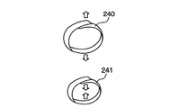
バネ部材240は、Uリング24の外側シール壁部のうち、突起部24aとは反対側の壁面に配置される。バネ部材240は、Uリング24の当該壁面に配置される前の状態において、Uリング24の外側シール壁部(開口部の外周側側面)よりも僅かに大きくなっている。換言すると、バネ部材240の直径は、Uリング24の開口部に配置される前の状態において、Uリング24の開口部の直径よりも僅かに大きい。したがって、Uリング24の開口部に配置されると、図8に示すように、径方向外側に向けて力が作用する。
また、バネ部材241は、Uリング24の内側シール壁部のうち、突起部24bとは反対側の壁面に配置される。バネ部材241は、Uリング24の当該壁面に配置される前の状態において、Uリング24の内側シール壁部(開口部の内周側側面)よりも僅かに小さくなっている。還元すると、バネ部材241の直径は、Uリング24の開口部に配置される前の状態において、Uリング24の開口部の直径よりも僅かに小さい。したがって、Uリング24の開口部に配置されると、図8に示すように、径方向内側に向けて力が作用する。
これらのバネ部材240、241により、ハウジングの内部の冷媒の圧力が低い場合でも開口部が広がり、突起部24aと突起部24bがシール面に押し付けられる。
このようなUリング24が、固定環21とフロントハウジング53のハウジングの軸孔53bの接触面(シール面)と、回転環22とシャフト63の接触面(シール面)にそれぞれ設けられている。
本実施形態では、第1実施形態と共通の構成から奏される効果を第1実施形態と同様に得ることができる。
また、本実施形態のような金属製の薄板を円環状に形成したバネ部材240、241を備えたUリング24は、構成が簡素であるため低コスト化が可能であり、軸封装置20の小型化も可能である。
なお、本実施形態は第1実施形態に基づいた実施形態であるが、本実施形態を前述の第1実施形態のうちの何れかと組み合わせることも可能である。
(第3実施形態)
以下、第3実施形態に係る圧縮機および軸封装置について、図9、図10を参照して説明する。第1実施形態におけるUリング23のバネ部材230は、断面においてW字形状となっている。これに対し、本実施形態におけるUリング25のバネ部材250は、断面においてU字形状となっている。
以下、第3実施形態に係る圧縮機および軸封装置について、図9、図10を参照して説明する。第1実施形態におけるUリング23のバネ部材230は、断面においてW字形状となっている。これに対し、本実施形態におけるUリング25のバネ部材250は、断面においてU字形状となっている。
Uリング25は、環状のシール部材であり、断面において径方向に対向する外側シール壁部および内側シール壁部と、両シール壁部を連結するシール底部とからU字形状をなしている。シール底部は、外側シール壁部および内側シール壁部において、フロントハウジング53の外側に位置するシャフト63の一端側を連結している。一方、外側シール壁部の開放端部および内側シール壁部の開放端部の間には、環状の開口部が形成されている。
図9に示すUリング25の断面において、開口部の径方向における両側(両開放端部)には、突起部25aと突起部25bが形成されている。すなわち、外側シール壁部の開放端部の径方向外側に突起部25aが設けられ、内側シール壁部の開放端部の径方向内側に突起部25bが設けられている。突起部25aおよび突起部25bは、開口部の径方向における両側から突起している。より詳細には、突起部25aは、外側シール壁部から径方向の外側に突出し、突起部25bは、内側シール壁部から径方向の内側に突出している。
バネ部材250は、金属製の薄板を円環状に形成して構成されており、断面においてU字形状を有している。バネ部材250は、Uリング24の開口部に配置されると、図10に示すように、バネ部材250の開口部を開口させる方向に力が作用する。
このバネ部材250により、ハウジングの内部の冷媒の圧力が低い場合でも開口部が広がり、突起部25aと突起部25bがシール面に押し付けられる。
このようなUリング25が、固定環21とフロントハウジング53のハウジングの軸孔53bの接触面(シール面)と、回転環22とシャフト63の接触面(シール面)にそれぞれ設けられている。
本実施形態では、第1実施形態と共通の構成から奏される効果を第1実施形態と同様に得ることができる。
また、本実施形態のような断面がU字形状となっているバネ部材250を備えたUリング25は、構成が簡素であるため低コスト化が可能であり、軸封装置20の小型化も可能である。
なお、本実施形態は第1実施形態に基づいた実施形態であるが、本実施形態を前述の第1実施形態のうちの何れかと組み合わせることも可能である。
(他の実施形態)
第1から第3実施形態では、本開示の圧縮機について、二酸化炭素を冷媒とした斜板型圧縮機を例に説明したが、斜板型圧縮機以外の各種圧縮機に適用することができる。
第1から第3実施形態では、本開示の圧縮機について、二酸化炭素を冷媒とした斜板型圧縮機を例に説明したが、斜板型圧縮機以外の各種圧縮機に適用することができる。
また、第1から第3実施形態では、バランス型の軸封装置を例に説明したが、このような型の軸封装置に限定されるものではなく、例えば、アンバランス型の軸封装置に適用することもできる。
また、第1から第3実施形態では、Uリング23、24、25は断面がU字形状となっているが、例えば、断面がV字形状となっているようにしてもよい。
また、第1から第3実施形態では、Uリング23、24、25の開口部には、バネ部材230、240、241、250が設けられている。しかしながら、必ずしもこのようなバネ部材を設ける必要はない。
また、第1から第3実施形態では、Uリング23、24、25をPTFE(ポリテトラフルオロエチレン)により構成した。しかしながら、PTFE以外の耐熱性、耐発泡性、二酸化炭素耐透過性および耐極低温性の4つの要件を満たす樹脂により構成してもよい。
また、第1実施形態のUリング23は、断面形状がW字形状のバネ部材230を備え、第2実施形態のUリング25は、断面形状がU字形状のバネ部材250を備えている。しかしながら、例えば、Uリングに、断面形状がV字形状のバネ部材を備えるようにしてもよい。
また、第1から第3実施形態では、フロントハウジング53と固定環21のシール面およびシャフト63と回転環22のシール面の両方のシール面にUリング23、24、25を設けた。しかしながら、フロントハウジング53と固定環21のシール面およびシャフト63と回転環22のシール面のいずれか一方にUリング23、24、25を設けてもよい。また、シャフト63と回転環22のシール面にUリングを設け、例えば、フロントハウジング53と固定環21のシール面はシール性が維持されるよう接合してもよい。
また、第1から第3実施形態では、固定環21におけるフロントハウジング53との接触面にUリング23、24、25を設けたが、フロントハウジング53における固定環21との接触面にUリング23、24、25を設けてもよい。また、第1、第2実施形態では、回転環22におけるシャフト63との接触面にUリング23、24、25を設けたが、シャフト63における回転環22との接触面にUリング23、24、25を設けてもよい。
なお、本開示は上記した実施形態に限定されるものではなく、本開示の趣旨を逸脱しない範囲内において適宜変更が可能である。また、上記各実施形態において、構成要素等の材質、形状、位置関係等に言及するときは、特に明示した場合および原理的に特定の材質、形状、位置関係等に限定される場合等を除き、その材質、形状、位置関係等に限定されるものではない。
Claims (7)
- 二酸化炭素の冷媒を圧縮する圧縮機(51)の軸封装置であって、
前記冷媒を収容するハウジング(53、55、57)の内側に位置するシャフト(63)に固定される回転環(22)と、
前記ハウジングに形成された軸孔(53b)に固定され、前記軸孔に挿通された前記シャフトを回転可能に支持する固定環(21)と、を備え、
前記ハウジングと前記固定環のシール面および前記シャフトと前記回転環のシール面のうち少なくとも一方には、開口部を有し、該開口部の径方向における両側に突起部(23a、24a、25a、23b、24b、25b)が形成された環状のシール部材(23、24、25)が設けられており、
前記シール部材は、前記開口部が前記ハウジングの内部の前記冷媒側を向いて開口するように配置され、前記突起部が弾性により前記シール面に押し付けられる軸封装置。 - 前記シール部材は、断面U字形状をなすUリングである請求項1に記載の軸封装置。
- 前記シール部材は、前記シャフトと前記回転環のシール面に設けられている請求項1または2に記載の軸封装置。
- 前記シール部材は、PTFEで構成されている請求項1ないし3のいずれか1つに記載の軸封装置。
- 前記シール部材は、前記シール部材の前記開口部を押し広げるバネ部材(230、240、241、250)を有し、
前記バネ部材により前記突起部が前記シール面に押し付けられる請求項1ないし4のいずれか1つに記載の軸封装置。 - 前記バネ部材は、断面形状がU字、V字、W字のいずれかとなっている請求項5に記載の軸封装置。
- 請求項1ないし6のいずれか1つに記載の軸封装置を、前記シャフトの周囲の密封に用いている圧縮機。
Applications Claiming Priority (2)
| Application Number | Priority Date | Filing Date | Title |
|---|---|---|---|
| JP2014-262228 | 2014-12-25 | ||
| JP2014262228A JP2016121762A (ja) | 2014-12-25 | 2014-12-25 | 軸封装置および圧縮機 |
Publications (1)
| Publication Number | Publication Date |
|---|---|
| WO2016103601A1 true WO2016103601A1 (ja) | 2016-06-30 |
Family
ID=56149671
Family Applications (1)
| Application Number | Title | Priority Date | Filing Date |
|---|---|---|---|
| PCT/JP2015/006087 Ceased WO2016103601A1 (ja) | 2014-12-25 | 2015-12-08 | 軸封装置およびそれを用いた圧縮機 |
Country Status (2)
| Country | Link |
|---|---|
| JP (1) | JP2016121762A (ja) |
| WO (1) | WO2016103601A1 (ja) |
Cited By (3)
| Publication number | Priority date | Publication date | Assignee | Title |
|---|---|---|---|---|
| EP3944758A1 (de) * | 2020-07-30 | 2022-02-02 | BSH Hausgeräte GmbH | Abdichtungsring für ein pflanzenkultivierungssystem sowie pflanzenkultivierungssystem mit abdichtungsring |
| CN115280043A (zh) * | 2020-03-31 | 2022-11-01 | Nok株式会社 | 密封结构 |
| US20230028144A1 (en) * | 2019-12-11 | 2023-01-26 | Ntn Corporation | Shaft seal |
Families Citing this family (2)
| Publication number | Priority date | Publication date | Assignee | Title |
|---|---|---|---|---|
| JP7383355B2 (ja) * | 2020-04-09 | 2023-11-20 | イーグル工業株式会社 | 金属ガスケット |
| WO2023233969A1 (ja) * | 2022-06-01 | 2023-12-07 | 伸和コントロールズ株式会社 | 流量制御用三方弁及び温度制御装置 |
Citations (6)
| Publication number | Priority date | Publication date | Assignee | Title |
|---|---|---|---|---|
| JPS56149164U (ja) * | 1980-04-10 | 1981-11-09 | ||
| JPH0280863A (ja) * | 1988-09-13 | 1990-03-20 | Natl Space Dev Agency Japan<Nasda> | 高剛性シールリング |
| JP2007092546A (ja) * | 2005-09-27 | 2007-04-12 | Toshiba Kyaria Kk | 流体機械 |
| JP2008111391A (ja) * | 2006-10-31 | 2008-05-15 | Sanden Corp | 圧縮機 |
| WO2009093460A1 (ja) * | 2008-01-23 | 2009-07-30 | Valeo Thermal Systems Japan Corporation | 圧縮機の軸封構造 |
| JP2012163216A (ja) * | 2010-06-30 | 2012-08-30 | Mitsubishi Cable Ind Ltd | U形シール |
-
2014
- 2014-12-25 JP JP2014262228A patent/JP2016121762A/ja active Pending
-
2015
- 2015-12-08 WO PCT/JP2015/006087 patent/WO2016103601A1/ja not_active Ceased
Patent Citations (6)
| Publication number | Priority date | Publication date | Assignee | Title |
|---|---|---|---|---|
| JPS56149164U (ja) * | 1980-04-10 | 1981-11-09 | ||
| JPH0280863A (ja) * | 1988-09-13 | 1990-03-20 | Natl Space Dev Agency Japan<Nasda> | 高剛性シールリング |
| JP2007092546A (ja) * | 2005-09-27 | 2007-04-12 | Toshiba Kyaria Kk | 流体機械 |
| JP2008111391A (ja) * | 2006-10-31 | 2008-05-15 | Sanden Corp | 圧縮機 |
| WO2009093460A1 (ja) * | 2008-01-23 | 2009-07-30 | Valeo Thermal Systems Japan Corporation | 圧縮機の軸封構造 |
| JP2012163216A (ja) * | 2010-06-30 | 2012-08-30 | Mitsubishi Cable Ind Ltd | U形シール |
Cited By (4)
| Publication number | Priority date | Publication date | Assignee | Title |
|---|---|---|---|---|
| US20230028144A1 (en) * | 2019-12-11 | 2023-01-26 | Ntn Corporation | Shaft seal |
| US12158209B2 (en) * | 2019-12-11 | 2024-12-03 | Ntn Corporation | Shaft seal |
| CN115280043A (zh) * | 2020-03-31 | 2022-11-01 | Nok株式会社 | 密封结构 |
| EP3944758A1 (de) * | 2020-07-30 | 2022-02-02 | BSH Hausgeräte GmbH | Abdichtungsring für ein pflanzenkultivierungssystem sowie pflanzenkultivierungssystem mit abdichtungsring |
Also Published As
| Publication number | Publication date |
|---|---|
| JP2016121762A (ja) | 2016-07-07 |
Similar Documents
| Publication | Publication Date | Title |
|---|---|---|
| WO2016103601A1 (ja) | 軸封装置およびそれを用いた圧縮機 | |
| EP3517807B1 (en) | Single seal ring stuffing box | |
| JP5052948B2 (ja) | ピストンリングおよびこのピストンリングを用いた流体吸排装置 | |
| US20100230905A1 (en) | Shaft Sealing Device for a Fluid Machine | |
| WO2000079157A1 (en) | Lip-type high-pressure seal | |
| JP2000170656A (ja) | 圧縮機のシール構造及び圧縮機 | |
| JP2002317764A (ja) | 圧縮機のシール構造及び圧縮機 | |
| JP2005201366A (ja) | 軸封装置及び圧縮機 | |
| JP2003240129A (ja) | シール | |
| WO2001084025A1 (en) | Shaft sealing mechanism of compressor by mechanical seal | |
| EP3742027A1 (en) | Seal structure and seal to be used in same | |
| WO2016103602A1 (ja) | 軸封装置および圧縮機 | |
| JP4958445B2 (ja) | 圧縮機のメカニカルシール装置 | |
| US7024866B2 (en) | Axial loaded seal system with a static L-seal | |
| JP2003028302A (ja) | 密封装置 | |
| JP6455209B2 (ja) | 軸封装置 | |
| US8991297B2 (en) | Compressors with improved sealing assemblies | |
| JP2004190844A (ja) | シール装置 | |
| JP2007292306A (ja) | 流体機械用軸封装置 | |
| JP4143786B2 (ja) | 密封装置 | |
| JP2004060830A (ja) | リップ型高圧シール | |
| JP2005201336A (ja) | 軸封装置及び圧縮機 | |
| JP2006177500A (ja) | メカニカルシール | |
| JP2003269615A (ja) | シールリング及び密封構造 | |
| JP2005090626A (ja) | シール構造 |
Legal Events
| Date | Code | Title | Description |
|---|---|---|---|
| 121 | Ep: the epo has been informed by wipo that ep was designated in this application |
Ref document number: 15872177 Country of ref document: EP Kind code of ref document: A1 |
|
| NENP | Non-entry into the national phase |
Ref country code: DE |
|
| 122 | Ep: pct application non-entry in european phase |
Ref document number: 15872177 Country of ref document: EP Kind code of ref document: A1 |