WO2016103540A1 - 車両用ドアの開度調整装置の操作装置 - Google Patents
車両用ドアの開度調整装置の操作装置 Download PDFInfo
- Publication number
- WO2016103540A1 WO2016103540A1 PCT/JP2015/004885 JP2015004885W WO2016103540A1 WO 2016103540 A1 WO2016103540 A1 WO 2016103540A1 JP 2015004885 W JP2015004885 W JP 2015004885W WO 2016103540 A1 WO2016103540 A1 WO 2016103540A1
- Authority
- WO
- WIPO (PCT)
- Prior art keywords
- lever
- door
- opening
- opening adjustment
- rotation center
- Prior art date
- Legal status (The legal status is an assumption and is not a legal conclusion. Google has not performed a legal analysis and makes no representation as to the accuracy of the status listed.)
- Ceased
Links
Images





Classifications
-
- E—FIXED CONSTRUCTIONS
- E05—LOCKS; KEYS; WINDOW OR DOOR FITTINGS; SAFES
- E05C—BOLTS OR FASTENING DEVICES FOR WINGS, SPECIALLY FOR DOORS OR WINDOWS
- E05C17/00—Devices for holding wings open; Devices for limiting opening of wings or for holding wings open by a movable member extending between frame and wing; Braking devices, stops or buffers, combined therewith
- E05C17/003—Power-actuated devices for limiting the opening of vehicle doors
-
- B—PERFORMING OPERATIONS; TRANSPORTING
- B60—VEHICLES IN GENERAL
- B60J—WINDOWS, WINDSCREENS, NON-FIXED ROOFS, DOORS, OR SIMILAR DEVICES FOR VEHICLES; REMOVABLE EXTERNAL PROTECTIVE COVERINGS SPECIALLY ADAPTED FOR VEHICLES
- B60J5/00—Doors
- B60J5/04—Doors arranged at the vehicle sides
-
- E—FIXED CONSTRUCTIONS
- E05—LOCKS; KEYS; WINDOW OR DOOR FITTINGS; SAFES
- E05C—BOLTS OR FASTENING DEVICES FOR WINGS, SPECIALLY FOR DOORS OR WINDOWS
- E05C17/00—Devices for holding wings open; Devices for limiting opening of wings or for holding wings open by a movable member extending between frame and wing; Braking devices, stops or buffers, combined therewith
- E05C17/02—Devices for holding wings open; Devices for limiting opening of wings or for holding wings open by a movable member extending between frame and wing; Braking devices, stops or buffers, combined therewith by mechanical means
- E05C17/04—Devices for holding wings open; Devices for limiting opening of wings or for holding wings open by a movable member extending between frame and wing; Braking devices, stops or buffers, combined therewith by mechanical means with a movable bar or equivalent member extending between frame and wing
- E05C17/12—Devices for holding wings open; Devices for limiting opening of wings or for holding wings open by a movable member extending between frame and wing; Braking devices, stops or buffers, combined therewith by mechanical means with a movable bar or equivalent member extending between frame and wing consisting of a single rod
- E05C17/20—Devices for holding wings open; Devices for limiting opening of wings or for holding wings open by a movable member extending between frame and wing; Braking devices, stops or buffers, combined therewith by mechanical means with a movable bar or equivalent member extending between frame and wing consisting of a single rod sliding through a guide
- E05C17/203—Devices for holding wings open; Devices for limiting opening of wings or for holding wings open by a movable member extending between frame and wing; Braking devices, stops or buffers, combined therewith by mechanical means with a movable bar or equivalent member extending between frame and wing consisting of a single rod sliding through a guide concealed, e.g. for vehicles
Definitions
- the present invention relates to an operating device for an opening adjusting device for a vehicle door.
- a general vehicle door is rotatably connected to a vehicle body via a door hinge on one side, and is opened to a full opening or a half opening by a door check mechanism provided between the same side and the vehicle. It can be held at a predetermined opening (opening operation position).
- maintaining the door opening by the conventional door check mechanism does not prevent the door from opening more than the opening. Therefore, even when a force in the opening direction is applied to the door held at the half-opening position against the user's intention, the door cannot be opened by the conventional door check mechanism. In some cases, the door hits an obstacle on the side of the vehicle.
- Patent Document 1 a tightening mechanism having a clamping piece that clamps a check link of a door check mechanism applies a movement restraining force to the check link to prevent the check link from moving, and fixes the opening of the door.
- a door check mechanism has been proposed.
- the door check mechanism proposed in Patent Document 1 is configured to electrically control the operation of the tightening mechanism by applying a current to a solenoid that is an actuator of the tightening mechanism.
- the operated operation state is maintained so that the door opening setting, that is, the operation state of the opening adjustment device, is not easily switched against the user's intention. It is hoped that In this regard, in the door check mechanism that fixes the opening degree of the door disclosed in Patent Document 1, holding and switching of the check link tightening state and the tightening release state by the tightening mechanism are electrically controlled. Therefore, in the door check mechanism shown in Patent Document 1, the configuration of the operation unit is complicated.
- the present invention proposes an operating device for an opening adjusting device that can hold the operating state of the opening adjusting device for limiting the opening of the vehicle door with a simple configuration.
- An operating device for an opening adjustment device is connected to a connection member configured to be connected to an opening adjustment device that adjusts the opening of a vehicle door, and is connected to the connection member.
- a moving member having a rotation center point that is a center point of rotation of the moving member, and moving between the first position and the second position with rotation about the rotation center point;
- a first stopper portion that contacts the moving member when the moving member is in the first position and restricts the moving member from being moved by a tension applied from the connecting member;
- a second stopper portion that abuts the moving member when the moving member is in the second position and restricts the moving member from moving by a tension applied from the connecting member;
- the operating device of the opening adjusting device according to the present invention can hold the moving member at each of the first position and the second position by the action of the tension applied from the connecting member and the stopper portion. . Therefore, the operating device can hold different operating states of the opening degree adjusting device connected to the moving member with a simple configuration.
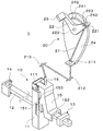
- FIG. 1 shows a vehicle door D equipped with an opening adjustment mechanism according to Embodiment 1 of the present invention.
- the opening adjustment mechanism by Example 1 of this invention is shown. Operation
- movement of the opening degree adjustment apparatus by Example 1 of this invention is shown. Operation
- movement of the opening degree adjustment apparatus by Example 1 of this invention is shown.
- movement of the operating device by Example 1 of this invention is shown.
- movement of the operating device by Example 1 of this invention is shown. It is a figure for demonstrating the structure of the operating device by Example 1 of this invention.
- movement of the operating device by Example 2 of this invention is shown.
- movement of the operating device by Example 2 of this invention is shown.
- FIG. 1 shows a vehicle door D provided with an opening adjustment mechanism 1 according to this embodiment.
- the vehicle door D is rotatably connected to the vehicle body via a hinge H.
- the vehicle door D is provided with an opening adjustment mechanism 1 having a door check mechanism disposed between the door D and the vehicle body.
- the opening adjustment mechanism 1 can limit the opening of the door D according to a user operation.
- the vehicle door D can be provided with other members such as the inner handle 2, a window operation unit (not shown), and an armrest.
- FIG. 2 shows the opening adjustment mechanism 1.
- the opening adjustment mechanism 1 is provided with an opening adjustment device 10 for limiting the opening of the door D and an operation device 20 of the opening adjustment device 10, and the operation device 20 is opened via a connection member 21. It is connected to the degree adjusting device 10.
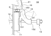
- the opening adjustment device 10 is provided with a door check 11, a check link 12, a check stopper portion 13, a bracket 14, an opening adjustment block 15, and an urging member 16.
- the door check 11 is attached to the door D via a fixing member (not shown) and the check link 12 is arranged to extend inside the door D via the door check 11. . Further, the door check 11 is provided with a rotation shaft 111 of the opening adjustment block 15. The rotation shaft 111 of the opening adjustment block 15 can be fixed to the door D via a member different from the door check 11.
- the check link 12 has one end rotatably attached to the vehicle body via a bracket 14 coupled to the vehicle body.
- the check link 12 extends through the door check 11 and into the door D.
- a check stopper portion 13 is provided at the other end portion of the check link 12 extending inside the door D.
- the check link 12 rotates with respect to the vehicle body as the door D rotates.
- the door D moves in a direction away from or closer to the vehicle body based on the rotation of the door D. Therefore, the check link 12 attached to the vehicle body is rotated based on the rotation of the door D, and when the door D is opened, the check link 12 is pulled out from the inside of the door D that moves away from the vehicle body.
- the check link 12 is inserted into the door D that moves in a direction approaching the vehicle body. Thereby, when the door D rotates, the check link 12 can move in the length direction of the check link 12 relative to the door check 11 attached to the door D.
- the check link 12 is pulled out from the door D as the door D rotates, and moves to one end side of the check link 12 attached to the vehicle body with respect to the door check 11.
- the check stopper portion 13 moves toward the door check 11 by moving the check link 12 toward one end attached to the vehicle body.
- the movement of the check link 12 toward the one end is restricted, and the check link 12 is further restricted from being pulled out from the door D.
- the rotation of the check link 12 is restricted
- the rotation of the door D is also restricted. Therefore, the opening degree of the door D is restricted based on the restriction of the movement of the check link 12.
- the opening degree of the door D when the check stopper portion 13 abuts on the door check 11 is the fully open opening degree of the door D.
- the opening adjustment block 15 includes a first contact portion 151 that contacts the door check 11, a second contact portion 152 that contacts the check stopper portion 13, and a notch 153. It has been.
- the second contact portion 152 is provided to face the first contact portion 151 and have a predetermined distance from the first contact portion 151.
- the cutout portion 153 is provided in the vicinity of the rotation shaft 111 so as to cut out the first contact portion 151 by a predetermined length.
- the opening adjustment block 15 is attached to the door check 11 so as to be rotatable about a rotation shaft 111 provided in the door check 11. Thereby, the opening adjustment block 15 can rotate with respect to the door check 11 and the check link 12.
- the first contact portion 151 provided in the opening adjustment block 15 is configured to check the door when the opening adjustment block 15 rotates so as to go to a position adjacent to the check link 12. 11 abuts.
- the second contact portion 152 is provided so as to face the first contact portion 151 as described above, the check stopper portion 13 provided to contact the door check 11 and Face each other. Therefore, when the door D is opened when the opening adjustment block 15 moves to the position, the check link 12 moves to one end side attached to the vehicle body, and the check stopper portion 13 is moved to the second contact portion 152. Will abut.
- the opening adjustment block 15 is connected to the operation device 20 via an arbitrary connection member 21 including, for example, a wire, a cable, a rod-like member, and the like, and the rotation axis is based on the user operating the operation device 20. Rotate around 111.
- an arbitrary biasing member 16 including, for example, a spring, rubber, or the like applies the opening adjustment block 15 so as to be directed to a position adjacent to the check link 12, that is, a position between the door check 11 and the check stopper portion 13. Rush. Therefore, when the opening adjustment block 15 is disposed at a position between the door check 11 and the check stopper portion 13, the urging member 16 is in a direction in which the first contact portion 151 contacts the door check 11. The opening adjustment block 15 can be energized. As a result, when the opening adjustment block 15 is disposed at the position, the biasing member 16 presses the opening adjustment block 15 against the door check 11, so that the opening adjustment block 15 is rattled due to vibration or the like. Etc. can be prevented.
- the operation device 20 includes a connection member 21 connected to the opening adjustment block 15 of the opening adjustment device 10, a lever 22 (moving member) to which the connection member 21 is connected, a knob 23 operated by a user, a base A stand 24 is provided.
- connection member 21 can be formed of any member including, for example, a wire, a cable, a rod-like member, and the like, and is connected to the opening adjustment block 15 of the opening adjustment device 10 at one end. Further, the connection member 21 is supported by arbitrary connection member support portions 211, 212, 213 and oriented in the extending direction, and is connected to the connection portion 221 of the lever 22 at the other end. In addition, according to arrangement
- connection member support portion can be fixed to the door D or a member coupled to the door D, such as the base 24.
- opening adjustment block 15 and the lever 22 can be directly connected by the connection member 21 without providing the connection member support portions 211, 212, and 213. Since the connecting member 21 is connected to the lever 22 and the opening adjustment block 15, the connection member 21 can move as the lever 22 moves to move the opening adjustment block 15.
- the lever 22 is provided with a connecting portion 221 connected to the connecting member 21, a rotation center point 222, a protruding portion 223, and a knob 23.
- the lever 22 is connected to the base 24 so as to be rotatable about the rotation center point 222, and the rotation center point 222 is fixed to the base 24.
- the protruding portion 223 is provided at a portion facing the base 24 of the lever 22, extends inside the groove portion 241 provided on the base 24, and extends inside the groove portion 241 along the shape of the groove portion 241. Can slide.
- the connecting portion 221 is provided at one end of the lever 22, but the position where the connecting portion 221 is provided is not limited to this, and can be provided at any position of the lever 22 other than the rotation center point 222. .
- the knob 23 is connected to the lever 22, and the user can rotate the lever 22 around the rotation center point 222 by moving the knob 23.
- the knob 23 may be formed integrally with the lever 22 or may be formed as a separate member and connected to the lever 22. In this embodiment, the knob 23 is provided at the end opposite to the end where the connecting portion 221 of the lever 22 is provided. However, the portion of the lever 22 where the knob 23 is provided is not limited thereto.
- the lever 22 can be provided at an arbitrary position.
- the knob may be provided at an end portion where the connection portion 221 is provided, or may be provided at a portion between the connection portion 221 and the rotation center point 222.
- the knob may be provided at the rotation center point 222. In this case, the user can rotate the lever 22 by rotating the knob.
- the base 24 is coupled to the door D via an arbitrary fixing member such as a bolt.
- a groove portion 241 is formed in the base 24.
- the groove 241 is formed along a circle centered on the rotation center point 222 of the lever 22, and the protrusion 223 slides inside the groove 241 when the lever 22 rotates about the rotation center point 222. can do. Further, the end portions 242 and 243 of the groove portion 241 come into contact with the protruding portion 223 of the lever 22 so that the rotation of the lever 22 can be restricted.
- the shape of the groove 241 is not limited to a shape along a circle centered on the rotation center point 222.
- the shape of the groove can be any shape that allows the protrusion to slide inside the groove and that each end of the groove abuts the protrusion 223 of the lever 22 to restrict the rotation of the lever 22. It can be.
- FIGS. 3A and 3B show the operation of the opening adjustment device 10.
- 3A shows the opening adjustment device 10 when the opening degree of the door D is set to the fully open opening degree
- FIG. 3B shows the movement of the opening adjustment device 10 when the opening degree of the door D is limited.
- the opening degree adjustment block 15, the urging member 16, and the connecting member 21 shown in FIG. 3A are indicated by a two-dot chain line.
- the bracket 14 and the operating device 20 are omitted for simplification of description.
- the opening degree of the door D When the opening degree of the door D is set so that the user can rotate the door D to the full opening degree without restricting the opening degree of the door D, as shown in FIG.
- the opening adjustment block 15 is rotated upward with respect to the check link 12 about the rotation shaft 111.
- the first contact portion 151 does not contact the door check 11
- the second contact portion 152 does not contact the check stopper portion 13.
- the check stopper portion 13 is attached to the vehicle body of the check link 12 without contacting the opening adjustment block 15 when the check link 12 moves in accordance with the opening operation of the door D. To contact the door check 11. Therefore, the door D can be rotated to the fully open position.
- the opening adjustment block 15 follows the movement of the connecting member 21 based on the operation of the operation device 20 as shown in FIG. It rotates in the direction (downward) indicated by the arrow A1 from the position of the opening adjustment block 15 in FIG.
- the opening adjustment block 15 rotates along the arrow A ⁇ b> 1 in a direction toward the position between the door check 11 and the check stopper portion 13 in a direction toward the position between the door check 11 and the check stopper portion 13, the first contact portion 151 contacts the door check 11.
- the opening adjustment block 15 rotates to a position where the first contact portion 151 contacts the door check 11
- the opening adjustment block 15 moves between the door check 11 and the check stopper portion 13.
- the second contact portion 152 that faces the first contact portion 151 faces the check stopper portion 13 that faces the door check 11.
- the opening adjustment block 15 includes a first contact portion 151 having a predetermined length in the longitudinal direction of the check link 12 in the vicinity of the rotation shaft 111 of the opening adjustment block 15.
- a cutout portion 153 is provided so as to cut out only. For this reason, the load when the opening adjustment block 15 rotates to the position between the door check 11 and the check stopper portion 13 and the first contact portion 151 contacts the door check 11 is applied to the rotation shaft 111. It is possible to avoid concentrating on the portion of the first contact portion 151 in the vicinity.
- the check link 12 moves to one end side attached to the vehicle body, and the check link 12 moves along with the check link 12.
- the stopper part 13 moves.
- the opening adjustment block 15 is arranged so that the second contact portion 152 faces the check stopper portion 13 as described above, the check stopper portion 13 is moved based on the movement of the check stopper portion 13. It contacts the second contact portion 152. Since the opening adjustment block 15 is in contact with the door check 11 at the first contact portion 151, movement of the check link 12 toward one end attached to the vehicle body is limited.
- the opening adjustment block 15 is sandwiched between the door check 11 and the check stopper portion 13, and the opening adjustment block 15 moves to the check stopper portion 13, that is, toward one end of the check link 12 attached to the vehicle body.
- the movement of the check stopper 13 and the check link 12 is restricted.
- the movement of the check link 12 is restricted, and the rotation of the door D in the opening direction is restricted. Therefore, the opening degree of the door D can be limited by rotating the opening degree adjusting block 15 and disposing it between the door check 11 and the check stopper portion 13.
- the opening adjusting device 10 includes the door check 11 attached to the vehicle door D, and one end portion rotatably attached to the vehicle body and extending inside the vehicle door D.
- a check link 12 and a check stopper portion 13 provided at the other end of the check link 12 extending inside the vehicle door D are provided.
- the check link 12 can move in the longitudinal direction of the check link 12 relative to the door check 11 based on the rotation of the door D.
- the opening adjustment device 10 further includes an opening adjustment block 15 that rotates with respect to the check link 12.
- the opening adjustment block 15 has a first contact portion 151 that contacts the door check 11, a first contact portion 151 that faces the first contact portion 151, and has a predetermined distance from the first contact portion 151.
- a second contact portion 152 that contacts the stopper portion 13 is included.
- the opening adjustment block 15 rotates toward the check link 12 and the first contact portion 151 comes into contact with the door check 11, the opening adjustment block 15 is attached to the vehicle body of the check link 12. It is restricted to move to.
- the opening adjustment block 15 moves to one end of the check link 12. The movement of the check link 12 to the department side is restricted.
- the movement of the check link 12 toward the one end portion attached to the vehicle body of the check link 12 is limited by the opening adjustment block 15, so that an external force in the opening operation direction is unintentionally applied to the door D Even if it is a case, it can prevent that the door D opens.
- the restriction on the opening degree of the door D restricts only the door D from rotating in the opening direction from the restricted opening degree. Therefore, the door D is in the range from the opening degree to the fully closed position. It can rotate freely.
- the opening adjustment block 15 moves between the door check 11 and the check stopper portion 13 by rotating, the positional adjustment of the opening adjustment block 15 with respect to the door check 11 or the check stopper portion 13 or the like. Can be prevented.
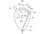
- FIG. 4A and 4B show the operation of the controller device 20.
- 4A shows the operating device 20 when the opening degree of the door D is set to the fully open opening degree
- FIG. 4B shows the operating device 20 when the opening degree of the door D is limited.
- the lever 22 is connected to the opening adjustment block 15 via the connecting member 21. Therefore, the connecting member 21 applies tension to the lever 22 based on the load of the opening adjustment block 15 and the biasing member 16 biasing the opening adjustment block 15. Therefore, the connecting member 21 always applies tension to the connecting portion 221 of the lever 22 in the direction (opening adjustment block 15 side) in which the opening adjusting block 15 in the extending direction of the connecting member 21 is connected.
- the lever 22 is connected to the base 24 so as to be rotatable at the rotation center point 222, so that the connection member 21 moves toward the opening adjustment block 15 according to the position of the connection portion 221. It can rotate based on tension.
- the lever 22 When the opening degree of the door D is set so that the user can rotate the door D to the full opening degree without restricting the opening degree of the door D, the lever 22 has the protruding portion 223. It is located at the first position P1 in contact with the first end 242 of the groove 241. At the first position P1, the protrusion 223 of the lever 22 abuts on the first end 242 of the groove 241 provided on the base 24, so the first end 242 is the opening adjustment block of the connecting member 21.
- the rotation of the lever 22 based on the tension toward the 15 side is limited. That is, the first end 242 of the groove 241 contacts the lever 22 when the lever 22 is in the first position P1, and restricts the lever 22 from being moved by the tension applied from the connecting member 21.
- the connecting member 21 applies tension to the lever 22 toward the opening adjustment block 15 of the connecting member 21, so that the connecting portion 221 moves to the opening adjustment block 15 side of the connecting member 21.
- the lever 22 is urged to do so. Therefore, the lever 22 can be held at the first position P ⁇ b> 1 by the tension of the connecting member 21 applied from the connecting member 21 toward the opening adjustment block 15 and the first end 242 of the groove 241.
- the lever 22 rotates around the rotation center point 222 as the knob 23 moves.
- the protruding portion 223 of the lever 22 slides in the direction from the first end portion 242 toward the second end portion 243 along the shape of the groove portion 241.
- the lever 22 moves to the second position P2 where the protruding portion 223 contacts the second end 243 of the groove 241 as shown in FIG. 4B.
- the projecting portion 223 contacts the second end 243 of the groove 241 provided on the base 24, so the second end 243 moves toward the opening adjustment block 15 side of the connecting member 21.
- the rotation of the lever 22 based on the tension is limited. That is, the second end 243 of the groove 241 contacts the lever 22 when the lever 22 is in the second position P2, and restricts the lever 22 from moving due to the tension applied from the connecting member 21. It functions as a second stopper portion.
- the connecting member 21 applies tension to the lever 22 toward the opening adjustment block 15 of the connecting member 21, so that the connecting portion 221 moves to the opening adjustment block 15 side of the connecting member 21.
- the lever 22 is urged to do so. Therefore, the lever 22 can be held at the second position P ⁇ b> 2 by the tension of the connecting member 21 applied from the connecting member 21 toward the opening adjustment block 15 and the second end 243 of the groove 241.
- the rotation center point 222 is on the right side (one side) of the connection member 21 in the drawing. Therefore, when the lever 22 is in the first position P1, the connecting member 21 urges the lever 22 to rotate leftward on the paper surface based on the tension toward the opening adjustment block 15, and the first portion of the groove portion 241 is urged. The end 242 of this restricts the rotation.
- the rotation center point 222 is on the left side (opposite side) with respect to the connection member 21.
- the connecting member 21 urges the lever 22 to rotate rightward on the paper surface based on the tension toward the opening adjustment block 15, and the second portion of the groove portion 241 is urged.
- the end 243 of this restricts the rotation. Therefore, the lever 22 is urged to rotate in the opposite directions at the first position P1 and the second position P2, and the reverse direction is provided by the first and second ends 242 and 243 of the groove portion 241. Each rotation is limited.
- the lever 22 can be held at different positions, that is, the first position P1 and the second position P2.
- the opening adjustment block 15 is connected to the lever 22 via the connection member 21. Therefore, since the operating device 20 can hold the lever 22 at two different positions, the opening adjustment block 15 connected to the lever 22 can be held at two different operating positions.
- the opening adjustment block 15 that restricts the opening of the door D moves the connection member 21 relative to the opening adjustment block 15, for example, raises or lowers the opening adjustment block 15. It rotates according to the movement in the direction. Therefore, the opening adjustment device 10 operates in accordance with the movement of the connection portion 221 of the lever 22 relative to the opening adjustment block 15 in the operating device 20 connected to the connection member 21.
- the opening adjustment device 10 between the first position P1 and the second position P2 of the lever 22, by ensuring the moving stroke of the connecting portion 221 of the lever 22 to which the connecting member 21 is connected with respect to the opening adjustment block 15.
- the operation of the opening adjustment device 10 according to the positions P1, P2 of the lever 22 can be realized. That is, the opening degree of the door D can be limited and released by the opening degree adjusting device 10 associated with the operation of moving the lever 22 of the operating device 20.
- the movement stroke of the connecting portion 221 relative to the opening adjustment block 15 is between the first position P1 and the second position P2 in the direction away from the opening adjustment block 15 or approaching the opening adjustment block 15.
- the connection member support portion 211 closest to the connection portion 221 and the rotation center point 222 are Corresponds to the extending direction of the passing line.
- the direction corresponds to the extending direction of a line passing through the portion of the opening adjustment block 15 to which the connecting member 21 is connected and the rotation center point 222.
- the connecting portion 221 at the first and second positions P1, P2 is Need only be in different positions.
- the first position P1 and the second position are set such that the distance between the rotation center point 222 and the connection member 21 when the lever 22 is at the first and second positions P1 and P2 is different.
- the position P2 is set. That is, the distance L1 from the rotation center point 222 to the connection member 21 at the first position P1 shown in FIG. 4A is larger than the distance L2 from the rotation center point 222 to the connection member 21 at the second position P2 shown in FIG. 4B.
- the first and second positions P1 and P2 are set to be shorter.
- the position of the connection portion 221 and the connection member support portion 211 decreases as the distance from the rotation center point 222 to the connection member 21 decreases in the rotation range of the lever 22. It approaches the extension line of the line passing through the rotation center point 222. Therefore, the shorter the distance from the rotation center point 222 to the connection member 21 in the rotation range of the lever 22, the longer the distance from the connection member support part 211 to the connection part 221, and the connection part 221 moves away from the opening adjustment block 15. Will move in the direction. Accordingly, by setting the first position P1 and the second position P2 such that the distance L1 at the first position P1 is shorter than the distance L2 at the second position P2, the opening degree adjustment block of the connecting portion 221 is set. 15 can be secured.
- connection portion 221 Even when the connection member support portion is not used, the position of the connection portion 221 is changed to the position of the connection member 21 of the opening adjustment block 15 as the distance from the rotation center point 222 to the connection member 21 becomes shorter in the rotation range of the lever 22. It approaches an extension of a line passing through the connected part and the rotation center point 222. Therefore, in this case as well, the connection portion 221 moves away from the opening adjustment block 15 as the distance from the rotation center point 222 to the connection member 21 becomes shorter in the rotation range of the lever 22. Accordingly, by setting the first position P1 and the second position P2 such that the distance L1 at the first position P1 is shorter than the distance L2 at the second position P2, the opening degree adjustment block of the connecting portion 221 is set. 15 can be secured.
- the connecting portion 221 at the first position P1 is connected to the connecting portion 221 at the second position P2.
- the opening adjustment block 15 is rotated upward to set the opening degree of the door D to the fully open opening degree, and the lever 22 is set to the second position P2.
- the opening adjustment block 15 can be set to rotate downward and to limit the opening of the door D.
- the lever 22 of the controller device 20 is moved by setting the first position P1 and the second position P2 such that the distance L1 at the first position P1 is shorter than the distance L2 at the second position P2. Operation
- movement of the opening degree adjusting apparatus 10 matched with operation is realizable.
- the operating device 20 includes the connecting member 21 configured to be connected to the opening adjusting device 10 that adjusts the opening of the vehicle door D, and the other end of the connecting member 21.
- the lever 22 (moving member) connected to the is provided.
- the lever 22 has a rotation center point 222, which is a center point around which the lever 22 rotates, and moves between the first position P1 and the second position P2 with rotation about the rotation center point 222.
- the operating device 20 includes a base 24 on which a groove portion 241 is formed, and the groove portion 241 includes a first end portion 242 (first stopper portion) and a second end portion 243 (second stopper portion). .
- the first end 242 of the groove 241 contacts the lever 22 when the lever 22 is in the first position P1, and restricts the lever 22 from being moved by the tension applied from the connecting member 21.
- the second end 243 of the groove 241 contacts the lever 22 when the lever 22 is in the second position P2, and restricts the lever 22 from moving due to the tension applied from the connecting member 21.
- the rotation center point 222 is on one side with respect to the connecting member 21 when the lever 22 is at the first position P1, and when the lever 22 is at the second position P2, the lever 22 is at the first position P1. Compared to the case of the connection member 21, the connection member 21 is on the opposite side.
- the operating device 20 is configured such that the lever 22 is moved to the first and second positions P1 and P1 by the tension applied by the connecting member 21 and the first and second ends 242 and 243 of the groove 241. It can be held at P2. Therefore, the operating device 20 can hold different operating states of the opening adjusting device 10 connected to the lever 22 with a simple configuration.
- the connecting member 21 applies a tension to the lever 22 toward the opening adjustment device 10 side.
- the lever 22 if the lever 22 moves beyond the position where the connecting member 21 and the rotation center point 222 overlap, the lever 22 automatically moves to the first position P1 or the destination position based on the tension. Rotate to the second position P2. Therefore, the operating device 20 according to the present embodiment can reduce the operating stroke of the lever 22 to be operated by the user, and can improve the operability of the operating device of the opening adjustment device.
- the distance from the rotation center point 222 when the lever 22 is at the first position P1 to the connection member 21 is the rotation center when the lever 22 is at the second position P2.
- the first and second positions P1, P2 are set so as to be shorter than the distance from the point 222 to the connection member 21. Therefore, the movement stroke of the connection part 221 with respect to the opening degree adjustment block 15 of the opening degree adjusting device 10 that restricts the opening degree of the door D can be ensured between the first position P1 and the second position P2. .
- the movement stroke of the opening degree adjustment block 15 according to the movement stroke of the connection part 221 with respect to the opening degree adjustment block 15 is securable. Therefore, the operation of moving the lever 22 of the operating device 20, that is, the opening degree of the door D is restricted and released by the opening degree adjustment block 15 associated with the first and second positions P1, P2 of the lever 22, respectively. Can be realized.
- the opening of the door D is limited by using the opening adjustment block 15 that rotates, but the movement of the opening adjustment block 15 is not limited to rotation.
- the opening adjustment block may be configured to slide between the door check 11 and the check stopper portion 13 as the connection member 21 moves.
- the door D or the opening adjustment block housing is provided with a guide portion that engages with the opening adjustment block to guide the sliding of the opening adjustment block so that the door can be checked accurately. 11 and the check stopper portion 13 can be slid.
- the rotation direction or sliding direction of the opening adjustment block is not limited to the vertical direction.
- the opening adjustment block In order for the opening adjustment block to operate so as to limit the opening of the door D, it is only necessary that the opening adjustment block can be moved to a position between the door check 11 and the check stopper portion 13. Therefore, the opening adjustment block can move in any direction so that the opening adjustment block moves to a position between the door check 11 and the check stopper portion 13 and a position not sandwiched between the door check 11 and the check stopper portion 13. It can be configured to rotate or slide. Therefore, the position of the opening adjustment block with respect to the check link 12 can also be set arbitrarily. For example, the opening adjustment block can be arranged below or on the side of the check link 12.
- the opening adjustment device 10 including the opening adjustment block 15 that restricts the opening of the door D is used.
- the configuration of the opening adjustment device 10 is limited to this. Absent.
- the operating device 20 according to the present embodiment can be applied to any opening degree adjusting device in which a member for limiting the opening degree of the door D moves according to the movement of the connecting member 21. Therefore, for example, in the door check mechanism described in Patent Document 1, the restricting member of the tightening mechanism is configured to move in accordance with the movement of the connecting member 21 of the operating device 20 according to the present embodiment, so that the operating device 20 is connected to the door. It can also be applied to a check mechanism.
- the lever 22 has a substantially L shape, but the shape of the lever 22 is not limited to this.
- the lever 22 may be formed in an arbitrary shape such as a substantially linear shape, a wavy shape, a U shape, and a V shape.
- the first stopper portion and the second stopper portion in the present embodiment are configured by the respective end portions 242 and 243 of the groove portion 241 provided in the base 24 that abuts the protruding portion 223 of the lever 22.
- the configuration of the stopper portion is not limited to this.
- each stopper portion abuts on the lever 22 when the lever 22 is in each of the first position P1 and the second position P2, and restricts the movement of the lever 22 based on the tension applied from the connecting member 21.
- Any member can be used. Therefore, each stopper part may be arbitrary protrusion members, such as a block provided in the door D or the base 24, and contacting the lever 22, for example.
- the rotation center point 222 of the lever 22 according to the present embodiment is connected to the base 24 above the connection member support portion 211, but the position to be connected to the base 24 is not limited to this, and an arbitrary position of the base 24 Can be connected to the location. Further, the rotation center point 222 may be directly connected to the door D without passing through the base 24.
- the rotation center point 222 is on the right side of the drawing with respect to the connecting member 21, and when the lever 22 is at the second position P2, the rotation center point 222 is The first position P1 and the second position P2 are set so as to be on the left side of the drawing with respect to the connection member 21.
- the setting of the first position P1 and the second position P2 is not limited to this.
- the second position is such that the rotation center point 222 is on the side opposite to the connection member 21 compared to when the lever 22 is in the first position. What is necessary is just to be comprised.
- the rotation center point 222 is on the left side of the drawing with respect to the connection member 21, and when the lever 22 is in the second position, the rotation center point 222 is with respect to the connection member 21.
- the first position and the second position may be set so as to be on the right side of the drawing.
- the first position and the second position are set at arbitrary positions according to the position of the connection member support portion closest to the connection portion 221 and the position of the rotation center point 222. Can be set.
- the first position and the second position are arbitrary depending on the part to which the connection member 21 of the opening adjustment block 15 is connected and the position of the rotation center point 222.
- the first position is such that the rotation center point 222 is on the upper side or the lower side of the connection member 21 at each position.
- the position and the second position may be set. That is, when the lever 22 is in the first position, the rotation center point 222 is on the upper side of the drawing with respect to the connection member 21, and when the lever 22 is in the second position, the rotation center point 222 is on the connection member 21.
- the first position and the second position may be set so as to be on the lower side of the drawing.
- FIG. 5 is a diagram for explaining the configuration of the controller device 20.
- a virtual line VL passing through the lever 22, the connection member support portion 211, and the rotation center point 222 when in the first position P ⁇ b> 1 is indicated by a two-dot chain line.
- the first rotation center point 222 is in the opposite direction with respect to the connection member 21.
- the position P1 and the second position P2 are set.
- the connection part 221P1 at the first position P1 and the connection part 221P2 at the second position P2 are on opposite sides with respect to the virtual line VL passing through the connection member support part 211 and the rotation center point 222.
- First and second positions P1, P2 are set. In this way, by setting the first and second positions P1 and P2, the lever 22 is rotated in the opposite direction by the tension applied from the connecting member 21 at the first and second positions P1 and P2. Will be energized.
- the rotation of the lever 22 at the first and second positions P1 and P2 is limited by the first and second ends 242 and 243 of the groove 241 respectively. Therefore, the lever 22 is moved to the first and second positions P ⁇ b> 1 by the tension of the connecting member 21 applied from the connecting member 21 toward the opening adjustment block 15 and the first and second ends 242 and 243 of the groove 241. , P2.
- the first and second virtual lines passing through the rotation center point 222 and the position before and after the operation of the portion to which the connection member 21 of the opening adjustment block 15 is connected are connected.
- the first position and the second position are set so that the connecting portion 221 in the second position is on the opposite side to either line. Thereby, there can exist an effect similar to the case where the said rotation support member is used.
- the first and second positions P1 and P2 may be set as follows.
- the rotation center point 222 connects the connection part 221P1 at the first position P1 from the connection member support part 211, the line S2 connecting the connection part 221P2 at the second position P2 from the connection member support part 211, and the connection part.
- the first and second positions P1 and P2 may be set so as to be inside an area AR surrounded by a line segment S3 connecting 221P1 and 221P2. Even in such a case, the lever 22 is urged to rotate in the opposite direction by the tension applied from the connecting member 21 at the first and second positions P1, P2.
- the lever 22 is moved to the first and second positions P ⁇ b> 1 by the tension applied to the opening adjustment block 15 of the connecting member 21 and the first and second ends 242 and 243 of the groove 241. , P2.
- the line segment S1 or S2 is on a virtual line VL passing through the connection member support portion 211 and the rotation center point 222, the bias of rotation of the lever 22 caused by the tension applied by the connection member 21 is balanced. Therefore, since the lever 22 is rotated by slight vibration or the like, the lever 22 cannot be held.
- the connecting portions 221P1, 221P2 at the first and second positions P1, P2 are The first and second positions P1, P2 are set so as not to be positioned on the virtual line VL.
- the position of the rotation center point 222 it is 1st and 2nd. By setting the position, the same effect can be obtained.
- the rotation center point 222 is fixed.
- the configuration of the operating device according to the present invention is not limited to this, and the operating device can also be configured so that the rotation center point of the lever moves as the lever moves.
- an operation device in the case where the rotation center point of the lever moves as the lever moves will be described with reference to FIGS. 6A and 6B.
- the structure of the opening degree adjustment apparatus is the same as that of the opening degree adjustment apparatus 10 by Example 1, the same referential mark is attached
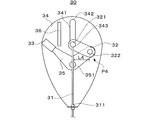
- FIG. 6A and 6B show the operation of the operating device 30 according to the present embodiment.
- FIG. 6A shows the operating device 30 when the opening degree of the door D is set to the fully opened opening degree
- FIG. 6B shows the operating device 30 when the opening degree of the door D is limited.
- the operating device 30 includes a connection member 31, a first lever 32, a knob 33, a base 34, a second lever 35, and a protruding member 36.
- connection member 31 is connected to the opening adjustment block 15 of the opening adjustment device 10 at one end, supported by the connection member support portion 311 and oriented in the extending direction. Further, the connecting member 31 is connected to the connecting portion 321 of the first lever 32 at the other end, and a tension is applied to the connecting portion 321 toward the opening adjustment block 15 side of the connecting member 31.
- the first lever 32 is provided with a connection portion 321 connected to the connection member 31 and a first rotation center point 322 that is the center of rotation of the first lever 32.
- the connecting portion 321 extends in the direction of the base 34 and can slide inside the groove 341 along the shape of the groove 341 provided on the base 34.
- the first rotation center point 322 is not fixed to the base 34 and can move with the movement of the first lever 32.
- the first lever 32 is rotatably connected to the second lever 35 at the first rotation center point 322.
- the base 34 is coupled to the door D using an arbitrary fixing member such as a bolt.
- the base 34 is provided with a groove portion 341, and the groove portion 341 includes end portions 342 and 343.
- the second lever 35 is rotatably connected to the first lever 32 at the first rotation center point 322 and is rotatably connected to the base 34 at the second rotation center point 351.
- the second lever 35 is provided with a knob 33 operated by the user.
- the second rotation center point 351 is fixed to the base 34.
- the second lever 35 rotates around the second rotation center point 351, and the first rotation center point 322 can move according to the rotation of the second lever 35.
- the 2nd rotation center point 351 is being fixed to the base 34, you may be fixing to the door D not via the base 34.
- the protruding member 36 is provided on the base 34 at a position where the first lever 32 contacts the first lever 32 when the first lever 32 is at the first position P3 shown in FIG. 6A.
- the connecting portion 321 of the first lever 32 can move along the groove portion 341 of the base 34. Further, the first rotation center point 322 of the first lever 32 can move according to the rotation of the second lever 35. Therefore, the first rotation center point 322 of the first lever 32 moves according to the rotation direction of the second lever 35 when the connection portion 321 moves along the shape of the groove portion 341.
- the first lever 32 is the first lever 32. It moves while rotating around the rotation center point 322.
- the first lever 32 is connected to the opening adjustment block 15 via the connection member 31, so that the connection member 31 can be opened according to the position of the connection portion 321. It can move based on the tension to the degree adjustment block 15 side.
- the first lever 32 When the opening degree of the door D is set so that the user can rotate the door D to the full opening degree without restricting the opening degree of the door D, the first lever 32 is As shown to 6A, it is located in the 1st position P3 which contact
- connection member 31 applies tension to the first lever 32 toward the opening adjustment block 15 of the connection member 31, so that the connection portion 321 opens the opening adjustment block 15 of the connection member 31.
- the first lever 32 is biased so as to move to the side. Therefore, the first lever 32 can be held at the first position P3 by the tension of the connecting member 31 applied from the connecting member 31 toward the opening adjustment block 15 and the protruding member 36.
- the second lever 35 moves the second rotation center point 351 as the knob 33 moves. It rotates in the direction shown by arrow A4 in FIG. 6A as the center.
- the first lever 32 connected to the second lever 35 at the first rotation center point 322 follows the rotation of the second lever 35 and the first lever It moves while rotating around the rotation center point 322.
- the connecting portion 321 of the first lever 32 slides along the shape of the groove portion 341 in the direction toward the second end portion 343 along the arrow A5 in FIG. 6A.
- the first lever 32 and the second lever 35 move to the second position P4 where the connecting portion 321 contacts the second end 343 of the groove 341 as shown in FIG. 6B.
- the connection portion 321 contacts the second end portion 343 of the groove portion 341 provided on the base 34, so the second end portion 343 moves toward the opening adjustment block 15 side of the connection member 31.
- the movement of the first lever 32 based on the tension is limited. That is, the second end portion 343 of the groove portion 341 contacts the first lever 32 when the first lever 32 is at the second position P4, and the first lever 32 is applied from the connection member 31. It functions as a second stopper portion that restricts movement due to tension.
- connection member 31 applies tension to the first lever 32 toward the opening adjustment block 15 of the connection member 31, so that the connection portion 321 moves toward the opening adjustment block 15.
- the first lever 32 is biased. Therefore, the first lever 32 can be held at the second position P4 by the tension of the connection member 31 applied from the connection member 31 toward the opening adjustment block 15 and the second end 343 of the groove 341. it can.
- the second lever 35 is moved to the second position. It rotates in the direction opposite to the direction shown by the arrow A4 around the rotation center point 351.
- the first lever 32 connected to the second lever 35 at the first rotation center point 322 rotates the second lever 35. Accordingly, it moves while rotating around the first rotation center point 322.
- connection portion 321 of the first lever 32 follows the shape of the groove portion 341 in a direction toward the first end portion 342 of the groove portion 341 along the direction opposite to the direction indicated by the arrow A5 in FIG. 6A. Slide. Thereafter, the first lever 32 moves to the first position P3 in contact with the protruding member 36 as the second lever 35 moves.
- the first rotation center point 322 is on the left side (one side) of the connection member 31. Therefore, when the first lever 32 is in the first position P3, the connecting member 31 urges the first lever 32 to rotate rightward on the paper surface based on the tension toward the opening adjustment block 15 side.
- the projecting member 36 limits the rotation.
- the first rotation center point 322 is on the right side (opposite side) with respect to the connection member 31. Therefore, when the first lever 32 is at the second position P4, the connecting member 31 urges the first lever 32 to rotate leftward on the paper surface based on the tension toward the opening adjustment block 15 side.
- the second end 343 of the groove 341 limits the rotation. Accordingly, the first lever 32 is urged to rotate in the opposite directions at the first position P3 and the second position P4, and is reversed by the protruding member 36 and the groove portion 341 and the second end portion 343. Each rotation in direction is limited.
- the first lever 32 can be held at different positions, that is, the first position P3 and the second position P4.
- the opening adjustment block 15 is connected to the first lever 32 via the connection member 31. Therefore, since the operating device 30 can hold the first lever 32 at two different positions, the opening adjustment block 15 connected to the first lever 32 can be held at two different operating positions. it can.
- the moving stroke of the adjustment block 15 can be ensured. Therefore, the operation of the opening adjustment device 10 according to the movement of the connection member 31, that is, the operation of the opening adjustment device 10 associated with the operation of moving the first lever 32 of the operation device 30 can be realized. it can.
- the distance L3 from the first rotation center point 322 to the connecting member 31 at the first position P3 is the second position P4.
- the first and second positions P3 and P4 are set so as to be shorter than the distance L4 from the first rotation center point 322 to the connection member 31.
- the opening adjustment block 15 of the connection portion 321 in the first lever 32 is changed.
- the principle of securing the movement stroke with respect to is substantially the same as the principle in the operating device 20 according to the first embodiment.
- the first lever 32 is moved by the second lever 35. Therefore, in the operating device 30 according to the present embodiment, the movement of the first lever 32 by the second lever 35 can be taken into account in order to ensure the movement stroke of the connection portion 321 relative to the opening adjustment block 15.
- the second lever 35 is connected to the first lever 32 so as to shorten the distance.
- the movement stroke of the connecting portion 321 relative to the opening adjustment block 15 according to the rotational position of the first lever 32 causes the second lever 35 to move away from the opening adjustment block 15 of the first lever 32.
- a moving stroke can be added. Therefore, with this configuration, it is possible to secure a longer movement stroke of the connecting portion 321 with respect to the opening adjustment block 15.
- the first lever 32 is not directly operated by the user, so the first lever 32 has a first lever 32 in order to ensure a moving stroke away from the opening adjustment block 15.
- a groove portion 341 is used as a guide portion for guiding the movement of 32.
- the first rotation center point 322 is in the opposite direction with respect to the connection member 31 at the first position P3 and the second position P4.
- Each position P3, P4 is set. Therefore, the operating device 30 holds the first lever 32 at the first and second positions P3 and P4 by the tension applied by the connecting member 31, the protruding member 36, and the groove 341 and the second end 343. Can do. Therefore, even when the rotation center point 322 of the first lever 32 moves along with the movement of the first lever 32, the operating device 30 is provided with the opening adjustment device 10 connected to the first lever 32.
- the different operation states can be held with a simple configuration.
- the connecting member 31 applies a tension toward the opening adjusting device 10 to the first lever 32. Therefore, when the user rotates the second lever 35 and moves the first lever 32, if the first lever 32 moves beyond the position where the first rotation center point 322 and the connection member 31 overlap, The first lever 32 automatically rotates to the first position P3 or the second position P4 of the movement destination based on the tension. Therefore, the operating device 30 according to the present embodiment can reduce the operating stroke of the second lever 35 to be operated by the user, and can improve the operability of the operating device of the opening adjustment device.
- the second lever 35 has a substantially L shape, but the shape of the second lever 35 is not limited thereto.
- the second lever 35 may be formed in an arbitrary shape such as a substantially linear shape, a wavy shape, a U shape, and a V shape.
- the shape of the first lever 32 can also be an arbitrary shape.
- the first stopper portion is configured by a protruding member 36 that abuts on the first lever 32, and the second stopper portion is on the base 34 that abuts on the connection portion 321 of the first lever 32. This is constituted by the second end portion 343 of the groove portion 341 provided.
- the configuration of the stopper portion is not limited to this.
- Each stopper portion abuts on the first lever 32 when the first lever 32 is in each of the first position P3 and the second position P4, and is based on the tension applied from the connecting member 31.
- Any member that can limit the movement of the first lever 32 may be used. Therefore, each stopper portion may be, for example, a protruding member such as a block that is provided on the door D or the base 34 and contacts the first lever 32, or a groove portion.
- the first lever 32 is not directly operated by the user, so that the connecting portion 321 slides inside the connecting portion 321 as a guide portion that guides the movement of the first lever 32.
- the guide portion is not limited to the movement of the first lever 32.
- it may be a protruding member that contacts the first lever 32 during the movement of the first lever 32 and guides the movement of the first lever 32.
- the extending direction of the guide portion that guides the movement of the first lever 32 is not limited to the vertical direction, and can be set in any direction.
- the user can move the first lever 32 to the first position P3 and the second position P4 only by moving the second lever 35.
- the configuration for moving the first lever 32 to the first position P3 and the second position P4 is not limited to this.
- the first lever 32 is moved to the first position P3 and the second position P4 by moving the second lever 35 and moving the first lever 32 in the extending direction of the groove 341.
- Opening adjustment mechanism 2: Inner handle, 10: Opening adjustment device, 11: Door check, 12: Check link, 13: Check stopper, 14: Bracket, 15: Opening adjustment block, 16: Energizing Members, 20, 30: operation device, 21, 31: connection member, 22, 32, 35: lever (moving member), 23, 33: knob, 24, 34: base, 36: protruding member (stopper), 111: Rotating shaft 151, 152: Contact part 153: Notch part 211, 212, 213, 311: Connection member support part 221, 321: Connection part 222, 322, 351 1: Center of rotation 241 , 341: groove portion, 242, 243, 342, 343: end portion (stopper portion) of groove portion, D: door for vehicle, H: hinge, P1, P3: first position, P2, P4: second position, VL: Virtual line
Landscapes
- Engineering & Computer Science (AREA)
- Mechanical Engineering (AREA)
- Lock And Its Accessories (AREA)
- Hinges (AREA)
Abstract
車両用ドアの開度を調整する開度調整装置に接続されるように構成される接続部材と、接続部材に接続されるとともに、回転中心点を有し、回転中心点を中心とした回転にともなって第1の位置及び第2の位置の間で移動する、移動部材と、移動部材が第1の位置において接続部材の張力によって移動することを制限する第1のストッパ部と、移動部材が第2の位置において接続部材の張力によって移動することを制限する第2のストッパ部とを備え、第1の位置では、回転中心点は接続部材に対して一方の側にあり、第2の位置では、回転中心点は接続部材に対して反対の側にある、開度調整装置の操作装置。
Description
本発明は、車両用ドアの開度調整装置の操作装置に関する。
一般的な車両用ドアは一方の側部においてドアヒンジを介して車体に回転可能に接続され、同側部と車体との間に設けられたドアチェック機構によって、全開開度や半開開度などに所定の開度(開動作位置)に保持されることができる。
しかしながら、従来のドアチェック機構によるドア開度の保持、特に半開開度の保持は、当該開度よりもドアが開くことを防止するものではない。そのため、半開開度に保持されたドアに対して使用者の意図に反して開方向の力が印加された場合であっても、従来のドアチェック機構ではドアが開動作することを防止できず、ドアが車両の側方にある障害物等にぶつかってしまう場合があった。
そのため、設定されたドアの開度以上にドアが開くことを制限することができる、ドアの開度調整装置が提案されている。例えば、特許文献1には、ドアチェック機構のチェックリンクを挟持する挟持片を有する締付け機構によって、チェックリンクに移動拘束力を付加してチェックリンクの移動を防止し、ドアの開度を固定するドアチェック機構が提案されている。特許文献1において提案されているドアチェック機構は、締付け機構のアクチュエータとなるソレノイドに電流を印加することで、締付け機構の動作を電気的に制御するように構成されている。
ドアの開度調整装置では、誤操作防止の観点から、ドアの開度設定、すなわち開度調整装置の動作状態がユーザの意図に反して容易に切り替わらないように、操作された動作状態が保持されることが望まれる。これに関し、特許文献1に示されるドアの開度を固定するドアチェック機構では、締付け機構によるチェックリンクの締付け状態及び締付け解除状態の保持及び切換えを電気的に制御する。そのため、特許文献1に示されるドアチェック機構では、操作部の構成が複雑になる。
そこで、本発明では、車両用ドアの開度を制限するための開度調整装置の動作状態を簡易な構成で保持することができる、開度調整装置の操作装置を提案する。
本発明の一実施態様に係る開度調整装置の操作装置は、車両用ドアの開度を調整する開度調整装置に接続されるように構成される接続部材と、前記接続部材に接続される移動部材であって、該移動部材が回転する中心点である回転中心点を有し、前記回転中心点を中心とした回転にともなって第1の位置及び第2の位置の間で移動する、移動部材と、前記移動部材が第1の位置にあるときに、前記移動部材と当接し、前記移動部材が前記接続部材から印加される張力によって移動することを制限する第1のストッパ部と、前記移動部材が第2の位置にあるときに、前記移動部材と当接し、前記移動部材が前記接続部材から印加される張力によって移動することを制限する第2のストッパ部とを備え、前記移動部材が前記第1の位置にあるときには、前記回転中心点は前記接続部材に対して一方の側にあり、前記移動部材が前記第2の位置にあるときには、前記移動部材が前記第1の位置にあるときと比べて、前記回転中心点は前記接続部材に対して反対の側にある。
本発明による、開度調整装置の操作装置は、接続部材から印加される張力とストッパ部との作用により、移動部材を第1の位置及び第2の位置のそれぞれの位置において保持することができる。そのため、当該操作装置は、移動部材に接続された開度調整装置の異なる動作状態を簡易な構成で保持することができる。
本発明のさらなる特徴は、添付図面を参照して例示的に示した以下の実施例の説明から明らかになる。
以下、本発明を実施するための例示的な実施例を、図面を参照して詳細に説明する。ただし、以下の実施例で説明する寸法、材料、形状、構成要素の相対的な位置等は任意であり、本発明が適用される装置の構成又は様々な条件に応じて変更できる。また、図面において、同一であるか又は機能的に類似している要素を示すために図面間で同じ参照符号を用いる。なお、本明細書において、上下とは重力方向における上方向と下方向とにそれぞれ対応する。
図1乃至5を参照して、本発明の実施例1による開度調整機構について説明する。図1は、本実施例による開度調整機構1を備えた車両用ドアDを示す。車両用ドアDはヒンジHを介して車体に回動可能に接続されている。車両用ドアDには、ドアDと車体との間に配設されたドアチェック機構を備える開度調整機構1が設けられている。開度調整機構1は、ユーザの操作に応じてドアDの開度を制限することができる。また、車両用ドアDには、インナハンドル2や不図示のウィンドウ操作部やアームレスト等の他の部材を設けることができる。
図2は、開度調整機構1を示す。図2において、説明の簡略化のためドアDや車体を省略している。開度調整機構1には、ドアDの開度を制限するための開度調整装置10及び開度調整装置10の操作装置20が設けられており、操作装置20は接続部材21を介して開度調整装置10に接続されている。
開度調整装置10には、ドアチェック11、チェックリンク12、チェックストッパ部13、ブラケット14、開度調整ブロック15及び付勢部材16が設けられている。
ドアチェック11は図1に示すように、不図示の固定部材等を介してドアDに取り付けられ、チェックリンク12がドアチェック11を介してドアDの内部に延在するように配置されている。また、ドアチェック11には、開度調整ブロック15の回動軸111が設けられている。なお、開度調整ブロック15の回動軸111はドアチェック11とは別の部材を介してドアDの固定されることもできる。
チェックリンク12は、車体に結合されたブラケット14を介して、一端部が車体に回転可能に取り付けられている。また、チェックリンク12は、ドアチェック11を通ってドアDの内部に延在する。ドアDの内部に延在するチェックリンク12の他端部にはチェックストッパ部13が設けられている。
チェックリンク12は、ドアDの回動にともなって車体に対して回動する。ドアDが開閉される際には、ドアDの回動に基づいてドアDが車体から離れる方向又は近づく方向に移動する。そのため、車体に取り付けられたチェックリンク12は、ドアDの回動に基づいて回動するとともに、ドアDが開かれる際には車体から離れる方向に移動するドアDの内部から引き出される。また、ドアDが閉じられる際には、チェックリンク12は、車体に近づく方向に移動するドアDの内部に挿入される。これにより、チェックリンク12は、ドアDが回動する際に、ドアDに取り付けられたドアチェック11に対して相対的にチェックリンク12の長さ方向に移動することができる。
また、ドアDが開かれる際には、ドアDの回動にともなってチェックリンク12がドアDから引き出され、ドアチェック11に対しチェックリンク12の車体に取り付けられた一端部側へ移動する。チェックリンク12が車体に取り付けられた一端部側へ移動することにより、チェックストッパ部13がドアチェック11に向かって移動する。チェックストッパ部13がドアチェック11に当接すると、チェックリンク12の当該一端部側への移動が制限され、それ以上チェックリンク12がドアDから引き出されることが制限される。チェックリンク12の移動、すなわち回動が制限されると、ドアDの回動も制限されるため、チェックリンク12の移動の制限に基づいてドアDの開度が制限される。ここで、チェックストッパ部13がドアチェック11に当接する際のドアDの開度が、ドアDの全開開度となる。
開度調整ブロック15には、図2に示すように、ドアチェック11に当接する第1の当接部151、チェックストッパ部13に当接する第2の当接部152、及び切欠部153が設けられている。第2の当接部152は、第1の当接部151と対向するとともに第1の当接部151から所定の距離を有するように設けられる。切欠部153は、回動軸111の近傍において、第1の当接部151を所定の長さだけ切り欠くように設けられている。
開度調整ブロック15は、ドアチェック11に設けられた回動軸111を中心として回動可能にドアチェック11に取り付けられる。これにより、開度調整ブロック15は、ドアチェック11及びチェックリンク12に対して回動することができる。開度調整ブロック15に設けられた第1の当接部151は、図2に示すように、開度調整ブロック15がチェックリンク12に隣接する位置に向かうように回動した際に、ドアチェック11と当接する。この際、第2の当接部152は、上記のように第1の当接部151と対向するように設けられているため、ドアチェック11と当接するように設けられたチェックストッパ部13と向かい合う。そのため、当該位置に開度調整ブロック15が移動した際にドアDが開かれると、チェックリンク12が車体に取り付けられた一端部側へ移動し、チェックストッパ部13が第2の当接部152に当接することとなる。
開度調整ブロック15は、例えばワイヤ、ケーブル及び棒状部材などを含む任意の接続部材21を介して操作装置20に接続されており、ユーザが当該操作装置20を操作することに基づいて回動軸111を中心として回動する。
また、例えばバネやゴム等を含む任意の付勢部材16は、開度調整ブロック15をチェックリンク12に隣接する位置、すなわち、ドアチェック11とチェックストッパ部13の間の位置に向かうように付勢する。そのため、付勢部材16は、開度調整ブロック15がドアチェック11とチェックストッパ部13の間の位置に配置される際には、第1の当接部151がドアチェック11と当接する方向に開度調整ブロック15を付勢することができる。これにより、開度調整ブロック15は当該位置に配置される際には、付勢部材16は開度調整ブロック15をドアチェック11に押し付けるため、振動などに起因する開度調整ブロック15のガタつき等を防止することができる。
操作装置20には、開度調整装置10の開度調整ブロック15に接続される接続部材21と、接続部材21が接続されたレバー22(移動部材)と、ユーザが操作するつまみ23と、基台24とが設けられている。
接続部材21は、例えばワイヤ、ケーブル及び棒状部材などを含む任意の部材によって形成されることができ、一方の端部で開度調整装置10の開度調整ブロック15に接続されている。また、接続部材21は、任意の接続部材支持部211、212,213,によって支持されるとともに延在方向を方向付けられ、他方の端部でレバー22の接続部221に接続される。なお、接続部材支持部211,212,213は開度調整装置10及び操作装置20の配置に応じて、任意の数だけ設けて、接続部材21の延在方向を任意の方向に方向付けることができる。さらに、接続部材支持部はドアD又はドアDに結合される部材、例えば基台24等に固定されることができる。また、接続部材支持部211,212,213を設けず、開度調整ブロック15及びレバー22を接続部材21によって直接接続することもできる。接続部材21は、レバー22及び開度調整ブロック15に接続されるため、レバー22の移動にともなって移動して開度調整ブロック15を移動させることができる。
レバー22には、接続部材21に接続された接続部221と、回転中心点222と、突出部223と、つまみ23とが設けられている。レバー22は回転中心点222を中心として回転可能なように基台24に接続されており、回転中心点222は基台24に固定されている。突出部223は、レバー22の基台24に向いた部位に設けられており、基台24に設けられた溝部241の内部に延在し、溝部241の内部を該溝部241の形状に沿って摺動することができる。レバー22では、接続部221はレバー22の一端部に設けられているが、接続部221が設けられる位置はこれに限られず、回転中心点222以外のレバー22の任意の位置に設けることができる。
つまみ23は、レバー22に接続されており、ユーザはつまみ23を移動させることで、回転中心点222を中心としてレバー22を回転させることができる。なお、つまみ23はレバー22と一体的に形成されてもよいし、別部材として形成しレバー22に接続されてもよい。また、本実施例では、つまみ23はレバー22の接続部221が設けられている端部とは反対の端部に設けられているが、つまみ23が設けられるレバー22の部位はこれに限られず、レバー22の任意の位置に設けられることができる。例えば、つまみは、接続部221が設けられている端部に設けられてもよいし、接続部221と回転中心点222との間の部位に設けられてもよい。また、つまみは回転中心点222に設けられてもよく、この場合には、ユーザはつまみを回転させることでレバー22を回転させることができる。
基台24は、ボルトなどの任意の固定部材を介してドアDに結合されている。基台24には、溝部241が形成されている。溝部241は、レバー22の回転中心点222を中心とした円に沿って形成されており、レバー22が回転中心点222を中心として回転する際に、突出部223が溝部241の内部を摺動することができる。また、溝部241の各端部242,243はレバー22の突出部223と当接することで、レバー22の回転を規制することができる。なお、溝部241の形状は、回転中心点222を中心とした円に沿った形状に限られない。溝部の形状は、突出部が溝部の内部を摺動することができ、該溝部の各端部がレバー22の突出部223と当接することで、レバー22の回転を規制できるような任意の形状とすることができる。
次に、図3A及びBを用いて開度調整装置10の動作について説明する。図3A及びBは開度調整装置10の動作を示す。図3AはドアDの開度を全開開度に設定する際の開度調整装置10を示し、図3BはドアDの開度を制限する際の開度調整装置10の移動を示す。図3Bにおいて、図3Aに示す開度調整ブロック15、付勢部材16及び接続部材21を二点鎖線で示す。なお、図3A及びBにおいて、説明の簡略化のためブラケット14及び操作装置20を省略する。
ユーザがドアDの開度を制限せずに、ドアDが全開開度まで回動することができるようにドアDの開度が設定されている場合には、図3Aに示されるように、開度調整ブロック15は、回動軸111を中心としてチェックリンク12に対して上方向に回動されている。この際、第1の当接部151はドアチェック11に当接せず、第2の当接部152もチェックストッパ部13に当接しない。また、チェックストッパ部13は、ドアDの開動作にともなってチェックリンク12が移動する際に、開度調整ブロック15とは当接せずに、チェックリンク12の車体に取り付けられた一端部側へ移動しドアチェック11に当接する。そのため、ドアDは全開開度まで回動することができる。
次に、ユーザがドアDの開度を制限するように操作装置20を操作すると、開度調整ブロック15が操作装置20の動作に基づく接続部材21の移動に従って、図3Bに示すように、二点鎖線で示す図3Aにおける開度調整ブロック15の位置から矢印A1で示す方向(下方)に回動する。開度調整ブロック15が矢印A1に沿って、ドアチェック11とチェックストッパ部13との間の位置に向かう方向に回動すると、第1の当接部151がドアチェック11に当接する。第1の当接部151がドアチェック11に当接する位置まで開度調整ブロック15が回動すると、開度調整ブロック15はドアチェック11とチェックストッパ部13との間に移動する。この際、第1の当接部151がドアチェック11に当接するため、第1の当接部151に対向する第2の当接部152は、ドアチェック11に向かい合うチェックストッパ部13と向かい合う。
なお、図3Bに示すように、開度調整ブロック15には、開度調整ブロック15の回動軸111の近傍において、第1の当接部151をチェックリンク12の長手方向において所定の長さだけ切り欠くように切欠部153が設けられている。このため、開度調整ブロック15がドアチェック11とチェックストッパ部13との間の位置まで回動し第1の当接部151がドアチェック11に当接する際の荷重が、回動軸111の近傍における第1の当接部151の部分に集中することを避けることができる。
開度調整ブロック15が図3Bに示す位置まで回動した後に、ドアDが開かれると、チェックリンク12が車体に取り付けられた一端部側へ移動し、当該チェックリンク12の移動にともなってチェックストッパ部13が移動する。ここで、上記のように第2の当接部152がチェックストッパ部13と向かい合うように開度調整ブロック15が配置されているため、当該チェックストッパ部13の移動に基づいてチェックストッパ部13が第2の当接部152と当接する。開度調整ブロック15は第1の当接部151でドアチェック11に当接しているため、チェックリンク12の車体に取り付けられた一端側への移動が制限される。従って、開度調整ブロック15がドアチェック11とチェックストッパ部13との間に挟まれ、開度調整ブロック15がチェックストッパ部13の移動、すなわちチェックリンク12の車体に取り付けられた一端部側へのチェックストッパ部13及びチェックリンク12の移動を制限する。これにより、当該チェックリンク12の移動が制限されることにともなって、ドアDの開方向への回動が制限される。そのため、開度調整ブロック15を回動させドアチェック11とチェックストッパ部13との間に配置することでドアDの開度を制限することができる。
上記のように、本実施例による開度調整装置10は、車両用ドアDに取り付けられたドアチェック11と、一端部が車体に回転可能に取り付けられるとともに車両用ドアDの内部に延在するチェックリンク12と、車両用ドアDの内部に延在するチェックリンク12の他端部に設けられたチェックストッパ部13とを備える。チェックリンク12は、ドアDの回動に基づいて、ドアチェック11に対して相対的にチェックリンク12の長手方向に移動することができる。また、開度調整装置10はチェックリンク12に対して回動する開度調整ブロック15をさらに備える。開度調整ブロック15は、ドアチェック11と当接する第1の当接部151、及び、第1の当接部151と対向するとともに第1の当接部151から所定の距離を有し、チェックストッパ部13と当接する第2の当接部152を含む。開度調整ブロック15がチェックリンク12に向かって回動し、第1の当接部151がドアチェック11と当接すると、開度調整ブロック15はチェックリンク12の車体に取り付けられた一端部側へ移動することが制限される。開度調整ブロック15のチェックリンク12の一端部側への移動が制限されるとともに、チェックストッパ部13が第2の当接部152に当接すると、開度調整ブロック15がチェックリンク12の一端部側へのチェックリンク12の移動を制限する。
これにより、チェックリンク12の車体に取り付けられた一端部側へのチェックリンク12の移動は、開度調整ブロック15によって制限されるため、意図せずにドアDに開動作方向の外力が印加された場合であっても、ドアDが開くことを防止することができる。なお、当該ドアDの開度の制限では、当該制限される開度からドアDが開く方向へ回動することのみが制限されるため、ドアDは当該開度から全閉位置までの範囲では自由に回動することができる。また、開度調整ブロック15は、回動することによって、ドアチェック11とチェックストッパ部13との間に移動するため、ドアチェック11やチェックストッパ部13に対する開度調整ブロック15の位置ずれ等を防止することができる。
次に、図4A及びBを参照して、本実施例による操作装置20の動作について説明する。図4A及びBは、操作装置20の動作を示す。図4Aは、ドアDの開度を全開開度に設定する際の操作装置20を示し、図4Bは、ドアDの開度を制限する際の操作装置20を示す。
本実施例による操作装置20において、レバー22は、接続部材21を介して開度調整ブロック15に接続されている。そのため、接続部材21は、開度調整ブロック15の荷重及び開度調整ブロック15に対する付勢部材16による付勢に基づいて、レバー22に張力を印加する。従って、接続部材21は、レバー22の接続部221に対して、接続部材21の延在方向における開度調整ブロック15が接続されている方向(開度調整ブロック15側)に張力を常に印加する。上記のように、レバー22は、回転中心点222で回転可能なように基台24に接続されているため、接続部221の位置に応じて、接続部材21による開度調整ブロック15側への張力に基づいて回転することができる。
ユーザがドアDの開度を制限せずに、ドアDが全開開度まで回動することができるようにドアDの開度が設定されている場合には、レバー22は、突出部223が溝部241の第1の端部242に当接する第1の位置P1に位置する。第1の位置P1では、レバー22の突出部223が基台24に設けられた溝部241の第1の端部242に当接するため、第1の端部242が接続部材21の開度調整ブロック15側への張力に基づくレバー22の回転を制限する。すなわち、溝部241の第1の端部242は、レバー22が第1の位置P1にあるときに、レバー22と当接し、レバー22が接続部材21から印加される張力によって移動することを制限する第1のストッパ部としての機能を果たす。ここで、上記のように、接続部材21は、レバー22に接続部材21の開度調整ブロック15側への張力を印加するため、接続部221が接続部材21の開度調整ブロック15側へ移動するようにレバー22を付勢する。そのため、接続部材21から印加される接続部材21の開度調整ブロック15側への張力と溝部241の第1の端部242によって、レバー22を第1の位置P1において保持することができる。
次に、ユーザがドアDの開度を制限するように、つまみ23を図4Aにおける矢印A2に示す方向へ移動すると、つまみ23の移動に従ってレバー22が回転中心点222を中心として回転する。この際、レバー22の突出部223は溝部241の形状に沿って、第1の端部242から第2の端部243に向かう方向へ摺動する。これにより、レバー22は図4Bに示すように、突出部223が溝部241の第2の端部243に当接する第2の位置P2に移動する。第2の位置P2では、突出部223が基台24に設けられた溝部241の第2の端部243に当接するため、第2の端部243が接続部材21の開度調整ブロック15側への張力に基づくレバー22の回転を制限する。すなわち、溝部241の第2の端部243は、レバー22が第2の位置P2にあるときに、レバー22と当接し、レバー22が接続部材21から印加される張力によって移動することを制限する第2のストッパ部としての機能を果たす。ここで、上記のように、接続部材21は、レバー22に接続部材21の開度調整ブロック15側への張力を印加するため、接続部221が接続部材21の開度調整ブロック15側へ移動するようにレバー22を付勢する。そのため、接続部材21から印加される接続部材21の開度調整ブロック15側への張力と溝部241の第2の端部243によって、レバー22を第2の位置P2において保持することができる。なお、ユーザがドアDの開度を全開開度に設定しなおす際には、ユーザがつまみ23を矢印A2が示す方向とは逆の方向に移動させることで、レバー22を第1の位置P1に移動させることができる。
ここで、レバー22が図4Aに示す第1の位置P1にあるときには、回転中心点222は接続部材21に対して紙面右側(一方の側)にある。そのため、レバー22が第1の位置P1にあるときには、接続部材21は開度調整ブロック15側への張力に基づいてレバー22を紙面左方向に回転するように付勢し、溝部241の第1の端部242が該回転を制限する。これに対し、レバー22が図4Bに示す第2の位置P2にあるときには、回転中心点222は接続部材21に対して紙面左側(反対の側)にある。そのため、レバー22が第2の位置P2にあるときには、接続部材21は開度調整ブロック15側への張力に基づいてレバー22を紙面右方向に回転するように付勢し、溝部241の第2の端部243が該回転を制限する。従って、レバー22は第1の位置P1及び第2の位置P2において、互いに逆方向に回転するように付勢されるとともに、溝部241の第1及び第2の端部242,243によって該逆方向のそれぞれの回転が制限される。これにより、レバー22は、異なる位置、すなわち第1の位置P1及び第2の位置P2において保持されることができる。ここで、開度調整ブロック15は接続部材21を介してレバー22に接続される。そのため、操作装置20は、レバー22を異なる2つの位置で保持することができるため、レバー22に接続される開度調整ブロック15を異なる2つの動作位置において保持することができる。
また、本実施例による開度調整機構1では、ドアDの開度を制限する開度調整ブロック15は、開度調整ブロック15に対する接続部材21の移動、例えば開度調整ブロック15を引き上げる又は下ろす方向への移動に従って回動する。そのため、開度調整装置10は、接続部材21に接続された操作装置20におけるレバー22の接続部221の開度調整ブロック15に対する移動に従って動作する。ここで、レバー22の第1の位置P1と第2の位置P2との間において、開度調整ブロック15に対する、接続部材21が接続されたレバー22の接続部221の移動ストロークを確保することによって、レバー22の各位置P1,P2に応じた開度調整装置10の動作を実現することができる。すなわち、操作装置20のレバー22を移動させる操作に対応付けられた開度調整装置10によるドアDの開度の制限及び解除を実現することができる。
これに関し、開度調整ブロック15に対する接続部221の移動ストロークとは、開度調整ブロック15から離れる又は開度調整ブロック15に近づく方向における、第1の位置P1と第2の位置P2との間における接続部221の移動のストロークをいう。ここで、開度調整ブロック15から離れる又は開度調整ブロック15に近づく方向は、接続部材支持部を用いる場合には、例えば接続部221に最も近い接続部材支持部211と回転中心点222とを通る線の延在方向に対応する。また、接続材支持部を用いない場合には、当該方向は、接続部材21が接続される開度調整ブロック15の部位と回転中心点222を通る線の延在方向に対応する。本実施例による操作装置20では、回転中心点222が接続部材支持部211の上方にあるため、開度調整ブロック15に対する接続部221の移動ストロークは、上下方向の移動ストロークに対応する。そのため、本実施例による操作装置20において、開度調整ブロック15に対する接続部221の移動ストロークを確保するためには、第1及び第2の位置P1,P2における接続部221が、上下方向に対して異なる位置にあればよい。
本実施例による操作装置20では、レバー22が第1及び第2の位置P1,P2にあるときの回転中心点222と接続部材21の距離がそれぞれ異なるように、第1の位置P1及び第2の位置P2を設定している。すなわち、図4Aに示す第1の位置P1における回転中心点222から接続部材21までの距離L1が、図4Bに示す第2の位置P2における回転中心点222から接続部材21までの距離L2よりも短くなるように第1及び第2の位置P1,P2を設定している。ここで、レバー22は回転中心点222を中心として回転するため、レバー22の回転範囲において回転中心点222から接続部材21までの距離が短くなるほど、接続部221の位置が接続部材支持部211と回転中心点222とを通る線の延長線上に近づく。そのため、レバー22の回転範囲において回転中心点222から接続部材21までの距離が短くなるほど、接続部材支持部211から接続部221までの距離が長くなり、接続部221が開度調整ブロック15から離れる方向に移動することとなる。従って、第1の位置P1における距離L1が第2の位置P2における距離L2より短くなるように、第1の位置P1及び第2の位置P2を設定することで、接続部221の開度調整ブロック15に対する移動ストロークを確保することができる。
なお、接続部材支持部を用いない場合にも、レバー22の回転範囲において回転中心点222から接続部材21までの距離が短くなるほど、接続部221の位置が開度調整ブロック15の接続部材21が接続される部位と回転中心点222とを通る線の延長線上に近づく。そのため、この場合でも同様に、レバー22の回転範囲において回転中心点222から接続部材21までの距離が短くなるほど、接続部221が開度調整ブロック15から離れる方向に移動することとなる。従って、第1の位置P1における距離L1が第2の位置P2における距離L2より短くなるように、第1の位置P1及び第2の位置P2を設定することで、接続部221の開度調整ブロック15に対する移動ストロークを確保することができる。
本実施例による操作装置20では、第1の位置P1における距離L1が第2の位置P2における距離L2より短いことにより、第1の位置P1における接続部221は第2の位置P2における接続部221に比べて開度調整ブロック15から離れる方向に位置する。そのため、レバー22を第1の位置P1に位置させることで、開度調整ブロック15を上方に回動させてドアDの開度を全開開度に設定し、レバー22を第2の位置P2に位置させることで、開度調整ブロック15を下方に回動させてドアDの開度を制限するように設定することができる。従って、第1の位置P1における距離L1が第2の位置P2における距離L2より短くなるように第1の位置P1及び第2の位置P2を設定することで、操作装置20のレバー22を移動させる操作に対応付けられた開度調整装置10の動作を実現することができる。
上記のように、本実施例による操作装置20は、車両用ドアDの開度を調整する開度調整装置10に接続されるように構成される接続部材21と、接続部材21の他端部に接続されるレバー22(移動部材)を備える。レバー22は、レバー22が回転する中心点である回転中心点222を有し、回転中心点222を中心とした回転にともなって第1の位置P1及び第2の位置P2の間で移動する。さらに操作装置20は、溝部241が形成された基台24を備え、溝部241は第1の端部242(第1のストッパ部)及び第2の端部243(第2のストッパ部)を備える。溝部241の第1の端部242は、レバー22が第1の位置P1にあるときに、レバー22と当接し、レバー22が接続部材21から印加される張力によって移動することを制限する。溝部241の第2の端部243は、レバー22が第2の位置P2にあるときに、レバー22と当接し、レバー22が接続部材21から印加される張力によって移動することを制限する。回転中心点222は、レバー22が第1の位置P1にあるときには、接続部材21に対して一方の側にあり、レバー22が第2の位置P2にあるときには、レバー22が第1の位置P1にあるときと比べて、接続部材21に対して反対の側にある。
当該構成から、本実施例による操作装置20は、接続部材21によって印加される張力と溝部241の第1及び第2の端部242,243によって、レバー22を第1及び第2の位置P1,P2において保持することができる。従って、操作装置20は、レバー22に接続された開度調整装置10の異なる動作状態を簡易な構成で保持することができる。
本実施例において接続部材21は、レバー22に開度調整装置10側への張力を印加する。ユーザがレバー22を回転させる際に、レバー22が接続部材21と回転中心点222が重なる位置を越えて移動すると、レバー22は該張力に基づいて自動的に移動先の第1の位置P1又は第2の位置P2まで回転する。そのため、本実施例による操作装置20はユーザが操作すべきレバー22の操作ストロークを低減することができ、開度調整装置の操作装置の操作性を向上させることができる。
また、本実施例による操作装置20では、レバー22が第1の位置P1にあるときの回転中心点222から接続部材21までの距離が、レバー22が第2の位置P2にあるときの回転中心点222から接続部材21までの距離よりも短くなるように第1及び第2の位置P1,P2を設定している。そのため、第1の位置P1と第2の位置P2との間において、ドアDの開度を制限する開度調整装置10の開度調整ブロック15に対する接続部221の移動ストロークを確保することができる。これにより、開度調整ブロック15に対する接続部221の移動ストロークに応じた、開度調整ブロック15の移動ストロークを確保できる。従って、操作装置20のレバー22を移動させる操作、すなわちレバー22の第1及び第2の位置P1,P2にそれぞれ対応付けられた開度調整ブロック15によるドアDの開度の制限及び制限解除を実現することができる。
なお、本実施例による開度調整装置10では、回動する開度調整ブロック15を用いてドアDの開度を制限したが、開度調整ブロック15の移動は回動に限られない。例えば、接続部材21の移動に従って、ドアチェック11とチェックストッパ部13との間へ摺動するように開度調整ブロックを構成してもよい。この場合、ドアDや開度調整ブロック用の筐体に開度調整ブロックと係合するガイド部を設けることで、開度調整ブロックの摺動をガイドし、開度調整ブロックを的確にドアチェック11とチェックストッパ部13との間に摺動させることができる。なお、開度調整ブロックの回動方向又は摺動方向は上下方向に限られない。ドアDの開度を制限するように開度調整ブロックが動作するためには、開度調整ブロックがドアチェック11とチェックストッパ部13との間の位置に移動できればよい。従って、開度調整ブロックは、開度調整ブロックがドアチェック11とチェックストッパ部13との間の位置及びドアチェック11とチェックストッパ部13とに挟まれない位置に移動するように、任意の方向に回動又は摺動するように構成することができる。そのため、開度調整ブロックのチェックリンク12に対する位置も任意とすることができ、例えば、開度調整ブロックをチェックリンク12の下方や側方に配置することもできる。
また、本実施例による開度調整機構1では、ドアDの開度を制限する開度調整ブロック15を備える開度調整装置10を用いたが、開度調整装置10の構成はこれに限られない。本実施例による操作装置20は、接続部材21の移動に従ってドアDの開度を制限するための部材が移動する任意の開度調整装置に適用することができる。そのため、例えば、特許文献1に記載のドアチェック機構において、締付け機構の規制部材を本実施例による操作装置20の接続部材21の移動に従って移動するように構成することで、操作装置20を当該ドアチェック機構に適用することもできる。
さらに、本実施例による操作装置20では、レバー22は略L字の形状を有するが、レバー22の形状はこれに限られない。レバー22は、略直線状、波線状、U字状及びV字状等の任意の形状に形成されてよい。また、本実施例における第1のストッパ部及び第2のストッパ部は、レバー22の突出部223と当接する、基台24に設けられた溝部241の各端部242,243によって構成しているが、ストッパ部の構成はこれに限られない。各ストッパ部は、レバー22が第1の位置P1及び第2の位置P2のそれぞれの位置にあるときに、レバー22に当接し、接続部材21から印加される張力に基づくレバー22の移動を制限できる部材であればよい。そのため、各ストッパ部は、例えば、ドアDや基台24に設けられ、レバー22に当接するブロックなどの任意の突出部材であってよい。
本実施例によるレバー22の回転中心点222は、接続部材支持部211の上方において基台24に接続されるが、基台24に接続される位置はこれに限られず、基台24の任意の位置に接続することができる。また、回転中心点222は基台に24を介さずに、ドアDに直接接続されてもよい。
操作装置20では、レバー22が第1の位置P1にあるときには、回転中心点222が接続部材21に対して紙面右側にあり、レバー22が第2の位置P2にあるときには、回転中心点222が接続部材21に対して紙面左側にあるように第1の位置P1及び第2の位置P2を設定している。しかしながら、第1の位置P1及び第2の位置P2の設定はこれに限られない。第1の位置及び第2の位置の設定に関しては、第2の位置が、レバー22が第1の位置にあるときと比べて、回転中心点222が接続部材21に対して反対の側にあるように構成されればよい。そのため、レバー22が第1の位置にあるときに回転中心点222が接続部材21に対して紙面左側にあり、レバー22が第2の位置にあるときに回転中心点222が接続部材21に対して紙面右側にあるように第1の位置及び第2の位置を設定してもよい。なお、接続部材支持部を用いる場合には、当該第1の位置及び第2の位置は、接続部221に最も近い接続部材支持部の位置及び回転中心点222の位置に応じて任意の位置に設定することができる。同様に、接続部材支持部を用いない場合には、第1の位置及び第2の位置は、開度調整ブロック15の接続部材21が接続される部位及び回転中心点222の位置に応じて任意の位置に設定することができる。そのため、例えば、接続部材支持部が回転中心点222の側方にある場合には、各位置において、回転中心点222が接続部材21に対して紙面上側又は下側にあるように、第1の位置及び第2の位置を設定してもよい。すなわち、レバー22が第1の位置にあるときに、回転中心点222が接続部材21に対して紙面上側にあり、レバー22が第2の位置にあるときには、回転中心点222が接続部材21に対して紙面下側にあるように、第1の位置及び第2の位置を設定してもよい。
ここで、第1及び第2の位置P1,P2の設定手法について、図5を参照して説明する。図5は操作装置20の構成を説明するための図である。図5において、第1の位置P1にあるときのレバー22並びに接続部材支持部211及び回転中心点222を通る仮想線VLを二点鎖線で示す。
上述のように、操作装置20では、レバー22が第1の位置P1及び第2の位置P2にあるときに、接続部材21に対して回転中心点222がそれぞれ反対の方向にあるように第1の位置P1及び第2の位置P2を設定する。この際、接続部材支持部211と回転中心点222を通る仮想線VLに対して、第1の位置P1における接続部221P1及び第2の位置P2における接続部221P2がそれぞれ反対の側にあるように第1及び第2の位置P1,P2を設定する。このように、第1及び第2の位置P1,P2を設定することにより、第1及び第2の位置P1,P2において接続部材21から印加される張力によってレバー22がそれぞれ逆方向に回転するように付勢されることとなる。また、上記のように、第1及び第2の位置P1,P2においてレバー22の当該回転はそれぞれ溝部241の第1及び第2の端部242,243によって制限される。そのため、接続部材21から印加される接続部材21の開度調整ブロック15側への張力と溝部241の第1及び第2の端部242,243によって、レバー22を第1及び第2の位置P1,P2において保持することができる。なお、回転支持部材を用いない場合には、開度調整ブロック15の接続部材21が接続される部位の動作前後での位置と回転中心点222を通る2つの仮想線に対して、第1及び第2の位置における接続部221がどちらの線に対しても互いに反対の側にあるように第1の位置及び第2の位置を設定する。これにより、上記回転支持部材を用いる場合と、同様の効果を奏することができる。
また、操作装置20のように回転中心点222が固定されている場合には、以下のように第1及び第2の位置P1,P2を設定してもよい。回転中心点222が、接続部材支持部211から第1の位置P1における接続部221P1を繋ぐ線分S1、接続部材支持部211から第2の位置P2における接続部221P2を繋ぐ線分S2並びに接続部221P1及び221P2を繋ぐ線分S3で囲まれる領域ARの内部にあるように、第1及び第2の位置P1、P2を設定してもよい。このような場合でも、第1及び第2の位置P1,P2において接続部材21から印加される張力によってレバー22がそれぞれ逆方向に回転するように付勢されることとなる。従って、接続部材21から印加される接続部材21の開度調整ブロック15側への張力と溝部241の第1及び第2の端部242,243によって、レバー22を第1及び第2の位置P1,P2において保持することができる。なお、線分S1又はS2が接続部材支持部211と回転中心点222を通る仮想線VL上にある場合には、接続部材21によって印加される張力に起因するレバー22の回転の付勢が釣り合ってしまい、わずかな振動等でレバー22が回転してしまうため、レバー22を保持することができない。そのため、回転中心点222が領域ARの内部にあるように第1の位置P1及び第2の位置P2を設定する場合には、第1及び第2の位置P1,P2における接続部221P1,221P2が仮想線VL上に位置しないように、第1及び第2の位置P1,P2を設定する。なお、回転支持部材を用いない場合には、開度調整ブロック15の接続部材21が接続される部位の動作前後の位置と回転中心点222の位置に応じて、同様に第1及び第2の位置を設定することで、同様の効果を奏することができる。
実施例1による操作装置20においては、回転中心点222を固定していた。しかしながら、本発明による操作装置の構成はこれに限られず、レバーの回転中心点がレバーの移動にともなって移動するように操作装置を構成することもできる。実施例2では、レバーの回転中心点がレバーの移動にともなって移動する場合の操作装置について、図6A及びBを参照して説明する。なお、本実施例において、開度調整装置の構成は実施例1による開度調整装置10と同様であるため、同じ参照符号を付し、開度調整装置に関する説明は省略する。また、説明の簡略化のため、以下、本実施例による操作装置と実施例1による操作装置20との相違点を中心に説明する。
図6A及びBは、本実施例による操作装置30の動作を示す。図6Aは、ドアDの開度を全開開度に設定する際の操作装置30を示し、図6Bは、ドアDの開度を制限する際の操作装置30を示す。
操作装置30は、図6A及びBに示すように、接続部材31、第1のレバー32、つまみ33、基台34、第2のレバー35及び突出部材36を備える。
接続部材31は、一方の端部で開度調整装置10の開度調整ブロック15に接続されており、接続部材支持部311によって支持されるとともに延在方向を方向付けられている。また、接続部材31は他方の端部で第1のレバー32の接続部321に接続されており、接続部321に接続部材31の開度調整ブロック15側への張力を印加する。
第1のレバー32には、接続部材31に接続された接続部321と第1のレバー32が回転する中心となる第1の回転中心点322が設けられている。接続部321は、基台34の方向に延在しており、基台34に設けられた溝部341の形状に沿って溝部341の内部を摺動することができる。第1の回転中心点322は、実施例1における操作装置20の回転中心点222と異なり、基台34に固定されておらず、第1のレバー32の移動にともなって移動することができる。また、第1のレバー32は、第1の回転中心点322において第2のレバー35に回転可能に接続されている。
基台34は、ボルトなどの任意の固定部材を用いてドアDに結合されている。また、基台34には溝部341が設けられており、溝部341は各端部342,343を備える。
第2のレバー35は、第1の回転中心点322で第1のレバー32に回転可能に接続され、第2の回転中心点351で基台34に回転可能に接続される。また、第2のレバー35にはユーザが操作するつまみ33が設けられている。第2の回転中心点351は基台34に固定されている。第2のレバー35は、第2の回転中心点351を中心として回転し、第1の回転中心点322は第2のレバー35の回転に応じて移動することができる。なお、第2の回転中心点351は基台34に固定されているが、基台34を介さずに、ドアDに固定されていてもよい。
突出部材36は、基台34において、第1のレバー32が図6Aに示す第1の位置P3にあるときに第1のレバー32に当接する位置に設けられている。
次に、図6A及びBを参照して、開度調整装置10を操作する際の操作装置30の動作を説明する。
上記のように、第1のレバー32の接続部321は基台34の溝部341に沿って移動することができる。また、第1のレバー32の第1の回転中心点322は、第2のレバー35の回転に応じて移動することができる。そのため、第1のレバー32の第1の回転中心点322は、接続部321が溝部341の形状に沿って移動する際に、第2のレバー35の回転方向に従って移動する。ここで、接続部321の移動が溝部341の延在方向に制限されるため、第1の回転中心点322が第2のレバー35の回転方向に従って移動する際、第1のレバー32は第1の回転中心点322を中心に回転しながら移動する。また、本実施例による操作装置30において、第1のレバー32は、接続部材31を介して開度調整ブロック15に接続されているため、接続部321の位置に応じて、接続部材31の開度調整ブロック15側への張力に基づいて移動することができる。
ユーザがドアDの開度を制限せずに、ドアDが全開開度まで回動することができるようにドアDの開度が設定されている場合には、第1のレバー32は、図6Aに示すように突出部材36に当接する第1の位置P3に位置する。第1の位置P3では、突出部材36が第1のレバー32に当接し、接続部材31の開度調整ブロック15側への張力に基づく第1のレバー32の回転を制限する。すなわち、突出部材36は、第1のレバー32が第1の位置P3にあるときに、第1のレバー32と当接し、第1のレバー32が接続部材31から印加される張力によって移動することを制限する第1のストッパ部としての機能を果たす。ここで、上記のように、接続部材31は、第1のレバー32に接続部材31の開度調整ブロック15側への張力を印加するため、接続部321が接続部材31の開度調整ブロック15側へ移動するように第1のレバー32を付勢する。そのため、接続部材31から印加される接続部材31の開度調整ブロック15側への張力と突出部材36によって、第1のレバー32を第1の位置P3において保持することができる。
次に、ユーザがドアDの開度を制限するように、つまみ33を図6Aにおける矢印A3に示す方向へ移動すると、つまみ33の移動に従って第2のレバー35が第2の回転中心点351を中心として図6Aにおける矢印A4に示す方向に回転する。第2のレバー35が矢印A4に示す方向に回転すると、第2のレバー35に第1の回転中心点322で接続された第1のレバー32が第2のレバー35の回転に従って、第1の回転中心点322を中心として回転しながら移動する。この際、第1のレバー32の接続部321は溝部341の形状に沿って、図6Aにおける矢印A5に沿って第2の端部343に向かう方向へ摺動する。これにより、第1のレバー32及び第2のレバー35は図6Bに示すように、接続部321が溝部341の第2の端部343に当接する第2の位置P4に移動する。第2の位置P4では、接続部321が基台34に設けられた溝部341の第2の端部343に当接するため、第2の端部343が接続部材31の開度調整ブロック15側への張力に基づく第1のレバー32の移動を制限する。すなわち、溝部341の第2の端部343は、第1のレバー32が第2の位置P4にあるときに、第1のレバー32と当接し、第1のレバー32が接続部材31から印加される張力によって移動することを制限する第2のストッパ部としての機能を果たす。ここで、上記のように、接続部材31は、第1のレバー32に接続部材31の開度調整ブロック15側への張力を印加するため、接続部321が開度調整ブロック15側へ移動するように第1のレバー32を付勢する。そのため、接続部材31から印加される接続部材31の開度調整ブロック15側への張力と溝部341の第2の端部343によって、第1のレバー32を第2の位置P4において保持することができる。
また、ユーザがドアDの開度を全開開度に設定しなおす際には、ユーザがつまみ33を矢印A3が示す方向とは逆の方向に移動させると、第2のレバー35が第2の回転中心点351を中心に矢印A4に示す方向とは逆の方向に回転する。第2のレバー35が矢印A4に示す方向とは逆の方向に回転すると、第2のレバー35に第1の回転中心点322で接続された第1のレバー32が第2のレバー35の回転に従って、第1の回転中心点322を中心として回転しながら移動する。この際、第1のレバー32の接続部321は溝部341の形状に沿って、図6Aにおける矢印A5に示す方向とは逆の方向に沿って溝部341の第1の端部342に向かう方向へ摺動する。その後、第1のレバー32は、第2のレバー35の移動に従って、突出部材36に当接する第1の位置P3まで移動する。
ここで、第1のレバー32が図6Aに示す第1の位置P3にあるときには、第1の回転中心点322は接続部材31に対して紙面左側(一方の側)にある。そのため、第1のレバー32が第1の位置P3にあるときには、接続部材31は開度調整ブロック15側への張力に基づいて第1のレバー32を紙面右方向に回転するように付勢し、突出部材36が該回転を制限する。これに対し、第1のレバー32が図6Bに示す第2の位置P4にあるときには、第1の回転中心点322は接続部材31に対して紙面右側(反対の側)にある。そのため、第1のレバー32が第2の位置P4にあるときには、接続部材31は開度調整ブロック15側への張力に基づいて第1のレバー32を紙面左方向に回転するように付勢し、溝部341の第2の端部343が該回転を制限する。従って、第1のレバー32は第1の位置P3及び第2の位置P4において、互いに逆方向に回転するように付勢されるとともに、突出部材36及び溝部341第2の端部343によって該逆方向のそれぞれの回転が制限される。これにより、第1のレバー32は、異なる位置、すなわち第1の位置P3及び第2の位置P4において保持されることができる。ここで、開度調整ブロック15は接続部材31を介して第1のレバー32に接続される。そのため、操作装置30では、第1のレバー32を異なる2つの位置で保持することができるため、第1のレバー32に接続される開度調整ブロック15を異なる2つの動作位置において保持することができる。
また、本実施例による操作装置30においても、実施例1による操作装置20と同様に、開度調整ブロック15に対する接続部321の移動ストロークを確保することで、接続部321に接続される開度調整ブロック15の移動ストロークを確保することができる。そのため、接続部材31の移動に従った開度調整装置10の動作、すなわち、操作装置30の第1のレバー32を移動させる操作に対応付けられた開度調整装置10の動作を実現することができる。ここで、本実施例による操作装置30では、実施例1による操作装置20と同様に、第1の位置P3における第1の回転中心点322から接続部材31までの距離L3が第2の位置P4における第1の回転中心点322から接続部材31までの距離L4よりも短くなるように、第1及び第2の位置P3,P4を設定している。第1及び第2の位置P3,P4における第1の回転中心点322から接続部材31までの距離L3,L4をそれぞれ異ならせることで、第1のレバー32において接続部321の開度調整ブロック15に対する移動ストロークを確保する原理は、実施例1による操作装置20における同原理とほぼ同様である。
しかしながら、本実施例による操作装置30では、実施例1による操作装置20と異なり、第2のレバー35によって第1のレバー32を移動させている。そのため、本実施例による操作装置30では、接続部321の開度調整ブロック15に対する移動ストロークを確保するために、第2のレバー35による第1のレバー32の移動を加味することができる。ここで、第2のレバー35によって第1のレバー32を開度調整ブロック15から離れる方向に移動させた際の第1のレバー32の位置において、第1の回転中心点322から接続部材31までの距離が短くなるように第2のレバー35を第1のレバー32に接続する。この場合には、第1のレバー32の回転位置による接続部321の開度調整ブロック15に対する移動ストロークに、第2のレバー35による第1のレバー32の開度調整ブロック15から離れる方向への移動ストロークを加えることができる。そのため、当該構成により、開度調整ブロック15に対する接続部321の移動ストロークをより長く確保することができる。なお、操作装置30では、第1のレバー32はユーザによって直接には操作されないため、第1のレバー32の開度調整ブロック15から離れる方向への移動ストロークを確保するために、第1のレバー32の移動をガイドするガイド部として溝部341を用いている。
上記のように、本実施例による操作装置30では、第1の位置P3及び第2の位置P4において、接続部材31に対して第1の回転中心点322がそれぞれ反対の方向にあるように、各位置P3,P4を設定している。そのため、操作装置30は、接続部材31によって印加される張力並びに突出部材36及び溝部341第2の端部343によって、第1のレバー32を第1及び第2の位置P3,P4において保持することができる。従って、第1のレバー32の回転中心点322が第1のレバー32の移動にともなって移動する場合であっても、操作装置30は、第1のレバー32に接続された開度調整装置10の異なる動作状態を簡易な構成で保持することができる。
本実施例において接続部材31は、第1のレバー32に対し開度調整装置10側への張力を印加する。そのため、ユーザが第2のレバー35を回転させ第1のレバー32を移動させる際に、第1のレバー32が第1の回転中心点322と接続部材31が重なる位置を越えて移動すると、第1のレバー32は該張力に基づいて自動的に移動先の第1の位置P3又は第2の位置P4まで回転する。そのため、本実施例による操作装置30はユーザが操作すべき第2のレバー35の操作ストロークを低減することができ、開度調整装置の操作装置の操作性を向上させることができる。
なお、本実施例による操作装置30では、第2のレバー35は略L字の形状を有するが、第2のレバー35の形状はこれに限られない。第2のレバー35は、略直線状、波線状、U字状及びV字状等の任意の形状に形成されてよい。同様に第1のレバー32の形状も任意の形状とすることができる。また、本実施例における第1のストッパ部は第1のレバー32に当接する突出部材36によって構成し、第2のストッパ部は第1のレバー32の接続部321と当接する、基台34に設けられた溝部341の第2の端部343によって構成している。しかしながら、ストッパ部の構成はこれに限られない。各ストッパ部は、第1のレバー32が第1の位置P3及び第2の位置P4のそれぞれの位置にあるときに、第1のレバー32に当接し、接続部材31から印加される張力に基づく第1のレバー32の移動を制限できる部材であればよい。そのため、各ストッパ部は、例えば、ドアDや基台34に設けられ、第1のレバー32に当接するブロックなどの突出部材や溝部であってよい。
また、本実施例による操作装置30では、第1のレバー32はユーザによって直接操作されないため、第1のレバー32の移動をガイドするガイド部として、接続部321がその内部を摺動する溝部341を用いた。しかしながら、第1のレバー32の移動をガイド部はこれに限られない。例えば、第1のレバー32の移動時に第1のレバー32と当接し、第1のレバー32の移動をガイドする突出部材等であってもよい。また、第1のレバー32の移動をガイドするガイド部の延在方向は、上下方向に限られず、任意の方向に設定することができる。
なお、本実施例による操作装置30では、ユーザは第2のレバー35を移動させるだけで、第1のレバー32を第1の位置P3及び第2の位置P4に移動させることができる。しかしながら、第1のレバー32を第1の位置P3及び第2の位置P4に移動させる構成はこれに限られない。例えば第2のレバー35を移動させるともに、第1のレバー32を溝部341の延在方向への移動させることで、第1のレバー32を第1の位置P3及び第2の位置P4に移動させることができるように操作装置30を構成してもよい。すなわち、本実施例の操作装置30において、つまみ33を移動させるとともに、他の部材を用いて第1のレバー32を溝部341に沿って移動させることで、第1のレバー32を第1の位置P3及び第2の位置P4に移動させてもよい。
以上、実施例を参照して本発明について説明したが、本発明は上記実施例に限定されるものではない。本発明の趣旨に反しない範囲で変更された発明、及び本発明と均等な発明も本発明に含まれる。また、上述の各実施例及び変形例は、本発明の趣旨に反しない範囲で適宜組み合わせることができる。
この出願は2014年12月26日に出願された日本国特許出願第2014-264316号からの優先権を主張するものであり、その内容を引用してこの出願の一部とするものである。
1:開度調整機構、2:インナハンドル、10:開度調整装置、11:ドアチェック、12:チェックリンク、13:チェックストッパ部、14:ブラケット、15:開度調整ブロック、16:付勢部材、20,30:操作装置、21,31:接続部材、22,32,35:レバー(移動部材)、23,33:つまみ、24,34:基台、36:突出部材(ストッパ部)、111:回動軸、151,152:当接部、153:切欠部、211,212,213,311:接続部材支持部、221,321:接続部,222,322,351:回転中心点、241,341:溝部、242,243,342,343:溝部の端部(ストッパ部)、D:車両用ドア、H:ヒンジ、P1,P3:第1の位置、P2,P4:第2の位置、VL:仮想線
Claims (4)
- 車両用ドアの開度を調整する開度調整装置に接続されるように構成される接続部材と、
前記接続部材に接続される移動部材であって、該移動部材が回転する中心点である回転中心点を有し、前記回転中心点を中心とした回転にともなって第1の位置及び第2の位置の間で移動する、移動部材と、
前記移動部材が第1の位置にあるときに、前記移動部材と当接し、前記移動部材が前記接続部材から印加される張力によって移動することを制限する第1のストッパ部と、
前記移動部材が第2の位置にあるときに、前記移動部材と当接し、前記移動部材が前記接続部材から印加される張力によって移動することを制限する第2のストッパ部と
を備え、
前記移動部材が前記第1の位置にあるときには、前記回転中心点は前記接続部材に対して一方の側にあり、
前記移動部材が前記第2の位置にあるときには、前記移動部材が前記第1の位置にあるときと比べて、前記回転中心点は前記接続部材に対して反対の側にある、開度調整装置の操作装置。 - 前記移動部材が前記第1の位置にあるときの前記回転中心点から前記接続部材までの距離は、前記移動部材が前記第2の位置にあるときの前記回転中心点から前記接続部材までの距離よりも短い、請求項1に記載の操作装置。
- 前記回転中心点は固定されている、請求項1又は2に記載の操作装置。
- 前記回転中心点は前記移動部材の移動にともなって移動する、請求項1又は2に記載の操作装置。
Priority Applications (1)
| Application Number | Priority Date | Filing Date | Title |
|---|---|---|---|
| CN201590001236.5U CN207177539U (zh) | 2014-12-26 | 2015-09-25 | 车辆用门的开度调整装置的操作装置 |
Applications Claiming Priority (2)
| Application Number | Priority Date | Filing Date | Title |
|---|---|---|---|
| JP2014264316A JP6323329B2 (ja) | 2014-12-26 | 2014-12-26 | 車両用ドアの開度調整装置の操作装置 |
| JP2014-264316 | 2014-12-26 |
Publications (1)
| Publication Number | Publication Date |
|---|---|
| WO2016103540A1 true WO2016103540A1 (ja) | 2016-06-30 |
Family
ID=56149620
Family Applications (1)
| Application Number | Title | Priority Date | Filing Date |
|---|---|---|---|
| PCT/JP2015/004885 Ceased WO2016103540A1 (ja) | 2014-12-26 | 2015-09-25 | 車両用ドアの開度調整装置の操作装置 |
Country Status (3)
| Country | Link |
|---|---|
| JP (1) | JP6323329B2 (ja) |
| CN (1) | CN207177539U (ja) |
| WO (1) | WO2016103540A1 (ja) |
Cited By (2)
| Publication number | Priority date | Publication date | Assignee | Title |
|---|---|---|---|---|
| US10138661B2 (en) * | 2014-03-20 | 2018-11-27 | Fca Us Llc | Ingress and egress aid through check strap latch |
| EP3922792A1 (en) * | 2020-06-10 | 2021-12-15 | Ningbo Geely Automobile Research & Development Co. Ltd. | Vehicle door system and method |
Families Citing this family (4)
| Publication number | Priority date | Publication date | Assignee | Title |
|---|---|---|---|---|
| JP6790803B2 (ja) | 2016-12-21 | 2020-11-25 | アイシン精機株式会社 | 車両用ドアの開度調整装置 |
| TWI714873B (zh) * | 2018-08-06 | 2021-01-01 | 林耀國 | 車門開啟機構 |
| JP2020070635A (ja) * | 2018-10-31 | 2020-05-07 | 株式会社今仙電機製作所 | 自動車用ドアチェッカー |
| CN111719970A (zh) * | 2019-03-21 | 2020-09-29 | 陕西保利特种车制造有限公司 | 开门限位机构、门板总成及装甲车 |
Citations (1)
| Publication number | Priority date | Publication date | Assignee | Title |
|---|---|---|---|---|
| JP2008308853A (ja) * | 2007-06-13 | 2008-12-25 | Shiroki Corp | ドアチェック装置 |
Family Cites Families (1)
| Publication number | Priority date | Publication date | Assignee | Title |
|---|---|---|---|---|
| JP2004197379A (ja) * | 2002-12-17 | 2004-07-15 | Mitsubishi Motors Corp | ドアチェッカー装置 |
-
2014
- 2014-12-26 JP JP2014264316A patent/JP6323329B2/ja not_active Expired - Fee Related
-
2015
- 2015-09-25 CN CN201590001236.5U patent/CN207177539U/zh not_active Expired - Fee Related
- 2015-09-25 WO PCT/JP2015/004885 patent/WO2016103540A1/ja not_active Ceased
Patent Citations (1)
| Publication number | Priority date | Publication date | Assignee | Title |
|---|---|---|---|---|
| JP2008308853A (ja) * | 2007-06-13 | 2008-12-25 | Shiroki Corp | ドアチェック装置 |
Cited By (2)
| Publication number | Priority date | Publication date | Assignee | Title |
|---|---|---|---|---|
| US10138661B2 (en) * | 2014-03-20 | 2018-11-27 | Fca Us Llc | Ingress and egress aid through check strap latch |
| EP3922792A1 (en) * | 2020-06-10 | 2021-12-15 | Ningbo Geely Automobile Research & Development Co. Ltd. | Vehicle door system and method |
Also Published As
| Publication number | Publication date |
|---|---|
| JP6323329B2 (ja) | 2018-05-16 |
| CN207177539U (zh) | 2018-04-03 |
| JP2016125207A (ja) | 2016-07-11 |
Similar Documents
| Publication | Publication Date | Title |
|---|---|---|
| JP6323329B2 (ja) | 車両用ドアの開度調整装置の操作装置 | |
| JP5778793B2 (ja) | 扉開閉装置 | |
| JP6358474B2 (ja) | 車両用ドアのドアチェック機構 | |
| US11110953B2 (en) | Locking device for an adjustable steering column assembly | |
| WO2014136713A1 (ja) | ロック装置 | |
| JP5264903B2 (ja) | 自動車のボンネット用のロック装置 | |
| CN107835770B (zh) | 用于机动车辆的可调节转向柱的锁定装置 | |
| JP6459060B2 (ja) | 間接活線把持工具 | |
| JP6488888B2 (ja) | 車両用ドアのドアチェック機構 | |
| JP6285339B2 (ja) | 車両用ポップアップフード装置 | |
| JP4440930B2 (ja) | 扉開閉装置 | |
| JP2008308853A (ja) | ドアチェック装置 | |
| JP6245575B2 (ja) | クランプセンサおよび測定装置 | |
| JP2016223125A (ja) | 車両用ドアの開度調整装置の操作装置 | |
| JP6234140B2 (ja) | 回動機構および該回動機構を用いた乗降遮断装置 | |
| JP4833041B2 (ja) | ヒンジ装置及び扉機構 | |
| JP6436339B2 (ja) | ドアチェック機構及び車両用ドアの開度保持装置 | |
| JP6226806B2 (ja) | ヒンジの位置決め構造 | |
| JP6854136B2 (ja) | ロック機構 | |
| EP3095006A1 (en) | Spectacle frame with automatic opening and closing mechanism of the arms | |
| JP6264139B2 (ja) | ドア開度調整装置 | |
| JP2006098913A (ja) | カメラ | |
| JP2016188462A (ja) | 車両用ドアの開度調整装置及びドアチェック機構 | |
| JP4268204B2 (ja) | オーバーストローク吸収装置 | |
| JP4778920B2 (ja) | 回動体の回動制御装置及びリッド装置 |
Legal Events
| Date | Code | Title | Description |
|---|---|---|---|
| 121 | Ep: the epo has been informed by wipo that ep was designated in this application |
Ref document number: 15872123 Country of ref document: EP Kind code of ref document: A1 |
|
| NENP | Non-entry into the national phase |
Ref country code: DE |
|
| 122 | Ep: pct application non-entry in european phase |
Ref document number: 15872123 Country of ref document: EP Kind code of ref document: A1 |