WO2016103512A1 - 照明装置 - Google Patents
照明装置 Download PDFInfo
- Publication number
- WO2016103512A1 WO2016103512A1 PCT/JP2014/084696 JP2014084696W WO2016103512A1 WO 2016103512 A1 WO2016103512 A1 WO 2016103512A1 JP 2014084696 W JP2014084696 W JP 2014084696W WO 2016103512 A1 WO2016103512 A1 WO 2016103512A1
- Authority
- WO
- WIPO (PCT)
- Prior art keywords
- illumination
- light
- optical unit
- lighting device
- light source
- Prior art date
- Legal status (The legal status is an assumption and is not a legal conclusion. Google has not performed a legal analysis and makes no representation as to the accuracy of the status listed.)
- Ceased
Links
Images








Classifications
-
- F—MECHANICAL ENGINEERING; LIGHTING; HEATING; WEAPONS; BLASTING
- F21—LIGHTING
- F21S—NON-PORTABLE LIGHTING DEVICES; SYSTEMS THEREOF; VEHICLE LIGHTING DEVICES SPECIALLY ADAPTED FOR VEHICLE EXTERIORS
- F21S8/00—Lighting devices intended for fixed installation
- F21S8/04—Lighting devices intended for fixed installation intended only for mounting on a ceiling or the like overhead structures
- F21S8/06—Lighting devices intended for fixed installation intended only for mounting on a ceiling or the like overhead structures by suspension
-
- F—MECHANICAL ENGINEERING; LIGHTING; HEATING; WEAPONS; BLASTING
- F21—LIGHTING
- F21S—NON-PORTABLE LIGHTING DEVICES; SYSTEMS THEREOF; VEHICLE LIGHTING DEVICES SPECIALLY ADAPTED FOR VEHICLE EXTERIORS
- F21S8/00—Lighting devices intended for fixed installation
- F21S8/03—Lighting devices intended for fixed installation of surface-mounted type
- F21S8/033—Lighting devices intended for fixed installation of surface-mounted type the surface being a wall or like vertical structure, e.g. building facade
-
- F—MECHANICAL ENGINEERING; LIGHTING; HEATING; WEAPONS; BLASTING
- F21—LIGHTING
- F21S—NON-PORTABLE LIGHTING DEVICES; SYSTEMS THEREOF; VEHICLE LIGHTING DEVICES SPECIALLY ADAPTED FOR VEHICLE EXTERIORS
- F21S8/00—Lighting devices intended for fixed installation
- F21S8/04—Lighting devices intended for fixed installation intended only for mounting on a ceiling or the like overhead structures
-
- G—PHYSICS
- G03—PHOTOGRAPHY; CINEMATOGRAPHY; ANALOGOUS TECHNIQUES USING WAVES OTHER THAN OPTICAL WAVES; ELECTROGRAPHY; HOLOGRAPHY
- G03B—APPARATUS OR ARRANGEMENTS FOR TAKING PHOTOGRAPHS OR FOR PROJECTING OR VIEWING THEM; APPARATUS OR ARRANGEMENTS EMPLOYING ANALOGOUS TECHNIQUES USING WAVES OTHER THAN OPTICAL WAVES; ACCESSORIES THEREFOR
- G03B21/00—Projectors or projection-type viewers; Accessories therefor
- G03B21/14—Details
- G03B21/20—Lamp housings
- G03B21/2006—Lamp housings characterised by the light source
- G03B21/2033—LED or laser light sources
-
- F—MECHANICAL ENGINEERING; LIGHTING; HEATING; WEAPONS; BLASTING
- F21—LIGHTING
- F21V—FUNCTIONAL FEATURES OR DETAILS OF LIGHTING DEVICES OR SYSTEMS THEREOF; STRUCTURAL COMBINATIONS OF LIGHTING DEVICES WITH OTHER ARTICLES, NOT OTHERWISE PROVIDED FOR
- F21V23/00—Arrangement of electric circuit elements in or on lighting devices
- F21V23/04—Arrangement of electric circuit elements in or on lighting devices the elements being switches
-
- F—MECHANICAL ENGINEERING; LIGHTING; HEATING; WEAPONS; BLASTING
- F21—LIGHTING
- F21Y—INDEXING SCHEME ASSOCIATED WITH SUBCLASSES F21K, F21L, F21S and F21V, RELATING TO THE FORM OR THE KIND OF THE LIGHT SOURCES OR OF THE COLOUR OF THE LIGHT EMITTED
- F21Y2115/00—Light-generating elements of semiconductor light sources
- F21Y2115/10—Light-emitting diodes [LED]
-
- G—PHYSICS
- G03—PHOTOGRAPHY; CINEMATOGRAPHY; ANALOGOUS TECHNIQUES USING WAVES OTHER THAN OPTICAL WAVES; ELECTROGRAPHY; HOLOGRAPHY
- G03B—APPARATUS OR ARRANGEMENTS FOR TAKING PHOTOGRAPHS OR FOR PROJECTING OR VIEWING THEM; APPARATUS OR ARRANGEMENTS EMPLOYING ANALOGOUS TECHNIQUES USING WAVES OTHER THAN OPTICAL WAVES; ACCESSORIES THEREFOR
- G03B21/00—Projectors or projection-type viewers; Accessories therefor
- G03B21/005—Projectors using an electronic spatial light modulator but not peculiar thereto
- G03B21/008—Projectors using an electronic spatial light modulator but not peculiar thereto using micromirror devices
-
- G—PHYSICS
- G03—PHOTOGRAPHY; CINEMATOGRAPHY; ANALOGOUS TECHNIQUES USING WAVES OTHER THAN OPTICAL WAVES; ELECTROGRAPHY; HOLOGRAPHY
- G03B—APPARATUS OR ARRANGEMENTS FOR TAKING PHOTOGRAPHS OR FOR PROJECTING OR VIEWING THEM; APPARATUS OR ARRANGEMENTS EMPLOYING ANALOGOUS TECHNIQUES USING WAVES OTHER THAN OPTICAL WAVES; ACCESSORIES THEREFOR
- G03B21/00—Projectors or projection-type viewers; Accessories therefor
- G03B21/14—Details
- G03B21/16—Cooling; Preventing overheating
-
- G—PHYSICS
- G03—PHOTOGRAPHY; CINEMATOGRAPHY; ANALOGOUS TECHNIQUES USING WAVES OTHER THAN OPTICAL WAVES; ELECTROGRAPHY; HOLOGRAPHY
- G03B—APPARATUS OR ARRANGEMENTS FOR TAKING PHOTOGRAPHS OR FOR PROJECTING OR VIEWING THEM; APPARATUS OR ARRANGEMENTS EMPLOYING ANALOGOUS TECHNIQUES USING WAVES OTHER THAN OPTICAL WAVES; ACCESSORIES THEREFOR
- G03B21/00—Projectors or projection-type viewers; Accessories therefor
- G03B21/54—Accessories
- G03B21/56—Projection screens
Definitions
- the present invention relates to a lighting device.
- Patent Document 1 A technique for attaching a communication function module that can be attached to a ceiling or a wall surface and can use various functions to a ceiling light is disclosed in Patent Document 1 below.
- Patent Document 2 discloses an illumination device with an image projection device that enables a spatial effect combining illumination light and video.
- the above-described conventional technology only discloses a block diagram and a simple external shape of the projector, and the optical system in consideration of the projector optical system and optical element layout or the optical system and optical element arrangement in the illumination device.
- the unit layout is not disclosed. Therefore, the consideration about the efficient arrangement
- the present invention has been achieved in view of the above-described problems in the prior art, and an object thereof is an illumination device in which a light source used for an illumination function and an optical unit used for an image projection function are more suitably arranged. It is to provide.
- a light source for generating illumination light disposed inside a housing, and a diffusion plate attached to a part of the housing, the illumination from the light source
- a diffusing plate that diffuses light A diffusing plate that diffuses light
- a projector that is disposed inside a space formed by a part of the casing and the diffusing plate, and that projects an image on a projection surface.
- the incident direction of the light beam entering the projection optical system of the projector from the display element provided in the projector is substantially vertical, or a state closer to the vertical direction than the direction parallel to the horizontal plane, or from the display element provided in the projector Arranged in a state where the optical axis of the projection optical system on which the light beam enters is substantially vertical or closer to the vertical direction than the direction parallel to the horizontal plane A.
- an illumination device in which a light source used for an illumination function and an optical unit used for an image projection function are more suitably arranged.
- FIG. 1 and FIG. 2 show an external configuration of a lighting apparatus with a video projection function according to an embodiment of the present invention.
- FIG. 1 is attached in a form of being hung from a ceiling surface.
- This shows a lighting device with a video projection function in which a so-called pendant type lighting device is equipped with a video projection function.
- FIG. 2 shows an illumination device with a video projection function in which a so-called ceiling-type illumination device attached to a ceiling surface is equipped with a video projection function.
- these illumination devices 10 and 10 ′ with a video projection function are provided on, for example, a wall, a ceiling 50, or the like constituting a space such as a kitchen, a dining room, a living room, or an office. Used by mounting. More specifically, as shown in the drawing, it is integrally installed at a predetermined height or ceiling surface above a table or desk 60 installed indoors.
- These illumination devices 10 and 10 ′ with an image projection function project various images onto the illumination function of irradiating illumination light onto the upper surface of the table or desk and the upper surface (display surface or projection surface) 61 of the table or desk 60. It is an illuminating device which has both the video projection function displayed.
- symbol 40 in FIG. 1 has shown the holder for hold
- a horizontal table or desk that wants to project images with the image projection function is highly likely to be illuminated with the illumination function when used without the image projection function. Therefore, it is desirable that at least a part of the area where the video is projected by the video projection function and the illumination range of the illumination light of the illumination function overlap.
- the illumination device with a video projection function is configured to be able to turn on / off the illumination light and the video projected by the video projection function by installing the control unit.
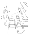
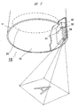
- FIG. 3 shows, as an example, the internal configuration of the pendant type illumination device 10 with a video projection function shown in FIG. 1. As is clear from this figure, for example, it is formed by molding a synthetic resin mold. In the inside of the substantially cylindrical or conical main body (or also referred to as a housing) (shade) 11, as described in detail below, for example, a plurality of semiconductor light emitting elements (LEDs) are arranged in a planar shape.
- LEDs semiconductor light emitting elements
- Illuminating light source 20 (here, the description of each semiconductor light emitting element is omitted, and the mounting position is indicated by a broken-line circle), and a small projector for projecting and displaying various images, in particular, A projector optical unit (optical engine) 30 that is a main part of the projector is provided.
- symbol 12 in a figure is provided so that the lower opening part of the said main body 11 may be covered, and what is called a diffuser plate for diffusing the illumination light from the said light source 20 for illumination and irradiating uniformly downward is provided.
- a diffuser plate for diffusing the illumination light from the said light source 20 for illumination and irradiating uniformly downward is provided.
- the outer shape of the main body (shade) 11 has been described as a cylinder or a cone.
- the present invention is not limited to this, and may have other shapes, for example, a box shape.
- the internal configuration of the ceiling-type illumination device with video projection function 10 ′ shown in FIG. 2 is also similar to the above-described pendant-type illumination device with video projection function.
- An illumination light source in which a plurality of semiconductor light emitting elements (LEDs) are arranged in a planar shape inside a main body (an enclosure or a shade) formed by molding, and a small projector for projecting and displaying various images. Needless to say, the optical unit and the diffusion plate are provided.
- the outer shape of the main body (shade) has been described as a rectangular box shape. However, the present invention is not limited to this, and other shapes such as a disk or an ellipse are also used. There may be.
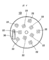
- FIG. 4 shows a specific example of the illumination light source 20 described above.
- This figure shows the lighting device 10 with the pendant image projection function shown in FIG. 1 from below with the diffusion plate 12 removed.
- FIG. As is clear from this figure, for example, a plurality (10 in this example) of semiconductor light emitting elements (LEDs) 22 are provided on the surface of the disk-shaped substrate 21 made of a metal having excellent thermal conductivity. They are arranged and mounted so that substantially uniform irradiation light can be obtained.
- LEDs semiconductor light emitting elements
- the diffusion plate 12 described above is attached so as to cover the opening below the illumination light source 20 by a transparent or translucent member that scatters the irradiation light, and a part thereof, That is, a transmission window 14 that is an opening for transmitting the image light or a transparent window is formed at a position where the image light from the optical unit 30 of the projector is projected.
- a camera as a sensor attached to a part of the optical unit may be provided in order to realize the interactive function of the optical unit.
- the camera detects, for example, an infrared light component in an imaging range including the display surface 61. According to this, the user's action is photographed or from an operation article operated by the user. By detecting the reflected light, the user's operation content can be detected.
- the main body 11 of the lighting device 10 with the video projection function is suspended from the ceiling surface to a desired position on the upper surface of the pendant lighting device 10 with the video projection function.
- the holder 40 for holding in a state is fixed, and the holder 40 will be described below with reference to the attached FIG.
- one end (lower end) of the holder 40 is fixed to the bottom surface (upper end face) constituting the main body 11 of the lighting device 10 with the video projection function, and the holder 40 is attached to the other end (upper end).
- the disk-shaped attachment 45 for fixing to a ceiling surface is provided, and it fixes to a ceiling surface firmly with the screw 46, the screw hole 47, etc., for example.
- the illumination device 10 with a projection function it has been found that when the illumination device body 11 with a video projection function is shaken or rotated, a situation in which a projection image is shaken and a function as a display device cannot be sufficiently achieved can occur.
- the holder 40 described above is formed of a so-called rigid member such as a hollow metal tube made of aluminum or the like, and thus a preferable result was obtained.
- the light source 20 composed of the semiconductor light emitting element (LED) and the power cord 48 for supplying power to the optical unit 30 inside the tube constituting the holder 40, and further, If necessary, by storing a cable or the like for supplying a video signal, it is not necessary to squeeze the power cord or cable outside, and the illumination device with a video projection function is excellent in design. It can be.
- the lower end of the tubular body constituting the holder 40 is opened to the internal space of the illumination device body 11 with the image projection function, that is, the air inside the illumination device body 11 with the image projection function is retained by the holder 40.
- Is configured to be able to flow into the tube body heat generated from the light source 20 and the optical unit 30 housed inside the main body is guided to the tube body by a so-called chimney effect, and formed at the upper part of the tube body. It is possible to discharge to the outside through the slit-shaped opening 49 (see the white arrow in the figure). According to this, it becomes possible to contribute to the more efficient cooling of the illuminating device 10 with a video projection function.
- the tube constituting the holder 40 a plurality of slidable tubes (pipes) having different diameters are concentrically combined, and a fixing portion is provided in a part thereof. Therefore, it is also possible to use a tubular body whose overall length can be adjusted. According to this, since the height of the illumination device 10 with a video projection function suspended from the ceiling 50 can be freely adjusted, it is possible to realize an illumination device with a video projection function that is further excellent in its usability. It becomes possible.
- FIG. 6 is a block diagram showing a detailed example of a circuit configuration that constitutes the inside of the optical unit 30, a so-called projection type video display device.
- Projection optical system 101 is an optical system that projects an image onto display surface 61, and includes a lens and / or a mirror.
- the display element 102 (reference numeral 32 in FIG. 3) is an element that generates a projected image, and uses a transmissive liquid crystal panel, a reflective liquid crystal panel, a DMD (Digital Micromirror Device: registered trademark) panel, or the like.
- the display element driving unit 103 sends a drive signal corresponding to the video signal to the display element 102.
- the light source 105 (reference numeral 31 in FIG. 3) generates illumination light for projection, and uses a high-pressure mercury lamp, a xenon lamp, an LED light source, a laser light source, or the like.
- the power source 106 supplies power to the light source 105.
- the illumination optical system 104 condenses the illumination light generated by the light source 105, makes it more uniform, and irradiates the display element 102.
- the cooling unit 115 cools each part, such as the light source 105, the power source 106, or the display element 102, which is in a high temperature state, using an air cooling method or a liquid cooling method as necessary.
- An operation signal input unit 107 is an operation button on the apparatus main body or a light receiving unit of a remote controller, and inputs an operation signal from a user.
- the video input unit 131 connects an external video output device and inputs video data.
- the audio input unit 133 connects an external video output device and inputs audio data.
- the audio output unit 140 can perform audio output based on the audio data input to the audio input unit 133. Further, the audio output unit 140 may output a built-in operation sound or an error warning sound.
- the communication unit 132 is connected to an external information processing apparatus and inputs / outputs various control signals.
- the nonvolatile memory 108 stores data for various operations in the interactive function, display icons, calibration data to be described later, and other data used for the projector function.
- the memory 109 stores video data to be projected and control data for the apparatus.
- the control unit 110 controls the operation of each unit in the apparatus. Particularly, the interactive function is executed by controlling the sensor 150 and the interactive function unit 120.
- the sensor 150 is a camera that captures a range that overlaps the video projection area on the display surface 61, and can detect reflected light from the operation article by detecting an infrared light component.
- the cut wavelength of the optical filter of the sensor 150 to the visible light wavelength region (for example, setting in the middle of the red visible light region), some visible light components other than infrared light (that is, the display screen) It is also possible to photograph a projected image) together with an infrared light component.
- the interactive function unit 120 is a part that performs an interactive operation such as writing a character or a figure in the video area when the user operates a light emitting pen or a finger.
- the infrared image acquired from the sensor 150 is analyzed to calculate the position of the light-emitting pen or finger (the position operated by the user), the operation icon is synthesized in the projected video, or based on the user's operation. It has a function of executing an application that can be operated with a light-emitting pen or a finger, such as an application that performs drawing processing or the like, or an application that operates an image input from an external video output device.
- the imaging range of the sensor 150 and the range of the image projected on the display surface 61 are unlikely to coincide with each other. Therefore, when calculating the position operated (drawn) by the user, it is necessary to convert the coordinates in the imaging range of the sensor 150 and the coordinate position in the video projected on the display surface 61. Therefore, the interactive function unit 120 has a function of performing the conversion process and a process for creating conversion table data (calibration data) for the conversion process.
- the video input unit 131 connects an external video output device and inputs video data.
- the audio input unit 133 connects an external video output device and inputs audio data.
- the communication unit 132 is connected to an external information processing apparatus and inputs / outputs various control signals.
- the light from the light source 31 (for example, a semiconductor light emitting element (LED)) of the optical unit 30 is, for example, DMD (Digital Micromirror Device: registered trademark) or the like.
- a display unit 32 composed of a reflective image display element (or a transmissive image display element such as a liquid crystal panel), and is projected to the outside via a projection optical system 34 including various lenses.
- an image projected downward from the optical unit 30 is displayed in a range in which at least a part overlaps with an irradiable region of the illumination light by the illumination device 10 with the image projection function.
- the details of the optical unit 30 will be described later again, but prior to this, in the following, image projection between the optical unit 30 and the above-described illumination light source 20 and further the diffusion plate 12 will be described.
- the positional relationship within the main body (shade) 11 of the illumination device 10 with a function will be described.
- the circuit configuration shown in FIG. 6 described above may be assembled on, for example, a circuit board and disposed inside the optical unit 30 or may be arranged outside (for example, an illumination light source described in FIG. 10 and thereafter). 20 may be disposed on the back surface of the disk-shaped substrate 21 on which 20 is disposed. ⁇ Definition of projector optical unit arrangement>
- the vertical placement of the optical unit is a so-called configuration in which the light beam from the display element (reference numeral 32 in FIG. 3) constituting the projector includes various optical elements such as lenses.
- the incident direction of the light beam or the optical axis of the projection optical system (34) on which the light beam is incident is approximately with respect to a horizontal plane (a surface perpendicular to the surface of the drawing).
- the optical image of the display element (32) can be formed on the horizontal plane by the light emitted from the projection optical system (34).
- the display element (32) may be a transmission type or a reflection type. There is something.
- various types of optical systems are known, such as one with a single display element (32) layout and one with multiple display elements.
- the position of the optical image of the display element on the horizontal plane can be changed by changing the relative position setting of the center position of the display element (32) and the optical axis of the projection system (34) in the xy plane. It becomes possible to change. As a result, the position of the projected image on the horizontal plane can be freely set according to the design needs.
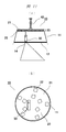
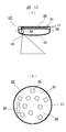
- FIGS. 9A and 9B are a side cross-sectional view and a bottom view of a pendant type illumination device 10 with a video projection function.
- a substrate 21 of an illuminating light source 20 having a plurality of semiconductor light emitting elements (LEDs) 22 is attached to the bottom surface inside a housing 11 that is a main body.
- a diffusion plate 12 is attached to the lower opening surface of the figure so as to cover it.
- the optical unit 30 is disposed so as to be located at a substantially central portion of the illumination light beam.
- an opening or a transmission window 14 is provided on the diffusion plate 12 at a position where the projection light is emitted downward from the optical unit 30. If there is a diffusion effect on the entire surface of the diffusing plate 12 without providing an opening or a transmission window, the projection image emitted from the optical unit 30 is diffused, and an image can be formed on the image projection target surface such as a table or a desk. Because it will disappear.
- the opening or the portion of the transmission window 14 may be an opening in which the diffusion plate 12 is cut out, or may be a transmissive substance such as glass having no diffusion effect.
- a transmissive window formed of a transmissive material or the like it can be configured such that dust or the like is less likely to enter the diffusing plate 12, but in order not to affect the projected image emitted from the optical unit 30 as much as possible.
- the coating In the wavelength range of the projection light emitted from the unit 30, the coating should have a characteristic as flat as possible in the spectral range.
- the opening or the transmission window 14 does not need to be directly connected to the diffusion plate 12, and in order to make the shadow of the optical unit 30 on the diffusion plate 12 difficult to see, the opening or the transmission window 14 and the diffusion plate 12.
- An area such as a decorative board may be provided between the two.
- the opening or the transmission window 14 is a passage opening or transmission necessary for emitting image projection light projected from the optical unit 30 arranged in a space formed by the housing 11 and the diffusion plate 12. It is a mouth, and the position thereof may be the diffusion plate 12 or a part of another structure.
- the optical unit 30 can be thinned in a direction parallel to the horizontal plane, so that the shadow formed by the optical unit 30 with respect to the illumination area from the illumination light source 20 to the diffusion plate 12 can be reduced. It becomes possible to reduce the ratio. This suppresses the appearance quality of the lighting device from being deteriorated due to the influence of the shadow of the optical unit 30 formed on the diffusion plate 12 (that is, an uncomfortable feeling as a lighting device due to the shadow on the diffusion plate 12). It becomes possible to do. Moreover, even when the above-described casing 11 is formed of a diffusion plate, the shadow of the optical unit 30 is not noticeable, and it is possible to suppress deterioration in the appearance quality of the illumination device.
- the diffusion plate 12 has an effect of converting light from a plurality of semiconductor light emitting elements (LEDs) 22 having a small light emitting area into diffused light having a more uniform light distribution characteristic. Increasing the number of semiconductor light emitting elements (LEDs) 22 can provide more uniform diffused light, but increases the cost. When the number of the plurality of semiconductor light emitting elements (LEDs) 22 is fixed, as the distance between the plurality of semiconductor light emitting elements (LEDs) 22 and the diffusion plate 12 increases, the semiconductor light emitting elements (LEDs) 22 arranged adjacent to each other. Since the light emission from each other overlaps, more uniform diffused light can be obtained. Therefore, in order to achieve both cost performance and uniform acquisition of diffused light, the distance between the plurality of semiconductor light emitting elements (LEDs) 22 and the diffusion plate 12 should be as long as possible.
- the projection optical system of the optical unit 30 is an enlargement projection system
- the projection light projected downward from the optical unit 30 increases as it advances downward.
- the position where the projection light is output downward from the optical unit 30 in the example of FIGS. 7 and 8, the position where the projection light is emitted downward from the projection optical system 34
- the distance should be as short as possible. If this distance is increased, it is necessary to increase the area of the opening or transmission window 14 provided in a part of the diffusion plate 12 due to the expansion of the image projection light, and the effect of diffusing the illumination light in that part cannot be obtained. Because it ends up.
- the optical unit 30 is diffused with the casing 11 as shown in FIG. What is necessary is just to arrange
- FIG. In this way, the distance between the plurality of semiconductor light emitting elements (LEDs) 22 and the diffusion plate 12 can be secured, and the position where the projection light is output downward from the optical unit 30 and the opening or transmission window.
- the distance to 14 can be shortened, and all the balance of cost performance, uniformity of diffused light, and downsizing of the opening or the transmission window can be more suitably obtained.
- the emission position of the image emission light from the optical unit 30 is arranged between the light source 20 and the opening or the transmission window 14.
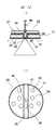
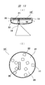
- FIGS. 10A and 10B are a side cross-sectional view and a bottom view of the pendant type illumination device 10 with a video projection function.
- the optical unit 30 attached to the inside of the housing 11 is illuminated. It arrange
- the optical unit 30 is arranged so as to be positioned at the end of the illumination light beam, and the optical axis of the projection optical system and the position of the center of the display element are relative to each other in the horizontal direction in the optical unit 30. Accordingly, the center of the projected image is projected closer to the center of the illumination light beam of the illumination light source 20 with respect to the exit of the projection optical system of the projector.
- a so-called stationary projector which is usually arranged on a desk, can be used as it is.
- the illumination device with a video projection function in FIG. 10 has a structure suitable for cost reduction.
- This effect is also the same effect that occurs in other configuration examples in which the optical unit 30 is positioned at the end of the downward illumination light beam.
- the optical unit 30 can be arranged at an intermediate position between the layout (array) of FIG. 9 and the layout (array) of FIG. In such a case as well, as in the above example, it is possible to suppress a decrease in the quality of the appearance of the lighting device.
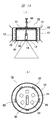
- the central portion of the substrate 21 for the illumination light source 20 having a plurality of semiconductor light emitting elements (LEDs) 22 is bent into a substantially “U” shape to form the groove 25.
- positioned the optical unit 30 in that (namely located in the approximate center part of illumination light beam) is shown.
- the optical unit 30 is further disposed in the groove 25 so that the shadow of the optical unit 30 itself is reflected on the surface of the diffusion plate 12 having a white surface. Therefore, it is possible to further suppress the deterioration of the appearance quality of the lighting device.
- An opening (or transmission window) 26 for transmitting the projection light from the optical unit 30 is formed at a part of the groove 25, that is, at a position where the optical unit 30 is disposed.
- the outer surface of the groove 25 (the surface opposite to the surface where the optical unit 30 is stored) on which the illumination light from the plurality of semiconductor light emitting elements (LEDs) 22 is reflected has a reflectance such as white coating or mirror coating.
- a reflectance such as white coating or mirror coating.
- the diffusion plate 12 may be provided on the bottom surface of the groove portion 25, but the diffusion plate 12 may be absent from the bottom surface portion of the groove portion 25. In the example of FIG. 12, the diffusion plate 12 is divided into two by the bottom surface of the groove portion 25.
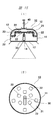
- FIGS. 13A and 13B show a configuration in which a plurality of semiconductor light emitting elements (LEDs) 22 are provided on both surfaces of a substrate 21 for a light source 20 for illumination. Thereby, the structure which can irradiate upward also in addition to illumination light is shown.
- the arrangement of the optical unit 30 is the end of the illumination beam of the illumination light downward, but the arrangement of the optical unit 30 is arranged at the center of the illumination beam of the illumination light downward. May be. According to such a configuration, it is possible to irradiate illumination light also above the illumination device 10 with a video projection function, and the upper illumination can also illuminate the ceiling or the like, and thus functions as indirect illumination (ceiling-side indirect illumination function).
- the diffusion plate 12 (lower diffusion plate) on the opening surface of the lower surface of the housing (shade) 11, the diffusion plate 12 (upper diffusion plate) so as to cover the opening surface of the upper surface of the housing (shade) 11. ) Is attached.
- a mode in which only the projected image is irradiated downward a mode in which irradiation light is irradiated downward and no image is projected, a mode in which irradiation light is irradiated and no image is projected, and irradiation light is irradiated upward and downward
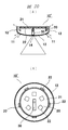
- the end portion of the substrate 21 for the illumination light source 20 is formed in a cylindrical shape by extending in the vertical direction, and a plurality of semiconductor light emitting elements (LEDs) 22 are attached to the bottom surface thereof.
- LEDs semiconductor light emitting elements
- the optical unit 30 is arranged so as to be positioned at a substantially central portion of the downward illumination light beam. Note that the arrangement of the optical unit 30 may not be the substantially central portion of the illumination light beam of the downward illumination light. You may arrange
- a diffusion plate 12 (side diffusion plate) is also attached to the outer periphery of the housing 11. According to this configuration, in addition to the above-described effect of placing the optical unit vertically, it is possible to irradiate illumination light to the side of the illumination device 10 with a video projection function (a wide range of illumination functions).
- the illumination function has a plurality of irradiation directions having different directions, so that the irradiation light and the projection image of the image projection function of the illumination function as described in FIG. 13.
- a plurality of modes may be switched for.
- the end portion of the substrate 21 for the illumination light source 20 is formed in a cylindrical shape by extending in the vertical direction, and further extended in the horizontal direction by a flange portion. Is forming. Further, a plurality of semiconductor light emitting elements (LEDs) 22 are attached to the upper and lower surfaces of the substrate 21, the outer peripheral surface of the cylindrical portion, and the lower surface of the collar portion.
- LEDs semiconductor light emitting elements
- the arrangement of the optical unit 30 does not have to be in the substantially central portion of the illumination light flux of the downward illumination light. You may arrange
- an opening is formed so as to cover the upper surface of the casing (shade) 11 and a part of the outer periphery (upper part). An upper peripheral diffusion plate is attached.
- the illumination function has a plurality of irradiation directions having different directions, so that the irradiation light in the plurality of irradiation directions of the illumination function and the projected image of the video projection function are described as described in FIG. 13.
- a plurality of modes may be switched for.
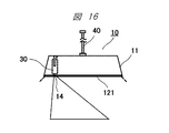
- FIG. 16 shows a planar light-emitting body 121 such as EL (electroluminescence) instead of the substrate 21 for the illumination light source 20 having a plurality of semiconductor light-emitting elements (LEDs) 22 in the configuration of FIG. Is adopted, and the light emitter 121 is arranged at the lower end of the above-described housing 11 (that is, the position of the diffusion plate 12 in FIG. 9).
- EL electroluminescence
- the illumination light is emitted from the light emitter 121 that covers the lower end of the housing 11 in which the optical unit 30 is housed, so that the internal optical unit 30 is recognized from the outside. Therefore, it is possible to more reliably suppress the deterioration of the appearance quality as the lighting device.
- the optical unit 30 is disposed so as to be positioned at the end portion of the downward illumination light beam is shown, but the present invention is not limited to this, and further, the substantially central portion thereof. Even if it is arranged at an intermediate position, the same effect can be achieved.
- the light emitter 121 is configured to cover the lower end portion of the housing 11, but the lower side end of the side surface of the housing 11 extends downward from the light emitter 121 to provide a deep shade. It may be configured.
- FIG. 16 a plurality of semiconductor light emitting elements (LEDs) 22 are eliminated from FIG. 9, and a planar light emitter 121 is disposed in the diffusion plate 12 portion.
- LEDs semiconductor light emitting elements
- FIG. 15 it is also possible to eliminate the plurality of semiconductor light emitting elements (LEDs) 22 and arrange the planar light emitter 121 on the diffusion plate 12. is there.
- the illumination device 10 ′ with a video projection function that has the planar light-emitting body 121 as an illumination function and can irradiate illumination light in a plurality of irradiation directions. In this case, as in FIG.
- Mode switching control may be performed.
- FIGS. 17A and 17B are a side cross-sectional view and a bottom view of a ceiling-type illumination device 10 ′ with a video projection function.
- a substrate 21 of an illuminating light source 20 including a plurality of semiconductor light emitting elements (LEDs) 22 is attached to the bottom surface inside a housing 11 that is a main body.
- a diffusion plate 12 is attached to the lower opening side of the figure so as to cover it.
- the optical unit 30 is disposed so as to be located at a substantially central portion of the illumination light beam.
- the optical unit 30 can be thinned in a direction parallel to the horizontal plane, so that the shadow formed by the optical unit 30 with respect to the illumination area from the illumination light source 20 to the diffusion plate 12 can be reduced. It becomes possible to reduce the ratio. This suppresses the appearance quality of the lighting device from being deteriorated due to the influence of the shadow of the optical unit 30 formed on the diffusion plate 12 (that is, an uncomfortable feeling as a lighting device due to the shadow on the diffusion plate 12). It becomes possible to do. Moreover, even when the above-described casing 11 is formed of a diffusion plate, the shadow of the optical unit 30 is not noticeable, and it is possible to suppress deterioration in the appearance quality of the illumination device.
- 18A and 18B are a side cross-sectional view and a bottom view of a ceiling-type illumination device 10 ′ with a video projection function.
- an optical unit 30 attached to the inside of a housing 11 is It is arranged so as to be located at the end of the illumination light beam.
- the optical unit 30 is placed between the layout (array) in FIG. 17 and the layout (array) in FIG. Placed in position.
- layouts arrangements
- the end of the substrate 21 for the illumination light source 20 is formed in a cylindrical shape by extending in the vertical direction,
- a plurality of semiconductor light emitting elements (LEDs) 22 are attached to the bottom surface, and a plurality of semiconductor light emitting elements (LEDs) 22 are also attached to the outer peripheral surface of the cylindrical substrate 21.
- the optical unit 30 is arranged so as to be positioned at a substantially central portion of the downward illumination light beam. Note that the arrangement of the optical unit 30 may not be the substantially central portion of the illumination light beam of the downward illumination light. You may arrange
- a diffusion plate 12 (side diffusion plate) is also attached to the outer periphery of the housing 11.
- the illumination function has a plurality of irradiation directions with different directions, and as described in FIG. 13, the irradiation light in the plurality of irradiation directions of the illumination function and the projected image of the video projection function A plurality of modes may be switched for.
- the illumination light source 20 including a plurality of semiconductor light emitting elements (LEDs) 22
- a planar light-emitting body 121 such as EL (electroluminescence) is employed and the light-emitting body 121 is disposed at the position of the diffusion plate 12 in FIG. 18 is shown.
- the illumination light is emitted from the light emitter 121 that covers the lower end of the housing 11 in which the optical unit 30 is housed, so that the internal optical unit 30 is not recognized from the outside. It is possible to more reliably suppress the deterioration of the appearance quality as the lighting device.
- the optical unit 30 is disposed so as to be positioned at the end of the downward illumination light beam, but the present invention is not limited thereto, Even if it is arranged at an intermediate position, the same effect can be achieved.
- the plurality of semiconductor light-emitting elements (LEDs) 22 are eliminated from FIG. 18, and a planar light-emitting body 121 is disposed in the diffusion plate 12 portion.
- a planar light emitting body 121 is disposed on the diffusion plate 12, and the planar light emitting body 121 is It is also possible to divide into a downward irradiation region and a side light irradiation region according to the angle of the surface.
- the planar light emitter 121 has an illumination function, and a plurality It is possible to realize an illumination device 10 ′ with a video projection function that can irradiate illumination light in the irradiation direction. In this case, similarly to FIG. 13, since it has an illumination function having a plurality of irradiation directions with different directions, as described in FIG. Mode switching control may be performed.
- the illumination device with a video projection function according to various embodiments of the present invention has been described.
- the present invention is not limited to the above-described embodiments, and includes various modifications.
- the above-described embodiments are described in detail for the entire system in order to explain the present invention in an easy-to-understand manner, and are not necessarily limited to those having all the configurations described.
- a part of the configuration of one embodiment can be replaced with the configuration of another embodiment, and the configuration of another embodiment can be added to the configuration of one embodiment.
- SYMBOLS 10 Illuminating device, 11 ... Main body (shade) (shade), 12 ... Diffuser, 20 ... Light source for illumination, 22 ... Semiconductor light emitting element (LED), 30 ... Optical unit, 31 ... Light source, 32 ... Display part, 34 ... projection optics.
Landscapes
- Engineering & Computer Science (AREA)
- General Engineering & Computer Science (AREA)
- Physics & Mathematics (AREA)
- Optics & Photonics (AREA)
- General Physics & Mathematics (AREA)
- Architecture (AREA)
- Projection Apparatus (AREA)
- Non-Portable Lighting Devices Or Systems Thereof (AREA)
- Transforming Electric Information Into Light Information (AREA)
Abstract
Description
<ペンダント型およびシーリング型の映像投射機能付き照明装置>
<プロジェクタ光学ユニットの配置の定義>
<光学ユニットの縦置き>
<ペンダント型の映像投射機能付き照明装置>
<シーリング型の映像投射機能付き照明装置>
Claims (14)
- 照明光を発する照明装置であって、
筺体の内部に配置される前記照明光を生成するための光源と、
当該筺体の一部に取り付けた拡散板であって、前記光源からの照明光を拡散する拡散板と、
前記筺体と前記拡散板の一部が形成する空間の内部に配置され、投射面に映像を投射するプロジェクタと、
を備え、
前記プロジェクタを構成する光学ユニットが、前記プロジェクタが備える表示素子から前記プロジェクタの投射光学系へ入射する光束の入射方向が、略鉛直方向、または水平面に平行な方向よりも鉛直方向により近い方向となる状態、または前記プロジェクタが備える表示素子からの光束が入射する前記投射光学系の光軸が、略鉛直方向、または水平面に平行な方向よりも鉛直方向により近い方向となる状態で配置されている、照明装置。 - 請求項1に記載した照明装置において、
前記プロジェクタは水平面を映像投射面として映像を投射可能であり、
前記プロジェクタにおける前記水平面での映像投射領域と、前記光源により生じた光を拡散した照明光による前記水平面での照明範囲の少なくとも一部が重畳する、照明装置。 - 請求項1に記載した照明装置において、
前記光学ユニットからの投射映像光が前記筺体と前記拡散板の一部が形成する空間の内部から出射するための開口部または透過窓を更に備え、
鉛直方向の配置において、前記光学ユニットからの映像出射光の出射位置が前記光源と前記開口部または透過窓との間に配置される、照明装置。 - 請求項1に記載した照明装置において、
前記照明装置は、ペンダント型の照明装置である、照明装置。 - 請求項1に記載した照明装置において、
前記照明装置は、シーリング型の照明装置である、照明装置。 - 請求項1に記載した照明装置において、
前記光学ユニットは、前記照明装置からの照明光束の中央部に位置するように配置されている、照明装置。 - 請求項1に記載した照明装置において、
前記光学ユニットは、前記照明装置からの照明光束の端部に位置するように配置されている、照明装置。 - 請求項1に記載した照明装置において、
前記光学ユニットは、前記照明装置からの照明光束の中央部と端部の間に位置するように配置されている、照明装置。 - 請求項1に記載した照明装置において、前記光源には、前記筺体の一部に取り付けた基板の下面に配置されて取り付けた発光素子が含まれる、照明装置。
- 請求項9に記載した照明装置において、
前記基板は、更に、その端部から垂直方向に延長した側面を有し、前記側面の外側に発光素子を備えている、照明装置。 - 請求項1に記載した照明装置において、
前記光源には、前記筺体の一部に取り付けた基板の下面と上面に配置されて取り付けた発光素子が含まれる、照明装置。 - 請求項1に記載した照明装置において、
前記筺体の一部に取り付けられた前記拡散板を、照明光を発生する前記光源とした、照明装置。 - 請求項12に記載した照明装置において、
前記照明光を発生する前記光源をELで構成した、照明装置。 - 請求項1に記載した照明装置において、
前記照明光を発生する前記光源をLEDで構成した、照明装置。
Priority Applications (4)
| Application Number | Priority Date | Filing Date | Title |
|---|---|---|---|
| JP2016565850A JP6334001B2 (ja) | 2014-12-26 | 2014-12-26 | 照明装置 |
| PCT/JP2014/084696 WO2016103512A1 (ja) | 2014-12-26 | 2014-12-26 | 照明装置 |
| US15/539,243 US10260691B2 (en) | 2014-12-26 | 2014-12-26 | Illumination apparatus |
| CN201480084379.7A CN107110451B (zh) | 2014-12-26 | 2014-12-26 | 照明装置 |
Applications Claiming Priority (1)
| Application Number | Priority Date | Filing Date | Title |
|---|---|---|---|
| PCT/JP2014/084696 WO2016103512A1 (ja) | 2014-12-26 | 2014-12-26 | 照明装置 |
Publications (1)
| Publication Number | Publication Date |
|---|---|
| WO2016103512A1 true WO2016103512A1 (ja) | 2016-06-30 |
Family
ID=56149594
Family Applications (1)
| Application Number | Title | Priority Date | Filing Date |
|---|---|---|---|
| PCT/JP2014/084696 Ceased WO2016103512A1 (ja) | 2014-12-26 | 2014-12-26 | 照明装置 |
Country Status (4)
| Country | Link |
|---|---|
| US (1) | US10260691B2 (ja) |
| JP (1) | JP6334001B2 (ja) |
| CN (1) | CN107110451B (ja) |
| WO (1) | WO2016103512A1 (ja) |
Cited By (3)
| Publication number | Priority date | Publication date | Assignee | Title |
|---|---|---|---|---|
| CN107121883A (zh) * | 2017-06-15 | 2017-09-01 | 北京数科技有限公司 | 一种投影及照明装置 |
| KR20220018859A (ko) * | 2020-08-07 | 2022-02-15 | 우영씨티(주) | 시인성이 강화된 경광등 및 시인성이 강화된 경광등 시스템 |
| JP2022046123A (ja) * | 2020-09-10 | 2022-03-23 | セイコーエプソン株式会社 | プロジェクター付き照明装置および照明装置 |
Families Citing this family (1)
| Publication number | Priority date | Publication date | Assignee | Title |
|---|---|---|---|---|
| WO2019058521A1 (ja) * | 2017-09-22 | 2019-03-28 | popIn株式会社 | プロジェクタおよびプロジェクタシステム |
Citations (5)
| Publication number | Priority date | Publication date | Assignee | Title |
|---|---|---|---|---|
| JPH11144510A (ja) * | 1997-11-06 | 1999-05-28 | Matsushita Electric Ind Co Ltd | 照明装置 |
| JP2007027072A (ja) * | 2005-07-12 | 2007-02-01 | Nobuichi Tsubota | 天井用led照明器具 |
| JP2008077979A (ja) * | 2006-09-21 | 2008-04-03 | Toshiba Lighting & Technology Corp | 照明装置 |
| JP2012186118A (ja) * | 2011-03-08 | 2012-09-27 | Toshiba Lighting & Technology Corp | 照明器具 |
| JP2014120400A (ja) * | 2012-12-18 | 2014-06-30 | Iris Ohyama Inc | Led照明装置 |
Family Cites Families (15)
| Publication number | Priority date | Publication date | Assignee | Title |
|---|---|---|---|---|
| JPH07264527A (ja) | 1994-03-17 | 1995-10-13 | Hitachi Ltd | 液晶プロジェクタ |
| JPH09139905A (ja) | 1995-11-14 | 1997-05-27 | Nikon Corp | 投写表示装置 |
| JP2003016831A (ja) | 2001-06-29 | 2003-01-17 | Hittsu Kenkyusho:Kk | 通信機能モジュール |
| JP2004078150A (ja) | 2002-06-21 | 2004-03-11 | Seiko Epson Corp | 投射型表示装置 |
| JP4101571B2 (ja) | 2002-07-04 | 2008-06-18 | 株式会社日立製作所 | 投射型映像表示装置用支持装置 |
| JP2004184768A (ja) | 2002-12-04 | 2004-07-02 | Kanebo Ltd | プロジェクタ装置 |
| JP2004233692A (ja) | 2003-01-30 | 2004-08-19 | Dainippon Printing Co Ltd | プロジェクタ装置 |
| JP2004336615A (ja) | 2003-05-12 | 2004-11-25 | Plus Vision Corp | プロジェクタ及びプロジェクタ用設置冶具 |
| JP2006086024A (ja) | 2004-09-16 | 2006-03-30 | Nec Lighting Ltd | 照明器具 |
| JP2006162832A (ja) | 2004-12-06 | 2006-06-22 | Seiko Epson Corp | プロジェクタ |
| JP2008185757A (ja) | 2007-01-30 | 2008-08-14 | Seiko Epson Corp | プロジェクタ、投影システム及び照明器具 |
| JP2009145526A (ja) | 2007-12-13 | 2009-07-02 | Seiko Epson Corp | プロジェクタ及び画像表示システム |
| US8662675B2 (en) * | 2010-07-09 | 2014-03-04 | Texas Instruments Incorporated | Compact image offset projection lens |
| CN102540661B (zh) * | 2010-12-28 | 2014-08-06 | 中强光电股份有限公司 | 投影装置 |
| JP6089551B2 (ja) | 2012-10-09 | 2017-03-08 | セイコーエプソン株式会社 | 照明装置 |
-
2014
- 2014-12-26 JP JP2016565850A patent/JP6334001B2/ja active Active
- 2014-12-26 US US15/539,243 patent/US10260691B2/en active Active
- 2014-12-26 WO PCT/JP2014/084696 patent/WO2016103512A1/ja not_active Ceased
- 2014-12-26 CN CN201480084379.7A patent/CN107110451B/zh active Active
Patent Citations (5)
| Publication number | Priority date | Publication date | Assignee | Title |
|---|---|---|---|---|
| JPH11144510A (ja) * | 1997-11-06 | 1999-05-28 | Matsushita Electric Ind Co Ltd | 照明装置 |
| JP2007027072A (ja) * | 2005-07-12 | 2007-02-01 | Nobuichi Tsubota | 天井用led照明器具 |
| JP2008077979A (ja) * | 2006-09-21 | 2008-04-03 | Toshiba Lighting & Technology Corp | 照明装置 |
| JP2012186118A (ja) * | 2011-03-08 | 2012-09-27 | Toshiba Lighting & Technology Corp | 照明器具 |
| JP2014120400A (ja) * | 2012-12-18 | 2014-06-30 | Iris Ohyama Inc | Led照明装置 |
Cited By (6)
| Publication number | Priority date | Publication date | Assignee | Title |
|---|---|---|---|---|
| CN107121883A (zh) * | 2017-06-15 | 2017-09-01 | 北京数科技有限公司 | 一种投影及照明装置 |
| KR20220018859A (ko) * | 2020-08-07 | 2022-02-15 | 우영씨티(주) | 시인성이 강화된 경광등 및 시인성이 강화된 경광등 시스템 |
| KR102371407B1 (ko) * | 2020-08-07 | 2022-03-07 | 우영씨티(주) | 시인성이 강화된 경광등 및 시인성이 강화된 경광등 시스템 |
| JP2022046123A (ja) * | 2020-09-10 | 2022-03-23 | セイコーエプソン株式会社 | プロジェクター付き照明装置および照明装置 |
| US11733600B2 (en) | 2020-09-10 | 2023-08-22 | Seiko Epson Corporation | Illumination device with projector and illumination device |
| JP7424255B2 (ja) | 2020-09-10 | 2024-01-30 | セイコーエプソン株式会社 | プロジェクター付き照明装置および照明装置 |
Also Published As
| Publication number | Publication date |
|---|---|
| US10260691B2 (en) | 2019-04-16 |
| CN107110451B (zh) | 2019-07-23 |
| JP6334001B2 (ja) | 2018-05-30 |
| JPWO2016103512A1 (ja) | 2017-08-31 |
| CN107110451A (zh) | 2017-08-29 |
| US20170350566A1 (en) | 2017-12-07 |
Similar Documents
| Publication | Publication Date | Title |
|---|---|---|
| JP6854859B2 (ja) | 照明装置 | |
| JP6752848B2 (ja) | 照明装置 | |
| JP6429257B2 (ja) | 照明装置 | |
| CN108291711B (zh) | 照明装置 | |
| JP6334001B2 (ja) | 照明装置 | |
| WO2017056147A1 (ja) | 照明装置 | |
| JP2018028560A (ja) | 照明装置 | |
| CN107532794B (zh) | 照明装置 | |
| JP2018028965A (ja) | 照明装置 | |
| WO2016060086A1 (ja) | 照明装置 | |
| WO2016104190A1 (ja) | 照明装置 | |
| WO2016162913A1 (ja) | 照明装置 | |
| TWM464702U (zh) | 微型投影模組 |
Legal Events
| Date | Code | Title | Description |
|---|---|---|---|
| 121 | Ep: the epo has been informed by wipo that ep was designated in this application |
Ref document number: 14909114 Country of ref document: EP Kind code of ref document: A1 |
|
| ENP | Entry into the national phase |
Ref document number: 2016565850 Country of ref document: JP Kind code of ref document: A |
|
| WWE | Wipo information: entry into national phase |
Ref document number: 15539243 Country of ref document: US |
|
| NENP | Non-entry into the national phase |
Ref country code: DE |
|
| 122 | Ep: pct application non-entry in european phase |
Ref document number: 14909114 Country of ref document: EP Kind code of ref document: A1 |