WO2016103452A1 - Véhicule de transport et système de transport - Google Patents
Véhicule de transport et système de transport Download PDFInfo
- Publication number
- WO2016103452A1 WO2016103452A1 PCT/JP2014/084533 JP2014084533W WO2016103452A1 WO 2016103452 A1 WO2016103452 A1 WO 2016103452A1 JP 2014084533 W JP2014084533 W JP 2014084533W WO 2016103452 A1 WO2016103452 A1 WO 2016103452A1
- Authority
- WO
- WIPO (PCT)
- Prior art keywords
- attachment
- transport vehicle
- unit
- article
- movement
- Prior art date
Links
- 230000005484 gravity Effects 0.000 claims description 27
- 238000005259 measurement Methods 0.000 claims description 26
- 230000005540 biological transmission Effects 0.000 claims description 19
- 230000001133 acceleration Effects 0.000 claims description 8
- 230000006870 function Effects 0.000 description 48
- 238000010586 diagram Methods 0.000 description 17
- 238000000034 method Methods 0.000 description 10
- 238000004891 communication Methods 0.000 description 9
- 238000012545 processing Methods 0.000 description 5
- 238000005516 engineering process Methods 0.000 description 3
- 238000004364 calculation method Methods 0.000 description 2
- 230000000694 effects Effects 0.000 description 2
- 238000012986 modification Methods 0.000 description 2
- 230000004048 modification Effects 0.000 description 2
- 238000009434 installation Methods 0.000 description 1
- 239000000463 material Substances 0.000 description 1
- 238000005096 rolling process Methods 0.000 description 1
- 239000007787 solid Substances 0.000 description 1
Images


Classifications
-
- B—PERFORMING OPERATIONS; TRANSPORTING
- B65—CONVEYING; PACKING; STORING; HANDLING THIN OR FILAMENTARY MATERIAL
- B65G—TRANSPORT OR STORAGE DEVICES, e.g. CONVEYORS FOR LOADING OR TIPPING, SHOP CONVEYOR SYSTEMS OR PNEUMATIC TUBE CONVEYORS
- B65G1/00—Storing articles, individually or in orderly arrangement, in warehouses or magazines
- B65G1/02—Storage devices
- B65G1/04—Storage devices mechanical
- B65G1/0492—Storage devices mechanical with cars adapted to travel in storage aisles
-
- B—PERFORMING OPERATIONS; TRANSPORTING
- B65—CONVEYING; PACKING; STORING; HANDLING THIN OR FILAMENTARY MATERIAL
- B65G—TRANSPORT OR STORAGE DEVICES, e.g. CONVEYORS FOR LOADING OR TIPPING, SHOP CONVEYOR SYSTEMS OR PNEUMATIC TUBE CONVEYORS
- B65G1/00—Storing articles, individually or in orderly arrangement, in warehouses or magazines
-
- G—PHYSICS
- G05—CONTROLLING; REGULATING
- G05D—SYSTEMS FOR CONTROLLING OR REGULATING NON-ELECTRIC VARIABLES
- G05D1/00—Control of position, course or altitude of land, water, air, or space vehicles, e.g. automatic pilot
- G05D1/02—Control of position or course in two dimensions
- G05D1/021—Control of position or course in two dimensions specially adapted to land vehicles
- G05D1/0212—Control of position or course in two dimensions specially adapted to land vehicles with means for defining a desired trajectory
- G05D1/0223—Control of position or course in two dimensions specially adapted to land vehicles with means for defining a desired trajectory involving speed control of the vehicle
-
- G—PHYSICS
- G05—CONTROLLING; REGULATING
- G05D—SYSTEMS FOR CONTROLLING OR REGULATING NON-ELECTRIC VARIABLES
- G05D1/00—Control of position, course or altitude of land, water, air, or space vehicles, e.g. automatic pilot
- G05D1/02—Control of position or course in two dimensions
- G05D1/021—Control of position or course in two dimensions specially adapted to land vehicles
- G05D1/0268—Control of position or course in two dimensions specially adapted to land vehicles using internal positioning means
- G05D1/0274—Control of position or course in two dimensions specially adapted to land vehicles using internal positioning means using mapping information stored in a memory device
-
- G—PHYSICS
- G05—CONTROLLING; REGULATING
- G05D—SYSTEMS FOR CONTROLLING OR REGULATING NON-ELECTRIC VARIABLES
- G05D1/00—Control of position, course or altitude of land, water, air, or space vehicles, e.g. automatic pilot
- G05D1/02—Control of position or course in two dimensions
- G05D1/021—Control of position or course in two dimensions specially adapted to land vehicles
- G05D1/0287—Control of position or course in two dimensions specially adapted to land vehicles involving a plurality of land vehicles, e.g. fleet or convoy travelling
- G05D1/0291—Fleet control
- G05D1/0297—Fleet control by controlling means in a control room
-
- B—PERFORMING OPERATIONS; TRANSPORTING
- B65—CONVEYING; PACKING; STORING; HANDLING THIN OR FILAMENTARY MATERIAL
- B65G—TRANSPORT OR STORAGE DEVICES, e.g. CONVEYORS FOR LOADING OR TIPPING, SHOP CONVEYOR SYSTEMS OR PNEUMATIC TUBE CONVEYORS
- B65G2207/00—Indexing codes relating to constructional details, configuration and additional features of a handling device, e.g. Conveyors
- B65G2207/08—Adjustable and/or adaptable to the article size
-
- B—PERFORMING OPERATIONS; TRANSPORTING
- B65—CONVEYING; PACKING; STORING; HANDLING THIN OR FILAMENTARY MATERIAL
- B65G—TRANSPORT OR STORAGE DEVICES, e.g. CONVEYORS FOR LOADING OR TIPPING, SHOP CONVEYOR SYSTEMS OR PNEUMATIC TUBE CONVEYORS
- B65G2207/00—Indexing codes relating to constructional details, configuration and additional features of a handling device, e.g. Conveyors
- B65G2207/40—Safety features of loads, equipment or persons
Definitions
- the present invention relates to a transport vehicle for transporting articles stored in a warehouse and a transport system including the transport vehicle.
- Patent Document 1 discloses a technology in which a lifter is attached to a transport vehicle as an attachment, and the type of the lifter is changed according to the size of an article to be transported.
- Patent Document 2 discloses a technology in which a robot arm is attached to a transport vehicle and information of a camera attached to the robot arm is transmitted to the transport vehicle.
- Patent Document 1 Japanese Patent Laid-Open No. 9-272430
- Patent Document 2 Japanese Patent No. 3333963
- the transport vehicle In order to attach the attachment to the transport vehicle, the transport vehicle needs to have the performance of optimally driving all of the various attachments. For this purpose, it is necessary to partially restrict the performance of the transport vehicle in a state where the transport vehicle is mounted with a specific attachment. However, there is a problem that the restriction imposed on the transport vehicle cannot be understood unless an attachment is attached to the transport vehicle.
- the robot arm attached to the transport vehicle is not assumed to be separated from the transport vehicle, and the performance and travel control of the transport vehicle are optimized for the work of the robot arm. Has been. For this reason, when the attachment is replaced, there is a problem that the transport vehicle cannot perform optimal control according to the attachment.
- an object of the present invention is to provide a transport vehicle that can attach and detach a plurality of attachments and has a function of restricting its function according to the attached attachment.
- an aspect of the present invention is a transport vehicle that loads and moves an article, and corresponds to an attachment mounting unit on which an attachment having a predetermined function is mounted, and an attribute of the attachment
- a storage device that stores a determination criterion for determining whether there is a restriction on movement of the transport vehicle, a receiving unit that receives information about an attribute of the attachment from an attachment mounted on the attachment mounting unit, and information received by the receiving unit
- a determination unit that determines whether or not a restriction is required for movement of the transport vehicle based on the determination criterion that corresponds to the attribute of the attachment specified from the above, and when the restriction is determined to be necessary
- a control unit that controls movement of the transport vehicle.
- various attachments can be attached to and detached from the transport vehicle, and the control of the transport vehicle can be restricted according to the attached attachment.
- an operation suitable for the attached attachment can be performed.
- FIG. 1A is a functional block diagram showing a configuration of a transport system according to an embodiment of the present invention.
- the transport system includes a transport vehicle 1 and an attachment 2, and the transport vehicle 1 and the attachment 2 can communicate with each other by wire or wireless.
- the attachment 2 does not have a function limitation as long as it can be attached to the transport vehicle.
- Examples of the attachment 2 include some functions for transporting an article such as a robot arm that grabs (or adsorbs) and moves the article, a lifter that lifts the article, and a belt conveyor that carries the article and moves it laterally.
- a seat on which an operator engaged in the transportation of an article is placed can be used.
- the present invention is not limited thereto, and the transport vehicle 1 can be moved with an attachment 2 having an arbitrary function.
- an article installed (or loaded) on the attachment 2 is, for example, an attachment 2 such as an article to be gripped by a robot arm, an article to be lifted by a lifter, or an article to be moved by a belt conveyor. It is the article which becomes the work object. Moreover, when the attachment 2 is a seat, the article described in the following description is replaced with a person sitting on the seat.
- the attachment 2 has a measuring unit 101, and measures the attachment 2 and the article to be worked. The measured result is transmitted to the transport vehicle 1 via the transmission unit 102.
- the transport vehicle 1 includes a receiving unit 103 that receives information transmitted from the attachment.
- the determination unit 104 compares the information received by the reception unit 103 with the determination criterion stored in the determination criterion database (DB) 106 and determines whether or not the performance of the transport vehicle 1 is restricted.
- the determination criterion DB 106 includes performance (for example, moving speed, acceleration, moving distance, and other transport vehicles 1) related to the movement of the transport vehicle 1 to which the attachment 2 of the attribute is attached.
- performance for example, moving speed, acceleration, moving distance, and other transport vehicles
- control unit 105 receives the constraint condition from the determination unit 104 and restricts the performance of the transport vehicle 1 according to the received condition. To control.
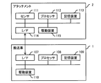
- FIG. 1B is a block diagram showing a hardware configuration of the transport system according to the embodiment of the present invention.
- the attachment 2 includes a sensor 111, a processor 112, a storage device 113, an interface (I / F) 114, and a driving device 115 which are connected to each other.
- the sensor 111 is used for measurement of the attachment 2 and an article to be worked, and may be a weight sensor, a camera, a laser sensor, or the like, for example.
- the interface 114 performs wired or wireless communication with the transport vehicle 1.
- the driving device 115 performs an operation for realizing the function of the attachment 2. For example, when the attachment 2 is a lifter or a robot arm driven by a motor, the driving device 115 may include a motor and its control circuit.
- the processor 112 executes programs stored in the storage device 113 and controls the sensor 111, the storage device 113, the interface 114, and the drive device 115 as necessary, thereby realizing various functions.
- the measurement unit 101 is a function realized by the processor 112 controlling the sensor 111
- the transmission unit 102 is a function realized by the processor 112 controlling the interface 114.
- the storage device 113 may include, for example, a volatile storage device such as a DRAM (Dynamic Random Access Memory) and a non-volatile storage device such as a flash memory, which are executed by the processor 112 to realize various functions.
- a volatile storage device such as a DRAM (Dynamic Random Access Memory)
- a non-volatile storage device such as a flash memory
- measurement data of the sensor 111, identification information and attribute information of the attachment 2, and the like may be stored.
- FIG. 1B an example in which various functions are realized by the general-purpose processor 112 executing a program is shown, but these functions can also be realized by a dedicated logic circuit or the like.
- the transport vehicle 1 includes an interface 107, a processor 108, a storage device 109, and a drive device 110 that are connected to each other.
- the interface 107 performs wired or wireless communication with the attachment 2.
- the drive device 110 is a device that moves the transport vehicle 1, and may include, for example, a plurality of wheels, a motor that drives the wheels, a battery that supplies power to the motor, a control circuit that controls them, and the like.
- the processor 108 executes various programs stored in the storage device 109, and controls the storage device 109, the interface 107, and the drive device 110 as necessary, thereby realizing various functions.
- the reception unit 103 is a function realized by the processor 108 controlling the interface 107
- the determination unit 104 is a function realized by the processor 108 based on data stored in the storage device 109
- the control unit 105 is This is a function realized by the processor 108 controlling the driving device 110.
- the function of the determination unit 104 transmitting performance information to the attachment 2 in the fifth embodiment to be described later is realized by the processor 108 controlling the interface 107.
- the storage device 109 may include, for example, a volatile storage device such as a DRAM and a nonvolatile storage device such as a flash memory, a program executed by the processor 108 to realize various functions, and their functions Data used for processing for realizing (for example, the determination criterion database 106) and the like are stored.
- FIG. 1A, 1B, 2 and 3 An example of functions of the transport system according to the first embodiment of the present invention will be described with reference to FIGS. 1A, 1B, 2 and 3.
- FIG. 1A, 1B, 2 and 3 An example of functions of the transport system according to the first embodiment of the present invention will be described with reference to FIGS. 1A, 1B, 2 and 3.
- FIG. 1A, 1B, 2 and 3 An example of functions of the transport system according to the first embodiment of the present invention will be described with reference to FIGS. 1A, 1B, 2 and 3.
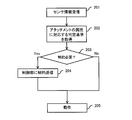
- FIG. 2 is a flowchart showing processing executed by the transport vehicle according to the first embodiment of the present invention.
- the measurement unit 101 of the attachment 2 measures the article.
- the transmitting unit 102 transmits the measurement result (that is, sensor information) to the transport vehicle 1.
- the transmission part 102 transmits the information regarding the attribute of the said attachment 2 stored in the memory
- the information related to the attribute of the attachment 2 may be information specifying the attribute itself such as the type, function, shape, size, weight, and usage of the attachment 2.
- the identification information of the attachment 2 may be used.
- an example is shown in which the transmission unit 102 transmits information on this attribute together with the sensor information. However, the transmission unit 102 is different from the transmission of the sensor information (for example, the attachment 2 is attached to the transport vehicle 1). Information on attributes) may be sent.
- the receiving unit 103 of the transport vehicle 1 receives the sensor information and the information related to the attribute from the transmitting unit 102 of the attachment 2 (Step 201), it passes the received information to the determining unit 104.
- the determination unit 104 identifies the attribute of the attachment 2 based on the received information, acquires a determination criterion corresponding to the attribute from the determination criterion DB 106 (step 202), and based on the acquired determination criterion and the received sensor information. Thus, it is determined whether or not the performance needs to be restricted (step 203).
- the determination unit 104 determines that the performance needs to be constrained, the determination unit 104 transmits the necessary constraint to the control unit 105 (step 204), and does not transmit when it is determined that the performance does not need to be constrained.
- the control part 105 controls operation
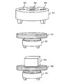
- FIG. 3 is an explanatory diagram showing an example in which a lifter is attached as an attachment to the transport vehicle according to the first embodiment of the present invention.
- the transport vehicle 301 includes one or more attachment mounting portions 304 (three in the example of FIG. 3).
- One attachment 2 that can be used independently can be attached to one attachment attachment portion 304.
- the transport vehicle 301 includes a plurality of attachment mounting portions 304 as shown in FIG. 3, the same type of attachments 2 or different types of attachments 2 may be mounted on the respective attachment mounting portions 304.
- one attachment 2 may be attached using a plurality of attachment attachment portions 304.
- each attachment mounting portion 304 may have a concave portion with a predetermined shape, and the attachment 2 may be mounted on the transport vehicle 301 by fitting the convex portion of the attachment there.
- the attachment 2 may include an electrical connector for communication.
- such a shape and mounting method of the attachment mounting portion 304 is an example, and any shape and mounting method may be adopted as long as various attachments 2 can be replaced with each attachment mounting portion 304.
- the transport vehicle 301 is equipped with a lifter 302 as an attachment 2, and the lifter 302 is equipped with a measuring instrument (not shown in FIG. 3) for measuring the weight of an article 303 loaded thereon.
- This measuring instrument corresponds to the measuring unit 101 in FIG. 1A and the sensor 111 in FIG. 1B.
- the transport vehicle 301 carries the article 303 on the lifter 302.
- the lifter moves in the vertical direction while holding the article 303 according to the work instruction.
- the speed performance of the transport vehicle is restricted according to the weight of the article 303 to be transported.
- the measuring unit 101 of the lifter 302 measures the weight of the article, and transmits the measurement result from the transmission unit 102 to the transport vehicle 301.
- the lifter 302 may transmit the weight itself as the measured weight of the article, or may transmit only a determination value as to whether or not the weight is equal to or greater than a predetermined threshold.
- the lifter 302 also transmits information regarding the attributes of the lifter 302.
- the receiving unit 103 of the transport vehicle 301 receives weight information and information on attributes from the transmitting unit 102 (step 201), and passes the received information to the determining unit 104.
- the determination unit 104 identifies the attribute of the lifter 302 based on the received information related to the attribute, and acquires a determination criterion corresponding to the specified attribute from the determination criterion DB 106 (step 202).
- the determination criterion DB 106 stores determination criteria for each type of attachment, which is one of the attachment attributes.
- the determination unit 104 receives information regarding the attribute of the attachment from the lifter 302 that is the attachment attached to the transport vehicle 301 in step 201, and the information includes information indicating that the type of the attachment is the lifter. Based on this, the type of attached attachment can be identified as a lifter. Alternatively, when the received information regarding the attachment attribute includes the identification information of the attachment, the determination unit 104 determines the type of the attachment based on the information associating the identification information of the attachment with the attribute of the attachment. May be specified. Then, the determination unit 104 acquires a determination criterion corresponding to the lifter from the determination criterion DB 106.
- the acquired determination criteria include, for example, information that associates the weight of the article 303 installed on the lifter 302 with the travel speed restriction, which is one of the performances of the transport vehicle 301. Specifically, for example, when the weight of the article 303 exceeds a predetermined threshold, the determination criterion indicates an upper limit (that is, a speed limit) of the moving speed in order to restrict the moving speed of the transport vehicle 301. Information may be included. In that case, the determination unit 104 determines whether or not the weight of the article 303 specified from the received sensor information exceeds the predetermined threshold (step 203). The speed is transmitted to the control unit 105 (step 204).
- the control unit 105 that has received this restriction controls the driving device 110 so as not to move at a high speed exceeding the speed limit received by the transport vehicle 301. Accordingly, the conveyance vehicle 301 can be moved at a low speed without dropping the article 303, and the load on the attachment 2 due to the weight and acceleration of the article 303 can be reduced.
- different values can be set as the article weight threshold according to the type of attachment 2, and the speed limit corresponding to each threshold can also be set to a different value.
- a higher value is set as the threshold of the weight of the article, or the speed limit corresponding to the threshold is higher.
- a value may be set.
- a predetermined speed limit may be set regardless of the weight of the installed article. Thereby, the movement of the conveyance vehicle 1 can be optimally controlled according to the attribute of the attachment 2 and the installed article.
- the determination criterion DB 106 may have an upper limit of acceleration corresponding to the attribute of the attachment 2 (a constant value regardless of the weight of the article, or a value according to the weight of the article. ) Is included.
- the speed limit is set according to one threshold value.
- stepwise speed limits corresponding to a plurality of threshold values may be set.
- the speed limit may be set continuously according to Or a some threshold value may be set in steps and the speed limit between threshold values may be set continuously according to the weight of articles
- the speed limit is set low, thereby preventing the article from falling and reducing the load on the attachment 2.
- a belt conveyor or a lifter is attached as the attachment 2, and the attachment 2 is equipped with a measuring device that measures the size of the article to be conveyed as the sensor 111.
- This measuring machine is, for example, a camera or a laser sensor.
- the measurement unit 101 of the attachment 2 measures the size of the article mounted on the attachment. Further, the measuring unit 101 may compare the width of the attachment 2 with the width of the article and determine whether it is larger or smaller than the attachment 2. The measurement unit 101 notifies the transmission unit 102 of the measured size of the article. The transmission unit 102 transmits the notified size of the article to the transport vehicle 1.
- the receiving unit 103 of the transport vehicle 1 receives the size of the article transmitted from the attachment 2 (step 201) and notifies the determination unit 104 of the size.
- information related to the attribute of the attachment 2 is also transmitted from the transmission unit 102 of the attachment 2 to the transport vehicle 1 and transmitted from the reception unit 103 of the transport vehicle 1 to the determination unit 104.
- map information of an area in which the transport vehicle 1 moves (for example, when the transport vehicle 1 is used inside a warehouse) is stored.
- the determination unit 104 reads a determination criterion corresponding to the attribute of the attachment 2 from the determination criterion DB 106 (step 202).
- the determination unit 104 reads out map information of an area in which the transport vehicle 1 moves as a determination reference from the determination reference DB 106.
- the read map information includes a movable body that can move in a space that can be a movement path of the transport vehicle 1 (if the attachment 2 is attached to the transport vehicle 1 and an article is installed on the attachment 2)
- the total size may be described, the size of equipment installed in the space is described, and information that can determine the size of the moving body that can pass under or next to the equipment is described.
- information indicating the size of an article that is installed in the attachment 2 and can move in each space may be described.
- the determination part 104 determines the path
- FIG. 4 is an explanatory diagram for determining whether or not the transport vehicle 1 is allowed to pass in the second embodiment of the present invention.
- Both the belt conveyor 404 and the lifter 405 correspond to the attachment 2 in FIG. 1A and the like.
- Articles 406 and 407 are installed on the belt conveyor 404 and the lifter 405, respectively.
- a shelf 401 is installed in the space in which the transport vehicle moves, and the map information includes information for specifying the installation position of the shelf 401 and the size of an object that can pass therebelow.
- the sizes (for example, heights) of articles that are installed on the respective belts and can pass under the shelf 401 may be different.
- the size of an article that can pass under the shelf 401 included in the map information read by the determination unit 104 of the transport vehicle 402 is different from that included in the map information read by the determination unit 104 of the transport vehicle 403.
- the determination unit 104 of the transport vehicle 402 determines that it can pass under the shelf 401 based on the size of the article 406 and the map information, and the determination unit 104 of the transport vehicle 403 Based on the size 407 and the map information, it is determined that it cannot pass under the shelf 401.
- step 203 it is determined that no restriction is required for the space below the shelf 401, but in the latter case, it is determined that the restriction is necessary, and the restriction (that is, passing under the shelf 401) is determined. That cannot be performed) is transmitted to the control unit 105 (step 204).
- the map information corresponding to the attachment 2 includes information indicating that the transport vehicle 1 cannot pass through the space below the shelf 401, and based on the information, it is determined that the map cannot pass under the shelf 401.
- the control unit 105 receives the passable position information acquired from the determination unit 104 and imposes restrictions on the movement route of the transport vehicle 1 in order to move and move only the passable position (step 205).
- the transport system includes the controller 3 and the transport vehicle 1 and the attachment 2 operate according to a work instruction from the controller 3. Except for differences described below, each part of the transport system of the third embodiment is the same as each part denoted by the same reference numeral in the first or second embodiment shown in FIGS. Since it has a function, those descriptions are omitted. Further, the transport vehicle 1 of the third embodiment is equipped with a robot arm as the attachment 2. Moreover, the movement area
- FIG. 5 is a block diagram showing a hardware configuration of the controller 3 according to the third embodiment of the present invention.
- the movement of the transport vehicle 1 is controlled by the controller 3.
- the controller 3 is a computer having an interface 501, a processor 502, and a storage device 503, for example.
- the interface 501 performs wired or wireless communication with the transport vehicle 1 and the attachment 2.
- the processor 502 executes the program stored in the storage device 503 and controls the interface 501 and the like as necessary, thereby realizing functions such as a work instruction unit 609 and a movement instruction unit 610 described later.
- the storage device 503 may include, for example, a volatile storage device such as a DRAM and a non-volatile storage device such as a hard disk drive, and programs executed by the processor 502 to realize various functions and their functions The data etc. used for the process for realizing are stored.
- a volatile storage device such as a DRAM
- a non-volatile storage device such as a hard disk drive
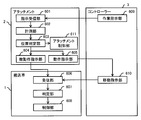
- FIG. 6 is a functional block diagram showing the configuration of the transport system according to the third embodiment of the present invention.
- the transport vehicle 1 includes a receiving unit 606, a determination unit 607, and a control unit 608.
- the processor 108 executes a program stored in the storage device 109 and controls each unit of the transport vehicle 1 as necessary. It may be realized by doing so, or by controlling a dedicated logic circuit or the like.
- the attachment 2 includes an instruction receiving unit 601, a measuring unit 602, a position determining unit 603, a fine operation instruction unit 604, an operation instruction unit 605, and an attachment control unit 611. These are realized by the processor 112 executing a program stored in the storage device 113 and controlling each part of the attachment 2 as necessary, similarly to the measurement unit 101 and the transmission unit 102 of the first embodiment. Alternatively, it may be realized by controlling a dedicated logic circuit or the like.
- the attachment control unit 611 has a function of controlling an original operation of the attachment 2, for example, an operation in which the robot arm grips and moves the article, or an operation in which the lifter lifts the article. This function is realized, for example, when the processor 112 controls the driving device 115 and the like according to a program. Although omitted in FIG. 1A and the like, the attachment 2 of other embodiments also has the same function as the attachment control unit 611.
- the controller 3 is a control device having a movement instructing unit 610 that instructs the carriage 1 to move and a work instructing unit 609 that instructs the attachment 2 to perform work.
- one controller 3 controls one transport vehicle 1 and one attachment 2 attached thereto, but actually, for example, a plurality of transport vehicles 1 used in a warehouse and attached to them.
- a plurality of attachments 2 can also be controlled.
- the controller 3 may be installed at a predetermined position in a warehouse, and a movement instruction and a work instruction may be transmitted to a plurality of transport vehicles and attachments in the warehouse by wireless communication.
- the movement instruction unit 610 transmits a movement instruction to the transport vehicle 1.
- the movement instruction includes the coordinate value (X, Y) of the movement destination.
- the receiving unit 606 of the transport vehicle 1 receives a movement instruction from the controller 3.
- the determination unit 607 determines the position of the instructed destination, and determines that the movement is necessary if the coordinate value of the current position of the transport vehicle 1 and the coordinate value of the destination position are not the same. If movement is necessary, the receiving unit 606 notifies the control unit 608 of the coordinate value of the movement destination.
- the control unit 608 performs control for moving the transport vehicle 1 to the received coordinate value.
- the work instruction unit 609 of the controller 3 transmits a work instruction to the attachment 2.
- the work instruction for the attachment 2 is, for example, an instruction for the number of articles and the number of articles that the robot arm grips when the attachment 2 is a robot arm.
- the instruction receiving unit 601 receives a work instruction from the controller 3 and notifies the measuring unit 602 of the work.
- the measuring unit 602 measures the position of an article that is a work target.
- a sensor 111 such as an installed camera is used.
- the measurement unit 602 obtains the position of the article with a camera or the like, and measures the relative distance from the sensor 111 such as the camera to the article.
- the position determination unit 603 determines whether there is an object to be worked within the operating range of the robot arm based on the measurement result by the measurement unit 602.
- the storage device 113 of the attachment 2 stores information indicating the operating range of the attachment 2 (for example, a range where the hand part can reach in the case of a robot arm having a hand part that holds an article), and position determination is performed. Referenced by part 603.
- the attachment control unit 611 performs the work of gripping the article with the robot arm as it is. If the article is out of the operating range of the robot arm, the position determination unit 603 obtains the distance from the attachment 2 to the article, and determines whether the obtained distance is within the resolution of the coordinate value that can be specified by the movement instruction unit 610. To do. For example, if the movement instructing unit 610 can indicate the coordinate value of the movement destination at an interval of 1 m, but cannot indicate at an interval smaller than that, the resolution of the coordinate value is 1 m, so whether the obtained distance is within 1 m. Is determined. For example, when the space in a warehouse is divided into 1 m square grids and managed, and the movement instruction includes the coordinate value of the destination grid, the resolution of the coordinate value is 1 m. An example of the grid will be described later with reference to FIG.
- the fine movement instruction unit 604 notifies the conveyance vehicle 1 of the direction of the article and the distance to the article. Further, the operation instruction unit 605 notifies the controller 3 that the position of the transport vehicle 1 is being finely adjusted. If the distance to the article is equal to or greater than the coordinate value, the operation instruction unit 605 determines the coordinate value of the position where the distance to the article is minimum based on the distance measured by the measurement unit 602 (for example, the coordinates of the grid closest to the article) Value) to the movement instructing unit 610. Upon receiving the notification, the movement instruction unit 610 transmits a movement instruction including the notified coordinate value to the reception unit 606.
- the receiving unit 606 can receive a movement instruction including the coordinate value of the movement destination from the controller 3, and also performs a movement instruction (for example, cm order) with a resolution smaller than the resolution of the coordinate value designated from the controller 3. Can be received from.
- the control unit 105 can execute a movement for every 1 m or a distance smaller than that in a direction approaching the article to be worked.
- the movement of a distance smaller than the resolution of the coordinate value of the movement instruction from the controller 3 is instructed to the transport vehicle 1 by the attachment 2 without passing through the controller 3.
- the transport vehicle 1 can operate in accordance with the work of the attachment 2 while reducing the communication load.
- either the fine operation instruction unit 604 or the operation instruction unit 605 gives a movement instruction. It is determined whether to transmit.
- the resolution of the coordinate value specified by the movement instruction unit 610 is an example of this determination threshold value, and the position determination unit 603 may use another value as the threshold value.
- the position determination unit 603 transmits the movement instruction when the measured distance is smaller than half the resolution of the coordinate value specified by the movement instruction unit 610, and the operation instruction when the measured distance is larger than that.
- the unit 605 may determine to transmit the movement instruction. In the latter case, the transport vehicle 1 moves to an adjacent grid in accordance with a movement instruction from the movement instruction unit 610, and performs measurement of the distance to the article by the measurement unit 602 and determination by the position determination unit 603 in the movement destination grid. .
- the receiving unit 606, the determining unit 607, and the control unit 608 of the transport vehicle 1 according to the present embodiment are equivalent to the receiving unit 103, the determining unit 104, and the control unit 105 of the first embodiment, respectively, in addition to the above functions. You may have the function of. In that case, the transport vehicle 1 of the present embodiment further has a determination criterion DB.
- the measurement unit 602 of the attachment 2 of the present embodiment may have a function equivalent to that of the measurement unit 101 of the first embodiment in addition to the above function.
- the attachment 2 of the present embodiment may further include the transmission unit 102 of the first embodiment, and the fine operation instruction unit 604 and the operation instruction unit 605 may include the transmission unit 102 in addition to the above functions. You may have the same function.
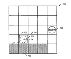
- FIG. 7 is a conceptual diagram showing the operation of the transport vehicle 1 according to the fourth embodiment of the present invention.
- FIG. 8 is a sequence diagram showing communication among the transport vehicle 1, the attachment 2, and the controller 3 according to the fourth embodiment of the present invention.
- FIG. 7 shows an example of a plan view of a work area 700 (for example, a space in a warehouse).
- the work area 700 is divided into a plurality of grids having a predetermined size (for example, a 1 m ⁇ 1 m square), and the movement instruction transmitted by the controller 3 includes the coordinate values of the grid as the coordinate values of the movement destination.
- the transport vehicles 701 and 702 shown in the work area 700 are both equivalent to the transport vehicle 1 in FIGS. 6 and 8.
- An attachment 706 attached to the transport vehicle 701 corresponds to the attachment 2 in FIGS. 6 and 8.
- the controller 3 can be installed at any place inside and outside the work area 700 as long as it can communicate with the transport vehicles 701 and 702 and the attachment 706.
- the transport vehicle 701 attaches the attachment 706 and performs the work instructed by the controller 3 in the work area 700
- the attachment 706 is a robot arm
- the instructed work is a work in which the transport vehicle 701 and the attachment 2 grab an article stored on a shelf 705 (shaded portion) and transport it to a predetermined position. is there.
- the transport vehicle 1 and the attachment 2 in FIG. 8 are, for example, the transport vehicle 701 and the attachment 706 (that is, a robot arm) in FIG.
- step S801 the attachment 2 receives sensor information of the mounted camera or the like and transmits it to the transport vehicle 1. At the same time, the attachment 2 transmits sensor information to the controller 3 and notifies if the movement of the coordinate position of the transport vehicle 1 is necessary.
- the measurement unit 602 measures the distance to the target object of the designated work, and the position determination unit 603 determines that the article is the attachment 2 (that is, the robot) It is determined whether the arm is within the operating range.
- the fine operation instruction unit 604 transmits the movement direction and the movement distance to the transport vehicle 1.
- the operation instruction unit 605 transmits sensor information and a notification that the position of the transport vehicle 1 is being finely adjusted to the controller 3.
- step S802 the transport vehicle 1 receives the information transmitted by the attachment 2 and returns a notification to the effect that it has been received.
- step S ⁇ b> 803 the transport vehicle 1 notifies the controller 3 that the movement for the adjustment operation according to the information from the fine operation instruction unit 604 is started based on the information on the movement direction and the movement distance sent from the attachment 2. .
- This notification includes information on the moving direction. For example, when the moving direction of the transport vehicle 701 in the grid 703 is the direction of the grid 704, information indicating that the grid 704 is the moving destination is notified.
- step S804 the transport vehicle 1 starts moving.
- step S805 the controller 3 receives a notification to start the adjustment operation from the transport vehicle 1 and restricts the entry of other transport vehicles. For example, as described above, when the transport vehicle 701 located on the grid 703 is moved in the direction of the grid 704 for the adjustment operation, there is a possibility that at least a part of the transport vehicle 701 may enter the grid 704. If the other vehicle (for example, the conveyance vehicle 702) is allowed to enter the grid 704, both may collide with each other. For this reason, the transport vehicle 702 is restricted from entering the grid 703 and the grid 704 when the transport vehicle 701 starts the adjustment operation.
- the other vehicle for example, the conveyance vehicle 702
- the controller 3 uses the current position of the transport vehicle 701 (the grid 703 in the above example) and a predetermined range in the moving direction (the grid in the above example) as the destination of the transport vehicle 702. 704) is not specified, and an instruction to prohibit entry into the grids 703 and 704 is transmitted to the transport vehicle 702.
- the control unit 608 of the transport vehicle 702 controls the movement of the transport vehicle 702 so as not to enter the designated grid.
- the transport vehicle 702 selects a route that does not include the grids 703 and 704 as the travel route from the current position to the destination designated by the travel instruction unit 610. Thereby, the collision between the transport vehicle 702 and the transport vehicle 701 is avoided.
- the controller 3 may select a route that does not include the grids 703 and 704 and notify the conveyance vehicle 702, and the conveyance vehicle 702 may move along the route. Even when there are a plurality of transport vehicles other than the transport vehicle 701, the same processing as described above is executed by each transport vehicle and the controller 3.
- step S806 the transport vehicle 1 transmits an operation result notification to the attachment 2.
- step S807 the attachment 2 receives this notification and performs the work instructed by the controller 3.
- step S808 when the work of the attachment 2 is completed, the attachment 2 transmits a work completion notification to the transport vehicle 1.
- step S809 the transport vehicle 1 receives the notification from the attachment 2, transmits an operation completion notification to the controller 3, and notifies the current position of the transport vehicle 1 together.
- step S810 the controller 3 receives the operation completion notification from the transport vehicle 1 and cancels the entry restriction of the other transport vehicle to a position other than the current position of the transport vehicle 1. If the position of the transport vehicle 701 after the adjustment operation is the grid 703, the entry restriction of the grid 704 that has been restricted to entry is cancelled.
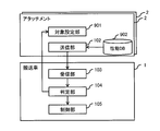
- FIG. 9 is a functional block diagram showing the configuration of the transport system according to the fifth embodiment of the present invention.
- FIG. 9 shows an example in which one transport vehicle 1 has two attachments 2 attached thereto, but actually three or more attachments 2 may be attached.
- Each attachment 2 includes a target setting unit 901 and a performance database (DB) 902 in addition to the transmission unit 102. Although omitted in FIG. 9, each attachment 2 may further include a measurement unit 101.
- the target setting unit 901 is a function realized by the processor 112 executing a program stored in the storage device 113.
- the performance DB 902 includes information regarding the performance of each attachment 2 and is stored in the storage device 113.
- the attachment 2 reads the performance of the attachment 2 from the performance DB 902 and notifies the transport vehicle 1 from the transmission unit 102.
- the performance of the attachment 2 is, for example, load resistance (upper limit of the weight of an article that can be grasped by the arm if it is a robot arm, upper limit of the weight of an article that can be mounted if it is a belt conveyor), but is not limited thereto. Absent.
- the transport vehicle 1 receives information from the attachment 2 at the receiving unit 103. Since the transport vehicle 1 is equipped with a plurality of attachments 2, it receives performance information from each of the attachments 2.
- the determination unit 104 obtains constraints on the plurality of attachments 2 based on the received performance information. For example, when the load resistance of one attachment 2 is 10 kg and the load resistance of the other attachment 2 is 5 kg, assuming that these two attachments work together, the determination unit 104 has two Load capacity is set at 5kg for both attachments. This is a case of setting to the safe side.
- both of the two attachments 2 are robot arms, as long as each handles an article independently, an article having a weight that does not exceed the respective load resistance may be handled.
- the determination unit 104 determines that the same performance value as that of the lower one is set for the robot arms so that the robot arms with lower load resistance can withstand all loads.
- load resistance is given as an example of performance, but the same applies to other performances, and the same applies when three or more attachments 2 are mounted. That is, the same value as the lowest performance among those performances is set for all attached attachments 2.
- the determination unit 104 notifies the determined load resistance to the target setting unit 901 of each attachment 2 attached to the transport vehicle 1.
- the target setting unit 901 sets an article that is a work target. For example, when the load resistance is set to 5 kg, if the work target article notified from the controller 3 exceeds 5 kg, the controller 3 is notified that it is out of the work target.
- the weight of the article may be measured with a measuring instrument as the sensor 111 in the attachment 2, or the article printed on the article when a camera or the like is installed as the sensor 111. May be obtained by recognizing the weight information of the camera with the camera or the like.
- the receiving unit 103, the determination unit 104, and the control unit 105 of the transport vehicle 1 of the present embodiment further have the functions described in the first embodiment.
- the transport vehicle 1 of the present embodiment further includes a determination reference DB 106.
- each attachment 2 of the present embodiment further includes the measurement unit 101 described in the first embodiment.
- FIG. 10 is an explanatory diagram of the center of gravity when one or more attachments 2 are mounted on the transport vehicle 1 according to the fifth embodiment of the present invention.
- FIG. 10 are both equivalent to the transport vehicle 1 shown in FIG. 9.
- the transport vehicles 1001 and 1002 shown in FIG. On the other hand, robot arms 1003 and 1004 shown in FIG. 10 are both examples of the attachment 2 shown in FIG.
- the transport vehicle 1001 is equipped with one robot arm 1003.
- the center of gravity of the entire moving body in which the transport vehicle 1001 and the robot arm 1003 are integrated can be expressed by the center of gravity A.
- the center of gravity of the entire moving body in which the transport vehicle 1002 and the robot arms 1003 and 1004 are integrated can be expressed by the center of gravity B.
- the determination unit 104 of the transport vehicle 1001 determines the position of the center of gravity of the entire moving body including the transport vehicle 1001 and the robot arm 1003, and the load resistance of the robot arm 1003 is 10 kg. It is determined that it can be lifted.
- the determination unit 104 of the transport vehicle 1002 obtains the position of the center of gravity of the entire moving body including the transport vehicle 1002 and the robot arms 1003 and 1004 from the positions of the robot arms 1003 and 1004, and the transport vehicle when a 10 kg article is lifted.
- the slope of 1002 is obtained.
- the transport vehicle 1002 may roll over, and thus a load resistance of the robot arm 1003 is set to a value smaller than 10 kg so that the inclination is equal to or less than the threshold value.
- the value to be set is calculated by the determination unit 104.
- a predetermined relationship between the center of gravity and the load may be extracted from the determination criterion DB 106 and used.
- the performance DB 902 of each attachment 2 adds the weight of each attachment 2 and the gravity center position (particularly to the attachment mounting portion 304 of the transport vehicle 1 to which each attachment 2 is mounted) in addition to the performance of each attachment 2.
- the information may include information indicating the position of the center of gravity) and the position of the part on which the article is mounted (for example, the position of the hand portion of the robot arm), and the transmission unit 102 may transmit the information to the transport vehicle 1.
- This information may include information indicating the relationship between the shape of the attachment 2, the position of the center of gravity, and the position of the hand unit in the case of the attachment 2 that is deformed with the movement of the position of the center of gravity, such as a robot arm.
- the transport vehicle 1 information such as the own weight of the transport vehicle 1, the position of the center of gravity, and the position of the ground point (for example, the position of the wheel) is stored in the storage device 109. Based on the information transmitted from the attachment 2, the center of gravity position of the entire moving body including the transport vehicle 1 and one or more attachments 2 attached thereto is calculated, and the calculated result and the attachment 2 are installed. Further, based on the weight of the article, the inclination when the article is installed on each attachment 2 can be calculated. Since the inclination can be calculated by any known method, a detailed description of the calculation method is omitted.
- the determination unit 104 can set the load resistance of each attachment 2 so that the calculated inclination does not exceed a predetermined threshold stored as a determination criterion in the determination criterion DB 106. Furthermore, the determination unit 104 may constrain the performance of the transport vehicle 1 when the result of calculating the center of gravity satisfies a predetermined condition stored as a determination criterion in the determination criterion DB 106. For example, the determination unit 104 determines that the calculated inclination exceeds a predetermined threshold (may be a value different from the threshold for setting the load resistance described above), or the calculated position of the center of gravity is within a predetermined range. If it is within the range, the moving speed may be restricted to a predetermined value or less.
- a predetermined threshold may be a value different from the threshold for setting the load resistance described above
- the determination criterion DB 106 includes a determination criterion for determining whether or not to perform performance restriction based on the calculation result of the center of gravity for each attribute (for example, type) of the attachment, and the determination unit 104 determines the above-mentioned according to the determination criterion Make a decision.
- the transport vehicle 1 is equipped with a plurality of attachments 2
- the transport vehicle 1 is equipped with one attachment 2
- the transport vehicle 1 is equipped with one attachment 2
- the movement speed or the like of the transport vehicle 1 may be constrained based on the inclination when the vehicle is installed. This makes it possible to prevent the transport vehicle 1 from overturning, particularly when the attachment 2 that is deformed with the movement of the center of gravity is mounted like a robot arm.
- the present invention is not limited to the above-described embodiments, and includes various modifications.
- each of the above-described embodiments has been described in detail for easy understanding of the present invention, and is not necessarily limited to one having all the configurations described.
- a part of the configuration of a certain embodiment can be replaced with the configuration of another embodiment, and the configuration of another embodiment can be added to the configuration of a certain embodiment.
- the restriction on the movement speed and the restriction on the movement route are shown as examples of the restriction on the movement of the transport vehicle 1.
- the acceleration of the transport vehicle 1 may be constrained instead of (or in addition to) the travel speed in order to prevent an article from dropping or the transport vehicle 1 from rolling over.
- the type of the attachment 2 is a belt conveyor and is connected to a belt conveyor mounted on one or more other transport vehicles 1 to form one long belt conveyor, the other adjacent transport vehicles 1
- the movement of the transport vehicle 1 may be restricted so as to keep the distance to the constant.
- the attachment 2 has a distance measuring device that measures the distance to the adjacent transport vehicle 1 as the sensor 111, and the determination reference DB 106 is a predetermined distance between the adjacent transport vehicle 1 as a determination reference corresponding to the belt conveyor.
- the determination unit 104 determines that the movement of the transport vehicle 1 needs to be restricted based on the determination criterion DB 106, and the control unit 105 according to the determination. May control the movement of the transport vehicle.
- the attachment 2 can appropriately exhibit the functions of a belt conveyor and the like.
- the travel distance depends on the weight of the article or the attachment 2 itself in order to prevent the transport vehicle 1 from being stopped due to battery consumption. May be constrained.
- the determination criterion DB 106 includes information that associates the weight of the attachment 2 itself, the weight of the article, and the movement distance, and the determination unit 104 determines that the movement distance of the transport vehicle 1 is restricted based on the information from the reception unit 103. May be.
- the determination criterion DB 106 includes information indicating that the movement distance is restricted to a predetermined value or less regardless of the weight of the article when the attachment 2 is a lifter dedicated to heavy objects.
- the movement distance of the transport vehicle 1 is restricted to a predetermined value or less when a lifter dedicated to heavy objects is attached. Thereby, the unintentional stop of the transport vehicle 1 due to battery consumption can be prevented.
- the type of the attachment 2 is cited as an example of the attribute of the attachment 2.
- the determination criterion DB 106 includes a determination criterion for each attribute other than the type of the attachment 2, and the determination unit 104 determines the determination criterion. Accordingly, the movement of the transport vehicle 1 may be restricted. Specifically, for example, as shown in FIG. 4, when there is a limit on the size of an object that can be passed, the size of an article that can be set and passed through the attachment 2 varies depending on the size of the attachment 2 itself. For this reason, the criterion DB 106 may include information that associates the size of each attachment 2 with the size of an article that can be installed and passed. Alternatively, when the movement distance of the transport vehicle 1 is restricted due to battery consumption as described above, information that associates the weight of the attachment 2 with the weight of the article and the restriction on the movement distance may be included. .
- the measurement unit 101 measures the weight or size of the article, and the transmission unit 102 transmits the result to the transport vehicle 1.
- the attachment 2 is the weight or size of the article. Any information may be transmitted as long as the information can be used to specify the attribute. For example, when a character or barcode indicating the weight of the article is displayed on the surface of the article, the measurement unit 101 reads the character and the like, and the transmission unit 102 transmits the weight of the article obtained therefrom. May be. Alternatively, characters or barcodes including identification information of the article are displayed on the surface of the article, and the attachment 2 or the carriage 1 holds information that associates the identification information of the article with the weight of the article. If it is, the measurement unit 101 may read the identification information, and the attachment 2 or the transport vehicle 1 may specify the weight of the article based on the identification information.
- each function or the like of the transport system may be realized by hardware by designing a part or all of the functions, for example, with an integrated circuit.
- Each function of the processing unit may be realized by software by the processor interpreting and executing a program that realizes each function.
- Information such as programs, tables, and files that realize each function is stored in a memory, a hard disk, a recording device such as SSD (Solid State Drive), or a computer-readable non-readable data such as an IC card, SD card, DVD (Digital Versatile Disc) It can be stored in a temporary data recording medium.
Landscapes
- Engineering & Computer Science (AREA)
- Radar, Positioning & Navigation (AREA)
- Aviation & Aerospace Engineering (AREA)
- Remote Sensing (AREA)
- Physics & Mathematics (AREA)
- General Physics & Mathematics (AREA)
- Automation & Control Theory (AREA)
- Mechanical Engineering (AREA)
- Control Of Position, Course, Altitude, Or Attitude Of Moving Bodies (AREA)
Abstract
Priority Applications (4)
| Application Number | Priority Date | Filing Date | Title |
|---|---|---|---|
| US15/309,577 US20170183155A1 (en) | 2014-12-26 | 2014-12-26 | Conveying vehicle and conveying system |
| PCT/JP2014/084533 WO2016103452A1 (fr) | 2014-12-26 | 2014-12-26 | Véhicule de transport et système de transport |
| CN201480079522.3A CN107533332B (zh) | 2014-12-26 | 2014-12-26 | 运输车及运输系统 |
| JP2016565805A JP6283753B2 (ja) | 2014-12-26 | 2014-12-26 | 搬送車及び搬送システム |
Applications Claiming Priority (1)
| Application Number | Priority Date | Filing Date | Title |
|---|---|---|---|
| PCT/JP2014/084533 WO2016103452A1 (fr) | 2014-12-26 | 2014-12-26 | Véhicule de transport et système de transport |
Publications (1)
| Publication Number | Publication Date |
|---|---|
| WO2016103452A1 true WO2016103452A1 (fr) | 2016-06-30 |
Family
ID=56149540
Family Applications (1)
| Application Number | Title | Priority Date | Filing Date |
|---|---|---|---|
| PCT/JP2014/084533 WO2016103452A1 (fr) | 2014-12-26 | 2014-12-26 | Véhicule de transport et système de transport |
Country Status (4)
| Country | Link |
|---|---|
| US (1) | US20170183155A1 (fr) |
| JP (1) | JP6283753B2 (fr) |
| CN (1) | CN107533332B (fr) |
| WO (1) | WO2016103452A1 (fr) |
Cited By (6)
| Publication number | Priority date | Publication date | Assignee | Title |
|---|---|---|---|---|
| CN106020198A (zh) * | 2016-07-06 | 2016-10-12 | 尚艳燕 | 一种体感车载物的方法和体感车 |
| CN106444747A (zh) * | 2016-09-05 | 2017-02-22 | 尚艳燕 | 一种平衡车载物的方法和平衡车 |
| JP2018179849A (ja) * | 2017-04-18 | 2018-11-15 | 株式会社ミツトヨ | 駆動ステージ装置の駆動制御方法 |
| JP2019091261A (ja) * | 2017-11-15 | 2019-06-13 | ヤマハ発動機株式会社 | 資材の搬送システム |
| JP2019117431A (ja) * | 2017-12-26 | 2019-07-18 | トヨタ自動車株式会社 | 自律移動ロボット |
| JP2020038631A (ja) * | 2018-08-30 | 2020-03-12 | キヤノン株式会社 | 情報処理装置、情報処理方法、プログラムおよびシステム |
Families Citing this family (8)
| Publication number | Priority date | Publication date | Assignee | Title |
|---|---|---|---|---|
| AU2017306566B2 (en) | 2016-08-04 | 2021-02-18 | Opex Corporation | Automated storage and retrieval system with detector for detecting items extending beyond dimensional threshold |
| AU2019290096B2 (en) * | 2018-06-21 | 2022-12-01 | Beijing Geekplus Technology Co., Ltd. | Robot scheduling and robot path control method, server and storage medium |
| US11573574B2 (en) * | 2018-08-30 | 2023-02-07 | Canon Kabushiki Kaisha | Information processing apparatus, information processing method, information processing system, and storage medium |
| CN108897329A (zh) * | 2018-09-29 | 2018-11-27 | 苏州博众机器人有限公司 | 一种机器人速度控制方法、装置、设备和存储介质 |
| JP6678839B1 (ja) * | 2019-03-26 | 2020-04-08 | 楽天株式会社 | 荷受け仕分け装置及び荷受け仕分け方法 |
| JP7229128B2 (ja) * | 2019-09-02 | 2023-02-27 | 本田技研工業株式会社 | 車両制御装置 |
| JP7388241B2 (ja) * | 2020-02-28 | 2023-11-29 | オムロン株式会社 | 制御装置及び搬送システム |
| EP4325042A1 (fr) * | 2022-08-16 | 2024-02-21 | Dematic GmbH | Système d'exécution de commandes doté d'une zone d'exécution de commandes au sol comprenant au moins une station de préparation de commandes |
Citations (3)
| Publication number | Priority date | Publication date | Assignee | Title |
|---|---|---|---|---|
| JPS63261404A (ja) * | 1987-04-17 | 1988-10-28 | Mitsubishi Electric Corp | 自動搬送走行制御装置 |
| JP2011216007A (ja) * | 2010-04-01 | 2011-10-27 | Gen Inc | 搬送台車システム |
| JP2012058792A (ja) * | 2010-09-03 | 2012-03-22 | Toyota Motor Corp | 搬送装置 |
Family Cites Families (6)
| Publication number | Priority date | Publication date | Assignee | Title |
|---|---|---|---|---|
| JP2001216007A (ja) * | 2000-02-04 | 2001-08-10 | Hitachi Eng Co Ltd | ラダーシーケンスプログラム仕様書自動生成支援システム |
| US7991521B2 (en) * | 2006-02-01 | 2011-08-02 | Jervis B. Webb Company | Variable path automated guided vehicle |
| CN101379368A (zh) * | 2006-02-01 | 2009-03-04 | 杰维斯·B·韦布国际公司 | 可变路径自动导引车辆 |
| JP4475247B2 (ja) * | 2006-03-27 | 2010-06-09 | 株式会社豊田自動織機 | 走行車の走行制御システム |
| BR112013029217A2 (pt) * | 2011-05-13 | 2017-01-31 | Beckman Coulter Inc | sistema e método incluindo um elemento de transporte de produtos de laboratório |
| EP2707725B1 (fr) * | 2011-05-13 | 2018-07-11 | Beckman Coulter, Inc. | Élément de transport de produits de laboratoire et agencement pour trajet |
-
2014
- 2014-12-26 US US15/309,577 patent/US20170183155A1/en not_active Abandoned
- 2014-12-26 JP JP2016565805A patent/JP6283753B2/ja not_active Expired - Fee Related
- 2014-12-26 CN CN201480079522.3A patent/CN107533332B/zh active Active
- 2014-12-26 WO PCT/JP2014/084533 patent/WO2016103452A1/fr active Application Filing
Patent Citations (3)
| Publication number | Priority date | Publication date | Assignee | Title |
|---|---|---|---|---|
| JPS63261404A (ja) * | 1987-04-17 | 1988-10-28 | Mitsubishi Electric Corp | 自動搬送走行制御装置 |
| JP2011216007A (ja) * | 2010-04-01 | 2011-10-27 | Gen Inc | 搬送台車システム |
| JP2012058792A (ja) * | 2010-09-03 | 2012-03-22 | Toyota Motor Corp | 搬送装置 |
Cited By (9)
| Publication number | Priority date | Publication date | Assignee | Title |
|---|---|---|---|---|
| CN106020198A (zh) * | 2016-07-06 | 2016-10-12 | 尚艳燕 | 一种体感车载物的方法和体感车 |
| CN106444747A (zh) * | 2016-09-05 | 2017-02-22 | 尚艳燕 | 一种平衡车载物的方法和平衡车 |
| JP2018179849A (ja) * | 2017-04-18 | 2018-11-15 | 株式会社ミツトヨ | 駆動ステージ装置の駆動制御方法 |
| JP2019091261A (ja) * | 2017-11-15 | 2019-06-13 | ヤマハ発動機株式会社 | 資材の搬送システム |
| JP7260956B2 (ja) | 2017-11-15 | 2023-04-19 | ヤマハ発動機株式会社 | 資材の搬送システム |
| JP2019117431A (ja) * | 2017-12-26 | 2019-07-18 | トヨタ自動車株式会社 | 自律移動ロボット |
| JP7069703B2 (ja) | 2017-12-26 | 2022-05-18 | トヨタ自動車株式会社 | 自律移動ロボット |
| JP2020038631A (ja) * | 2018-08-30 | 2020-03-12 | キヤノン株式会社 | 情報処理装置、情報処理方法、プログラムおよびシステム |
| JP7479799B2 (ja) | 2018-08-30 | 2024-05-09 | キヤノン株式会社 | 情報処理装置、情報処理方法、プログラムおよびシステム |
Also Published As
| Publication number | Publication date |
|---|---|
| JP6283753B2 (ja) | 2018-02-28 |
| US20170183155A1 (en) | 2017-06-29 |
| CN107533332A (zh) | 2018-01-02 |
| JPWO2016103452A1 (ja) | 2017-08-24 |
| CN107533332B (zh) | 2021-07-09 |
Similar Documents
| Publication | Publication Date | Title |
|---|---|---|
| JP6283753B2 (ja) | 搬送車及び搬送システム | |
| US10983512B2 (en) | Automated creel systems and methods for using same | |
| US11724882B2 (en) | Controlling automated pallet movers | |
| JP5982729B2 (ja) | 搬送管理装置、搬送システム、および、搬送管理プログラム | |
| US20170182664A1 (en) | Adjusting Robot Safety Limits Based On Network Connectivity | |
| US20190177086A1 (en) | A picking system having a transport robot for moving underneath individualshelves and transporting vehicle | |
| JP7199003B2 (ja) | 搬送装置、受信機能付き搬送装置、搬送システム、上位システム、搬送装置の制御方法、及びプログラム | |
| WO2020220950A1 (fr) | Système de transport d'articles | |
| JP5884594B2 (ja) | 自動倉庫 | |
| CN207903351U (zh) | 一种自主控制平衡的物流机器人 | |
| KR20180042975A (ko) | 적재물 무게중심 위치 감지를 통해 가감속 제어가 가능한 이동 유닛 | |
| KR101462527B1 (ko) | 무인운반차량 | |
| JP6275899B2 (ja) | タイヤ式門形クレーン及びその制御方法 | |
| JP6113546B2 (ja) | コンテナターミナル | |
| WO2021177135A1 (fr) | Système d'entrepôt automatisé et procédé de commande pour système d'entrepôt automatisé | |
| EP3771955B1 (fr) | Procédé et système de commande d'un robot mobile autonome utilisant une mesure de la charge utile | |
| US20220397911A1 (en) | Transport device, control method, and recording medium on which control program is recorded | |
| JP7401285B2 (ja) | 自動倉庫システム | |
| JP6764137B2 (ja) | 管理方法、管理装置、プログラム | |
| US20220402129A1 (en) | Transport control device, transport control method, and recording medium on which transport control program is recorded | |
| JP6284212B1 (ja) | 荷役作業割当システム及び方法 | |
| JP5796300B2 (ja) | 自動倉庫 | |
| US20230381822A1 (en) | Information processing device, information processing method, computer-readable storage medium, and system | |
| JP7206811B2 (ja) | 搬送システム | |
| JP2014006832A (ja) | 搬送システム |
Legal Events
| Date | Code | Title | Description |
|---|---|---|---|
| 121 | Ep: the epo has been informed by wipo that ep was designated in this application |
Ref document number: 14909056 Country of ref document: EP Kind code of ref document: A1 |
|
| WWE | Wipo information: entry into national phase |
Ref document number: 15309577 Country of ref document: US |
|
| ENP | Entry into the national phase |
Ref document number: 2016565805 Country of ref document: JP Kind code of ref document: A |
|
| NENP | Non-entry into the national phase |
Ref country code: DE |
|
| 122 | Ep: pct application non-entry in european phase |
Ref document number: 14909056 Country of ref document: EP Kind code of ref document: A1 |