WO2016098592A1 - 符号化装置、符号化方法、復号装置、復号方法、プログラム、および無線通信システム - Google Patents
符号化装置、符号化方法、復号装置、復号方法、プログラム、および無線通信システム Download PDFInfo
- Publication number
- WO2016098592A1 WO2016098592A1 PCT/JP2015/083896 JP2015083896W WO2016098592A1 WO 2016098592 A1 WO2016098592 A1 WO 2016098592A1 JP 2015083896 W JP2015083896 W JP 2015083896W WO 2016098592 A1 WO2016098592 A1 WO 2016098592A1
- Authority
- WO
- WIPO (PCT)
- Prior art keywords
- modulation
- information
- encoding
- coding
- header
- Prior art date
- Legal status (The legal status is an assumption and is not a legal conclusion. Google has not performed a legal analysis and makes no representation as to the accuracy of the status listed.)
- Ceased
Links
Images


Classifications
-
- H—ELECTRICITY
- H04—ELECTRIC COMMUNICATION TECHNIQUE
- H04W—WIRELESS COMMUNICATION NETWORKS
- H04W28/00—Network traffic management; Network resource management
- H04W28/02—Traffic management, e.g. flow control or congestion control
- H04W28/06—Optimizing the usage of the radio link, e.g. header compression, information sizing, discarding information
-
- H—ELECTRICITY
- H04—ELECTRIC COMMUNICATION TECHNIQUE
- H04L—TRANSMISSION OF DIGITAL INFORMATION, e.g. TELEGRAPHIC COMMUNICATION
- H04L1/00—Arrangements for detecting or preventing errors in the information received
- H04L1/0001—Systems modifying transmission characteristics according to link quality, e.g. power backoff
- H04L1/0002—Systems modifying transmission characteristics according to link quality, e.g. power backoff by adapting the transmission rate
- H04L1/0003—Systems modifying transmission characteristics according to link quality, e.g. power backoff by adapting the transmission rate by switching between different modulation schemes
-
- H—ELECTRICITY
- H04—ELECTRIC COMMUNICATION TECHNIQUE
- H04L—TRANSMISSION OF DIGITAL INFORMATION, e.g. TELEGRAPHIC COMMUNICATION
- H04L1/00—Arrangements for detecting or preventing errors in the information received
- H04L1/004—Arrangements for detecting or preventing errors in the information received by using forward error control
- H04L1/0056—Systems characterized by the type of code used
- H04L1/007—Unequal error protection
-
- H—ELECTRICITY
- H04—ELECTRIC COMMUNICATION TECHNIQUE
- H04L—TRANSMISSION OF DIGITAL INFORMATION, e.g. TELEGRAPHIC COMMUNICATION
- H04L1/00—Arrangements for detecting or preventing errors in the information received
- H04L1/004—Arrangements for detecting or preventing errors in the information received by using forward error control
- H04L1/0072—Error control for data other than payload data, e.g. control data
-
- H—ELECTRICITY
- H04—ELECTRIC COMMUNICATION TECHNIQUE
- H04L—TRANSMISSION OF DIGITAL INFORMATION, e.g. TELEGRAPHIC COMMUNICATION
- H04L1/00—Arrangements for detecting or preventing errors in the information received
- H04L1/004—Arrangements for detecting or preventing errors in the information received by using forward error control
- H04L1/0075—Transmission of coding parameters to receiver
-
- H—ELECTRICITY
- H04—ELECTRIC COMMUNICATION TECHNIQUE
- H04L—TRANSMISSION OF DIGITAL INFORMATION, e.g. TELEGRAPHIC COMMUNICATION
- H04L1/00—Arrangements for detecting or preventing errors in the information received
- H04L1/0078—Avoidance of errors by organising the transmitted data in a format specifically designed to deal with errors, e.g. location
- H04L1/0086—Unequal error protection
- H04L1/0088—Unequal error protection in control part
-
- H—ELECTRICITY
- H04—ELECTRIC COMMUNICATION TECHNIQUE
- H04L—TRANSMISSION OF DIGITAL INFORMATION, e.g. TELEGRAPHIC COMMUNICATION
- H04L5/00—Arrangements affording multiple use of the transmission path
- H04L5/003—Arrangements for allocating sub-channels of the transmission path
- H04L5/0044—Allocation of payload; Allocation of data channels, e.g. PDSCH or PUSCH
-
- H—ELECTRICITY
- H04—ELECTRIC COMMUNICATION TECHNIQUE
- H04L—TRANSMISSION OF DIGITAL INFORMATION, e.g. TELEGRAPHIC COMMUNICATION
- H04L1/00—Arrangements for detecting or preventing errors in the information received
- H04L1/0001—Systems modifying transmission characteristics according to link quality, e.g. power backoff
- H04L1/0009—Systems modifying transmission characteristics according to link quality, e.g. power backoff by adapting the channel coding
Definitions
- the present technology relates to an encoding device, an encoding method, a decoding device, a decoding method, a program, and a wireless communication system, and in particular, encoding capable of efficiently performing frame transmission according to a transmission path condition.
- the present invention relates to a device, an encoding method, a decoding device, a decoding method, a program, and a wireless communication system.
- Data transmission / reception in a wireless communication system may be performed using frames.
- one frame is composed of a preamble, a header (physical layer header), and a payload.
- the preamble is configured by repeating a known signal sequence used for frame detection. Information necessary for demodulating and decoding the payload is stored in the header. User data to be transmitted is stored in the payload.
- the transmission apparatus uses a method having the same performance as the method with the highest demodulation / decoding performance among the modulation method and the coding method applied to the payload, or a method having higher performance. Used to encode and modulate the header.
- the transmitting apparatus selects a modulation scheme and a coding scheme according to the quality of the transmission path from among a plurality of schemes, and performs encoding and modulation of the payload using the selected scheme.
- the transmission apparatus performs encoding and modulation using one predetermined method.
- Patent Document 1 discloses a technique for storing information related to a header modulation scheme, encoding scheme, and the like in a physical layer header optimization field provided in a preamble. As a result, a method according to the quality of the transmission path can be used as the header modulation method and coding method, but the transmission efficiency is reduced by providing the header optimization field.
- the present technology has been made in view of such a situation, and makes it possible to efficiently transmit a frame according to the state of the transmission path.
- An encoding device includes a payload processing unit that encodes and modulates transmission data stored in a payload, and at least one of encoding and modulation for storage information stored in a header And encoding and modulation of modulation encoding information representing at least one of encoding and modulation schemes for the transmission data in a predetermined scheme, and encoding and modulation of the storage information
- a header processing unit that performs in a method represented by encoding information, and a header that includes a first area that stores the modulation and coding information and a second area that stores the storage information, and is added to the payload
- a transmission unit that transmits the frame to be transmitted.
- a decoding device includes at least one of encoding and modulation for storage information stored in a header and at least one of encoding and modulation for transmission data.
- a receiving unit that receives a frame configured by adding the header composed of a first area storing modulation coding information to be expressed and a second area storing the storage information to a payload storing the transmission data And demodulation of the modulation and coding information and decoding of the modulation and coding information after demodulation by a predetermined method, and decoding of the storage information and decoding of the storage information after demodulation and decoding
- a header processing unit that performs the method represented by the acquired modulation and coding information, and the modulation and coding information acquired by decoding and demodulation and decoding of the transmission data, or the modulation and coding information and And a payload processing unit which performs in the manner represented by the stored information.
- transmission data stored in a payload is encoded and modulated, and at least one of encoding and modulation for storage information stored in a header, and the transmission data Encoding and modulation of modulation encoding information representing at least one of encoding and modulation are performed by a predetermined method.
- the storage information is encoded and modulated by a method represented by the modulation encoding information, and a first area for storing the modulation encoding information and a second area for storing the storage information;
- the frame configured by adding the header consisting of: to the payload is transmitted.
- modulation representing at least one of encoding and modulation for storage information stored in a header and at least one of encoding and modulation for transmission data
- a frame configured by adding the header composed of a first area for storing encoded information and a second area for storing the stored information to a payload for storing the transmission data is received, and the modulation code
- the demodulated information is demodulated and the modulation and coding information after demodulation is decoded by a predetermined method.
- demodulation of the stored information and decoding of the stored information after demodulation are performed by a method represented by the modulation and coding information obtained by decoding, and demodulation and decoding of the transmission data are performed by decoding The modulation coding information acquired in this way, or the method represented by the modulation coding information and the storage information.
- FIG. 6 is a block diagram illustrating a configuration example of a header encoding / modulation circuit of FIG. 5. It is a block diagram which shows the structural example of a receiver. It is a block diagram which shows the structural example of the header demodulation and decoding circuit of FIG. It is a flowchart explaining the transmission process of a transmitter.
- FIG. 10 is a flowchart for describing header encoding / modulation processing performed in step S2 of FIG. 9. It is a flowchart explaining the reception process of a receiver. It is a flowchart explaining the header demodulation and decoding process performed in step S39 of FIG. It is a figure which shows the other structural example of a radio
- FIG. 1 is a diagram illustrating a configuration example of a wireless communication system according to an embodiment of the present technology.
- the playback device 1 includes a playback device 1, a transmission device 2, a reception device 3, and a display device 4.
- the playback device 1 and the transmission device 2, and the reception device 3 and the display device 4 are connected to each other through a cable of a predetermined standard such as an HDMI (registered trademark) (High Definition Multimedia Interface) cable.
- the playback device 1 and the transmission device 2, and the reception device 3 and the display device 4 may be connected via wireless communication.
- the playback device 1 is a player for content such as video and audio.
- the playback device 1 outputs AV (Audio Visual) data obtained by playback to the transmission device 2.
- AV Audio Visual
- Data other than AV data may be output to the transmission device 2 as data to be transmitted.
- the transmission device 2 performs processing such as encoding processing and modulation processing on the AV data transmitted from the reproduction device 1.
- the transmission device 2 functions as an encoding device and a modulation device.
- the transmitting apparatus 2 divides AV data obtained by performing various processes into predetermined units, stores the AV data in a payload, and generates a frame.
- the transmission device 2 transmits each frame to the reception device 3 by wireless communication using a predetermined frequency band such as a 60 GHz band.
- the receiving device 3 receives the signal transmitted from the transmitting device 2, and performs processing such as demodulation processing and decoding processing on the received signal.
- the receiving device 3 functions as a demodulating device and a decoding device.
- the transmission device 2 generates AV data by extracting data stored in the payload of each frame obtained by performing various processes, and outputs the AV data to the display device 4.
- the display device 4 is a device having a display unit such as an LCD or an organic EL display.
- the display device 4 receives the AV data transmitted from the receiving device 3 and displays video on a display or outputs audio from a speaker.
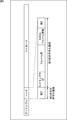
- FIG. 2 is a diagram illustrating an example of a frame format used for data transmission / reception in the wireless communication system of FIG.
- One frame consists of a preamble, a header (physical layer header), and a payload.
- the preamble is configured by repeating a known signal sequence used for frame detection.
- the known signal sequence includes a unique signal sequence used for frame synchronization and a signal sequence used for evaluating transmission path characteristics.
- the header stores information essential for demodulating and decoding the payload.
- AV data that is user data to be transmitted is stored in the payload.
- the header includes MCS (Modulation and Coding Scheme), scrambler ID, frame length, and HCS (Header Check Sequence). Between the frame length and the HCS, other frame information essential for demodulating and decoding the payload is included as appropriate.
- MCS Modulation and Coding Scheme
- HCS Header Check Sequence
- MCS is information on the header modulation method and coding method, and the payload modulation method and coding method.
- the MCS which is modulation and coding information, represents not only the payload modulation method and coding method, but also the header modulation method and coding method.
- the receiving device 3 acquires the MCS by performing demodulation and decoding by a predetermined method after detecting the head of the header, and performs demodulation and decoding of information after the MCS based on the acquired MCS.
- the scrambler ID, frame length, frame information, and HCS areas are MCS-dependent coding areas in which the modulation scheme and the coding scheme depend on MCS.
- the MCS area is an MCS-independent coding area in which the modulation scheme and the coding scheme do not depend on the contents of the MCS. Specific examples of MCS will be described later.
- the scrambler ID is information such as a scramble initial value used when scrambling the payload or the header after the scrambler ID.
- the scramble is performed by the transmission apparatus 2 in order to prevent the transmission spectrum from being biased. When a fixed signal sequence pattern is used, the transmission spectrum may be biased. Based on the scrambler ID, the receiving device 3 unscrambles the scramble applied to the payload or the like.
- the frame length is information on the length of the payload.
- the receiving device 3 ends the demodulation and decoding of the payload based on the frame length.
- HCS is a parity word used for header error detection.
- the receiving device 3 performs header error detection based on the HCS, and determines whether or not to perform demodulation and decoding of the payload.
- FIG. 3 is a diagram showing an example of the meaning of MCS.
- the modulation method of MCS is BPSK (Binary Phase Shift Keying).
- the MCS encoding scheme is a spreading encoding scheme with a spreading factor of 24.
- the MCS modulation method and encoding method are both fixed methods and are determined in advance.
- the MCS-independent coding region of the header is a region where the spreading rate of spreading coding is fixed.
- the MCS-dependent coding region is a region where the spreading factor of spreading coding is variable.
- the MCS-independent coding region is referred to as a fixed spreading region, and the MCS-dependent coding region is referred to as a variable spreading region.
- the encoding method of information stored in the header is spread encoding.
- MCS represents the modulation method of the payload and the coding rate of the error correction coding of the payload.
- MCS represents the modulation scheme of the entire header including MCS, and the spreading rate of each of the fixed spreading area and the variable spreading area.
- the payload is modulated by BPSK and subjected to error correction coding at a coding rate of 11/15.
- the header is modulated by BPSK and is subjected to spreading coding with a spreading factor of 24.
- the payload is modulated by BPSK and subjected to error correction coding at a coding rate of 14/15.
- the header is modulated by BPSK, and is subjected to spreading coding with a spreading factor of 24 times for information in the fixed spreading region and a spreading factor of 16 times for information in the variable spreading region.
- the payload is modulated by QPSK and subjected to error correction coding at a coding rate of 11/15.
- the header is modulated by BPSK, and is subjected to spreading coding with a spreading factor of 24 times for information in the fixed spreading region and a spreading factor of 16 times for information in the variable spreading region.
- the payload is modulated by QPSK and subjected to error correction coding with a coding rate of 14/15.
- the header is modulated by BPSK, and is subjected to spreading coding with a spreading factor of 24 times for information in the fixed spreading region and a spreading factor of 8 times for information in the variable spreading region.
- the payload is modulated with 16QAM and error correction coding with a coding rate of 11/15 is performed. Further, the header is modulated by BPSK and is subjected to spreading coding with a spreading factor of 24 times for information in the fixed spreading region and a spreading factor of 4 for information in the variable spreading region.
- the payload is modulated with 16QAM and error correction coding with a coding rate of 14/15 is performed. Further, the header is modulated by BPSK and is subjected to spreading coding with a spreading factor of 24 times for information in the fixed spreading region and a spreading factor of 2 for information in the variable spreading region.
- the MCS arranged at the head of the header represents the modulation scheme of the payload and the coding rate of the error correction coding, and also represents the modulation scheme of the header itself and the spreading rate of the spreading coding.
- Information representing the meaning of MCS as shown in FIG. 3 is stored in advance in the memories of the transmission device 2 and the reception device 3, respectively.
- demodulation and decoding of the payload will not be performed correctly.
- a scheme having demodulation / decoding performance equivalent to that of the payload modulation and coding scheme or a scheme having higher demodulation / decoding performance is selected.
- Demodulation / decoding performance is the total performance of demodulation and decoding.
- the MCS modulation and coding scheme a scheme having the highest demodulation / decoding performance is selected from among a plurality of schemes used for modulation and coding of information after MCS.
- BPSK is used for header modulation, but other modulation methods such as QPSK and 16QAM may be used. Also, although the entire header is modulated with the same BPSK, different modulation schemes may be used for MCS modulation and subsequent information modulation. For the MCS modulation, a method with the highest total performance of demodulation and decoding is selected from among a plurality of methods used for modulation and encoding of subsequent information.
- the spreading factor of the spread coding for the fixed spreading region is fixed at 24 times, any other spreading factor may be used as long as the spreading factor provides a performance equal to or higher than the total demodulation and decoding performance for the variable spreading region.
- the combination of modulation scheme and encoding scheme represented by MCS is not limited to that shown in FIG.
- the header modulation scheme when the MCS number is 4 is QPSK
- the spreading rate of the spread coding for the fixed spreading region is 12 times
- the spreading rate of the spreading coding for the variable spreading region is doubled. It is possible.
- the header modulation scheme when the MCS number is 5 may be QPSK
- the spreading factor of the spreading coding for the fixed spreading region may be 12 times
- the spreading factor of the spreading coding for the variable spreading region may be 1 time.
- a spreading factor of spreading encoding of 1 means that no encoding is performed.
- the MCS numbers 0 to 5 are used to represent combinations of modulation schemes and coding schemes, but more than six numbers are used to represent more combinations. Also good.
- the MCS represents both the modulation method and the encoding method of the payload, but either one may be used.
- the payload encoding scheme is a predetermined scheme.
- the payload modulation scheme is a predetermined scheme.
- information representing the payload coding scheme is stored in the variable spreading region.
- the MCS represents a payload encoding scheme
- information representing the payload modulation scheme is stored in the variable spreading area.
- the MCS represents both the header modulation method and the coding method, but either one may be used.
- the header encoding scheme is a predetermined scheme.
- the header modulation method is a predetermined method.
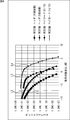
- FIG. 4 is a diagram showing an example of demodulation / decoding performance.
- a curve L1 indicates the demodulation / decoding performance of the header when the MCS number is 2.
- a curve L2 indicates the demodulation / decoding performance of the header when the MCS number is 3.
- a curve L3 indicates the demodulation / decoding performance of the payload when the MCS number is 2.
- a curve L4 shows the demodulation / decoding performance of the payload when the MCS number is 3.
- the error correction code in the payload is a so-called shortened code in which the information word length is 12 bytes with respect to the LDPC code having a code length of 180 bytes.
- the SNR is about 2.5 dB better in the header demodulation / decoding performance when the bit error rate is 1E-6 than in the payload demodulation / decoding performance.
- the header demodulation / decoding performance when the bit error rate is 1E-6 is approximately 3.5 SNR than the payload demodulation / decoding performance. dB better.
- the condition that the header demodulation / decoding performance is equal to or higher than the payload demodulation / decoding performance is satisfied.
- the wireless communication system of FIG. 1 not only the payload modulation method and coding method, but also the header information modulation method and coding method other than the MCS, a method corresponding to the state of the transmission path is used. It becomes possible to select.
- the transmission device 2 can reduce the redundancy of the entire header and improve the transmission efficiency by selecting a modulation method and an encoding method with inferior demodulation / decoding performance when the transmission path is in good condition.
- the transmission apparatus 2 can display information indicating the header modulation method and the coding method as a payload modulation method and a coding method.
- the transmission efficiency can be improved as compared with the case where the information is prepared separately from the information indicating.
- the transmission device 2 can efficiently transmit a frame according to the state of the transmission path.
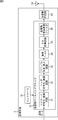
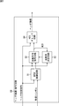
- FIG. 5 is a block diagram illustrating a configuration example of the transmission device 2.
- the transmission device 2 includes a controller 11, a transmission side baseband block 12, a transmission side RF circuit 13, and a transmission antenna 14.
- the controller 11 is composed of a CPU, ROM, RAM, and the like.
- the controller 11 executes a predetermined program and controls the overall operation of the transmission device 2.
- the controller 11 selects the modulation method and coding method of the variable spreading area of the header and the modulation method and coding method of the payload according to the state of the transmission path.
- the modulation method of the variable spreading area of the header and the spreading factor of spreading coding are selected.
- a payload modulation scheme and an error correction coding rate are selected.
- the controller 11 outputs the header storage information including the MCS representing the selected combination to the header encoding / modulation circuit 22 of the transmission-side baseband block 12.
- the header storage information is information including MCS, scrambler ID, frame length, and other frame information. Further, the controller 11 outputs information indicating the payload modulation scheme and the error correction coding rate to the payload coding / modulation circuit 21 of the transmitting baseband block 12.
- the transmission-side baseband block 12 includes a payload encoding / modulation circuit 21, a header encoding / modulation circuit 22, a preamble generation / insertion circuit 23, a transmission filter 24, a D / A (Digital / Analog) conversion circuit 25, and a transmission side
- the low pass filter 26 is configured. Transmission data that is data to be transmitted is input to the payload encoding / modulation circuit 21 of the transmission-side baseband block 12.
- the payload encoding / modulation circuit 21 generates a parity used for error correction based on transmission data, and performs error correction encoding by adding the generated parity to the transmission data. Error correction coding by the payload coding / modulation circuit 21 is performed according to the coding rate selected by the controller 11.
- the payload encoding / modulation circuit 21 modulates the encoded sequence obtained by performing error correction encoding. Modulation by the payload encoding / modulation circuit 21 is performed according to a method selected by the controller 11 such as phase shift keying or quadrature amplitude modulation.
- the payload encoding / modulation circuit 21 outputs the modulated transmission data to the header encoding / modulation circuit 22.
- the header encoding / modulation circuit 22 generates a header including the header storage information supplied from the controller 11 and performs spreading encoding of the generated header.
- the header coding by the header coding / modulation circuit 22 is performed according to the spreading factor selected by the controller 11.
- the header encoding / modulation circuit 22 modulates the encoded sequence of the header obtained by performing spreading encoding.
- the header modulation by the header encoding / modulation circuit 22 is performed according to a method selected by the controller 11 such as quadrature amplitude modulation.
- the header encoding / modulation circuit 22 adds the modulated header to the front of the payload storing the transmission data supplied from the payload encoding / modulation circuit 21 and outputs the result.
- the preamble generation / insertion circuit 23 generates a preamble using a Golay code or the like, and adds it to the front of the header supplied from the header encoding / modulation circuit 22.
- the preamble generation / insertion circuit 23 outputs to the transmission filter 24 a transmission symbol representing frame data composed of a preamble, a header, and a payload.
- the transmission filter 24 performs filtering for band limitation on the transmission symbols supplied from the preamble generation / insertion circuit 23, and outputs the transmission symbols obtained by the filtering.
- the D / A conversion circuit 25 performs D / A conversion on the transmission symbol supplied from the transmission filter 24 and outputs an analog baseband signal.
- the transmission-side low-pass filter 26 filters the analog baseband signal supplied from the D / A conversion circuit 25 to remove out-of-band noise and unnecessary signal components.
- the transmission-side low pass filter 26 outputs an analog baseband signal that has been subjected to filtering.
- the transmission-side RF circuit 13 superimposes the analog baseband signal supplied from the transmission-side low-pass filter 26 on a carrier having a predetermined frequency and transmits it from the transmission antenna 14.
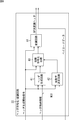
- FIG. 6 is a block diagram showing a configuration example of the header encoding / modulation circuit 22 of FIG.
- the header encoding / modulating circuit 22 includes a header generating circuit 41, a spreading factor determining circuit 42, a spreading encoding circuit 43, and a modulating circuit 44.
- the header generation by the header encoding / modulation circuit 22 is started, for example, at a timing when the header generation start signal output from the controller 11 changes from 0 to 1.
- the header generation start signal is input to each part of the header encoding / modulating circuit 22.
- the header storage information output from the controller 11 is input to the header generation circuit 41, for example, at the same timing as the start of header generation.
- the MCS is also input to the spreading factor determination circuit 42.
- the header generation circuit 41 rearranges the header storage information supplied from the controller 11 in the order shown in FIG. 2, and generates an HCS based on the rearranged information.
- the header generation circuit 41 outputs the header storage information and the HCS to the spread encoding circuit 43.
- the spreading factor determination circuit 42 determines the spreading factor of the variable diffusion region according to the MCS supplied from the controller 11.
- the spreading factor of the variable diffusion region is determined according to, for example, the rules shown in FIG.
- the spreading factor determination circuit 42 outputs information representing the determined spreading factor to the spreading coding circuit 43.
- the spread coding circuit 43 performs spread coding of the header storage information supplied from the header generation circuit 41 and the HCS.
- the spreading coding of the variable spreading area is performed according to the spreading factor determined by the spreading factor determining circuit 42.
- the spreading coding circuit 43 performs spreading coding with a spreading factor of 24 times with respect to the MCS in the fixed spreading area. Also, the spread coding circuit 43 performs spread coding on the information of the variable spread region using the spread rate determined by the spread rate determining circuit 42 out of 2 to 24 times. The spread coding circuit 43 outputs the header storage information and the HCS spread code sequence to the modulation circuit 44.
- the modulation circuit 44 modulates the spread code sequence output from the spread coding circuit 43.
- the modulation of the spread code sequence is performed by the BPSK method according to the rules shown in FIG. 3, for example.
- the modulation circuit 44 adds the transmission symbol obtained by the modulation before the transmission symbol of the payload and outputs it.
- FIG. 7 is a block diagram illustrating a configuration example of the receiving device 3.
- the receiving device 3 includes a receiving antenna 51, a receiving-side RF circuit 52, and a receiving-side baseband block 53.
- the reception-side baseband block 53 includes a variable gain amplification circuit 61, a reception-side low-pass filter 62, an A / D conversion circuit 63, a reception filter 64, a frame detection circuit 65, a symbol synchronization circuit 66, a frame synchronization circuit 67, a header demodulation.
- a decoding circuit 68 and a payload demodulation / decoding circuit 69 are included.
- the transmission signal transmitted from the transmission device 2 is received by the reception antenna 51 and input to the reception side RF circuit 52 as an RF signal.
- the reception-side RF circuit 52 converts the RF signal supplied from the reception antenna 51 into an analog baseband signal and outputs it.
- the variable gain amplification circuit 61 of the reception-side baseband block 53 amplifies or attenuates the power of the analog baseband signal supplied from the reception-side RF circuit 52 according to the dynamic range that can be processed by the A / D conversion circuit 63. Let The variable gain amplifier circuit 61 outputs an analog baseband signal with adjusted power.
- the reception-side low-pass filter 62 limits the band of the analog baseband signal supplied from the variable gain amplification circuit 61. Band limiting by the reception-side low-pass filter 62 is performed in order to prevent generation of a folding signal during A / D conversion.
- the reception-side low-pass filter 62 outputs an analog baseband signal after band limitation.
- the A / D conversion circuit 63 samples the analog baseband signal supplied from the reception-side low-pass filter 62 at, for example, a sample period Tp that is asynchronous with the symbol period Ts.
- the A / D conversion circuit 63 outputs a received signal obtained by sampling.
- the reception filter 64 performs filtering so that the reception signal supplied from the A / D conversion circuit 63 becomes a target equalization channel.
- the reception filter 64 outputs the equalized reception signal.
- the frame detection circuit 65 detects a frame from the reception signal supplied from the reception filter 64 based on, for example, a preamble of a known pattern.
- the frame detection circuit 65 outputs a signal indicating that the frame has been received together with the reception signal supplied from the reception filter 64.
- the symbol synchronization circuit 66 is composed of, for example, an FIR (Finite Impulse Response) filter.
- the symbol synchronization circuit 66 realizes symbol synchronization based on the reception signal supplied from the reception filter 64 and outputs a reception symbol sequence.
- the frame synchronization circuit 67 detects the head position of each of the header and the payload, for example, by detecting a pattern of a known synchronization signal sequence constituting the preamble.
- the frame synchronization circuit 67 outputs the received symbol of the header to the header demodulation / decoding circuit 68 and outputs the received symbol of the payload to the payload demodulation / decoding circuit 69.
- the header demodulation / decoding circuit 68 demodulates and decodes the received symbol of the header supplied from the frame synchronization circuit 67, and acquires header storage information. That is, the header demodulation / decoding circuit 68 demodulates a received symbol modulated by a predetermined method such as quadrature amplitude modulation, and obtains MCS by performing a decoding process using the predetermined method. As described above, encoding and modulation are performed for the MCS by a predetermined method.
- a predetermined method such as quadrature amplitude modulation
- the header demodulation / decoding circuit 68 performs demodulation and decoding of the header storage information and the HCS following the MCS by a method represented by MCS.
- the header demodulation / decoding circuit 68 performs error detection of the header storage information obtained by performing demodulation and decoding based on the HCS, and information indicating the error detection result together with the header storage information and the payload demodulation / decoding circuit 69. Output to.
- the payload demodulation / decoding circuit 69 demodulates the received symbols of the payload supplied from the frame synchronization circuit 67 by a method represented by the MCS supplied from the header demodulation / decoding circuit 68.
- the payload demodulation / decoding circuit 69 performs decoding of the error correction code obtained by demodulation according to the coding rate represented by MCS. Demodulation and decoding by the payload demodulation / decoding circuit 69 is performed when it is determined by the header demodulation / decoding circuit 68 that there is no error in the header storage information.
- the payload demodulation / decoding circuit 69 outputs payload data obtained by performing demodulation and decoding as received data.
- AV data which is received data output from the payload demodulation / decoding circuit 69 is output to the display device 4.
- FIG. 8 is a block diagram showing a configuration example of the header demodulation / decoding circuit 68 of FIG.
- the header demodulation / decoding circuit 68 includes a BPSK demodulation circuit 81, a spreading code decoding circuit 82, a spreading factor determination circuit 83, and an HCS check circuit 84. Decoding of the header by the header demodulation / decoding circuit 68 is started, for example, at a timing when the header head signal output from the frame synchronization circuit 67 changes from 0 to 1. The header head signal is input to each part of the header demodulation / decoding circuit 68. The received symbol of the header is input to the BPSK demodulating circuit 81 at the same timing when decoding of the header is started, for example.
- the BPSK demodulation circuit 81 demodulates the received symbol in the header.
- the header storage information and the HCS spread coded sequence are modulated by the BPSK method according to the rules shown in FIG. 3, for example.
- the BPSK demodulation circuit 81 outputs a spreading code sequence obtained by performing BPSK demodulation to the spreading code decoding circuit 82.
- the spreading code decoding circuit 82 decodes the spreading code sequence supplied from the BPSK demodulation circuit 81. First, the spreading code decoding circuit 82 performs decoding of the fixed spreading area with a spreading factor of 24.
- the encoding method for the MCS in the fixed spreading region is a predetermined method, and in the example of FIG. 3, the spreading rate is 24 times.
- the spreading code decoding circuit 82 outputs the MCS obtained by decoding the fixed spreading area to the spreading factor determining circuit 83. In spreading factor determining circuit 83, the spreading factor of the variable spreading region is determined based on MCS and fed back to spreading code decoding circuit 82.
- the spreading code decoding circuit 82 decodes the variable spreading area in accordance with the spreading factor determined by the spreading factor determining circuit 83, and acquires header storage information and HCS following the MCS.
- the spread code decoding circuit 82 outputs the header storage information and the HCS to the HCS check circuit 84.
- the spreading factor determining circuit 83 determines the spreading factor of the variable spreading area based on the MCS decoded by the spreading code decoding circuit 82.
- the determination of the diffusion rate of the variable diffusion region is performed, for example, according to the rules shown in FIG.
- the spreading factor determining circuit 83 outputs information representing the determined spreading factor to the spreading code decoding circuit 82.
- the HCS check circuit 84 detects an error in the header storage information supplied from the spread code decoding circuit 82 using the HCS.
- the HCS check circuit 84 outputs information indicating the error detection result together with the header storage information.
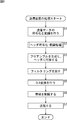
- the processing in FIG. 9 is started when, for example, data output from the playback device 1 is input to the transmission device 2.
- the modulation scheme of the header variable spreading area and the spreading rate of the spreading coding, and the modulation scheme of the payload and the coding rate of the error correction coding are selected in advance by the controller 11.
- step S1 the payload encoding / modulation circuit 21 performs error correction encoding of transmission data according to the encoding rate selected by the controller 11.
- the payload encoding / modulation circuit 21 modulates the encoded sequence obtained by performing error correction encoding according to the method selected by the controller 11.
- step S2 the header encoding / modulation circuit 22 performs header encoding / modulation processing.
- the header generated by the header encoding / modulation process is added to the payload storing the transmission data and output.
- the header encoding / modulation processing will be described later with reference to the flowchart of FIG.
- step S3 the preamble generation / insertion circuit 23 generates a preamble and adds it to the front of the header supplied from the header encoding / modulation circuit 22.
- a transmission symbol representing frame data composed of a preamble, a header, and a payload is supplied to the transmission filter 24.
- step S4 the transmission filter 24 filters the transmission symbols supplied from the preamble generation / insertion circuit 23.
- step S5 the D / A conversion circuit 25 performs D / A conversion on the transmission symbol filtered by the transmission filter 24, and outputs an analog baseband signal.
- step S6 the transmission-side low-pass filter 26 filters the analog baseband signal supplied from the D / A conversion circuit 25 to limit the band.
- step S7 the transmission-side RF circuit 13 transmits the analog baseband signal supplied from the transmission-side low-pass filter 26 from the transmission antenna 14. The above processing is repeated while transmission data is being input.
- step S11 the controller 11 outputs a header generation start signal and header storage information to the header encoding / modulation circuit 22.
- the header storage information output from the controller 11 includes an MCS that represents a combination of a modulation scheme of the variable spreading area of the header and a spreading rate of the spread coding, and a modulation scheme of the payload and a coding rate of the error correction coding.
- step S12 the header generation circuit 41 rearranges the header storage information supplied from the controller 11.
- step S13 the header generation circuit 41 generates HCS based on the header storage information rearranged in the order shown in FIG.
- step S14 the spreading factor determination circuit 42 determines the spreading factor of the variable spreading area based on the MCS included in the header storage information.
- step S15 the spread coding circuit 43 performs spread coding of the header storage information and the HCS generated by the header generation circuit 41.
- the spreading coding circuit 43 performs spreading coding of the fixed spreading region with a predetermined spreading factor, and performs spreading coding of the variable spreading region according to the spreading factor determined by the spreading factor determining circuit 42.
- step S16 the modulation circuit 44 modulates the spreading code sequence in the fixed spreading region using a predetermined method, and modulates the spreading code sequence in the variable spreading region according to the method selected by the controller 11. Thereafter, the process returns to step S2 in FIG. 9, and the subsequent processing is performed.
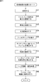
- step S31 the reception-side RF circuit 52 receives the RF signal supplied from the reception antenna 51 and converts it into an analog baseband signal.
- step S32 the variable gain amplification circuit 61 of the reception-side baseband block 53 adjusts the power of the analog baseband signal supplied from the reception-side RF circuit 52.
- step S33 the reception-side low-pass filter 62 limits the band of the analog baseband signal supplied from the variable gain amplification circuit 61.
- step S34 the A / D conversion circuit 63 performs A / D conversion of the analog baseband signal supplied from the reception-side low-pass filter 62.
- step S35 the reception filter 64 filters the reception signal supplied from the A / D conversion circuit 63, and outputs the equalized reception signal.
- step S36 the frame detection circuit 65 detects a frame based on the preamble from the equalized received signal.
- step S37 the symbol synchronization circuit 66 performs symbol synchronization and outputs a received symbol sequence.
- step S38 the frame synchronization circuit 67 detects the start positions of the header and the payload by detecting the pattern of the known synchronization signal sequence that constitutes the preamble.
- the received symbols of the header are supplied to the header demodulation / decoding circuit 68, and the received symbols of the payload are supplied to the payload demodulation / decoding circuit 69.
- step S39 the header demodulation / decoding circuit 68 performs header demodulation / decoding processing.
- the header storage information acquired by the header demodulation / decoding process is output to the payload demodulation / decoding circuit 69 together with information indicating the error detection result of the header storage information.
- the header demodulation / decoding process will be described later with reference to the flowchart of FIG.
- step S 40 the payload demodulation / decoding circuit 69 demodulates the received symbol of the payload supplied from the frame synchronization circuit 67. Demodulation of the received symbol is performed by a method represented by MCS included in the header storage information acquired by the header demodulation / decoding process.
- the payload demodulation / decoding circuit 69 performs decoding of the error correction code obtained by demodulation according to the coding rate represented by MCS. Received data obtained by performing demodulation and decoding is output to the display device 4. The above processing is repeated while the signal transmitted from the transmission device 2 is being received.
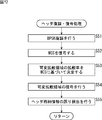
- step S51 the BPSK demodulation circuit 81 performs BPSK demodulation on the received symbol of the header.
- the BPSK demodulation circuit 81 outputs the spreading code sequence obtained by the BPSK demodulation to the spreading code decoding circuit 82.
- step S52 the spreading code decoding circuit 82 performs decoding of the fixed spreading area with a predetermined spreading factor, and acquires MCS.
- step S53 the spreading factor determination circuit 83 determines the spreading factor of the variable diffusion region based on the MCS.
- step S54 the spreading code decoding circuit 82 performs decoding of the variable spreading area according to the spreading factor determined by the spreading factor determining circuit 83, and acquires information and HCS following the MCS included in the header storage information.
- step S55 the HCS check circuit 84 performs error detection of the header storage information supplied from the spread code decoding circuit 82 using the HCS.
- the HCS check circuit 84 outputs information indicating the error detection result together with the header storage information. Thereafter, the process returns to step S39 in FIG. 11, and the subsequent processing is performed.
- the modulation circuit 44 in FIG. 6 performs modulation of the spreading code sequence of the fixed spreading area output from the spreading coding circuit 43 by a predetermined method, and modulates the spreading code sequence of the variable spreading area to determine the spreading factor.
- the method determined by the circuit 42 is performed.
- the BPSK demodulation circuit 81 in FIG. 8 demodulates the received symbols in the fixed spreading area by a predetermined method.
- the spread code decoding circuit 82 performs decoding of the spread coded sequence in the fixed spread region by a predetermined method, and acquires MCS.
- the BPSK demodulation circuit 81 determines a demodulation method for the variable spreading area based on the acquired MCS, and demodulates the received symbols in the variable spreading area.
- the header demodulation / decoding circuit 68 may be provided with a configuration in which the variable spreading region demodulation method is not determined by the BPSK demodulation circuit 81 but the variable spreading region demodulation method is determined based on the MCS.
- the header coding / modulation circuit 22 includes the information representing the other scheme in the header storage information and includes a variable spreading area. Can be stored.
- the demodulation and decoding of the payload by the payload demodulation / decoding circuit 69 is performed based on the information indicating the MCS and the other method stored in the header storage information.
- the payload demodulation / decoding circuit 69 performs one process of demodulation and decoding according to the system represented by MCS, and performs the other process according to the system represented by the information stored in the header storage information.
- the header is divided into two areas, and encoding and modulation can be performed by different methods. However, the encoding and modulation methods for each area are divided into more areas. May be changed.
- the transmission device 2 performs encoding and modulation of MCS, scrambler ID, frame length, and other frame information included in the header storage information by changing the respective methods.
- the MCS arranged at the head of the header is set with a number representing a combination of coding and modulation schemes applied to each piece of information.
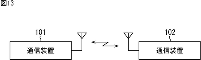
- FIG. 13 is a diagram illustrating another configuration example of the wireless communication system.
- the configuration of the transmission device 2 shown in FIG. 5 and the configuration of the reception device 3 shown in FIG. 7 can be provided in one device.
- the communication device 101 and the communication device 102 can perform transmission data and header storage information encoding and modulation as described above, and transmit data using a frame having the format shown in FIG. Further, the communication device 101 and the communication device 102 can respectively perform demodulation and decoding of the received signal as described above, and acquire transmission data and header storage information.
- FIG. 14 is a block diagram illustrating a configuration example of hardware of a computer that executes the above-described series of processes by a program.
- a CPU Central Processing Unit
- ROM Read Only Memory
- RAM Random Access Memory
- An input / output interface 205 is further connected to the bus 204.
- an input unit 206 such as a keyboard and a mouse and an output unit 207 such as a display and a speaker are connected.
- the input / output interface 205 is connected to a storage unit 208 made up of a hard disk, nonvolatile memory, etc., a communication unit 209 made up of a network interface, etc., and a drive 210 that drives the removable medium 211.
- the CPU 201 loads the program stored in the storage unit 208 to the RAM 203 via the input / output interface 205 and the bus 204 and executes it, thereby executing the above-described series of processing. Is done.
- the program executed by the CPU 201 is recorded in the removable medium 211 or provided via a wired or wireless transmission medium such as a local area network, the Internet, or digital broadcasting, and is installed in the storage unit 208.
- the program executed by the computer may be a program that is processed in time series in the order described in this specification, or in parallel or at a necessary timing such as when a call is made. It may be a program for processing.
- Embodiments of the present technology are not limited to the above-described embodiments, and various modifications can be made without departing from the gist of the present technology.
- the present technology can take a cloud computing configuration in which one function is shared by a plurality of devices via a network and is jointly processed.
- each step described in the above flowchart can be executed by one device or can be shared by a plurality of devices.
- the plurality of processes included in the one step can be executed by being shared by a plurality of apparatuses in addition to being executed by one apparatus.
- the system means a set of a plurality of components (devices, modules (parts), etc.), and it does not matter whether all the components are in the same housing. Accordingly, a plurality of devices housed in separate housings and connected via a network and a single device housing a plurality of modules in one housing are all systems. .
- the communication is not only wireless communication and wired communication, but also communication in which wireless communication and wired communication are mixed, that is, wireless communication is performed in a certain section and wired communication is performed in another section. May be. Further, communication from one device to another device may be performed by wired communication, and communication from another device to one device may be performed by wireless communication.
- the present technology may have the following configurations.
- a payload processing unit for encoding and modulating transmission data stored in the payload Coding and modulation of modulation and coding information representing at least one of coding and modulation for the stored information stored in the header and at least one of coding and modulation for the transmission data
- a coding unit comprising: a transmission unit configured to transmit the frame configured by adding the header including the first area storing the modulation coding information and the second area storing the storage information to the payload. apparatus.
- the header processing unit performs encoding of the modulation encoding information by performing encoding of the modulation encoding information by a method having the highest decoding performance among a plurality of methods used for encoding the stored information.
- the encoding device according to any one of (1) to (3), wherein the encoding is performed by a method having the highest demodulation performance among a plurality of methods used for modulation of the stored information.
- the header processing unit performs encoding of the storage information by a method having a decoding performance equal to or higher than a method used for encoding the transmission data, and modulates the encoded storage information.
- the encoding device according to any one of (1) to (4), wherein the encoding device is performed by a method having a demodulation performance equal to or higher than a method used for modulation.
- Encoding and modulation of the stored information is performed in a manner represented by the modulation encoding information
- An encoding method comprising: transmitting the frame configured by adding the header including the first area for storing the modulation encoding information and the second area for storing the storage information to the payload.
- Coding and modulation of the stored information is performed in a manner represented by the modulation encoding information
- a process including a step of transmitting the frame configured by adding the header composed of a first area for storing the modulation coding information and a second area for storing the storage information to the payload. The program to be executed.
- First modulation encoding information representing at least one of encoding and modulation for storage information stored in the header and at least one of encoding and modulation for transmission data is stored.
- a receiving unit that receives a frame configured by adding the header including a region and a second region that stores the storage information to a payload that stores the transmission data; and
- the modulation and coding information is demodulated and the modulation and coding information after demodulation is decoded by a predetermined method, and the storage information is demodulated and the storage information after demodulation is decoded and acquired.
- a header processing unit that performs the method represented by the modulation and coding information
- a decoding device comprising: a payload processing unit that performs demodulation and decoding of the transmission data in a manner represented by the modulation and coding information acquired by decoding or the modulation and coding information and the storage information.
- the decoding device further including a determination unit that determines a demodulation and decoding scheme of the stored information based on the modulation and coding information obtained by decoding.
- the second area further stores parity used for error detection of the modulation coding information and the stored information,
- the decoding apparatus according to (8) or (9), wherein the header processing unit performs demodulation and decoding of the parity by a method represented by the modulation and coding information acquired by decoding.
- the decoding apparatus further including an error detection unit configured to detect an error between the modulation coding information and the storage information based on the parity obtained by decoding.
- First modulation encoding information representing at least one of encoding and modulation for storage information stored in the header and at least one of encoding and modulation for transmission data is stored.
- Receiving a frame configured by adding the header composed of an area and a second area for storing the storage information to a payload for storing the transmission data; Performing demodulation of the modulation encoding information and decoding of the modulation encoding information after demodulation in a predetermined manner, Demodulating the stored information and decoding the stored information after demodulation are performed in a manner represented by the modulation and coding information obtained by decoding,
- a decoding method including a step of performing demodulation and decoding of the transmission data in a manner represented by the modulation and coding information obtained by decoding or the modulation and coding information and the storage information.
- First modulation encoding information representing at least one of encoding and modulation for storage information stored in the header and at least one of encoding and modulation for transmission data is stored.
- Receiving a frame configured by adding the header composed of an area and a second area for storing the storage information to a payload for storing the transmission data; Performing demodulation of the modulation encoding information and decoding of the modulation encoding information after demodulation in a predetermined manner, Demodulating the stored information and decoding the stored information after demodulation are performed in a manner represented by the modulation and coding information obtained by decoding,
- a program that causes a computer to execute processing including a step of performing demodulation and decoding of the transmission data in a manner represented by the modulation and coding information obtained by decoding or the modulation and coding information and the storage information.
- a payload processing unit for encoding and modulating transmission data stored in the payload Coding and modulation of modulation and coding information representing at least one of coding and modulation for the stored information stored in the header and at least one of coding and modulation for the transmission data
- a coding unit comprising: a transmission unit configured to transmit the frame configured by adding the header including the first area storing the modulation coding information and the second area storing the storage information to the payload.
- the modulation and coding information is demodulated and the modulation and coding information after demodulation is decoded by a predetermined method, and the storage information is demodulated and the storage information after demodulation is decoded and acquired.
- a header processing unit that performs the method represented by the modulation and coding information;
- a decoding device comprising: a payload processing unit that performs demodulation and decoding of the transmission data in a manner represented by the modulation and coding information obtained by decoding or the modulation and coding information and the storage information. Communications system.
Landscapes
- Engineering & Computer Science (AREA)
- Signal Processing (AREA)
- Computer Networks & Wireless Communication (AREA)
- Quality & Reliability (AREA)
- Detection And Prevention Of Errors In Transmission (AREA)
- Mobile Radio Communication Systems (AREA)
- Compression Or Coding Systems Of Tv Signals (AREA)
Priority Applications (3)
| Application Number | Priority Date | Filing Date | Title |
|---|---|---|---|
| US15/531,121 US10477432B2 (en) | 2014-12-16 | 2015-12-02 | Encoding device, encoding method, decoding device, decoding method, program, and wireless communication system |
| CN201580067230.2A CN107005356B (zh) | 2014-12-16 | 2015-12-02 | 编码装置、编码方法、解码装置、解码方法、存储介质及无线通信系统 |
| EP15869798.7A EP3236607A4 (en) | 2014-12-16 | 2015-12-02 | Encoding device, encoding method, decoding device, decoding method, program, and wireless communication system |
Applications Claiming Priority (2)
| Application Number | Priority Date | Filing Date | Title |
|---|---|---|---|
| JP2014254155A JP6618252B2 (ja) | 2014-12-16 | 2014-12-16 | 符号化装置、符号化方法、復号装置、復号方法、プログラム、および通信システム |
| JP2014-254155 | 2014-12-16 |
Publications (1)
| Publication Number | Publication Date |
|---|---|
| WO2016098592A1 true WO2016098592A1 (ja) | 2016-06-23 |
Family
ID=56126486
Family Applications (1)
| Application Number | Title | Priority Date | Filing Date |
|---|---|---|---|
| PCT/JP2015/083896 Ceased WO2016098592A1 (ja) | 2014-12-16 | 2015-12-02 | 符号化装置、符号化方法、復号装置、復号方法、プログラム、および無線通信システム |
Country Status (5)
| Country | Link |
|---|---|
| US (1) | US10477432B2 (enExample) |
| EP (1) | EP3236607A4 (enExample) |
| JP (1) | JP6618252B2 (enExample) |
| CN (1) | CN107005356B (enExample) |
| WO (1) | WO2016098592A1 (enExample) |
Families Citing this family (5)
| Publication number | Priority date | Publication date | Assignee | Title |
|---|---|---|---|---|
| CN106575977B (zh) * | 2014-08-20 | 2019-03-15 | 索尼半导体解决方案公司 | 接收设备、帧同步方法、传输设备、传输方法和程序 |
| WO2019076340A1 (en) * | 2017-10-18 | 2019-04-25 | Zte Corporation | FRAME HEADERS FOR MULTI-LEVEL MODULATED SIGNALS IN PASSIVE OPTICAL NETWORKS |
| JP6907948B2 (ja) * | 2018-01-04 | 2021-07-21 | 富士通株式会社 | ファイル生成プログラム、ファイル生成方法及びファイル生成装置 |
| CN111919453A (zh) * | 2018-04-05 | 2020-11-10 | 索尼半导体解决方案公司 | 发送装置、接收装置以及通信系统 |
| JP2022507567A (ja) | 2018-11-14 | 2022-01-18 | スカイウェイブ・ネットワークス・エルエルシー | 上空波システムにおける変速 |
Citations (3)
| Publication number | Priority date | Publication date | Assignee | Title |
|---|---|---|---|---|
| JP2007243234A (ja) * | 2006-03-03 | 2007-09-20 | Sony Corp | 無線通信装置及び無線通信方法 |
| JP2012521131A (ja) * | 2009-03-19 | 2012-09-10 | コーニンクレッカ フィリップス エレクトロニクス エヌ ヴィ | Plcpヘッダを符号化する技術 |
| JP2012527824A (ja) * | 2009-06-02 | 2012-11-08 | インテル コーポレイション | Macヘッダプロテクションを増大させる装置及び方法 |
Family Cites Families (5)
| Publication number | Priority date | Publication date | Assignee | Title |
|---|---|---|---|---|
| US20030135797A1 (en) * | 2002-01-15 | 2003-07-17 | Sunghyun Choi | Method and apparatus for enhancing the transmission of error in the IEEE 802.11e systems |
| JP5283067B2 (ja) | 2008-09-18 | 2013-09-04 | 独立行政法人情報通信研究機構 | ヘッダ最適化フィールドを有するプリアンブルを用いた無線通信方法 |
| CN102246518B (zh) * | 2008-12-15 | 2013-11-13 | Lg电子株式会社 | 用于发送和接收信号的装置以及用于发送和接收信号的方法 |
| US9112753B2 (en) * | 2010-05-11 | 2015-08-18 | Texas Instruments Incorporated | Interleaver design and header structure for ITU G.hnem |
| KR101829923B1 (ko) * | 2011-10-13 | 2018-02-22 | 삼성전자주식회사 | 데이터 통신 시스템에서 부호화 장치 및 방법 |
-
2014
- 2014-12-16 JP JP2014254155A patent/JP6618252B2/ja active Active
-
2015
- 2015-12-02 US US15/531,121 patent/US10477432B2/en active Active
- 2015-12-02 WO PCT/JP2015/083896 patent/WO2016098592A1/ja not_active Ceased
- 2015-12-02 EP EP15869798.7A patent/EP3236607A4/en not_active Withdrawn
- 2015-12-02 CN CN201580067230.2A patent/CN107005356B/zh not_active Expired - Fee Related
Patent Citations (3)
| Publication number | Priority date | Publication date | Assignee | Title |
|---|---|---|---|---|
| JP2007243234A (ja) * | 2006-03-03 | 2007-09-20 | Sony Corp | 無線通信装置及び無線通信方法 |
| JP2012521131A (ja) * | 2009-03-19 | 2012-09-10 | コーニンクレッカ フィリップス エレクトロニクス エヌ ヴィ | Plcpヘッダを符号化する技術 |
| JP2012527824A (ja) * | 2009-06-02 | 2012-11-08 | インテル コーポレイション | Macヘッダプロテクションを増大させる装置及び方法 |
Non-Patent Citations (1)
| Title |
|---|
| See also references of EP3236607A4 * |
Also Published As
| Publication number | Publication date |
|---|---|
| EP3236607A1 (en) | 2017-10-25 |
| JP6618252B2 (ja) | 2019-12-11 |
| CN107005356A (zh) | 2017-08-01 |
| US10477432B2 (en) | 2019-11-12 |
| EP3236607A4 (en) | 2018-10-10 |
| CN107005356B (zh) | 2020-09-29 |
| JP2016116115A (ja) | 2016-06-23 |
| US20170367006A1 (en) | 2017-12-21 |
Similar Documents
| Publication | Publication Date | Title |
|---|---|---|
| US10581659B2 (en) | System and method for communications with reduced peak to average power ratio | |
| JP5423798B2 (ja) | 符号化および復号方法およびその装置 | |
| US9131528B2 (en) | Physical layer frame format for WLAN | |
| JP6618252B2 (ja) | 符号化装置、符号化方法、復号装置、復号方法、プログラム、および通信システム | |
| KR100719840B1 (ko) | 시공간 주파수 블록 부호화 장치 및 방법 | |
| JP2003283582A (ja) | マルチキャストデータの送受信装置及び方法 | |
| US9780910B2 (en) | Systems and methods for multiple stream encoded digital video | |
| JP2007243951A (ja) | 多重入力多重出力方式を使用する通信システムの信号送受信装置及び方法 | |
| JP2010509861A5 (enExample) | ||
| US11258650B2 (en) | Communication method, communications apparatus, and storage medium | |
| KR102766353B1 (ko) | 신호를 수신하기 위한 방법 및 장치 | |
| JP2008245128A (ja) | Ofdmを用いた無線送信装置と方法及び無線受信装置と方法 | |
| Frenzel | What’s the difference between bit rate and baud rate | |
| US9014320B1 (en) | Interference whitening filters for MIMO maximum likelihood receivers | |
| EP2408161A1 (en) | Data transmission device and method thereof, and data reception device and method thereof | |
| CN107277566B (zh) | 基于叠加编码的信令编码调制方法及解调译码方法 | |
| Yoo et al. | Bridging neural networks and wireless systems with MIMO-OFDM semantic communications | |
| JP6251132B2 (ja) | 符号化装置、符号化方法、復号装置、復号方法、およびプログラム | |
| US20140029697A1 (en) | GMSK-Based Modulation in a Wireless Local Area Network | |
| IL234189A (en) | A method for generating an enhanced frame vcm or acm signal | |
| WO2007043097A9 (ja) | 送信装置、受信装置、送信方法、受信方法、情報記録媒体、および、プログラム | |
| HK1164025B (en) | A method and apparatus for encoding and decoding |
Legal Events
| Date | Code | Title | Description |
|---|---|---|---|
| 121 | Ep: the epo has been informed by wipo that ep was designated in this application |
Ref document number: 15869798 Country of ref document: EP Kind code of ref document: A1 |
|
| WWE | Wipo information: entry into national phase |
Ref document number: 15531121 Country of ref document: US |
|
| REEP | Request for entry into the european phase |
Ref document number: 2015869798 Country of ref document: EP |
|
| NENP | Non-entry into the national phase |
Ref country code: DE |