WO2016092949A1 - アルミニウム棒材のピーリング方法 - Google Patents
アルミニウム棒材のピーリング方法 Download PDFInfo
- Publication number
- WO2016092949A1 WO2016092949A1 PCT/JP2015/079043 JP2015079043W WO2016092949A1 WO 2016092949 A1 WO2016092949 A1 WO 2016092949A1 JP 2015079043 W JP2015079043 W JP 2015079043W WO 2016092949 A1 WO2016092949 A1 WO 2016092949A1
- Authority
- WO
- WIPO (PCT)
- Prior art keywords
- aluminum bar
- aluminum
- cutting
- bar
- cut
- Prior art date
- Legal status (The legal status is an assumption and is not a legal conclusion. Google has not performed a legal analysis and makes no representation as to the accuracy of the status listed.)
- Ceased
Links
Images


Classifications
-
- B—PERFORMING OPERATIONS; TRANSPORTING
- B23—MACHINE TOOLS; METAL-WORKING NOT OTHERWISE PROVIDED FOR
- B23B—TURNING; BORING
- B23B1/00—Methods for turning or working essentially requiring the use of turning-machines; Use of auxiliary equipment in connection with such methods
-
- B—PERFORMING OPERATIONS; TRANSPORTING
- B23—MACHINE TOOLS; METAL-WORKING NOT OTHERWISE PROVIDED FOR
- B23B—TURNING; BORING
- B23B13/00—Arrangements for automatically conveying or chucking or guiding stock
-
- B—PERFORMING OPERATIONS; TRANSPORTING
- B23—MACHINE TOOLS; METAL-WORKING NOT OTHERWISE PROVIDED FOR
- B23B—TURNING; BORING
- B23B5/00—Turning-machines or devices specially adapted for particular work; Accessories specially adapted therefor
- B23B5/08—Turning-machines or devices specially adapted for particular work; Accessories specially adapted therefor for turning axles, bars, rods, tubes, rolls, i.e. shaft-turning lathes, roll lathes; Centreless turning
- B23B5/12—Turning-machines or devices specially adapted for particular work; Accessories specially adapted therefor for turning axles, bars, rods, tubes, rolls, i.e. shaft-turning lathes, roll lathes; Centreless turning for peeling bars or tubes by making use of cutting bits arranged around the workpiece
Definitions
- the present invention relates to a peeling method of an aluminum bar and its related technology in which the outer peripheral surface of the aluminum bar is removed by cutting with a cutting blade.
- aluminum is used to include an aluminum alloy (Al alloy).
- a round bar-shaped aluminum bar used as a forging material or the like is constituted by, for example, a continuous cast bar.
- a continuous casting bar (bar material) obtained by casting is subjected to a cutting process, a heat treatment process (homogenization process), and a pre-correction process (first).
- An integrated production line is known in which a correction process), a peeling process (surface cutting process), a post-correction process (second correction process), and an appearance inspection process are sequentially performed and then packed and unloaded.
- This peeling apparatus includes a cutting blade that is rotationally driven in the circumferential direction along the outer peripheral surface of the aluminum bar, and rotates the cutting blade while conveying the aluminum bar in the length direction, thereby allowing the outer periphery of the aluminum bar to be rotated. The surface is cut and removed.
- an upstream conveying machine such as a conveying roller for gripping and feeding an aluminum bar to the cutting blade is disposed on the upstream side of the cutting blade, and the cut aluminum is disposed on the downstream side.
- a downstream conveying machine such as a carriage for gripping the rod material and carrying it out from the cutting blade is disposed.
- This invention has been made in view of the above problems, and can accurately and reliably cut the surface of an aluminum bar, while preventing bending deformation of the aluminum bar and reducing the load on the cutting blade. It is an object of the present invention to provide an aluminum bar manufacturing method and related technology capable of improving durability.
- the aluminum bar conveyed by the upstream conveying machine is passed through the upstream supporting machine, the cutting machine, and the downstream supporting machine, and unloaded by the downstream conveying machine, while passing through the cutting machine.
- a method for peeling an aluminum bar material by cutting the outer peripheral surface of the aluminum bar material by rotating the cutting blade along the outer peripheral surface of By causing the gripping force to the aluminum bar by the transporter of at least one of the upstream transporter and the downstream transporter to act as a braking force against the rotational force of the aluminum bar generated by the rotation of the cutting blade.
- the ratio of the rotational speed of the aluminum bar to the rotational speed of the cutting blade is adjusted to 0.01% to 0.2% while rotating the cutting blade and the aluminum bar in the same direction.
- a method for peeling aluminum bars is adjusted to 0.01% to 0.2% while rotating the cutting blade and the aluminum bar in the same direction.
- the upstream-side transport machine has a pair of transport rollers in which a transport surface is formed in a V-groove shape and transports the aluminum rod while sandwiching it.
- a point contact biting protrusion is provided on the conveying surface of the conveying roller, and the point contact biting protrusion is bitten into the outer peripheral surface of the aluminum bar to obtain a grip force of the conveying roller on the aluminum bar. 3.
- the aluminum bar has a predetermined length, and a plurality of aluminum bars are sequentially and continuously transported by the upstream transport machine, In a state where the rear end of the aluminum bar being cut by the cutting machine is pulled out from the upstream support machine to the downstream side, the tip of the subsequent aluminum bar supported by the upstream support machine is being cut.
- the rear end side of the aluminum bar being cut is supported by the upstream support machine via the subsequent aluminum bar by frictional contact with the rear end of the preceding aluminum bar.
- the aluminum bar has a predetermined length, and a plurality of aluminum bars are successively transferred from the upstream transfer machine toward the cutting machine.
- the tip of the subsequent aluminum bar gripped by the upstream conveyor is being cut.
- the braking force based on the grip force of the upstream conveyor is transmitted to the aluminum bar being cut through the subsequent aluminum bar.
- the aluminum bar has a predetermined length, and a plurality of aluminum bars are successively transferred from the upstream side transfer machine toward the cutting machine, When the front end of the aluminum bar being cut by the cutting machine has not reached the downstream support machine, the rear end of the preceding aluminum bar that has been cut and supported by the downstream support machine is cut. Any one of the preceding items 1 to 5, wherein the front end side of the aluminum bar being cut is supported by the downstream support machine via the preceding aluminum bar by friction contact with the tip of the aluminum bar inside The peeling method of the aluminum bar material of 1 item
- the aluminum bar has a predetermined length, and a plurality of aluminum bars are sequentially and continuously conveyed from the upstream conveyor toward the cutting machine, When the front end of the aluminum bar that is being cut by the cutting machine has not reached the downstream conveyor, the rear end of the preceding aluminum bar that has been gripped by the downstream conveyor is cut.
- the preceding item 1 wherein the braking force based on the grip force of the downstream conveying machine is transmitted to the aluminum bar being cut through the preceding aluminum bar by making frictional contact with the tip of the inner aluminum bar. 7.
- the method for peeling an aluminum bar according to any one of items 1 to 6.
- the end face of the aluminum bar is any one of the above items 4 to 9, wherein the end surface is formed on a surface having a ratio of surface roughness Ry or Ra of one direction and the other direction orthogonal to the double direction more than twice. Peeling method for aluminum bar.
- the end face of the aluminum bar is any one of the above items 4 to 10, wherein the end face of the aluminum line is formed on a surface having irregularities having an inclination (absolute value) of 100 or more between adjacent peaks and valleys in the contour curve
- the aluminum bar conveyed by the upstream conveying machine passes through the upstream supporting machine, the cutting machine, and the downstream supporting machine and is unloaded by the downstream conveying machine, while passing through the cutting machine.
- An aluminum bar peeling apparatus in which the outer peripheral surface of the aluminum bar is cut by rotating the cutting blade along the outer peripheral surface of the material, A structure in which a gripping force to the aluminum bar by the at least one of the upstream conveyor and the downstream conveyor is applied as a braking force to the rotational force of the aluminum bar generated by the rotation of the cutting blade.
- a peeling apparatus for an aluminum bar wherein the gripping force to the aluminum bar by the upstream side conveyor and the downstream side conveyor is adjustable.
- the outer peripheral surface of the aluminum bar can be reliably cut by the cutting blade. Furthermore, since the grip force (pressing force) from the conveyor to the aluminum bar can be dispersed in the circumferential direction, it is possible to prevent bending of the aluminum bar and to reduce the impact on the cutting blade. Durability can be obtained.
- the gripping force of the conveyor can be used as a braking force by the aluminum bar, and the above effect can be obtained more reliably.
- the supporting force and the braking force can be transmitted to the aluminum bar being cut through the aluminum bars before and after the aluminum bar being cut. Sufficient support force and braking force can be applied to the bar.
- the same effect as in the above method invention can be obtained by adjusting the grip force to the aluminum bar by the upstream and downstream conveyors. .
- FIG. 1 is a perspective view showing an aluminum bar peeling apparatus according to an embodiment of the present invention.
- FIG. 2 is a block diagram illustrating the peeling apparatus according to the embodiment.
- FIG. 3 is a front view showing a roller support machine in the peeling apparatus of the embodiment.
- FIG. 4 is a front view showing the conveying roller in the peeling apparatus according to the embodiment.
- FIG. 5 is a side view showing an aluminum bar cut by the peeling apparatus of the embodiment.
- FIG. 6 is a graph showing the relationship between the grip force and the rotation ratio in the peeling device.
- FIG. 7A is a block diagram for explaining a support state of the minium bar by the peeling device.
- FIG. 7B is a block diagram for explaining the state of supporting the pushing of the minium bar by the peeling device.
- FIG. 7A is a block diagram for explaining a support state of the minium bar by the peeling device.
- FIG. 7B is a block diagram for explaining the state of supporting the pushing of the minium
- FIG. 7C is a block diagram for explaining a push-in support state of the minium bar material by the peeling device.
- FIG. 8A is a block diagram for explaining a cantilever state of a minium bar by a peeling device.
- FIG. 8B is a block diagram for explaining a cantilever state of the minium bar by the peeling device.
- An aluminum bar peeling method is suitably employed in a peeling process in an integrated production line for continuous casting bar production.
- This integrated production line includes a casting process for obtaining a continuous cast bar, a cutting process for cutting the continuous cast bar, a heat treatment process for heat treating the cut continuous cast bar for homogenization, softening, and hardening.
- a pre-correcting process for correcting the bending of the continuous cast bar, a peeling process for cutting and removing the surface of the pre-corrected continuous cast bar, and correcting the bending of the continuous cast bar with which the surface is contacted It includes a post-correction process (second correction process), an appearance inspection process for inspecting the post-corrected continuous cast bar, and a packing process for packing the inspected continuous cast bar.
- the material of the aluminum bar processed in this integrated production line is not particularly limited as long as it is pure aluminum or an aluminum alloy.
- the wrought material having an alloy number of 2000 series, 4000 series, 6000 series, etc.
- Aluminum alloys for casting and alloys for casting such as A390 alloy can be suitably used.
- a round bar having a diameter of 25 mm to 125 mm can be suitably used as the aluminum bar.
- the outer peripheral surface is removed for the purpose of removing the reverse segregation layer on the surface of an aluminum bar constituted by, for example, a continuous cast bar.
- the range of the reverse segregation layer is determined by the composition of the continuous casting rod at the time of casting, the structure of the mold, the casting conditions, and the like.
- the thickness of the reverse segregation layer is in the range of about 0.1 mm to 2 mm from the surface.
- the range from the surface to a depth of about 1 mm is an example of a casting surface that is likely to have a defect due to the aluminum alloy molten metal coming into contact with the mold, lubricating oil, or gas, and should be removed. . Therefore, in the present embodiment, it is preferable to remove the casting surface having a depth of about 1 mm to 2 mm from the surface so that the reverse segregation layer, defects, and the like can be reliably removed.
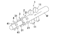
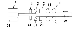
- FIG. 1 is a perspective view showing a peeling device of this embodiment adopted in the peeling process
- FIG. 2 is a block diagram showing the peeling device of the embodiment
- FIG. 3 is a front view showing a roller support machine of the peeling device of the embodiment. It is.
- this peeling device is composed of a roller transport machine 1 as an upstream transport machine and an upstream support machine from the upstream side to the downstream side along the transport line of the aluminum bar W.
- An upstream roller support machine 2, a cutting machine 3, a downstream roller support machine 4 as a downstream support machine, and a carriage 5 as a downstream transport machine are arranged in this order.
- the cutting machine 3 is provided with cutting blades 31 at four locations at regular intervals (90 ° intervals) in the circumferential direction along the outer peripheral surface of the aluminum bar W conveyed along the conveyance line.
- the cutting tool 31 of each location can use suitably the combination tool
- the number of cutting blades (blades) is not limited, and a cutting blade other than a combination tool may be used.
- the aluminum bar W is transported along the transport line while rotating the cutting blade 31, so that the outer peripheral surface of the aluminum bar W is removed by the cutting blade 31 without being left uncut. It has become.
- the aluminum bar W since the cutting blade 31 is cut along the outer peripheral surface of the aluminum bar W during cutting, the aluminum bar W will rotate about its axis as the cutting blade 31 rotates. A rotational force is generated. Accordingly, if the rotation of the aluminum bar W is not restricted, the aluminum bar W rotates in the same direction following the rotation of the cutting blade 31, so-called rotation occurs. As will be described in detail later, in the present embodiment, the rotation of the aluminum bar W is moderately suppressed by the grip force of the roller conveyor 1 and the carriage 5 with respect to the aluminum bar W.
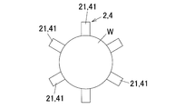
- the upstream roller support machine 2 and the downstream roller support machine 4 include a plurality of upstream support rollers 21 and a plurality of downstream support rollers 41 at equal intervals along the outer circumferential surface of the aluminum bar W in the circumferential direction.
- the support rollers 21 and 41 roll on the outer peripheral surface of the aluminum bar W as the aluminum bar W is conveyed.
- the number of rollers installed in the upstream roller support machine 2 and the downstream roller support machine 4 is not particularly limited.
- each roller support machine has 4 to 12 rollers. Can be suitably used.
- the upstream side support roller 21 and the downstream side support roller 41 also serve as guide rollers and support the aluminum bar W while guiding it.
- the upstream roller support machine 2 and the downstream roller support machine 4 are shown redundantly.
- the support rollers 21 and 41 do not impart conveying force to the aluminum bar W. Furthermore, in the present embodiment, the support rollers 21 and 41 have a braking force for restricting the rotation of the aluminum bar W that rotates with the cutting blade 31 in the direction around the axis, which is not zero. 1 and the carriage 5 are negligibly small.
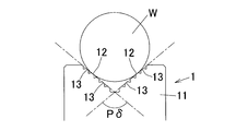
- the roller transport machine 1 includes a transport roller (feed roller) 11 made up of a total of four V-groove rollers, two in the vertical direction and two in the transport line. As shown in FIG. 1 and FIG. 4, each conveyance roller 11 is configured such that the inner surfaces on both sides of the V-groove are configured as a conveyance surface 12. Each conveyance surface 12 of each conveyance roller 11 is pressed against the outer peripheral surface of the aluminum bar W so that the aluminum bar W is gripped. In this gripping state, the conveyance roller 11 is rotationally driven by a roller drive mechanism (not shown), so that the aluminum bar W is conveyed downstream along the conveyance line.
- the gripping force (gripping force) of the aluminum bar W by the roller conveyor 1 is a braking force with respect to the rotational force of the aluminum bar W trying to rotate around the axis along with the rotation of the cutting blade 31. It comes to work.
- the conveyance surface 12 of the conveyance roller 11 has a large number of point contact biting protrusions 13.
- the aluminum bar W is gripped by causing the biting protrusions 12 to bite into the outer peripheral surface of the aluminum bar W in a point contact manner. That is, the gripping force of the transport roller 11 is not determined by the frictional force due to the surface contact of the aluminum bar W, but is determined by the amount of biting of the point contact biting protrusion 13 and the pressing force.
- the point contact biting protrusion 12 can be formed by, for example, rolling knurl processing, cutting knurl processing, other cutting processing, or the like.
- the carriage 5 includes a pair of upper and lower clamping blocks 51, 51, and a conveying surface as an opposing surface (a clamping surface) of both blocks 51 is formed in a V-shaped groove.
- the gripped parts can be gripped by sandwiching the cut portion of the aluminum bar W from above and below by the sandwiching blocks 51 and 51. In this state, the aluminum bar W can be unloaded from the cutting machine 3 to the downstream side.
- the gripping force (gripping force) of the aluminum bar W by the carriage 5 acts as a braking force on the rotational force of the aluminum bar W that is about to rotate around the axis as the cutting blade 31 rotates. It has become.
- the conveying surface of the clamping block 51 is a smooth surface so that the surface of the aluminum bar W is not carelessly damaged. Is formed.
- the aluminum bar W fed from the roller conveyor 1 is drawn by the carriage 5 through the upstream roller support machine 2, the cutting machine 3, and the downstream roller support machine 4. So that it is conveyed.
- the cutting blade 31 rotates in the circumferential direction along the outer peripheral surface of the aluminum bar W, whereby the outer peripheral surface of the aluminum bar W is cut. Removed.
- the aluminum bar W rotates in the same direction around the axis along with the rotation of the cutting blade 31 at the time of cutting, while the roller conveyor 1 and the carriage against the rotational force of the aluminum bar W.
- the grip force of 5 to act as a braking force, the aluminum bar W is adjusted to rotate at a predetermined rotational speed with respect to the rotational speed of the cutting blade 31.
- the rotation speed of the cutting blade 31 is “Pa”
- the rotation speed of the aluminum bar W is “Pb”
- the ratio of the rotation speed Pa of the aluminum bar W to the rotation speed Pb of the cutting blade 31 is “
- the diameter of the aluminum bar W before cutting is 25 mm to 125 mm, it is preferable to set the rotational speed of the aluminum bar W to 0.15 rpm to 3.0 rpm.
- the pressing force acting on the aluminum bar W from the conveying roller 11 concentrates on a part of the circumferential direction of the aluminum bar W and acts strongly. Cannot be dispersed, and the aluminum bar W may be bent and deformed so that it bows.
- the torque between the processing blade 31 and the processed surface (outer peripheral surface) of the aluminum bar W increases, particularly when there is a change in the state of the aluminum bar W, for example, there is bending or cutting.
- the target part is altered or the like, the torque cannot be relaxed, the load on the cutting blade 31 becomes abnormally large, the cutting performance is extremely lowered, or the blade spills. May occur.
- the aluminum bar W has too many revolutions, the cutting blade 31 is in a state of sliding with respect to the aluminum bar W, and the finish of the machined surface is deteriorated. To do.
- the pressing force acting on the aluminum bar W from the transport roller 11 is set to a wide range in the circumferential direction of the aluminum bar W by setting the rotation speed of the aluminum bar W within the above specific range. It is possible to disperse and prevent bending deformation of the aluminum bar W, and the outer peripheral surface of the aluminum bar W can be stably cut by the cutting blade 31, and a cutting surface having a good finish can be efficiently obtained. Obtainable.
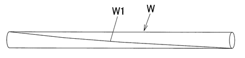
- the aluminum bar W cut by the peeling method of the present embodiment has a roller trace (spiral trace) W1 formed by the support roller 41 of the downstream roller support machine 4 spirally formed on the outer peripheral surface thereof. Is formed.
- the roller mark W ⁇ b> 1 is formed at least at one place by at least one support roller 41 among the plurality of support rollers 41.
- this roller mark W1 is not necessarily formed continuously over the entire length direction of the aluminum bar W, and there may be a case where one or more portions in the length direction are partially lost.
- the pitch of the roller marks W1 corresponds to the above rotation ratio Pc.
- the rotation amount (angle) per meter is set to 15 ° / m to 120 ° / m. Has been.
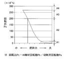
- FIG. 6 is a graph showing the relationship between the grip force (gripping force) and the rotation ratio Pc, where the vertical axis represents the rotation ratio Pc and the horizontal axis represents the grip force (gripping force). As shown in the figure, there is a correlation between the rotation ratio Pc and the grip force. Therefore, by adjusting the grip force and controlling the rotation ratio Pc within the above specific range, it is possible to reliably obtain the above effect.
- the rotation ratio Pc decreases and becomes an area A1 of less than 0.01.
- the amount of rotation of the aluminum bar W is reduced, and the grip force is concentrated on a part in the circumferential direction, so that bending deformation or the like occurs.
- the rotation ratio Pc increases, and the region A3 is over 0.2 and close to 0.27. In this case, the rotation amount of the aluminum bar W increases, and the cutting blade 31 slides with respect to the aluminum bar W, so that a good cutting surface (processed surface) cannot be obtained. Further, when the grip force is set to be large, the rotation ratio Pc becomes very small and the region A4 exceeds 0.27. In this case, the propelling force of the aluminum bar W is lost, the aluminum bar W hardly moves forward, cutting is not possible, and manufacture is impossible.
- the rotation ratio Pc is adjusted to a region A2 of 0.01 or more and 0.2 or less, that is, a suitable region A, and as described above, problems such as bending deformation are reliably prevented.
- a cut surface processed surface
- a good finish it is possible to efficiently obtain a cut surface (processed surface) with a good finish.
- the aluminum bar W processed by the peeling device is sequentially supplied to the roller transporter 1, the upstream roller supporter 2, the cutting machine 3, the downstream roller supporter 4, and the carriage 5.
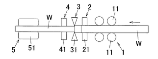
- the aluminum bar W Is cut to a predetermined length, so that when individually cutting the aluminum bar W one by one, for example, immediately after the front end of the aluminum bar W reaches the cutting machine 3 as shown in FIG.
- the aluminum bar W is not supported at the front side (immediately after the start of cutting), and the support state becomes unstable.
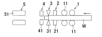
- FIG. 8A immediately before the rear end of the aluminum bar W is pulled out of the cutting machine 3 (immediately before the end of cutting), the rear side of the aluminum bar W is not supported and the support state becomes unstable.
- the front end of the aluminum bar W is gripped by the carriage 5, and then the rear end comes out of the roller transporter 1.
- the aluminum bar W is cut individually one by one, as shown in FIG. 8A, the aluminum bar W is in a state immediately before the cutting of the aluminum bar W being cut as described above.
- the rear end of the material W is pulled out from the upstream roller support machine 2 to the downstream side and is not supported, and only the front side is in a one-side support state (cantilever state) supported by the downstream roller support machine 4 and the carriage 5. ing.
- the aluminum bar W is shaken, and chattering may occur and cutting may not be performed with high accuracy.
- the grip force (braking force) of the roller conveyor 1 since the grip force (braking force) of the roller conveyor 1 is not transmitted to the aluminum bar W, the braking force of the aluminum bar W itself may be insufficient, and the predetermined rotation ratio Pc is adjusted. In this case, the finished surface cannot be obtained with a good finish, and the amount of rotation of the aluminum bar W increases, which may make the cutting process impossible. If the grip force (pressing force) by the carriage 5 is increased to adjust the rotation speed to a predetermined number of rotations, problems such as formation of scratches or indentations on the processed surface after cutting occur.
- the aluminum bar W is continuously formed without any interval.
- the front end surface of the subsequent uncut aluminum rod W is brought into contact with the rear end surface of the aluminum rod W being cut.
- the rear end of the aluminum bar W being cut and the front end of the subsequent aluminum bar W are friction-bonded and integrated (pseudo-fitting)
- the rear end of the aluminum bar W being cut is Further, it is indirectly supported by the upstream roller supporter 2 and the roller transporter 1 through the subsequent aluminum bar W.
- chattering can be reliably prevented and cutting can be performed with high accuracy.
- the grip force (braking force) is transmitted to the aluminum bar W being cut through the subsequent aluminum bar W. That is, since the aluminum bar W during cutting can cause the gripping forces of both the roller conveyor 1 and the carriage 5 to act as a braking force against the rotational force of the aluminum bar W, a sufficient braking force can be obtained. Can do. For this reason, the amount of rotation of the aluminum bar W can be accurately controlled, the specific rotation ratio Pc can be obtained with certainty, and good cutting can be efficiently performed as described above.
- the aluminum bar W is continuously supplied without a gap, so that the front end surface of the aluminum bar W immediately after the cutting process is started has been cut. Are brought into contact with the rear end surface of the preceding aluminum bar W and integrated by friction bonding. For this reason, the front side of the aluminum bar W being cut is indirectly supported by the downstream roller support machine 4 and the carriage 5 via the preceding aluminum bar W. It can be supported and cut with high accuracy.
- the grip force is transmitted to the aluminum bar W being cut through the preceding aluminum bar W. Therefore, the aluminum bar W during cutting can obtain a sufficient braking force because the grip force of both the roller transporter 1 and the carriage 5 can be applied as a braking force against the rotational force of the aluminum bar W. Can do. For this reason, the rotation amount of the aluminum bar W can be accurately controlled, the specific rotation ratio Pc can be obtained with certainty, and good cutting can be performed efficiently.
- the butt end face of the aluminum bar W is roughened so that the gripping force and the supporting force from the front and rear aluminum bars W can be accurately transmitted to the aluminum bar W being cut. It is preferable that the butt end surfaces of the front and rear aluminum bars W be reliably friction-joined (pseudo-fitted).
- the abutting surfaces be adjusted to the same angle with respect to the axis, more preferably with respect to the axis. A right angle should be set.
- the method for cutting the aluminum bar is not particularly limited, but it is preferable to use saw blade cutting. That is, by cutting with a saw blade, the surface state can be finished to a cut surface (butting surface) with a predetermined roughness, and a cut surface having a predetermined anisotropy between the vertical and horizontal directions, that is, the direction in which the saw blade advances. (Cutting direction) and rotating direction (circumferential direction) can be finished to a cutting surface with a different ratio of roughness, between the butted end surfaces of the front and rear aluminum bars W can be pseudo-integrated (clutch coupling), The above grip force and support force can be transmitted more accurately.
- the unidirectional roughness of the end face (butt end face) of the aluminum bar W is Ry 20 ⁇ m or more. Furthermore, it is preferable that the inclination (absolute value) of the straight line connecting the apexes of the adjacent peaks and valleys in the contour curve on the end face of the aluminum bar W is 100 or more.
- the end face of the aluminum bar W preferably has a predetermined anisotropy. In the present embodiment, the predetermined anisotropy means that the surface roughness in one direction is Ry 20 ⁇ m or more, preferably 20 ⁇ m to 100 ⁇ m, when one direction is the traveling direction of the saw blade on the end face of the aluminum bar W.
- the ratio of the surface roughness (Ry or Ra) in the other direction (rotating direction of the saw blade) perpendicular to one direction and the surface roughness (Ry or Ra) in one direction is twice or more, More preferably, it is 2 to 20 times.
- the surface of the cut surface of the aluminum bar W is adjusted by appropriately adjusting the number of teeth of the saw blade, the number of rotations, the feed rate of the saw blade, and the like.
- the surface state can be formed.
- the aluminum bar is made by other than saw blade cutting, it can be formed into the predetermined surface state by subjecting the cut surface to surface treatment or machining.
- the conveyance roller 11 in the roller conveyance machine 1 is configured by a V-groove roller, the contact point of the conveyance roller 11 with respect to the aluminum bar W is the pressing direction of the conveyance roller 11 (up and down in FIG. Direction). For this reason, since the component in the direction orthogonal to the pressing direction out of the pressing force of the conveying roller 11 against the aluminum bar W increases, the aluminum bar W becomes a bow even if the pressing force (grip force) is increased. Therefore, it is possible to prevent problems such as warping and more reliably prevent bending deformation.
- the opening angle P ⁇ (see FIG. 4) of the conveying roller 11 is set to be large, the diameter dimension range of the aluminum bar W that can be gripped can be widened. It is preferable to see. However, if the roller opening angle P ⁇ is too large, the component in the direction orthogonal to the pressing direction of the pressing force when gripping the aluminum bar W decreases. For this reason, the pressing force is concentrated in the pressing direction, and the aluminum rod W is deformed like a bow.
- the opening angle (V-shaped angle) P ⁇ of the transport roller 11 it is preferable to set the opening angle (V-shaped angle) P ⁇ of the transport roller 11 in the range of 90 ° to 120 °. That is, when the opening angle P ⁇ is too small, the diameter dimension range of the aluminum bar W that can be gripped is narrowed, and the set-up work at the time of changing the material is increased, and the operation rate is lowered. If the roller opening angle P ⁇ is too large, as described above, the pressing force on the aluminum bar W may concentrate in the pressing direction, which may cause problems such as bending deformation in the aluminum bar W. Absent.
- the point contact biting protrusion 13 is formed on the conveying surface 12 of the conveying roller 11, and the protrusion 13 is bitten into the outer peripheral surface of the aluminum bar W in a point contact manner to be gripped. Sufficient grip force can be obtained with a small pressing force.
- the gripping force of the conveyance roller 11 against the aluminum bar W is equal to the pressing force and the conveyance roller 11.
- the rotation of the aluminum bar W cannot be finely adjusted due to the effect of slipping, and the above specific rotation speed may not be obtained.
- the aluminum bar W is plastic-processed so as to be rolled and deformed or bent like a bow. There is a risk of problems such as deformation.
- the point contact biting protrusion 13 of the conveying roller 11 is bitten into the aluminum bar W and gripped, there is less influence of sliding compared to the case of gripping with surface friction force, The rotation of the aluminum bar W can be finely controlled, and the specific rotation speed can be reliably obtained. Furthermore, even if the pressing force is small, a sufficient grip force can be obtained, and the extension deformation and bending deformation of the aluminum bar W can be reliably prevented.
- the area of the bite mark due to the point contact biting protrusion 13 transferred to the aluminum bar W is 1 mm 2 to 3 mm 2 . It is preferable to form the point contact biting protrusion 13 so that the depth of the bite mark is 0.5 mm to 1.0 mm. The depth of the bite mark can be adjusted by appropriately changing the pressing force of the transport roller 11 against the aluminum bar W.
- the point contact biting protrusions 13 are preferably arranged in a distributed manner on the conveying surface 12 of the conveying roller 11.
- the number of protrusions 13 formed is preferably set to 2 / cm 2 to 8 / cm 2 .
- the bite mark due to the point contact bite projection 13 having such a configuration can be surely eliminated by cutting, and there is no adverse effect due to the remaining bite mark.
- the pressing force by the transport roller 51 of the roller transport machine 1, or the clamping block of the carriage 5 can also be performed by adjusting the position of the conveying roller 51 and the pinching block 51 in the vertical direction with respect to the diameter of the aluminum bar W.
- the rotation ratio Pc is adjusted by adjusting the contact pressure between the aluminum bars W arranged in the front and rear, for example, by changing the transport speed of the front and rear aluminum bars W to increase or decrease the contact pressure between the aluminum bars W. Can also be done.
- a continuous cast bar is used as the aluminum bar, but in the present invention, a bar other than the continuous cast bar can also be used.
- a bar other than the continuous cast bar can also be used.
- an extruded rod obtained by extruding a cast billet can also be used.
- the rotation of the aluminum bar is suppressed only by the gripping force of the roller conveyor (upstream conveyor) and the carriage (downstream conveyor).
- the present invention is not limited to this.
- a braking means is separately provided and the braking force is supplementarily applied by the braking means.
- Example 1 As shown in Table 1, a heat treatment process and a straightening process for a continuous cast bar obtained by continuously casting an A-type alloy (aluminum alloy containing 10% to 12% by weight of Si and Cu, Mg, etc.) After cutting, an aluminum bar having a length of 5 m and a diameter of 54 mm was obtained by cutting with a circular saw type rotary saw blade.
- A-type alloy aluminum alloy containing 10% to 12% by weight of Si and Cu, Mg, etc.
- This aluminum bar was cut using the same peeling device as in the above embodiment (see FIG. 7A).
- the rotational speed Pa of the cutting blade 31 is 1200 rpm
- the number of cutting blades 31 (the number of teeth) of the cutting machine 3 is 4, and the transport roller 11 in the roller transport machine 1 is used.
- the opening angle P ⁇ (see FIG. 4) of the aluminum bar W is 120 °
- the rotation angle (rotation amount) per 1 m of the aluminum bar W is 18 ° / m
- the feed speed of the aluminum bar W is 4 m / min
- the aluminum bar W The rotation speed Pb was 0.200 rpm
- the rotation ratio Pc of the aluminum bar W to the cutting blade 3 was 0.017%.
- the aluminum bar W of Example 1 is included in the range of the region A2 in the graph of FIG. Further, the following second to eighth embodiments related to the present invention are also included in the range of the area A2 in FIG.
- Example 1 As shown in Table 1, in Example 1, all evaluations were good, and an overall evaluation of “ ⁇ ” was obtained.
- Example 2 As shown in Table 1, except that the rotation angle of the aluminum bar W was 30 ° / m, the rotation speed of the bar W was 0.333 rpm, and the rotation ratio Rc was 0.028% under the peeling process conditions. Cutting was performed in the same manner as in Example 1 to obtain a cut aluminum bar W of Example 2. When this aluminum bar W was evaluated in the same manner as described above, the overall evaluation was “ ⁇ ”.
- Example 3 As shown in Table 1, under the peeling process conditions, the rotation angle of the aluminum bar W is 72 ° / m, the feed rate is 3 m / min, the rotation speed of the bar W is 0.600 rpm, and the rotation ratio is 0.050. Except that it was%, cutting was performed in the same manner as in Example 1 to obtain a cut aluminum bar W of Example 3. When this aluminum bar W was evaluated in the same manner as described above, the overall evaluation was “ ⁇ ”.
- Example 4 As shown in Table 1, a heat treatment process and a straightening process for a continuous cast bar obtained by continuously casting a B-type alloy (aluminum alloy containing 14 w% to 18 w% Si, Cu, Mg, etc.) After cutting, a round saw-type rotary saw blade was used to obtain an uncut continuous cast bar (aluminum bar) having a length of 5 m and a diameter of 30 mm. Processing was performed.
- a B-type alloy aluminum alloy containing 14 w% to 18 w% Si, Cu, Mg, etc.
- a round saw-type rotary saw blade was used to obtain an uncut continuous cast bar (aluminum bar) having a length of 5 m and a diameter of 30 mm. Processing was performed.
- the rotation speed Pb of the cutting blade 31 is 2600 rpm
- the opening angle P ⁇ of the conveying roller 41 is 90 °
- the rotation angle of the aluminum bar W is 15 ° / m
- the feed speed is 11 m / min
- the rotation speed of the bar W is Cutting was performed in the same manner as in Example 1 except that 0.458 rpm and the rotation ratio were 0.018%, and a cut aluminum bar W of Example 4 was obtained.
- this aluminum bar W was evaluated in the same manner as described above, the overall evaluation was “ ⁇ ”.
- Example 5 As shown in Table 1, in the peeling process conditions, except that the rotation angle of the aluminum bar W was 45 ° / m, the rotation speed of the bar W was 1.375 rpm, and the rotation ratio was 0.053%. Cutting was performed in the same manner as in Example 4 to obtain a cut aluminum bar W in Example 5. When this aluminum bar W was evaluated in the same manner as described above, the overall evaluation was “ ⁇ ”.
- Example 6> As shown in Table 1, cutting was performed in the same manner as in Example 5 except that the opening angle R ⁇ of the conveying roller 11 was set to 120 ° under the peeling process conditions. Material W was obtained. When this aluminum bar W was evaluated in the same manner as described above, it was “ ⁇ ”.
- Example 7 As shown in Table 1, except that the rotation angle of the aluminum bar W was 90 ° / m, the rotation speed of the bar W was 2.750 rpm, and the rotation ratio was 0.106% under the peeling process conditions. Cutting was performed in the same manner as in Example 6 to obtain a cut aluminum bar W in Example 7. When this aluminum bar W was evaluated in the same manner as described above, the overall evaluation was “ ⁇ ”.
- the opening angle R ⁇ of the transport roller 11 is 150 °
- the rotation angle of the aluminum bar W is 15 ° / m
- the rotation speed of the bar W is 0.458 rpm
- the rotation ratio was cut in the same manner as in Example 7 except that the content was 0.018%, and a cut aluminum bar W of Example 8 was obtained.
- the overall evaluation was “ ⁇ ”.
- the aluminum bar W of this comparative example 1 is included in the range of the area A1 in the graph of FIG.
- the aluminum bar W of this comparative example 2 is included in the range of the area A1 in the graph of FIG.
- the aluminum bar W of this comparative example 2 is included in the range of the area A3 in the graph of FIG.
- Example 4 and Comparative Example 1 are compared, it is presumed that if the rotation ratio Pc is 0.01 or more, the bending suppression effect can be sufficiently obtained.
- Comparative Example 3 As shown in Comparative Example 3, when the rotation ratio Pc was high at 0.212%, a good cutting surface could not be obtained and desired cutting performance could not be obtained. When this Comparative Example 3 is compared with Example 7, it is estimated that a good cutting surface can be obtained if the rotation ratio Pc is 0.20% or less.
- Example 11 In the same manner as in Example 1, an aluminum bar W having a predetermined length (5 m) before cutting was prepared. As shown in Table 2, the surface state of the end face (butt end face) of the aluminum bar W is a surface roughness Ry of 47 ⁇ m, and a surface roughness Ry in the X direction (one direction) and perpendicular to the direction. The ratio (anisotropy: Ry ratio in the XY direction) with the surface roughness Ry in the Y direction (the other direction) is adjusted to 14.6 times.
- Fi is the torque of the aluminum bar W in the roller transporter 1
- Fo is the torque of the aluminum bar W in the carriage 5. Therefore, “Fi / Fo” is the ratio of the torque of the roller conveyor 1 to the torque of the carriage 5, and corresponds to the ratio of the feed forces of both the carriages 1, 5 (feed force ratio).
- the respective torques of the roller conveyor 1 and the carriage 5 are measured by current values and the like, and the preceding aluminum bar W is fed so that the torque ratio becomes appropriate. The method etc. which control appropriately the feed speed of the subsequent aluminum bar W with respect to speed can be mentioned.
- This aluminum bar W is continuously supplied to the same peeling device (see FIG. 7B) as in the above embodiment without any interval. That is, the front end surface of the subsequent aluminum bar W is continuously supplied to the rear end surface of the preceding aluminum bar W while being frictionally joined (pseudo-fitted). Then, as shown in FIG. 7B, in a state (cantilever state) immediately after the rear end of the preceding aluminum bar W during cutting is pulled out of the upstream roller support machine 2, with respect to the preceding aluminum bar W, An evaluation was made as to whether or not the grip force (grip force) of the roller transporter 1 was sufficiently transmitted through the subsequent aluminum bar W.
- “Deformation by pressing” means whether the following aluminum bar W is pushed by the subsequent aluminum bar W and the pressing deformation is generated because the gripping force of the subsequent aluminum bar W is strong and the feed speed is fast. It is evaluation.
- “None” in “Battery failure” means that the supporting force of the roller conveyor 1 and the upstream roller supporter 2 is sufficiently transmitted through the subsequent aluminum bar W, so that the preceding aluminum bar W is in a stable state. This is a case where chatter does not occur when supported, and “slightly present” is a case where chatter may occur, but it is considered that the occurrence of chatter can be prevented by devising other conditions.
- Example 11 all evaluations are good, and the overall evaluation is “ ⁇ ”.
- Example 12 As shown in Table 2, the torque ratio Fi / Fo of the roller conveyor 1 and the carriage 5 is 1.15, Ry at the end face of the aluminum bar W is 46 ⁇ m, and anisotropy (Ry ratio in the direction of the XY direction) ) was 2.6 times, and the same evaluation was performed by cutting in the same manner as in Example 11 above. As a result, good evaluation was obtained.
- Example 13 As shown in Table 2, the torque ratio Fi / Fo was 1.05, the Ry was 3 ⁇ m, and the Ry ratio was 1.5, and the same evaluation was performed by cutting as in Example 11 above. It was. As a result, although the grip force of the roller conveyor 1 is small, it can be transmitted to the preceding aluminum bar W via the subsequent aluminum bar W, and the predetermined rotation ratio Rc can be maintained. Furthermore, although slight chattering was observed in the preceding aluminum bar W, there seems to be room for improvement.
- Example 14 As shown in Table 2, the torque ratio Fi / Fo was 1.00, the Ry was 56 ⁇ m, and the Ry ratio was 14.1, and the same evaluation was performed by cutting as in Example 11 above. It was. As a result, although the gripping force of the roller conveyor 1 is small, it can be transmitted to the preceding aluminum bar W via the subsequent aluminum bar W, and the predetermined rotation ratio Rc can be maintained somehow. Furthermore, although slight chattering was observed in the preceding aluminum bar W, there seems to be room for improvement.
- Example 15 As shown in Table 2, the torque ratio Fi / Fo is 1.30, the Ry is 35 ⁇ m, and the Ry ratio is 11.2. It was. As a result, there is a case where the preceding aluminum bar W is pushed by the subsequent aluminum bar W to cause the press deformation, but it seems that the deformation can be prevented depending on the device.
- Example 11 and Example 13 are compared, even if the torque ratio Fi / Fo is the same, the end face shape (surface state) of the end face of the aluminum bar W has a delicate transmission of grip force and support force. It can be seen that it can be controlled. Furthermore, in order to sufficiently obtain the gripping force transmission property and the chattering prevention effect, it is presumed that the end surface roughness Ry of the aluminum bar W is more preferably 10 ⁇ m or more, and anisotropy (two orthogonal Ry directions) (Ratio or Ra ratio) is estimated to be more preferably twice or more.
- Example 11 Comparing Example 11 and Example 14, by adjusting the torque ratio related to the pressing force of the subsequent aluminum bar W against the preceding aluminum bar W to exceed 1.00, the chattering prevention effect and It can be seen that it is effective in terms of gripping force transmission. That is, it can be seen that a larger torque ratio is more preferable regardless of the roughness Ry of the end face state.
- Example 12 and Example 15 are compared, regardless of the maximum height Ry of the end face state, if the torque ratio is too high, the pressing pressure becomes too high, causing deformation of the aluminum bar W, poor dimensional dimensions, and the like. It turns out that there is a case.
- the preferred value of the torque ratio Fi / Fo is 1.05 to 1.20
- the optimum value of the end face state is Ry 10 ⁇ m or more
- is anisotropic (two orthogonal) (Ry ratio in direction) is estimated to be twice or more.
- the anisotropy was evaluated based on Ry, but when the anisotropy was evaluated based on Ra, similar results were obtained. That is, regarding anisotropy, it is preferable that either the Ry ratio or the Ra ratio is twice or more.
- the method of peeling an aluminum bar of the present invention can be used when manufacturing an aluminum bar for forging material or casting material.
Landscapes
- Engineering & Computer Science (AREA)
- Mechanical Engineering (AREA)
- Turning (AREA)
Applications Claiming Priority (2)
| Application Number | Priority Date | Filing Date | Title |
|---|---|---|---|
| JP2014-250755 | 2014-12-11 | ||
| JP2014250755A JP6381431B2 (ja) | 2014-12-11 | 2014-12-11 | アルミニウム棒材のピーリング方法 |
Publications (1)
| Publication Number | Publication Date |
|---|---|
| WO2016092949A1 true WO2016092949A1 (ja) | 2016-06-16 |
Family
ID=56107144
Family Applications (1)
| Application Number | Title | Priority Date | Filing Date |
|---|---|---|---|
| PCT/JP2015/079043 Ceased WO2016092949A1 (ja) | 2014-12-11 | 2015-10-14 | アルミニウム棒材のピーリング方法 |
Country Status (3)
| Country | Link |
|---|---|
| JP (1) | JP6381431B2 (enExample) |
| MY (1) | MY177263A (enExample) |
| WO (1) | WO2016092949A1 (enExample) |
Cited By (1)
| Publication number | Priority date | Publication date | Assignee | Title |
|---|---|---|---|---|
| CN116810566A (zh) * | 2023-08-10 | 2023-09-29 | 江苏新晖测控科技有限公司 | 一种自动调节夹紧力的磁致伸缩液位计外壳加工打磨装置 |
Families Citing this family (2)
| Publication number | Priority date | Publication date | Assignee | Title |
|---|---|---|---|---|
| JP6903473B2 (ja) * | 2017-04-13 | 2021-07-14 | 昭和電工株式会社 | 鍛造素材 |
| JP7261678B2 (ja) * | 2019-07-04 | 2023-04-20 | シチズン時計株式会社 | 工作機械及び加工方法 |
Citations (5)
| Publication number | Priority date | Publication date | Assignee | Title |
|---|---|---|---|---|
| US3899943A (en) * | 1974-02-04 | 1975-08-19 | Sundstrand Syracuse | High speed bar peeler |
| JPS5211484A (en) * | 1975-07-12 | 1977-01-28 | Marukusu Fuon Butsushie | Drawinggin device of surface cutting and working machine |
| JPS61121801A (ja) * | 1984-11-16 | 1986-06-09 | Daisho Seiki Kk | ピ−リングマシンのキヤリジ駆動方法 |
| JPH07178618A (ja) * | 1993-12-21 | 1995-07-18 | Kawasaki Steel Corp | 丸棒材の連続切削方法 |
| WO2004085096A1 (en) * | 2003-03-26 | 2004-10-07 | Showa Denko K.K. | Horizontally continuously cast rod of aluminum alloy and method and equipment for producing the rod. |
-
2014
- 2014-12-11 JP JP2014250755A patent/JP6381431B2/ja active Active
-
2015
- 2015-10-14 WO PCT/JP2015/079043 patent/WO2016092949A1/ja not_active Ceased
- 2015-10-14 MY MYPI2017702032A patent/MY177263A/en unknown
Patent Citations (5)
| Publication number | Priority date | Publication date | Assignee | Title |
|---|---|---|---|---|
| US3899943A (en) * | 1974-02-04 | 1975-08-19 | Sundstrand Syracuse | High speed bar peeler |
| JPS5211484A (en) * | 1975-07-12 | 1977-01-28 | Marukusu Fuon Butsushie | Drawinggin device of surface cutting and working machine |
| JPS61121801A (ja) * | 1984-11-16 | 1986-06-09 | Daisho Seiki Kk | ピ−リングマシンのキヤリジ駆動方法 |
| JPH07178618A (ja) * | 1993-12-21 | 1995-07-18 | Kawasaki Steel Corp | 丸棒材の連続切削方法 |
| WO2004085096A1 (en) * | 2003-03-26 | 2004-10-07 | Showa Denko K.K. | Horizontally continuously cast rod of aluminum alloy and method and equipment for producing the rod. |
Cited By (1)
| Publication number | Priority date | Publication date | Assignee | Title |
|---|---|---|---|---|
| CN116810566A (zh) * | 2023-08-10 | 2023-09-29 | 江苏新晖测控科技有限公司 | 一种自动调节夹紧力的磁致伸缩液位计外壳加工打磨装置 |
Also Published As
| Publication number | Publication date |
|---|---|
| JP2016112621A (ja) | 2016-06-23 |
| JP6381431B2 (ja) | 2018-08-29 |
| MY177263A (en) | 2020-09-10 |
Similar Documents
| Publication | Publication Date | Title |
|---|---|---|
| JP6381431B2 (ja) | アルミニウム棒材のピーリング方法 | |
| CA2941974C (en) | Wire feed limiter | |
| CN1678421A (zh) | 复合金属制品及其制造方法 | |
| CN101405096B (zh) | 无缝管的制造方法 | |
| JPWO2008126427A1 (ja) | 穿孔機 | |
| US20090301155A1 (en) | Method of manufacturing seamless pipes | |
| FR3001903A1 (fr) | Installation et procede de laminage | |
| CN1135382A (zh) | 用于无缝钢管的穿孔/轧制方法和设备 | |
| JP5838765B2 (ja) | 圧延材搬送方法および圧延装置 | |
| JP4266185B2 (ja) | 熱間仕上圧延方法および熱間仕上圧延材 | |
| SE531264C2 (sv) | Ett sammansatt göt och metod för att reducera skär-och klippförluster vid valsning av sådant göt, san band tillverkat av götet och användning av bandet i en värmeväxlare | |
| JP2016112621A5 (enExample) | ||
| JPH0647423A (ja) | サイドガイド | |
| CN101743074B (zh) | 穿孔轧制用推杆装置和使用该装置的无缝管的制造方法 | |
| JP2001162307A (ja) | 継目無管の製造方法 | |
| AU2012232353A1 (en) | Shaving tool | |
| JP6460060B2 (ja) | 鋼材の圧延装置、鋼材の製造装置、鋼材の圧延方法および鋼材の製造方法 | |
| JP5458580B2 (ja) | 圧延材のクロップ鋸断方法 | |
| WO2021220653A1 (ja) | 傾斜圧延設備、継目無素管の製造方法および継目無鋼管の製造方法 | |
| JP3401118B2 (ja) | シーム疵のない厚鋼板の製造方法 | |
| JP6950858B1 (ja) | 傾斜圧延設備、継目無素管の製造方法および継目無鋼管の製造方法 | |
| JP7435652B2 (ja) | マンドレルバー、管材の圧延方法および継目無管の製造方法 | |
| JPWO2019188001A1 (ja) | 鋼板の端曲げ方法および装置並びに鋼管の製造方法および設備 | |
| CN112551240A (zh) | 一种导向滚轮、钢带导向机构及收料系统 | |
| JPH0310452B2 (enExample) |
Legal Events
| Date | Code | Title | Description |
|---|---|---|---|
| 121 | Ep: the epo has been informed by wipo that ep was designated in this application |
Ref document number: 15867401 Country of ref document: EP Kind code of ref document: A1 |
|
| NENP | Non-entry into the national phase |
Ref country code: DE |
|
| 122 | Ep: pct application non-entry in european phase |
Ref document number: 15867401 Country of ref document: EP Kind code of ref document: A1 |