WO2016092908A1 - 液圧装置 - Google Patents
液圧装置 Download PDFInfo
- Publication number
- WO2016092908A1 WO2016092908A1 PCT/JP2015/073732 JP2015073732W WO2016092908A1 WO 2016092908 A1 WO2016092908 A1 WO 2016092908A1 JP 2015073732 W JP2015073732 W JP 2015073732W WO 2016092908 A1 WO2016092908 A1 WO 2016092908A1
- Authority
- WO
- WIPO (PCT)
- Prior art keywords
- annular groove
- housing
- hydraulic device
- reaction force
- swash plate
- Prior art date
- Legal status (The legal status is an assumption and is not a legal conclusion. Google has not performed a legal analysis and makes no representation as to the accuracy of the status listed.)
- Ceased
Links
Images



Classifications
-
- F—MECHANICAL ENGINEERING; LIGHTING; HEATING; WEAPONS; BLASTING
- F04—POSITIVE - DISPLACEMENT MACHINES FOR LIQUIDS; PUMPS FOR LIQUIDS OR ELASTIC FLUIDS
- F04B—POSITIVE-DISPLACEMENT MACHINES FOR LIQUIDS; PUMPS
- F04B1/00—Multi-cylinder machines or pumps characterised by number or arrangement of cylinders
- F04B1/12—Multi-cylinder machines or pumps characterised by number or arrangement of cylinders having cylinder axes coaxial with, or parallel or inclined to, main shaft axis
- F04B1/20—Multi-cylinder machines or pumps characterised by number or arrangement of cylinders having cylinder axes coaxial with, or parallel or inclined to, main shaft axis having rotary cylinder block
Definitions
- the present invention relates to a hydraulic device such as a variable displacement hydraulic pump, a fixed displacement hydraulic pump, a variable displacement hydraulic motor, and a fixed displacement hydraulic motor.
- a hydraulic pump including a swash plate support arranged in a bottomed cylindrical housing (see, for example, Japanese Patent Application Laid-Open No. 11-351134 (Patent Document 1)).
- the swash plate support base supports the swash plate so that it can tilt.
- a piston that reciprocates in the housing faces the swash plate in the axial direction.
- the swash plate support is fitted into a recess provided on the inner surface of the bottom of the housing. More specifically, the swash plate support is inserted into the housing through an opening on the side opposite to the bottom side of the housing and fits into the recess. And an attachment bolt is inserted and tightened in the through-hole provided in the said swash plate support plate, and the movement of the axial direction of a swash plate support plate is controlled.
- the above hydraulic pump has a problem that the processing cost of the housing increases and the manufacturing cost becomes high.
- the hydraulic pump requires a long tool for tightening the mounting bolt, and there is a problem that the assembly is troublesome.
- an object of the present invention is to provide a hydraulic device that can be manufactured at low cost and that can be easily assembled.
- the hydraulic device of the present invention is: A bottomed cylindrical housing; A rotating shaft rotatably provided in the housing; A cylinder block having a plurality of pistons that are rotatably provided around the rotation axis in the housing and reciprocate with rotation around the rotation axis; A reaction force receiving member accommodated in the housing and receiving a reaction force for reciprocating the piston;
- the housing has a recess on the inside of the bottom portion to which the reaction force receiving member is fitted, The outer circumferential surface of the reaction force receiving member is provided with a first annular groove, A second annular groove facing the first annular groove is provided on the inner peripheral surface of the recess, A wire rod engages with the first and second annular grooves,
- the reaction force receiving member has an engagement hole with which the tip of the wire is engaged.
- reaction force receiving member refers to a member that supports the reaction force received by the swash plate, for example.
- annular groove is not limited to an endless circle, but an endless circle, for example, a groove having a substantially arc shape of approximately 270 degrees is referred to as an annular groove.
- the axial movement of the reaction force receiving member can be restricted without using a mounting bolt. Accordingly, since it is not necessary to provide a screw hole in the concave portion, the processing of the housing is reduced, and the manufacturing can be performed at low cost.
- the mounting bolts need not be used, it is not necessary to use a long tool used in assembling the conventional hydraulic pump, and the assembly can be easily performed.
- reaction force receiving member since the reaction force receiving member has an engagement hole with which the tip of the wire is engaged, the reaction force receiving member is swung with respect to the housing in a state where the tip of the wire is engaged with the engagement hole. By doing so, the wire can be easily engaged with the first and second annular grooves.
- the engagement hole is provided at a position overlapping the first annular groove in the circumferential direction of the first annular groove.
- the tip of the wire is placed in the engagement hole.
- the wire is simply inserted between the first and second annular grooves in a squeezed manner. Engage with the annular groove.
- the engagement hole is provided in a flat portion outside the first annular groove.
- the engagement hole is provided in the flat portion outside the first annular groove, it is easy to visually recognize the engagement hole, and the engagement between the engagement hole and the tip of the wire rod. Can be easily done.
- the tip of the wire is bent into an L shape.
- the tip of the wire is bent in an L shape, the tip of the wire bent in the L shape can be easily inserted into the engagement hole, and the first annular groove Engage in the circumferential direction.
- the housing has an opening that can face the engagement hole when the reaction force receiving member is rotated relative to the housing.
- the housing when the housing rotates the reaction force receiving member relative to the housing, the housing has an opening that can be opposed to the engagement hole, so that the reaction force receiving member is turned.
- the engagement hole is opposed to the opening, and the tip of the wire can be inserted into the engagement hole via the opening. Therefore, the workability of inserting the tip end of the wire into the engagement hole is very good.
- the opening is a notch.
- the opening is a notch, the opening can be prevented from being exposed to the outside of the housing, and a lid such as a plug can be eliminated from the opening.
- It has a tapered surface that continues to one side of the notch.
- the wire when the wire is assembled to the first and second annular grooves, the wire is guided by the tapered surface that is continuous with one side surface of the notch. Can be assembled smoothly into the groove.
- An engaging member that engages the housing and the reaction force receiving member in the circumferential direction is provided.
- the reaction force receiving member since the engaging member engages with the housing and the reaction force receiving member in the circumferential direction, the reaction force receiving member is fixed to the housing in a non-rotatable manner.
- the engaging member is provided at a position overlapping the wire in the circumferential direction of the first annular groove.
- the engagement member is provided at a position overlapping the wire in the circumferential direction of the first annular groove, the movement of the wire in the circumferential direction is restricted, that is, the wire. Can be prevented.
- the engaging member has a function of fixing the reaction force receiving member to the housing in a non-rotatable manner and a function of preventing the wire rod from rotating.
- the dimension of the wire in the depth direction of the first and second annular grooves is substantially equal to the sum of the depth of the first annular groove and the depth of the second annular groove.
- the dimension of the wire in the depth direction of the first and second annular grooves is substantially equal to the sum of the depth of the first annular groove and the depth of the second annular groove. Therefore, there is an advantage that the wire and the first and second annular grooves 116 and 117 are closely engaged and do not rattle.
- the first annular groove is provided on the peripheral surface of the reaction force receiving member, and the second annular groove facing the first annular groove is provided on the inner peripheral surface of the recess. Since the wire is engaged with each of the first and second annular grooves, the movement of the reaction force receiving member in the axial direction can be restricted without using, for example, a mounting bolt. Therefore, since it is not necessary to provide a screw hole in the concave portion into which the reaction force receiving member is fitted, the processing of the housing is reduced, and the manufacturing can be performed at low cost.
- the mounting bolts need not be used, it is not necessary to use the long tool used when assembling the conventional hydraulic pump, and the assembly can be easily performed.
- reaction force receiving member since the reaction force receiving member has an engagement hole with which the tip of the wire is engaged, the reaction force receiving member is swung with respect to the housing in a state where the tip of the wire is engaged with the engagement hole. By doing so, the wire can be easily engaged with the first and second annular grooves.
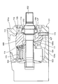
- FIG. 1 is a schematic sectional view of a swash plate type variable displacement hydraulic pump according to a first embodiment of the present invention.
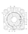
- FIG. 2 is a schematic sectional view taken along the line II-II in FIG.
- FIG. 3 is an enlarged view of a portion in a circle C1 in FIG.
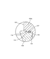
- FIG. 4 is a front view of a swash plate support as a reaction force receiving member.
- FIG. 5 is a side view showing a part of the swash plate support of FIG. 4 in a section in the XX direction.
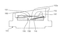
- FIG. 6 is a cross-sectional view for explaining the process of assembling the retaining ring.
- 7 is a cross-sectional view in the YY direction of FIG.
- FIG. 8 is a schematic sectional view of a swash plate type fixed displacement hydraulic pump according to a second embodiment of the present invention.
- FIG. 1 is a schematic view of a cross section of a swash plate type variable displacement hydraulic pump as an example of a hydraulic device according to a first embodiment of the present invention, taken along a plane parallel to the axial direction.
- the swash plate type variable displacement hydraulic pump includes a bottomed cylindrical housing 101, a rotating shaft 102, a cylinder block 103, a plurality of pistons 104, a swash plate 105, and a swash plate support as an example of a reaction force receiving member. And a table 106.
- the housing 101 has a bottom portion 101a and a peripheral side portion 101b which is provided integrally with the bottom portion 101a and is continuous with the peripheral edge portion of the bottom portion 101a.
- An insertion hole 113 for inserting the rotating shaft 102 is provided in the bottom 101a.
- the rotating shaft 102 inserted through the insertion hole 113 is rotatably supported by the housing 101 via a bearing 109.
- a recess 114 into which the swash plate support 106 is fitted is provided inside the bottom 101a of the housing 101. That is, the housing 101 has a concave portion 114 in which the swash plate support 106 is fitted inside the bottom portion 101a.
- a support plate 107 that holds the bearing 109 is fixed to the outer surface of the bottom 101 a of the housing 101 with bolts 108.
- the cylinder block 103 is accommodated in the housing 101 and rotates integrally with the rotary shaft 102.
- the cylinder block 103 is provided with a plurality of cylinder holes 115 extending in the axial direction.
- Each piston 104 is fitted in the cylinder hole 115 so as to be slidable in the axial direction.
- One end of the piston 104 on the swash plate 105 side is provided in a spherical shape, and a shoe 111 is attached to be tiltable.
- the shoe 111 is held by the retainer 311 and rotates together with the cylinder block 103 along the sliding surface 105 a of the swash plate 105 as the cylinder block 103 rotates.
- the piston 104 rotates around the rotation shaft 102 and reciprocates in the cylinder hole 115 as the cylinder block 103 rotates.
- the inclination angle of the sliding surface 105a of the swash plate 105 with respect to the axial direction can be arbitrarily changed by tilting the swash plate 105 with an actuator (not shown).
- an insertion hole 151 through which the rotation shaft 102 is inserted is provided at the center of the swash plate 105.
- the swash plate support 106 as the reaction force receiving member is provided to receive a reaction force received by the swash plate 105 for reciprocating the piston 104, and supports the swash plate 105 so as to be tiltable.
- An insertion hole 161 through which the rotating shaft 102 is inserted is provided at the center of the swash plate support 106.
- the swash plate support 106 is fitted in the recess 114 of the housing 101.
- FIG. 2 is a schematic sectional view taken along the line II-II in FIG.
- FIG. 3 is an enlarged view of a portion surrounded by a circle C1 in FIG.
- a first annular groove 116 is provided on the outer peripheral surface of the swash plate support 106.
- a second annular groove 117 facing the first annular groove 116 is provided on the inner peripheral surface of the recess 114.
- a tapered surface 118 having a diameter that increases as it approaches the swash plate 105 side is provided at the end of the inner peripheral surface of the recess 114 on the swash plate 105 side.
- the swash plate type variable displacement hydraulic pump includes a retaining ring 112 as an example of a wire that engages with the first and second annular grooves 116 and 117.
- the retaining ring 112 has a substantially circular cross section, and the dimension of the circular cross section is the sum of the depth of the first annular groove 116 and the depth of the second annular groove 117.
- the retaining ring 112 and the first and second annular grooves 116 and 117 are closely engaged to prevent rattling.
- the cross-sectional shape of the retaining ring may not be a circular cross section, but may be, for example, a rectangular cross section or a substantially elliptical cross section, and the cross-sectional dimension of the retaining ring is the depth of the first annular groove 116. And the depth of the second annular groove 117 may be smaller. In short, the retaining ring may be engaged with both the first and second annular grooves 116 and 117.
- the retaining ring 112 is made of, for example, metal having flexibility and elasticity, and has a substantially annular shape as shown in FIG. More specifically, the retaining ring 112 has an arc shape of approximately 270 degrees, and a tip 112a is bent inward in the radial direction in an L shape, and the tip 112a is radially inward from the outer peripheral surface of the swash plate support 106. Is engaged with an engagement hole 212 made of a blind hole having a circular cross section. The other portion 112b following the tip 12a of the retaining ring 112 has an arc shape with a central angle of about 270 degrees, and is engaged with the first and second annular grooves 116 and 117 as shown in FIGS. Match.
- the engagement hole 212 is provided at a position overlapping the first annular groove 116 in the circumferential direction of the first annular groove 116. That is, the engagement hole 212 is located at the same position as the first and second annular grooves 116 and 117 in the axial direction of the swash plate support 106.
- the first annular groove 116 is not a complete circle, but is a ring-shaped end with a part missing, and the part with the part missing is a swash plate support as shown in FIG.
- a flat portion 136 is formed on the outer peripheral surface 106, and an engagement hole 212 is provided in the flat portion 136.
- the engagement hole 212 is provided in the flat portion 136, but it may not be provided in the flat portion 136.
- the first annular groove is formed into a complete circle, that is, an endless ring shape, an engagement hole is provided in the first annular groove itself, and a guide for guiding the wire to the first annular groove is provided.
- a groove may be provided.
- a curve G schematically shows the position of the bottom of the second annular groove 117 provided on the inner peripheral surface of the recess 114.
- a notch 131 as an example of an opening is provided on the inner periphery of the housing 101 as shown in FIG. In the state of the finished product shown in FIG. 2, the notch 131 does not face the engagement hole 212, but when the swash plate support 106 is rotated relative to the housing 101, the notch 131 is formed in the engagement hole 212. It is possible to face each other.
- the engaging hole 212 and the front end 112a of the retaining ring 112 can be opposed to each other.
- the swash plate support 106 is pivoted with respect to the housing 101 as shown by an arrow A, and can be assembled in the state shown in FIG.
- a tapered surface 141 connected to one side surface of the notch 131 is provided so that the retaining ring 112 can be smoothly guided by the tapered surface 141 when the retaining ring 112 is assembled.
- the swash plate support 106 is provided with a notch 120 for engagement extending in the radial direction, a screw hole 121 is provided in the housing 101, and the screw hole 121 is provided in the notch 120.
- the tip of a threaded plug 119 is engaged as an example of an engaging member screwed into the engagement. Thereby, the swash plate support 106 is fixed to the housing 101 so as not to rotate.
- the notch 120 is provided at a position overlapping the first annular groove 116 in the circumferential direction of the first annular groove 116. That is, the notch 120 is at the same position as the first and second annular grooves 116 and 117 in the axial direction of the swash plate support 106.
- the retaining ring 112 does not rotate in the rotation direction because the tip 112a is engaged with the engagement hole 212. However, for some reason, the engagement between the tip 112a and the engagement hole 212 is released. Even if the retaining ring 112 tries to rotate, the retaining ring 112 is prevented from rotating because the rear end 112c of the retaining ring 112 contacts the threaded plug 119.
- the threaded plug 119 as an example of the engaging member has a function of fixing the swash plate support 106 to the housing 101 so as not to rotate and a function of preventing the retaining ring 112 from rotating.
- the retaining ring 112 is engaged with the first and second annular grooves 116 and 117 to restrict the axial movement of the swash plate support 106 with respect to the housing 101. Therefore, a conventional mounting bolt can be dispensed with, and a screw hole into which the mounting bolt is screwed does not have to be provided in the bottom surface of the recess 114, so that the processing of the housing 101 is reduced and the housing 101 can be manufactured at low cost. .
- the mounting bolts need not be used, the mounting bolts need not be tightened with a long tool from the opening opposite to the bottom 101a side of the housing 101. Therefore, the swash plate type variable displacement hydraulic pump can be easily assembled.
- the axial length of the assembly composed of the swash plate 105 and the swash plate support 106 can be shortened.
- the mounting bolt can be inserted into the swash plate support 106 and the axial movement of the swash plate support 106 is restricted by the mounting bolt, the head of the mounting bolt comes into contact with the swash plate 105. In order to prevent this, it is necessary to increase the distance between the head of the mounting bolt and the swash plate 105. As a result, the axial length of the assembly composed of the swash plate 105 and the swash plate support 106 becomes long.
- the retaining ring 112 is engaged with the first and second annular grooves 116 and 117 to fix the swash plate support 106 and the housing 101 in the axial direction. The method will be described.
- the engagement hole 212 of the swash plate support 106 is opposed to a notch 131 serving as an opening of the housing 101, and the L-shape of the retaining ring 112 is formed in the engagement hole 212.
- the tip 112a bent in a shape is inserted and engaged.
- the tip 112 a of the retaining ring 112 can be inserted into the engagement hole 212 via the notch (work space) 131. Therefore, the workability of inserting the tip 112a of the retaining ring 112 into the engagement hole 212 is very good.
- the engagement hole 212 is provided in the flat portion 136 outside the first annular groove 116, the engagement hole 212 is easily visible, and the engagement hole 212 and the tip 112a of the retaining ring 112 are provided. Can be easily engaged.
- the retaining ring 112 is wound around the swash plate support 106.
- the retaining ring 112 is wound around the swash plate support 106 in a range of about 270 degrees from the front end 112a to the rear end 112c.
- the swash plate support 106 is turned in the direction of arrow A in FIG.
- the retaining ring 112 is gradually and naturally inserted between the first annular groove 116 and the second annular groove 117 with the leading end 112a bent in an L shape at the top.
- the leading end 112a of the retaining ring 112 bent in an L shape is engaged with the engaging hole 212, so that the leading end 112a of the retaining ring 112 starts with the turning of the swash plate support 106.
- the tip 112a of the retaining ring 112 bent in an L shape engages with the engagement hole 212 and is fixed in the circumferential direction, and the engagement hole 212 and thus the retaining ring 112 are fixed. Since the front end 112a is in a position overlapping the first annular groove 116 in the circumferential direction of the first annular groove 116, the front end 112a of the retaining ring 112 is simply engaged with the engagement hole 212 to support the swash plate. By simply turning the platform 106, the retaining ring 112 can be easily inserted between the first and second annular grooves 116, 117 and engaged with the first and second annular grooves 116, 117. it can.
- the retaining ring 112 when the retaining ring 112 is assembled to the first and second annular grooves 116 and 117, the retaining ring 112 is guided to the tapered surface 141 connected to one side surface of the notch 131 as shown in FIG. 7.
- the retaining ring 112 can be assembled smoothly.
- the notch 131 as an opening in the housing 101 faces the engagement hole 212 before the swash plate support 106 is turned.
- the tip 112a of the retaining ring 112 can be inserted easily.
- the notch 131 provides a space for inserting the tip 112a of the retaining ring 112 into the engagement hole 212, so that the workability of inserting the tip 112a of the retaining ring 112 into the engagement hole 212 is extremely good.
- the opening is the notch 131, the opening can be prevented from being exposed to the outside of the housing 101, and a lid such as a plug can be eliminated from the opening.
- FIG. 8 is a cross-sectional view of a fixed displacement hydraulic pump according to a second embodiment as an example of a hydraulic device.
- the same or similar components as those of the swash plate type variable displacement hydraulic pump of the first embodiment shown in FIG. 1 are denoted by the same reference numerals as those of FIGS.
- FIGS. 1 to 7 and the description thereof are used, the redundant description is omitted, and only different components will be described below.
- the second embodiment is different from the first embodiment only in that the swash plate 105 and the swash plate support 106 of the first embodiment are provided with a dual-purpose member 426 as a reaction force receiving member.
- This dual-purpose member 426 is a reaction force receiving member having a function of a fixed swash plate whose inclination angle cannot be changed.
- a long hole (not shown) as an opening that can face the engagement hole 212 may be provided instead of the notch 131 as the opening of the first embodiment.
- the hydraulic device refers to a device using hydraulic pressure such as a hydraulic device or a hydraulic device, for example, a variable displacement hydraulic pump, a fixed displacement hydraulic pump, a variable displacement hydraulic motor, a fixed displacement. It refers to hydraulic motors.
- the dimension of the retaining ring 112 in the depth direction of the first and second annular grooves 116 and 117 is equal to the depth of the first annular groove 116 and the second annular groove. Although it is substantially equal to the sum of the depth of 117, it may be smaller than the sum. As long as the retaining ring 112 is engaged with the first and second annular grooves 116, 117, the retaining ring 112 may have any size.
- the metal retaining ring 112 is used as the wire, but a rubber or resin retaining ring may be used, for example.
- the first annular groove 116 is an endless circular groove.
- the first annular groove 116 is about 270 to which the retaining ring 112 having a center angle of about 270 degrees shown in FIG. It may be a circular arc-shaped groove.
- annular groove is not limited to an endless circular shape, but an endless circular shape, for example, a substantially arc-shaped groove of about 270 degrees is referred to as an annular groove.
- the engagement hole 212 is provided at a position overlapping the first annular groove 116 in the circumferential direction of the first annular groove 116. You may provide in the position which does not overlap in the circumferential direction. In this case, it is desirable to provide a guide portion such as a guide groove that guides the wire toward the engagement hole.
- the engagement hole 212 is provided in the flat portion 136 outside the first annular groove 116 as shown in FIGS. 4 to 6, but the first annular groove 116 is provided. It may be provided at the position where it intersects itself, that is, the first annular groove 116. In this case, it is desirable to provide a guide groove communicating with the first annular groove 116.
- the tip 112a of the wire 112 is bent in an L shape.
- the tip of the wire is a spherical bulge, and this bulge is used as a bulge. You may engage with an engagement hole.
- the tapered surface 141 that is connected to one side surface of the notch 131 is provided so that the retaining ring 112 can be smoothly guided by the tapered surface 141 when the retaining ring 112 is assembled.
- the tapered surface 141 may not be provided.
Landscapes
- Engineering & Computer Science (AREA)
- Mechanical Engineering (AREA)
- General Engineering & Computer Science (AREA)
- Reciprocating Pumps (AREA)
- Hydraulic Motors (AREA)
Abstract
低コストで製造でき、その上、簡単に組み立てることができる液圧装置が提供される。反力受け部材(106)の外周面には、第1の環状溝(116)が設けられている。また、ハウジング(101)の凹部(114)の内周面には、第1の環状溝(116)に対向する第2の環状溝(117)が設けられている。この第1,第2の環状溝(116,117)には止め輪(112)が係合する。上記反力受け部材(106)には、止め輪(112)のL字状に屈曲した先端(112a)が係合する係合孔(212)が設けられている。
Description
本発明は、例えば、可変容量油圧ポンプ、固定容量油圧ポンプ、可変容量油圧モータ、固定容量油圧モータなどの液圧装置に関する。
従来、液圧装置としては、有底筒形状のハウジング内に配置された斜板支持台を備える油圧ポンプがある(例えば特開平11-351134号公報(特許文献1)参照)。
上記斜板支持台は斜板を傾動可能に支持する。この斜板には、ハウジング内で往復運動するピストンが軸方向において対向する。
また、上記斜板支持台は、ハウジングの底部の内面に設けられた凹部に嵌合する。より詳しくは、上記斜板支持台は、ハウジングの底部側とは反対側の開口からハウジング内に入れられて、上記凹部に嵌合する。そして、上記斜板支持板に設けられた貫通孔に取付ボルトを挿通して締め付けて、斜板支持板の軸方向の移動を規制する。
ところが、上記従来の油圧ポンプでは、斜板支持板の軸方向の移動を取付ボルトで規制するため、凹部の底面にねじ穴を設ける必要がある。
したがって、上記油圧ポンプには、ハウジングの加工が増えて、製造コストが高くなってしまうという問題がある。
また、上記斜板支持板の軸方向の移動を取付ボルトで規制する場合、長い工具を使用し、ハウジングの底部側とは反対側の開口から取付ボルトを締め付けることになる。
したがって、上記油圧ポンプには、取付ボルトの締め付けに長い工具が必要になり、組み立てが煩わしいという問題もある。
そこで、本発明の課題は、低コストで製造でき、その上、簡単に組み立てることができる液圧装置を提供することにある。
上記課題を解決するため、本発明の液圧装置は、
有底筒形状のハウジングと、
上記ハウジング内に回転可能に設けられた回転軸と、
上記ハウジング内において上記回転軸周りに回転可能に設けられ、上記回転軸周りの回転に伴って往復運動する複数のピストンを有するシリンダブロックと、
上記ハウジング内に収容され、上記ピストンを往復運動させるための反力を受けるための反力受け部材と
を備え、
上記ハウジングは、上記反力受け部材が嵌合する凹部を底部の内側に有し、
上記反力受け部材の外周面には、第1の環状溝が設けられ、
上記凹部の内周面には、上記第1の環状溝に対向する第2の環状溝が設けられ、
上記第1,第2の環状溝には線材が係合し、
上記反力受け部材は、上記線材の先端が係合する係合孔を有する
ことを特徴としている。
有底筒形状のハウジングと、
上記ハウジング内に回転可能に設けられた回転軸と、
上記ハウジング内において上記回転軸周りに回転可能に設けられ、上記回転軸周りの回転に伴って往復運動する複数のピストンを有するシリンダブロックと、
上記ハウジング内に収容され、上記ピストンを往復運動させるための反力を受けるための反力受け部材と
を備え、
上記ハウジングは、上記反力受け部材が嵌合する凹部を底部の内側に有し、
上記反力受け部材の外周面には、第1の環状溝が設けられ、
上記凹部の内周面には、上記第1の環状溝に対向する第2の環状溝が設けられ、
上記第1,第2の環状溝には線材が係合し、
上記反力受け部材は、上記線材の先端が係合する係合孔を有する
ことを特徴としている。
ここで、「反力受け部材」とは、例えば、斜板が受ける反力を支える部材などを指す。
また、この明細書では、環状溝とは、無端の円形に限らず、有端の円形、例えば、略270度の略円弧状の溝であっても、環状溝と言う。
上記構成によれば、上記線材が第1および第2の環状溝に係合することにより、例えば、取付ボルトを用いずに、反力受け部材の軸方向の移動を規制できる。したがって、上記凹部にねじ穴を設けずに済むので、ハウジングの加工が減って、低コストで製造できる。
また、上記取付ボルトを用いなくてもよいので、上記従来の油圧ポンプの組立時に使用した長い工具も用いなくてもよく、簡単に組み立てることができる。
また、上記反力受け部材は、上記線材の先端が係合する係合孔を有するので、上記線材の先端を係合孔に係合させた状態で、反力受け部材をハウジングに対して旋回させることによって、上記線材を第1および第2の環状溝に簡単の係合させることができる。
一実施形態の液圧装置では、
上記係合孔は、上記第1の環状溝の円周方向において、上記第1の環状溝と重なる位置に設けられている。
上記係合孔は、上記第1の環状溝の円周方向において、上記第1の環状溝と重なる位置に設けられている。
上記実施形態によれば、上記係合孔は、上記第1の環状溝の円周方向において、上記第1の環状溝と重なる位置に設けられているから、上記係合孔に線材の先端を係合して、反力受け部材をハウジングに対して旋回させるだけで、簡単に、線材を第1および第2の環状溝の間に、しごくようにして挿入して、第1および第2の環状溝に係合することができる。
一実施形態の液圧装置では、
上記係合孔は、上記第1の環状溝の外側の平坦部に設けられている。
上記係合孔は、上記第1の環状溝の外側の平坦部に設けられている。
上記実施形態では、上記係合孔が上記第1の環状溝の外側の平坦部に設けられているから、係合孔の視認が容易であって、係合孔と線材の先端との係合を容易にできる。
一実施形態の液圧装置では、
上記線材の先端は、L字形状に屈曲している。
上記線材の先端は、L字形状に屈曲している。
上記実施形態によれば、上記線材の先端がL字形状に屈曲しているから、簡単に、そのL字形状に屈曲した線材の先端を係合孔に挿入して、第1の環状溝の周方向に係合することができる。
一実施形態の液圧装置では、
上記ハウジングは、上記反力受け部材を上記ハウジングに対して相対的に回転させると、上記係合孔に対向可能な開口を有する。
上記ハウジングは、上記反力受け部材を上記ハウジングに対して相対的に回転させると、上記係合孔に対向可能な開口を有する。
上記実施形態によれば、上記ハウジングが、上記反力受け部材を上記ハウジングに対して相対的に回転させると、上記係合孔に対向可能な開口を有するから、上記反力受け部材を旋回させる前の状態で、上記開口に係合孔を対向させて、この開口を経由して、線材の先端を係合孔に挿入できる。したがって、線材の先端を係合孔に挿入する作業性が極めて良い。
一実施形態の液圧装置では、
上記開口は、切欠きである。
上記開口は、切欠きである。
上記実施形態によれば、上記開口が切欠きであるから、ハウジングの外側に開口が露出しないようにできて、開口にプラグなどの蓋を不要とすることができる。
一実施形態の液圧装置では、
上記切欠きの一側面に連なるテーパ面を有する。
上記切欠きの一側面に連なるテーパ面を有する。
上記実施形態によれば、上記線材の第1および第2の環状溝への組み付け時に、上記線材が切欠きの一側面に連なるテーパ面に案内されるので、線材を第1および第2の環状溝へスムーズに組み付けることができる。
一実施形態の液圧装置では、
上記ハウジングと上記反力受け部材とに周方向に係合する係合部材を有する。
上記ハウジングと上記反力受け部材とに周方向に係合する係合部材を有する。
上記実施形態によれば、上記係合部材が、上記ハウジングと上記反力受け部材とに周方向に係合するから、上記反力受け部材はハウジングに対して回転不可に固定される。
一実施形態の液圧装置では、
上記係合部材は、上記第1の環状溝の周方向に、上記線材に重なる位置に設けられている。
上記係合部材は、上記第1の環状溝の周方向に、上記線材に重なる位置に設けられている。
上記実施形態によれば、上記係合部材は、上記第1の環状溝の周方向に、上記線材に重なる位置に設けられているから、上記線材の周方向の移動を規制し、つまり、線材の回転を阻止することができる。
したがって、上記係合部材は、反力受け部材をハウジングに対して回転不可に固定する機能と、線材の回転を阻止する機能とを有する。
一実施形態の液圧装置では、
上記第1および第2の環状溝の深さ方向の上記線材の寸法は、上記第1の環状溝の深さと上記第2の環状溝の深さとの和に略等しい。
上記第1および第2の環状溝の深さ方向の上記線材の寸法は、上記第1の環状溝の深さと上記第2の環状溝の深さとの和に略等しい。
上記実施形態によれば、上記第1および第2の環状溝の深さ方向の上記線材の寸法が、上記第1の環状溝の深さと上記第2の環状溝の深さとの和に略等しいので、線材と第1,第2の環状溝116,117とが密に係合して、がたつかないと言う利点を有する。
本発明の液圧装置によれば、反力受け部材の周面には、第1の環状溝が設けられ、凹部の内周面には、第1の環状溝に対向する第2の環状溝が設けられ、第1,第2の環状溝のそれぞれには線材が係合するので、例えば取付ボルトを使用しなくても、反力受け部材の軸方向の移動を規制できる。したがって、上記反力受け部材を嵌合させる凹部にねじ穴を設けずに済むので、ハウジングの加工が減って、低コストで製造できる。
また、上記取付ボルトを使用しなくてもよいので、上記従来の油圧ポンプの組立時に使用した長い工具も用いなくてもよく、簡単に組み立てることができる。
また、上記反力受け部材は、上記線材の先端が係合する係合孔を有するので、上記線材の先端を係合孔に係合させた状態で、反力受け部材をハウジングに対して旋回させることによって、上記線材を第1および第2の環状溝に簡単の係合させることができる。
以下、本発明の液圧装置を図示の実施の形態により詳細に説明する。
(第1実施形態)
図1は、本発明の第1実施形態の液圧装置の一例としての斜板式可変容量油圧ポンプを軸方向に平行な面で切った断面の概略図である。
図1は、本発明の第1実施形態の液圧装置の一例としての斜板式可変容量油圧ポンプを軸方向に平行な面で切った断面の概略図である。
上記斜板式可変容量油圧ポンプは、有底筒形状のハウジング101と、回転軸102と、シリンダブロック103と、複数のピストン104と、斜板105と、反力受け部材の一例としての斜板支持台106とを備える。
上記ハウジング101は、底部101aと、この底部101aと一体に設けられ、底部101aの周縁部に連なる周側部101bとを有している。この底部101aには、回転軸102を挿通するための挿通孔113が設けられている。この挿通孔113に挿通された回転軸102は、ハウジング101にベアリング109を介して回転自在に支持されている。
また、上記ハウジング101の底部101aの内側には、斜板支持台106が嵌合する凹部114が設けられている。すなわち、ハウジング101は、斜板支持台106が嵌合する凹部114を底部101aの内側に有している。
一方、上記ハウジング101の底部101aの外面には、ベアリング109を押さえる支持プレート107がボルト108で固定されている。
上記シリンダブロック103は、ハウジング101内に収容され、回転軸102と一体に回転する。このシリンダブロック103には、軸方向に延びるシリンダ穴115が複数設けられている。
上記各ピストン104は、シリンダ穴115内に軸方向に摺動自在に嵌合されている。このピストン104の斜板105側の一端部は、球状に設けられ、シュー111が傾動可能に取り付けられている。このシュー111は、リテーナ311に保持されて、シリンダブロック103の回転に伴い、斜板105の摺動面105aに沿ってシリンダブロック103と共に旋回する。
これにより、ピストン104は、シリンダブロック103の回転に伴い、回転軸102の周りを回転すると共に、シリンダ穴115内を往復運動する。
上記斜板105の摺動面105aの軸方向に対する傾斜角を、図示しないアクチュエータで斜板105を傾動させて、任意に変更できるようになっている。また、斜板105の中央部には、回転軸102が挿通される挿通孔151が設けられている。
上記反力受け部材としての斜板支持台106は、ピストン104を往復運動させるために斜板105が受ける反力を受けるために設けられ、斜板105を傾動可能に支持している。この斜板支持台106の中央部には、回転軸102が挿通される挿通孔161が設けられている。また、斜板支持台106はハウジング101の凹部114に嵌合している。
図2は図1のII-II線矢視の概略断面図である。また、図3は、図1の円C1で囲んだ部分の拡大図である。
上記斜板支持台106の外周面には、図2および図3に示すように、第1の環状溝116が設けられている。一方、上記凹部114の内周面には、第1の環状溝116に対向する第2の環状溝117が設けられている。また、上記凹部114の内周面における斜板105側の端部には、斜板105側に近づくにしたがって径が大きくなるテーパ面118が設けられている。
また、上記斜板式可変容量油圧ポンプは、第1および第2の環状溝116,117に係合する線材の一例としての止め輪112を備える。図3に示すように、上記止め輪112の断面は、略円形断面であって、この円形断面の寸法は、第1の環状溝116の深さと第2の環状溝117の深さとの和に略等しくなっていて、止め輪112と第1および第2の環状溝116,117とが密に係合して、がたつかないようにしている。
なお、図示しないが、止め輪の断面形状は、円形断面でなくて、例えば、矩形断面、略楕円断面であってもよく、また、止め輪の断面寸法は、第1の環状溝116の深さと第2の環状溝117の深さとの和よりも小さくてもよい。要は、止め輪が、第1および第2の環状溝116,117の両方に係合すればよい。
上記止め輪112は、可撓性および弾性を有する例えば金属製であり、図2に示すように、略環状をしている。より詳しくは、上記止め輪112は、略270度の円弧状で、先端112aがL字状に半径方向内側に屈曲し、この先端112aが、斜板支持台106の外周面から半径方向の内側に延びる断面円形の盲孔からなる係合孔212に係合している。この止め輪112の先端12aに続く他の部分112bは、中心角が略270度の円弧状であって、図2および3に示すように、第1,第2の環状溝116,117に係合している。
図4に示すように、上記係合孔212は、第1の環状溝116の円周方向において、その第1の環状溝116と重なる位置に設けられている。すなわち、上記係合孔212は、第1および第2の環状溝116,117とは、斜板支持台106の軸方向において、同じ位置にある。
上記第1の環状溝116は、完全な円形ではなくて、一部が欠けた有端のリング状であって、この一部が欠けた部分が、図5に示すように、斜板支持台106の外周面における平坦部136になっていて、この平坦部136に係合孔212が設けられている。
なお、この第1実施形態では、係合孔212が平坦部136に設けられているが、平坦部136に設けなくてもよい。例えば、図示しないが、第1の環状溝を完全な円形、つまり、無端のリング形状に形成し、この第1の環状溝自体に係合孔を設け、第1の環状溝に線材を導く案内溝を設けてもよい。
図5において、曲線Gは、凹部114の内周面に設けられた第2の環状溝117の底の位置を模式的に示すものである。
一方、上記ハウジング101の内周に、図2に示すように、開口の一例としての切欠き131を設けている。この切欠き131は、図2に示す完成品の状態では、係合孔212に対向していないが、斜板支持台106をハウジング101に対して相対的に回転させると、係合孔212に対向可能になっている。
すなわち、図6に示す止め輪112の組み付けが完成する前の状態では、係合孔212および止め輪112の先端112aに対向できるようになっている。そして、図6において、斜板支持台106をハウジング101に対して矢印Aに示すように旋回させて、図2に示す状態に組み付けができるようになっている。
また、図7に示すように、上記切欠き131の一側面に連なるテーパ面141設けて、このテーパ面141で、止め輪112の組み付け時に、止め輪112をスムーズに案内できるようにしている。
一方、図2に示すように、上記斜板支持台106には、半径方向に延びる係合用の切欠き120を設け、ハウジング101にネジ穴121を設けて、この切欠き120に、ネジ穴121に螺合した係合部材の一例としてのネジ付プラグ119の先端が係合している。これにより、斜板支持台106はハウジング101に対して回転不可に固定される。
上記切欠き120は、第1の環状溝116の円周方向において、その第1の環状溝116と重なる位置に設けられている。すなわち、上記切欠き120は、第1および第2の環状溝116,117とは、斜板支持台106の軸方向において、同じ位置にある。
こうすることによって、図2において、止め輪112が時計回り方向に移動しようとすると、止め輪112の後端112cがネジ付プラグ119に当接して、止め輪112の脱落が防止される。
本来、止め輪112は、先端112aが係合孔212に係合しているから、回転方向に回ることは無いが、もし、何らかの理由で、先端112aと係合孔212との係合が外れて、止め輪112が回転しょうとしても、止め輪112の後端112cがネジ付プラグ119に当接するから、止め輪112の回転が阻止される。
このように、上記係合部材の一例としてのネジ付プラグ119は、斜板支持台106をハウジング101に対して回転不可に固定する機能と、止め輪112の回転を阻止する機能とを有する。
上記構成の斜板式可変容量油圧ポンプによれば、上記止め輪112が第1,第2の環状溝116,117に係合して、斜板支持台106のハウジング101に対する軸方向の移動を規制するので、従来のような取付ボルトを不要とでき、また、上記取付ボルトが螺合するねじ穴を凹部114の底面に設けずに済むので、ハウジング101の加工が減って、低コストで製造できる。
また、上記取付ボルトを用いなくてもよいので、ハウジング101の底部101a側とは反対側の開口から取付ボルトを長い工具で締め付けなくてもよい。したがって、上記斜板式可変容量油圧ポンプは簡単に組み立てることができる。
また、上記取付ボルトを用いずに、斜板支持台106の軸方向の移動を規制するので、斜板105と斜板支持台106からなるアッセンブリの軸方向の長さを短くすることができる。
仮に、上記斜板支持台106に取付ボルトを挿通できるようにして、この取付ボルトによって斜板支持台106の軸方向の移動を規制したなら、取付ボルトの頭部が斜板105に接触するのを防ぐため、取付ボルトの頭部と斜板105との間の距離を大きくとる必要がある。その結果、斜板105と斜板支持台106からなるアッセンブリの軸方向の長さが長くなってしまう。
次に、上記構成の斜板式可変容量油圧ポンプにおいて、止め輪112を第1,第2の環状溝116,117に係合して、斜板支持台106とハウジング101とを軸方向に固定する方法について、説明する。
まず、図6および7に示すように、上記斜板支持台106の係合孔212を、ハウジング101の開口としての切欠き131に対向させ、この係合孔212に、止め輪112のL字状に屈曲した先端112aを挿入して係合する。
このとき、上記係合孔212に開口としての切欠き131が対向しているから、この切欠き(作業空間)131を経由して、止め輪112の先端112aを係合孔212に挿入できる。したがって、止め輪112の先端112aを係合孔212に挿入する作業性が極めて良い。
さらに、上記係合孔212が第1の環状溝116の外側の平坦部136に設けられているから、係合孔212の視認が容易であって、係合孔212と止め輪112の先端112aとの係合を容易にできる。
そして、上記止め輪112の先端112aに続く部分112bをハウジング101のテーパ面141に沿わせた後、止め輪112を斜板支持台106の回りに巻回する。このとき、図6に示すように、止め輪112は、先端112aから後端112cまで、斜板支持台106の回りを約270度の範囲で巻回している。
次に、上記斜板支持台106を図6において矢印Aの方向に旋回する。そうすると、止め輪112は、L字状に屈曲した先端112aを先頭にして、第1の環状溝116と第2の環状溝117との間に自然に徐々に挿入されていく。このように、止め輪112が、L字状に屈曲した先端112aが係合孔212に係合されているから、斜板支持台106の旋回に伴って、止め輪112の先端112aを先頭にして、しごかれたように、第1の環状溝116と第2の環状溝117との間に自然に入っていくのは、係合孔212、ひいては、止め輪112の先端112aが、第1の環状溝116の周方向に、第1の環状溝116と重なる位置にあるからである。こうして、上記斜板支持台106が約270度旋回すると、図2に示す状態になる。このとき、上記止め輪112は第1および第2の環状溝116,117の両者に係合している。
この第1実施形態では、上記止め輪112のL字状に屈曲した先端112aが係合孔212に係合して周方向に固定され、かつ、上記係合孔212、ひいては、止め輪112の先端112aが、第1の環状溝116の周方向に、第1の環状溝116と重なる位置にあるから、単に、止め輪112の先端112aを係合孔212に係合して、斜板支持台106を旋回させるだけで、簡単に、止め輪112を第1および第2の環状溝116,117の間に挿入して、第1および第2の環状溝116,117に係合させることができる。
また、上記止め輪112の第1および第2の環状溝116,117への組み付け時に、図7に示すように、止め輪112が切欠き131の一側面に連なるテーパ面141に案内されるので、止め輪112をスムーズに組み付けることができる。
また、図6に示すように、上記ハウジング101に開口としての切欠き131が、斜板支持台106を旋回させる前の状態では、係合孔212に対向しているから、この係合孔212に止め輪112の先端112aを容易に挿入することができる。すなわち、切欠き131によって、止め輪112の先端112aを係合孔212に挿入するための空間ができているから、止め輪112の先端112aを係合孔212に挿入する作業性が極めて良い。
また、上記開口が切欠き131であるから、ハウジング101の外側に開口が露出しないようにできて、開口にプラグなどの蓋を不要とすることができる。
(第2実施形態)
図8は、液圧装置の一例としての第2実施形態の固定容量油圧ポンプの断面図である。図8において、図1に示す第1実施形態の斜板式可変容量油圧ポンプの構成部と同一または類似の構成部については、図1~7の構成部と同一参照番号を付して、それらの構成および作用については、図1~7およびその説明を援用し、重複する説明を省略し、異なる構成部のみについて、以下に説明する。
図8は、液圧装置の一例としての第2実施形態の固定容量油圧ポンプの断面図である。図8において、図1に示す第1実施形態の斜板式可変容量油圧ポンプの構成部と同一または類似の構成部については、図1~7の構成部と同一参照番号を付して、それらの構成および作用については、図1~7およびその説明を援用し、重複する説明を省略し、異なる構成部のみについて、以下に説明する。
この第2実施形態は、第1実施形態の斜板105と斜板支持台106とが一体になった反力受け部材としての兼用部材426を備える点のみが、第1実施形態と異なる。
この兼用部材426は、反力受け部材に、傾斜角を変えることができない固定斜板の機能を持たせたものである。
これ以外の作用、効果は、第1実施形態と同様であるので、その説明は省略する。
なお、この第2実施形態では、第1実施形態の開口としての切欠き131に代えて、係合孔212に対向し得る開口としての図示しない長穴を設けてもよい。
本明細書で液圧装置とは、油圧装置や水圧装置等の液圧を使用する装置のことを言い、例えば、可変容量液圧ポンプ、固定容量液圧ポンプ、可変容量液圧モータ、固定容量液圧モータなどのことを言う。
また、上記第1および第2実施形態では、上記第1および第2の環状溝116,117の深さ方向の止め輪112の寸法は、第1の環状溝116の深さと第2の環状溝117の深さとの和に略等しくしているが、その和よりも小さくしてもよい。止め輪112と、第1および第2の環状溝116,117とが係合さえすれば、止め輪112の寸法はどのようなものであってもよい。
上記第1および第2実施形態では、線材として金属製の止め輪112を用いていたが、例えばゴム製または樹脂製の止め輪を用いてもよい。
また、上記第1実施形態では、第1の環状溝116は、無端の円形の溝であったが、例えば、図2に示す中心角が約270度の止め輪112が入る程度の、約270度の円弧状の溝であってもよい。
なお、この明細書では、環状溝とは、無端の円形に限らず、有端の円形、例えば、略270度の略円弧状の溝であっても、環状溝と言う。
上記第1および第2実施形態では、係合孔212は、第1の環状溝116の円周方向において、その第1の環状溝116に重なる位置に設けていたが、第1の環状溝の円周方向に重ならない位置に設けてもよい。この場合、線材を係合孔に向けて案内するガイド溝などのガイド部を設けるのが望ましい。
また、上記第1および第2実施形態では、係合孔212は、図4~6に示すように、第1の環状溝116の外部の平坦部136に設けたが、第1の環状溝116自体、つまり、第1の環状溝116と交わる位置に設けてもよい。この場合、第1の環状溝116に連通する案内溝を設けるのが望ましい。
また、上記第1および第2実施形態では、上記線材112の先端112aは、L字形状に屈曲していたが、それに代えて、線材の先端を球状の膨出部とし、この膨出部を係合孔に係合させてもよい。
また、上記第1実施形態では、上記切欠き131の一側面に連なるテーパ面141設けて、このテーパ面141で、止め輪112の組み付け時に、止め輪112をスムーズに案内できるようにしているが、テーパ面141は設け無くてもよい。
第1および第2実施形態および変形例で述べた構成要素は、適宜、組み合わせてもよく、また、適宜、選択、置換、あるいは、削除してもよいのは、勿論である。
101 ハウジング
102 回転軸
104 ピストン
105 斜板
106 斜板支持台
112 止め輪
112a 先端
114 凹部
116 第1の環状溝
117 第2の環状溝
119 プラグ
121 係合部材
212 係合孔
136 平坦部
141 テーパ面
426 兼用部材
102 回転軸
104 ピストン
105 斜板
106 斜板支持台
112 止め輪
112a 先端
114 凹部
116 第1の環状溝
117 第2の環状溝
119 プラグ
121 係合部材
212 係合孔
136 平坦部
141 テーパ面
426 兼用部材
Claims (10)
- 有底筒形状のハウジング(101)と、
上記ハウジング(101)内に回転可能に設けられた回転軸(102)と、
上記ハウジング(101)内において上記回転軸(102)周りに回転可能に設けられ、上記回転軸(102)周りの回転に伴って往復運動する複数のピストン(104)を有するシリンダブロック(103)と、
上記ハウジング(101)内に収容され、上記ピストン(104)を往復運動させるための反力を受けるための反力受け部材(106,426)と
を備え、
上記ハウジング(101)は、上記反力受け部材(106,426)が嵌合する凹部(114)を底部(101a)の内側に有し、
上記反力受け部材(106,426)の外周面には、第1の環状溝(116)が設けられ、
上記凹部(114)の内周面には、上記第1の環状溝(116)に対向する第2の環状溝(117)が設けられ、
上記第1,第2の環状溝(116,117)には線材(112)が係合し、
上記反力受け部材(106,426)は、上記線材(112)の先端が係合する係合孔(212)を有する
ことを特徴とする液圧装置。 - 請求項1に記載の液圧装置において、
上記係合孔(212)は、上記第1の環状溝(116)の円周方向において、上記第1の環状溝(116)と重なる位置に設けられていることを特徴とする液圧装置。 - 請求項2に記載の液圧装置において、
上記係合孔(212)は、上記第1の環状溝(116)の外側の平坦部(136)に設けられていることを特徴とする液圧装置。 - 請求項1から3までの何れか1つに記載の液圧装置において、
上記線材(112)の先端(112a)は、L字形状に屈曲していることを特徴とする液圧装置。 - 請求項1から4までの何れか1つに記載の液圧装置において、
上記ハウジング(101)は、上記反力受け部材(106,426)を上記ハウジング(101)に対して相対的に回転させると、上記係合孔(212)に対向可能な開口(131)を有することを特徴とする液圧装置。 - 請求項5に記載の液圧装置において、
上記開口(131)は、切欠き(131)であることを特徴とする液圧装置。 - 請求項6に記載の液圧装置において、
上記切欠き(131)の一側面に連なるテーパ面(141)を有することを特徴とする液圧装置。 - 請求項1から7までの何れか1つに記載の液圧装置において、
上記ハウジング(101)と上記反力受け部材(106,426)とに係合する係合部材(119)を有することを特徴とする液圧装置。 - 請求項8に記載の液圧装置において、
上記係合部材(119)は、上記第1の環状溝(116)の周方向に、上記線材(112)に重なる位置に設けられていることを特徴とする液圧装置。 - 請求項1から9までの何れか1つに記載の液圧装置において、
上記第1および第2の環状溝(116,117)の深さ方向の上記線材(112)の寸法は、上記第1の環状溝(116)の深さと上記第2の環状溝(117)の深さとの和に略等しいことを特徴とする液圧装置。
Priority Applications (1)
| Application Number | Priority Date | Filing Date | Title |
|---|---|---|---|
| CN201580062096.7A CN107002632B (zh) | 2014-12-09 | 2015-08-24 | 液压装置 |
Applications Claiming Priority (2)
| Application Number | Priority Date | Filing Date | Title |
|---|---|---|---|
| JP2014-248815 | 2014-12-09 | ||
| JP2014248815A JP5858131B1 (ja) | 2014-12-09 | 2014-12-09 | 液圧装置 |
Publications (1)
| Publication Number | Publication Date |
|---|---|
| WO2016092908A1 true WO2016092908A1 (ja) | 2016-06-16 |
Family
ID=55300987
Family Applications (1)
| Application Number | Title | Priority Date | Filing Date |
|---|---|---|---|
| PCT/JP2015/073732 Ceased WO2016092908A1 (ja) | 2014-12-09 | 2015-08-24 | 液圧装置 |
Country Status (3)
| Country | Link |
|---|---|
| JP (1) | JP5858131B1 (ja) |
| CN (1) | CN107002632B (ja) |
| WO (1) | WO2016092908A1 (ja) |
Citations (3)
| Publication number | Priority date | Publication date | Assignee | Title |
|---|---|---|---|---|
| JPS54329A (en) * | 1978-05-25 | 1979-01-05 | Teijin Seiki Co Ltd | Hydraulic drive for caterpillar tractor |
| JPH11236872A (ja) * | 1998-02-24 | 1999-08-31 | Komatsu Ltd | 油圧ポンプ・モータの回転状態検出装置 |
| US6287086B1 (en) * | 2000-02-23 | 2001-09-11 | Eaton Corporation | Hydraulic pump with ball joint shaft support |
Family Cites Families (3)
| Publication number | Priority date | Publication date | Assignee | Title |
|---|---|---|---|---|
| JPH11351134A (ja) * | 1998-06-12 | 1999-12-21 | Hitachi Constr Mach Co Ltd | 可変容量型斜板式油圧ポンプ |
| JP3718080B2 (ja) * | 1999-05-07 | 2005-11-16 | 日立建機株式会社 | ブレーキ装置を有する液圧モータ |
| DE102010006908A1 (de) * | 2010-02-05 | 2011-08-11 | Robert Bosch GmbH, 70469 | Axialkolbenmaschine in Schrägscheibenbauweise |
-
2014
- 2014-12-09 JP JP2014248815A patent/JP5858131B1/ja active Active
-
2015
- 2015-08-24 WO PCT/JP2015/073732 patent/WO2016092908A1/ja not_active Ceased
- 2015-08-24 CN CN201580062096.7A patent/CN107002632B/zh active Active
Patent Citations (3)
| Publication number | Priority date | Publication date | Assignee | Title |
|---|---|---|---|---|
| JPS54329A (en) * | 1978-05-25 | 1979-01-05 | Teijin Seiki Co Ltd | Hydraulic drive for caterpillar tractor |
| JPH11236872A (ja) * | 1998-02-24 | 1999-08-31 | Komatsu Ltd | 油圧ポンプ・モータの回転状態検出装置 |
| US6287086B1 (en) * | 2000-02-23 | 2001-09-11 | Eaton Corporation | Hydraulic pump with ball joint shaft support |
Also Published As
| Publication number | Publication date |
|---|---|
| CN107002632A (zh) | 2017-08-01 |
| JP5858131B1 (ja) | 2016-02-10 |
| CN107002632B (zh) | 2018-06-26 |
| JP2016109075A (ja) | 2016-06-20 |
Similar Documents
| Publication | Publication Date | Title |
|---|---|---|
| US11904933B2 (en) | Steering column for vehicle | |
| KR102543379B1 (ko) | 전기 유압식 서보 브레이크의 통합형 유압 모듈 | |
| US10500984B2 (en) | Reduction gear and gear motor | |
| JP5232780B2 (ja) | リテーナディスク上に追加ディスクを有するアキシアルピストン装置、対応のリテーナディスク及び対応の追加ディスク | |
| KR20100045906A (ko) | 공작기계용 분할 장치에서의 클램프 장치 | |
| WO2013153684A1 (ja) | 斜軸式アキシャルピストンポンプ・モータ | |
| JP2012203030A (ja) | レンズ鏡筒及び光学機器 | |
| JP2019516895A (ja) | 油圧装置 | |
| US20170058904A1 (en) | Fluid driving device, motor assembly and centrifugal friction clutch thereof | |
| JP5858131B1 (ja) | 液圧装置 | |
| US10012219B2 (en) | Hydrostatic variable displacement axial piston machine, in particular hydrostatic variable displacement axial piston motor | |
| US11187302B2 (en) | Reduction gear and gear motor | |
| KR101697854B1 (ko) | 감속기의 베어링 예압 기구 | |
| US10598326B2 (en) | Universal type mounting structure for car lamp bulb and method for assembling universal type mounting structure for car lamp bulb with bulb | |
| JP5682687B1 (ja) | 液圧装置 | |
| JP6761356B2 (ja) | 動翼可変軸流ファンの芯出治具及び芯出方法 | |
| JP6124975B2 (ja) | 軸受 | |
| EP1975406B1 (en) | Plunger-slipper assembly of high-pressure pump | |
| JP2007009801A (ja) | 油圧モータ | |
| JP4506211B2 (ja) | 摺動機構 | |
| JP2017510767A (ja) | 軸受ユニット | |
| CN102878149B (zh) | 密封件安装结构及密封件安装方法 | |
| JP5382294B2 (ja) | ホース用継手金具のカシメ装置 | |
| JP6505666B2 (ja) | 動力伝達装置 | |
| JP2019119024A (ja) | 支持装置 |
Legal Events
| Date | Code | Title | Description |
|---|---|---|---|
| 121 | Ep: the epo has been informed by wipo that ep was designated in this application |
Ref document number: 15867843 Country of ref document: EP Kind code of ref document: A1 |
|
| NENP | Non-entry into the national phase |
Ref country code: DE |
|
| 122 | Ep: pct application non-entry in european phase |
Ref document number: 15867843 Country of ref document: EP Kind code of ref document: A1 |