WO2016088331A1 - 制御装置 - Google Patents
制御装置 Download PDFInfo
- Publication number
- WO2016088331A1 WO2016088331A1 PCT/JP2015/005828 JP2015005828W WO2016088331A1 WO 2016088331 A1 WO2016088331 A1 WO 2016088331A1 JP 2015005828 W JP2015005828 W JP 2015005828W WO 2016088331 A1 WO2016088331 A1 WO 2016088331A1
- Authority
- WO
- WIPO (PCT)
- Prior art keywords
- state
- switching
- motor
- control device
- lift amount
- Prior art date
- Legal status (The legal status is an assumption and is not a legal conclusion. Google has not performed a legal analysis and makes no representation as to the accuracy of the status listed.)
- Ceased
Links
Images





Classifications
-
- F—MECHANICAL ENGINEERING; LIGHTING; HEATING; WEAPONS; BLASTING
- F01—MACHINES OR ENGINES IN GENERAL; ENGINE PLANTS IN GENERAL; STEAM ENGINES
- F01L—CYCLICALLY OPERATING VALVES FOR MACHINES OR ENGINES
- F01L1/00—Valve-gear or valve arrangements, e.g. lift-valve gear
- F01L1/02—Valve drive
- F01L1/04—Valve drive by means of cams, camshafts, cam discs, eccentrics or the like
- F01L1/08—Shape of cams
-
- F—MECHANICAL ENGINEERING; LIGHTING; HEATING; WEAPONS; BLASTING
- F01—MACHINES OR ENGINES IN GENERAL; ENGINE PLANTS IN GENERAL; STEAM ENGINES
- F01L—CYCLICALLY OPERATING VALVES FOR MACHINES OR ENGINES
- F01L9/00—Valve-gear or valve arrangements actuated non-mechanically
- F01L9/20—Valve-gear or valve arrangements actuated non-mechanically by electric means
-
- F—MECHANICAL ENGINEERING; LIGHTING; HEATING; WEAPONS; BLASTING
- F01—MACHINES OR ENGINES IN GENERAL; ENGINE PLANTS IN GENERAL; STEAM ENGINES
- F01L—CYCLICALLY OPERATING VALVES FOR MACHINES OR ENGINES
- F01L9/00—Valve-gear or valve arrangements actuated non-mechanically
- F01L9/20—Valve-gear or valve arrangements actuated non-mechanically by electric means
- F01L9/22—Valve-gear or valve arrangements actuated non-mechanically by electric means actuated by rotary motors
-
- F—MECHANICAL ENGINEERING; LIGHTING; HEATING; WEAPONS; BLASTING
- F02—COMBUSTION ENGINES; HOT-GAS OR COMBUSTION-PRODUCT ENGINE PLANTS
- F02D—CONTROLLING COMBUSTION ENGINES
- F02D13/00—Controlling the engine output power by varying inlet or exhaust valve operating characteristics, e.g. timing
- F02D13/02—Controlling the engine output power by varying inlet or exhaust valve operating characteristics, e.g. timing during engine operation
- F02D13/0203—Variable control of intake and exhaust valves
- F02D13/0207—Variable control of intake and exhaust valves changing valve lift or valve lift and timing
-
- F—MECHANICAL ENGINEERING; LIGHTING; HEATING; WEAPONS; BLASTING
- F02—COMBUSTION ENGINES; HOT-GAS OR COMBUSTION-PRODUCT ENGINE PLANTS
- F02D—CONTROLLING COMBUSTION ENGINES
- F02D41/00—Electrical control of supply of combustible mixture or its constituents
- F02D41/20—Output circuits, e.g. for controlling currents in command coils
-
- F—MECHANICAL ENGINEERING; LIGHTING; HEATING; WEAPONS; BLASTING
- F01—MACHINES OR ENGINES IN GENERAL; ENGINE PLANTS IN GENERAL; STEAM ENGINES
- F01L—CYCLICALLY OPERATING VALVES FOR MACHINES OR ENGINES
- F01L2820/00—Details on specific features characterising valve gear arrangements
- F01L2820/03—Auxiliary actuators
- F01L2820/032—Electric motors
-
- F—MECHANICAL ENGINEERING; LIGHTING; HEATING; WEAPONS; BLASTING
- F02—COMBUSTION ENGINES; HOT-GAS OR COMBUSTION-PRODUCT ENGINE PLANTS
- F02D—CONTROLLING COMBUSTION ENGINES
- F02D41/00—Electrical control of supply of combustible mixture or its constituents
- F02D41/0002—Controlling intake air
- F02D2041/001—Controlling intake air for engines with variable valve actuation
-
- Y—GENERAL TAGGING OF NEW TECHNOLOGICAL DEVELOPMENTS; GENERAL TAGGING OF CROSS-SECTIONAL TECHNOLOGIES SPANNING OVER SEVERAL SECTIONS OF THE IPC; TECHNICAL SUBJECTS COVERED BY FORMER USPC CROSS-REFERENCE ART COLLECTIONS [XRACs] AND DIGESTS
- Y02—TECHNOLOGIES OR APPLICATIONS FOR MITIGATION OR ADAPTATION AGAINST CLIMATE CHANGE
- Y02T—CLIMATE CHANGE MITIGATION TECHNOLOGIES RELATED TO TRANSPORTATION
- Y02T10/00—Road transport of goods or passengers
- Y02T10/10—Internal combustion engine [ICE] based vehicles
- Y02T10/12—Improving ICE efficiencies
Definitions
- the present disclosure relates to a control device that controls a motor and switches lift amounts of an intake valve and an exhaust valve of an internal combustion engine by driving the motor.
- An internal combustion engine mounted on a vehicle that switches intake and exhaust characteristics according to the operating state of the internal combustion engine. Specifically, the lift amount of the intake valve and the exhaust valve provided in the cylinder of the internal combustion engine is switched so as to be suitable for the operation state of the internal combustion engine at that time.
- Patent Document 1 describes a control device that displaces a control member using a motor and a cam and performs the switching by the action of the control member.
- the cam that rotates as the motor is driven is configured to bring the control member into contact with the outer peripheral surface thereof.
- the control member abuts the outer peripheral surface of the cam at one end, and the other end extends to the internal combustion engine.
- the cam is formed such that the distance from the center of rotation to the outer peripheral surface differs depending on the portion of the outer peripheral surface. For this reason, when the contact part of a control member and a cam changes with rotation of a cam, a control member is comprised so that it may displace.
- a plurality of stationary portions are formed on the outer peripheral surface of the cam.
- This stationary part is formed so that the inclination of the displacement amount of the control member accompanying the rotation of the cam is different from other parts.
- the control device disclosed in Patent Document 1 is configured to switch the position of the control member by setting the control member in contact with any one of the plurality of stationary portions.
- the control member switches the lift amount of the intake valve and the exhaust valve to the one suitable for the operation state of the internal combustion engine at that time by switching the position as appropriate. Thereby, the output improvement of an internal combustion engine, a fuel consumption reduction, etc. can be aimed at.
- An object of the present disclosure is to provide a control device capable of suppressing overheating and failure of a motor while controlling a lift amount of an intake valve and an exhaust valve of an internal combustion engine by controlling a motor having a small output. It is in.
- a lift amount switching unit that switches between a second state that is a lift amount, and a switching frequency detection unit that detects the frequency of switching between the first state and the second state. The lift amount switching unit stops switching between the first state and the second state when the frequency of switching between the first state and the second state becomes a high-frequency state in which the frequency is a predetermined value or more.
- the frequency of switching between the first state and the second state becomes a high frequency state that is equal to or higher than a predetermined value
- switching between the first state and the second state is stopped.
- the switching can be stopped, and further load on the motor can be suppressed. Therefore, it is possible to suppress overheating and failure of the motor.
- a control device capable of suppressing overheating and failure of the motor while controlling the lift amount of the intake valve and the exhaust valve of the internal combustion engine by controlling the motor with a small output is provided.
- FIG. 1 is a schematic configuration diagram of a valve control system to which a control device according to an embodiment is applied. It is a figure which shows schematic structure of a cam and a control shaft. It is a control block diagram for demonstrating a control apparatus. It is a figure which shows the 1st map showing the relationship between the driving
- the valve control system 11 is a system that controls an intake valve and an exhaust valve of the internal combustion engine 100 mounted on the vehicle.
- the valve control system 11 includes a control shaft 12, an actuator unit 13, and a valve opening / closing characteristic changing mechanism 14.
- control shaft 12 is a rod-like member that is displaced by sliding in the axial direction.
- One end 12a of the control shaft 12 is provided on the actuator unit 13 side, and the other end 12b is provided on the valve opening / closing characteristic changing mechanism 14 side.
- the actuator unit 13 is a mechanism that applies an axial force to the control shaft 12 to displace the control shaft 12.
- the actuator unit 13 includes a motor 15, a speed reducer 16, a cam 17, and a rotation angle sensor 19.
- the motor 15 is a prime mover that is driven to rotate by receiving power and generates torque.
- the output shaft of the motor 15 is connected to the speed reducer 16. Torque generated by the motor 15 is transmitted to the cam 17 via the speed reducer 16.
- the cam 17 is configured to rotate around the rotation center RC when torque is transmitted from the speed reducer 16 as the motor 15 rotates.
- the outer peripheral surface 17a of the cam 17 is formed as a curved surface.
- the cams 17 are formed such that the distance from the rotation center RC to the outer peripheral surface 17a is different depending on the portion of the outer peripheral surface 17a.
- 1st stationary part LP, 2nd stationary part MP, and 3rd stationary part HP are formed in the outer peripheral surface 17a of the cam 17 at intervals.
- the 1st stationary part LP is a site
- the third stationary part HP is a part having the longest distance from the rotation center RC. That is, the distance from the rotation center RC is configured to increase in three stages from the first stationary part LP to the third stationary part HP through the second stationary part MP.
- the first stationary part LP, the second stationary part MP, and the third stationary part HP are indicated by bold lines.
- One end 12 a of the control shaft 12 is in contact with the outer peripheral surface 17 a of the cam 17.
- the rotation angle sensor 19 is a sensor that is arranged in the vicinity of the cam 17 and outputs a signal according to the rotation angle from the reference position of the cam 17. A signal output from the rotation angle sensor 19 is input to the control device 21 (see FIG. 1) via a signal line.
- the valve opening / closing characteristic changing mechanism 14 is attached to the internal combustion engine 100.
- the valve opening / closing characteristic changing mechanism 14 is a mechanism for switching the intake and exhaust characteristics of the internal combustion engine 100 by changing the opening / closing characteristics of the intake valve and the exhaust valve. Specifically, the valve opening / closing characteristic changing mechanism 14 changes the maximum lift amount and operating angle of the intake valve and the exhaust valve of the internal combustion engine 100.
- the other end 12 b of the control shaft 12 is connected to the valve opening / closing characteristic changing mechanism 14.
- the control device 21 controls the valve control system 11 as described above.
- the control device 21 is electrically connected to the motor 15 and the rotation angle sensor 19, and receives a signal to perform processing or supply power.
- a part or all of the control device 21 is configured by an analog circuit or a digital processor including a memory.
- a functional control block is configured in the control device 21 in order to fulfill the function of outputting a control signal based on the received signal.
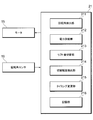
- FIG. 3 shows the control device 21 as such a functional control block diagram.
- the software module incorporated in the analog circuit or digital processor constituting the control device 21 does not necessarily have to be divided like the control block shown in FIG. That is, it may be configured to function as a plurality of control blocks, or may be further subdivided. As long as the control device 21 is configured to execute a processing flow described later, the actual configuration inside the control device 21 can be appropriately changed by those skilled in the art.
- control device 21 includes a rotation angle detection unit 211, a power supply unit 212, a lift amount switching unit 213, a switching frequency detection unit 214, and a timing change unit as functional control blocks. 215 and a storage unit 216.
- the rotation angle detection unit 211 processes the signal received from the rotation angle sensor 19.
- the rotation angle detector 211 detects the rotation angle of the cam 17 by this processing.
- the power supply unit 212 supplies driving power to the motor 15 of the actuator unit 13. Specifically, the power supply unit 212 supplies the electric power stored in a battery (not shown) to the motor 15 while adjusting the supply amount so that the rotation angle of the cam 17 matches the target value.
- the lift amount switching unit 213 switches the lift amounts of the intake valve and the exhaust valve of the internal combustion engine 100. As will be described later, the lift amount switching unit 213 switches the lift amount by displacing the control shaft 12.
- the switching frequency detection unit 214 detects the switching frequency of the lift amount by the lift amount switching unit 213. Specifically, the switching frequency detection unit 214 detects the frequency at which the switching frequency detection unit 214 switches the lift amounts of the intake valve and the exhaust valve of the internal combustion engine 100 during a predetermined period.
- the timing changing unit 215 changes the valve timing of the intake valve and the exhaust valve of the internal combustion engine 100. Specifically, the timing changing unit 215 changes the timing at which the intake valve and the exhaust valve of the internal combustion engine 100 are opened and closed.
- the storage unit 216 writes various data used for control processing in the control device 21 and enables reading of the data. Specifically, a map or the like to be described later is written in the storage unit 216 and can be read by the power supply unit 212 or the like.
- each block such as the rotation angle detection unit 211 of the control device 21 will be described as being performed by the control device 21 as a whole.
- control device 21 determines from the signal received from the rotation angle sensor 19 that there is a difference between the rotation angle of the cam 17 and the target value, the control device 21 supplies electric power to the motor 15 so that the rotation angle matches the target value. Start supplying.
- the motor 15 is rotationally driven according to the supplied electric energy, and the cam 17 is also rotated accordingly.
- the part with which the one end 12 a of the control shaft 12 abuts changes as the cam 17 rotates. Furthermore, the distance from the rotation center RC of the cam 17 to the one end 12a changes as the contact portion between the outer peripheral surface 17a and the one end 12a changes. Thereby, the control shaft 12 is displaced so as to reciprocate in the axial direction.
- the rotation angle of the cam 17 and the displacement of the control shaft 12 are uniquely related. For this reason, the position of the control shaft 12 can be converged to the target position by performing feedback control in which the detected value of the rotation angle of the cam 17 by the rotation angle sensor 19 matches the target value.
- first stationary part LP, the second stationary part MP, and the third stationary part HP of the outer peripheral surface 17a described above are formed so as not to displace the control shaft 12 when the cam 17 rotates. That is, the first stationary part LP, the second stationary part MP, and the third stationary part HP are all formed in an arc shape having a constant radius, and when the one end 12a of the control shaft 12 passes through them, it rotates. The distance from the center RC to the one end 12a is not changed. Therefore, only when the one end 12a is in contact with the first stationary part LP, the second stationary part MP, or the third stationary part HP, the control shaft 12 remains stationary without being displaced even when the cam 17 rotates. It becomes.
- the internal combustion engine 100 receives different actions depending on the position of the control shaft 12.
- the one end 12a of the control shaft 12 is in contact with the first stationary portion LP of the outer peripheral surface 17a of the cam 17, the lift amounts of the intake valve and the exhaust valve of the internal combustion engine 100 are VL.
- the one end 12a of the control shaft 12 is in contact with the third stationary portion HP of the outer peripheral surface 17a of the cam 17, the lift amounts of the intake valve and the exhaust valve of the internal combustion engine 100 become VH larger than VL. .
- the lift amounts of the intake valve and the exhaust valve of the internal combustion engine 100 are larger than VL and larger than VH. It becomes a small VM. That is, the control device 21 switches the lift amount of the intake valve and the exhaust valve to VL by switching the position where the control shaft 12 contacts to one of the first stationary part LP, the second stationary part MP, and the third stationary part HP. , VM, and VH.
- the control device 21 stores a first map as shown in FIG. 4 in the storage unit 216.
- the control device 21 switches the lift amounts of the intake valve and the exhaust valve of the internal combustion engine 100 based on the first map.
- the operating state of the internal combustion engine 100 is divided into three according to the combination of the load and the rotational speed.
- lift amounts VL, VM, and VH of the intake valve and the exhaust valve are assigned to the three operating states of the internal combustion engine 100, respectively.
- VL is assigned to the lift amounts of the intake valve and the exhaust valve.
- the operating state to which the lift amount VL is assigned changes to the operating state (first state) in which at least one of the load and the rotational speed of the internal combustion engine 100 is large
- the lift amount of the intake valve and the exhaust valve is set to VM. (First lift amount) is assigned.
- the lift amount of the intake valve and the exhaust valve is reduced to VH. Is assigned.
- VM is larger than VL and VH is larger than VM.
- the control device 21 determines the lift amount of the intake valve and the exhaust valve by switching the load and the rotational speed of the internal combustion engine 100 at that time against the first map, and performs switching. That is, the control device 21 determines which of the three sections of the first map the operating state of the internal combustion engine 100 at that time belongs to, and sets the lift amounts of the intake valve and the exhaust valve to the sections. Switch to the assigned lift amount.
- the control device 21 compares the load and the rotational speed of the internal combustion engine 100 with the first map at any time or periodically.
- the control device 21 does not change the lift amounts of the intake valve and the exhaust valve when there is no change in the section to which the operating state of the internal combustion engine 100 belongs before and after the comparison.
- the control device 21 displaces the control shaft 12 as described above when there is a change in the section to which the operating state of the internal combustion engine 100 belongs before and after the comparison. Then, the control device 21 switches the lift amount of the intake valve and the exhaust valve to any one of VL, VM, and VH assigned to the newly belonging section.
- the control device 21 rotates the motor 15 to displace the control shaft 12.
- the motor 15 has a maximum output as small as possible in order to reduce the size of the apparatus and reduce the manufacturing cost. For this reason, when the lift amounts VL, VM, and VH are switched, it is required to drive the motor 15 in the vicinity of the maximum duty.
- control processing of the control device 21 will be described with reference to FIGS.
- the control device 21 calculates the sum of the amount of power supplied to the motor 15 in a predetermined period T in S ⁇ b> 1.
- the control device 21 moves the third stationary portion HP while moving the one end 12a of the control shaft 12 from the first stationary portion LP to the second stationary portion MP and from the second stationary portion MP to the third stationary portion HP.
- electric power is supplied to the motor 15 in each of them.
- S1 the sum of the electric power supplied to the motor 15 in the predetermined period T is calculated.
- the sum of the amount of power supplied to the motor 15 in the predetermined period T can be calculated from the current and voltage supplied to the motor 15.
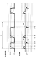
- the motor 15 is adjusted so that the detected value (solid line) of the rotation angle of the cam 17 by the rotation angle sensor 19 matches the target value (broken line) that changes between ⁇ L and ⁇ M.
- the value of the current supplied to the motor 15 shows a change as shown in the lower part of FIG.
- a period (from time t1 to time t2, from time t3 to time t4, from time t5 to time t6, from time t7 to time t8, from when the detection value by the rotation angle sensor 19 starts to change and coincides with the target value.
- the product of the areas S1, S2, S3, S4 shown in the lower part of FIG. 6 and the voltage supplied to the motor 15 is the amount of power supplied to the motor 15, and the sum of these is calculated in S1. To do.
- the control device 21 determines whether or not the calculated sum of power amounts is equal to or greater than a threshold value.
- the sum of the electric energy calculated in S1 has a proportional correlation with the switching frequency of the lift amounts VL, VM, and VH of the intake valve and the exhaust valve described above. The more frequently the lifts VL, VM, and VH are switched, the more frequently the motor 15 needs to be rotationally driven. Therefore, the sum of the amounts of power supplied to the motor 15 in the predetermined period T increases.
- control device 21 switches maps in S3.
- the map switching will be described in detail.
- the storage unit 216 of the control device 21 stores a second map shown in FIG. 7 in addition to the first map (see FIG. 4) described above.
- the operating state of the internal combustion engine 100 is classified using the load and the rotational speed of the internal combustion engine 100 as indices.
- the operation state of the internal combustion engine 100 is divided into three in the first map, whereas the operation state of the internal combustion engine 100 is divided into two in the second map. That is, in the first map, the operating state of the internal combustion engine 100 is divided into three that can be assigned lift amounts VL, VM, and VH, whereas in the second map, each of the lift amounts VL and VM is assigned. It is divided into two to be assigned.
- the control device 21 changes the control process so that the lift amounts VL and VM of the intake valve and the exhaust valve are switched using the second map instead of the first map used so far.
- the lift amount remains constant at the lift amount VM after switching to the second map. Will remain. That is, the switching frequency of the lift amount can be reduced.
- the control device 21 selects a valve timing correction amount in S4. That is, when the lift amount of the intake valve and the exhaust valve is VL, the correction amount of the valve timing is unchanged at 10 [deg ⁇ CA] regardless of which of the first map and the second map is used.
- the correction amount in the first map, in the operating state of the internal combustion engine 100 in which the lift amount of the intake valve and the exhaust valve is VM, the correction amount is 20 [deg ⁇ CA], whereas the correction amount when the second map is used.
- the correction amount is 30 [deg-CA].
- the correction amount is 30 [deg ⁇ CA]
- the correction amount is 50 [deg-CA].
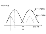
- the correction amount of the valve timing when using the first map is ⁇ 1 [deg ⁇ CA], whereas the valve timing when using the second map.
- the amount of timing correction is ⁇ 2 [deg ⁇ CA], which is larger than when the first map is used.
- the control device 21 when the frequency of switching the lift amount of the intake valve and the exhaust valve of the internal combustion engine 100 becomes a high frequency state in which the frequency is equal to or higher than the threshold value. , The switching is stopped. For this reason, when the switching of the lift amount becomes frequent, it is possible to stop the switching and to prevent the motor 15 from being further loaded. Therefore, overheating and failure of the motor 15 can be suppressed.
- the lift amount switching unit 213 of the control device 21 switches the lift amounts of the intake valve and the exhaust valve of the internal combustion engine 100 when the total amount of electric power supplied to the motor 15 exceeds the predetermined amount during the predetermined period T. Stop. That is, it is possible to easily estimate from the amount of power supplied to the motor 15 that the motor 15 is approaching the possibility of overheating or failure.
- control device 21 includes a timing changing unit 215 that changes the valve timing of the intake valve and the exhaust valve, and the timing changing unit 215 stops the switching of the lift amounts of the intake valve and the exhaust valve of the internal combustion engine 100. Change the valve timing. Thereby, it becomes possible to suppress the influence on drivability by switching the lift amount of the intake valve and the exhaust valve.
- control device 21 has a higher frequency state in which the frequency of switching the lift amount of the intake valve and the exhaust valve of the internal combustion engine 100 is equal to or higher than a threshold value, compared to a case where the frequency is not a high frequency state. Increase the amount of change when changing the valve timing. Thereby, it becomes possible to further suppress the influence on drivability by switching the lift amount of the intake valve and the exhaust valve.
Landscapes
- Engineering & Computer Science (AREA)
- Mechanical Engineering (AREA)
- General Engineering & Computer Science (AREA)
- Chemical & Material Sciences (AREA)
- Combustion & Propulsion (AREA)
- Output Control And Ontrol Of Special Type Engine (AREA)
- Valve Device For Special Equipments (AREA)
Abstract
モータ(15)を制御し、該モータの駆動によって内燃機関(100)の吸気バルブ及び排気バルブのリフト量(VL,VM,VH)を切り替える制御装置(21)は、モータに電力を供給する電力供給部(212)と、内燃機関の運転状態が所定条件となった場合にモータを駆動させ、吸気バルブ及び排気バルブのリフト量を第1リフト量(VM)とする第1状態と、吸気バルブ及び排気バルブのリフト量を第1リフト量よりも大きい第2リフト量(VH)とする第2状態と、を切り替えるリフト量切替部(213)と、第1状態と第2状態との切り替えの頻度を検出する切替頻度検出部(214)と、を備える。リフト量切替部は、第1状態と第2状態との切り替えの頻度が所定値以上となった状態である高頻度状態となった場合は、第1状態と第2状態との切り替えを停止する。
Description
本出願は、2014年12月3日に出願された日本特許出願2014-244892号に基づくもので、ここにその記載内容を援用する。
本開示は、モータを制御し、モータの駆動によって内燃機関の吸気バルブ及び排気バルブのリフト量を切り替える制御装置に関する。
車両に搭載される内燃機関において、吸気及び排気の特性を、内燃機関の運転状態に応じて切り替えるものが知られている。具体的には、内燃機関の気筒に設けられる吸気バルブや排気バルブのリフト量等を、その時々の内燃機関の運転状態に適したものとなるように切り替えを行う。
下記特許文献1には、モータ及びカムを用いて制御部材を変位させ、この制御部材の作用によって上記切替を行う制御装置が記載されている。モータの駆動に伴って回転するカムは、その外周面に制御部材を当接させるように構成されている。制御部材は、その一端においてカムの外周面に当接するとともに、他端が内燃機関まで延びている。
カムは、その回転中心から外周面までの距離が、外周面の部位によって異なるように形成されている。このため、制御部材とカムとの当接部位がカムの回転に伴って変化すると、制御部材が変位するように構成されている。
カムの外周面には、複数の静止部(段差部)が形成されている。この静止部では、カムの回転に伴う制御部材の変位量の傾きが、他の部位と異なるように形成されている。下記特許文献1の制御装置は、制御部材が、複数の静止部のいずれかと当接した状態とすることで、制御部材の位置を切替えるように構成されている。
制御部材は、位置を適宜切り替えられることにより、吸気バルブ及び排気バルブのリフト量を、その時々の内燃機関の運転状態に適したものに切り替える。これにより、内燃機関の出力向上や燃費削減等を図ることができる。
このような内燃機関では、装置の小型化や製造コストの抑制のため、上記リフト量の切り替えを行うモータは、可能な限り最大出力が小さいものを採用することが求められる。このため、上記リフト量の切り替えを行う際、モータをその最大デューティ近傍で駆動させることが求められる。
このような構成において、上記リフト量の切り替えが頻繁に発生すると、モータに過大な負荷がかかるおそれがある。これにより、モータが過熱し、故障するおそれがあった。
本開示の目的は、出力が小さいモータを制御して内燃機関の吸気バルブ及び排気バルブのリフト量の切り替えを行いながらも、モータの過熱や故障を抑制することが可能な制御装置を提供することにある。
本開示の一態様において、モータを制御し、モータの駆動によって内燃機関の吸気バルブ及び排気バルブのリフト量を切り替える制御装置は、モータに電力を供給する電力供給部と、内燃機関の運転状態が所定条件となった場合にモータを駆動させ、吸気バルブ及び排気バルブのリフト量を第1リフト量とする第1状態と、吸気バルブ及び排気バルブのリフト量を第1リフト量よりも大きい第2リフト量とする第2状態と、を切り替えるリフト量切替部と、第1状態と第2状態との切り替えの頻度を検出する切替頻度検出部と、を備える。リフト量切替部は、第1状態と第2状態との切り替えの頻度が所定値以上となった状態である高頻度状態となった場合は、第1状態と第2状態との切り替えを停止する。
本開示によれば、第1状態と第2状態との切り替えの頻度が所定値以上となった状態である高頻度状態となった場合は、第1状態と第2状態との切り替えを停止する。このため、第1状態と第2状態との切り替えが頻繁となった場合、当該切替を停止し、モータに更なる負荷がかかることを抑制することができる。したがって、モータの過熱や故障を抑制することが可能となる。
これによれば、出力が小さいモータを制御して内燃機関の吸気バルブ及び排気バルブのリフト量の切り替えを行いながらも、モータの過熱や故障を抑制することが可能な制御装置を提供する。
本開示についての上記およびその他の目的、特徴や利点は、添付の図面を参照しながら下記の詳細な記述により、より明確になる。
実施形態に係る制御装置を適用したバルブ制御システムの概略構成図である。
カム及び制御軸の概略構成を示す図である。
制御装置を説明するための制御ブロック図である。
内燃機関の運転状態とリフト量との関係を表した第1マップを示す図である。
制御装置による制御を示すフローチャートである。
カムの回転角とモータに供給された電流との関係を示す図である。
内燃機関の運転状態とリフト量との関係を表した第2マップを示す図である。
クランク角とバルブリフト量との関係を示す図である。
図面を参照しながら実施形態について説明する。説明の理解を容易にするため、各図面において同一の構成要素に対しては可能な限り同一の符号を付して、重複する説明は省略する。
まず、図1乃至図3を参照しながら、実施形態に係る制御装置21と、制御装置21が適用されるバルブ制御システム11と、の概要について説明する。バルブ制御システム11は、車両に搭載される内燃機関100の吸気バルブ及び排気バルブを制御するシステムである。バルブ制御システム11は、制御軸12と、アクチュエータ部13と、バルブ開閉特性変更機構14と、を有している。
図1に示されるように、制御軸12は、その軸方向にスライドすることで変位する棒状の部材である。制御軸12の一端12aはアクチュエータ部13側に設けられ、他端12bはバルブ開閉特性変更機構14側に設けられている。
アクチュエータ部13は、制御軸12に軸方向の力を付加して、制御軸12を変位させる機構である。アクチュエータ部13は、モータ15と、減速機16と、カム17と、回転角センサ19と、を有している。
モータ15は、電力の供給を受けることで回転駆動し、トルクを発生させる原動機である。モータ15の出力軸は減速機16に接続されている。モータ15が発生させたトルクは、減速機16を介してカム17に伝達される。
図2に示されるように、カム17は、モータ15の回転に伴って減速機16からトルクが伝達されることで、回転中心RC周りに回転するように構成されている。また、カム17の外周面17aは曲面として形成されている。また、カム17は、その回転中心RCから外周面17aまでの距離が、外周面17aの部位によって互いに異なるように形成されている。
カム17の外周面17aには、第1静止部LP、第2静止部MP及び第3静止部HPが、互いに間隔を空けて形成されている。このうち、第1静止部LPは、回転中心RCからの距離が最も小さい部位である。また、第3静止部HPは、回転中心RCからの距離が最も大きい部位である。すなわち、回転中心RCからの距離は、第1静止部LPから第2静止部MPを経て第3静止部HPまで、3段階で大きくなるように構成されている。尚、図2では、説明の便宜上、第1静止部LP、第2静止部MP及び第3静止部HPを太線で示している。このようなカム17の外周面17aには、制御軸12の一端12aが当接している。
回転角センサ19は、カム17の近傍に配置され、カム17の基準位置からの回転角に応じて信号を出力するセンサである。回転角センサ19が出力する信号は、信号線を介して制御装置21(図1参照)に入力される。
バルブ開閉特性変更機構14は、内燃機関100に取り付けられる。バルブ開閉特性変更機構14は、吸気バルブ及び排気バルブの開閉特性を変更することで、内燃機関100の吸気及び排気の特性を切り替える機構である。具体的には、バルブ開閉特性変更機構14は、内燃機関100の吸気バルブ及び排気バルブの最大リフト量と作用角を変化させる。バルブ開閉特性変更機構14には、制御軸12の他端12bが接続される。
制御装置21は、以上のようなバルブ制御システム11を制御する。制御装置21は、モータ15及び回転角センサ19と電気的に接続されており、信号を受信して処理を行ったり、電力の供給を行ったりする。
制御装置21は、その一部又は全部が、アナログ回路で構成されるか、メモリを備えたデジタルプロセッサとして構成される。いずれにしても、受信した信号に基づいて制御信号を出力する機能を果たすため、制御装置21には機能的な制御ブロックが構成される。図3は、制御装置21を、このような機能的な制御ブロック図として示したものである。尚、制御装置21を構成するアナログ回路又はデジタルプロセッサに組み込まれるソフトウェアのモジュールは、必ずしも図3に示す制御ブロックのように分割されている必要はない。すなわち、複数の制御ブロックの働きをするものとして構成されていても構わず、更に細分化されていても構わない。制御装置21として後述する処理フローを実行できるように構成されていれば、制御装置21内部の実際の構成は当業者が適宜変更できる。
図3に示されるように、制御装置21は、機能的な制御ブロックとして、回転角検出部211と、電力供給部212と、リフト量切替部213と、切替頻度検出部214と、タイミング変更部215と、記憶部216と、を備えている。
回転角検出部211は、回転角センサ19から受信した信号を処理する。回転角検出部211は、当該処理によってカム17の回転角を検出する。
電力供給部212は、アクチュエータ部13のモータ15に駆動用の電力を供給する。詳細には、電力供給部212は、図示しないバッテリに蓄えられている電力を、カム17の回転角が目標値と一致するように、供給量を調整しながらモータ15に供給する。
リフト量切替部213は、内燃機関100の吸気バルブ及び排気バルブのリフト量の切り替えを行う。後述するように、リフト量切替部213は、制御軸12を変位させることで当該リフト量の切り替えを行う。
切替頻度検出部214は、リフト量切替部213によるリフト量の切替頻度を検出する。詳細には、切替頻度検出部214は、所定期間において切替頻度検出部214が内燃機関100の吸気バルブ及び排気バルブのリフト量の切り替えを行った頻度を検出する。
タイミング変更部215は、内燃機関100の吸気バルブ及び排気バルブのバルブタイミングを変更する。具体的には、タイミング変更部215は、内燃機関100の吸気バルブ及び排気バルブが開閉するタイミングを変更する。
記憶部216は、制御装置21における制御処理に使用される種々のデータを書き込むとともに、当該データの読み出しを可能とする。具体的には、記憶部216には、後述するマップ等が書き込まれるとともに、それらは電力供給部212等によって読み出すことができる。
尚、以下では簡便のため、制御装置21の回転角検出部211等の各ブロックによって行われている処理も、総括して制御装置21が行うものとして説明する。
制御装置21は、回転角センサ19から受信した信号により、カム17の回転角と目標値とに乖離があると判断した場合に、当該回転角を目標値に一致させるべく、モータ15に電力の供給を開始する。モータ15は、供給された電力量に応じて回転駆動し、それに伴ってカム17も回転する。
カム17の外周面17aのうち、制御軸12の一端12aが当接する部位は、カム17の回転に伴って変化する。さらに、外周面17aと一端12aとの当接部位が変化することにより、カム17の回転中心RCから一端12aまでの距離が変化する。これにより、制御軸12が軸方向に往復するように変位する。
ここで、カム17の回転角と制御軸12の変位は一義的な関係にある。このため、回転角センサ19によるカム17の回転角の検出値を、目標値に一致させるフィードバック制御を行うことで、制御軸12の位置も目標位置に収束させることができる。
また、前述した外周面17aの第1静止部LP、第2静止部MP及び第3静止部HPは、カム17の回転時に制御軸12を変位させないように形成されている。つまり、第1静止部LP、第2静止部MP及び第3静止部HPは、いずれも半径が一定の円弧状に形成されており、制御軸12の一端12aがそれらを通過する際は、回転中心RCから一端12aまでの距離が変化しないように構成されている。このため、一端12aが第1静止部LP、第2静止部MP又は第3静止部HPと当接している場合のみ、カム17が回転しても制御軸12は変位することなく、静止した状態となる。
内燃機関100は、制御軸12の位置に応じて異なる作用を受ける。制御軸12の一端12aがカム17の外周面17aの第1静止部LPと当接している場合、内燃機関100の吸気バルブ及び排気バルブのリフト量はVLとなる。一方、制御軸12の一端12aがカム17の外周面17aの第3静止部HPと当接している場合は、内燃機関100の吸気バルブ及び排気バルブのリフト量は、VLよりも大きいVHとなる。また、制御軸12の一端12aがカム17の外周面17aの第2静止部MPと当接している場合は、内燃機関100の吸気バルブ及び排気バルブのリフト量は、VLよりも大きくVHよりも小さいVMとなる。すなわち、制御装置21は、制御軸12が当接する位置を第1静止部LP、第2静止部MP及び第3静止部HPのいずれかに切り替えることにより、吸気バルブ及び排気バルブのリフト量をVL,VM,VHの3段階に切り替えることができる。
次に、図4を参照しながら、以上のように構成されたバルブ制御システム11における内燃機関100の吸気バルブ及び排気バルブのリフト量VL,VM,VHの切り替えについて説明する。
制御装置21は、その記憶部216に、図4に示されるような第1マップを記憶している。制御装置21は、この第1マップに基づいて、内燃機関100の吸気バルブ及び排気バルブのリフト量の切り替えを行う。
この第1マップでは、負荷と回転数との組み合わせによって内燃機関100の運転状態を3つに区分している。第1マップは、この内燃機関100の3つの運転状態のそれぞれに、吸気バルブ及び排気バルブのリフト量VL,VM,VHを割り当てたものとなっている。
具体的には、第1マップでは、内燃機関100が低負荷、低回転数の運転状態にある場合では、吸気バルブ及び排気バルブのリフト量にVLが割り当てられている。また、リフト量VLが割り当てられている運転状態から、内燃機関100の負荷及び回転数の少なくとも一方が大きい運転状態(第1状態)となった場合では、吸気バルブ及び排気バルブのリフト量にVM(第1リフト量)が割り当てられている。さらに、リフト量VMが割り当てられている運転状態から、内燃機関100の負荷及び回転数の少なくとも一方が大きい運転状態(第2状態)となった場合では、吸気バルブ及び排気バルブのリフト量にVHが割り当てられている。前述したように、VMはVLよりも大きく、VHはVMよりも大きい。
制御装置21は、その時々の内燃機関100の負荷及び回転数を第1マップに対照させることで、吸気バルブ及び排気バルブのリフト量を決定し、切替を行う。すなわち、制御装置21は、その際の内燃機関100の運転状態が、前述した第1マップの3つの区分のいずれに属するかを判断するとともに、吸気バルブ及び排気バルブのリフト量を、その区分に割り当てられたリフト量に切り替えるものである。
制御装置21は、随時又は定期的に内燃機関100の負荷及び回転数を、第1マップに対照させる。制御装置21は、対照の前後で、内燃機関100の運転状態が属する区分に変化が無い場合は、吸気バルブ及び排気バルブのリフト量は変更しない。制御装置21は、対照の前後で、内燃機関100の運転状態が属する区分に変化があった場合は、前述したように制御軸12を変位させる。そして、制御装置21は、吸気バルブ及び排気バルブのリフト量を、新たに属する区分に割り当てられたVL,VM,VHのいずれかに切り替える。
ところで、吸気バルブ及び排気バルブのリフト量VL,VM,VHの切り替えの際、制御装置21は、モータ15を回転駆動させて制御軸12を変位させる。このモータ15は、装置の小型化や製造コストの抑制のため、可能な限り最大出力が小さいものを採用したいという要求がある。このため、リフト量VL,VM,VHの切り替えを行う際、モータ15をその最大デューティ近傍で駆動させることが求められる。
このような構成において、リフト量VL,VM,VHの切り替えが頻繁に発生すると、モータ15に過大な負荷がかかるおそれがある。このため、モータ15が過熱し、故障する事態を招くおそれがある。
そこで、本実施形態に係る制御装置21では、モータ15が過熱するおそれがある状況では、制御処理に変更を行ってこの課題の解決を図っている。以下、図5乃至図8を参照しながら、制御装置21の制御処理について説明する。
まず、図5に示されるように、制御装置21は、S1で、所定期間Tにおいて、モータ15に供給された電力量の和を算出する。制御装置21は、制御軸12の一端12aを、第1静止部LPから第2静止部MPまで移動させる間、第2静止部MPから第3静止部HPまで移動させる間、第3静止部HPから第1静止部LPまで移動させる間、のそれぞれにおいてモータ15に電力を供給する。S1では、所定期間Tにおいてこのようにモータ15に供給された電力量の和を算出する。
ここで、所定期間Tにおいてモータ15に供給された電力量の和は、モータ15に供給された電流及び電圧から算出することができる。図6の上段に示されるように、回転角センサ19によるカム17の回転角の検出値(実線)を、θLとθMとの間で変化する目標値(破線)に一致させるようにモータ15を駆動させる間に、モータ15に供給される電流の値は図6の下段に示されるような変化を示す。このうち、回転角センサ19による検出値が変化を開始してから、目標値と一致するまで期間(時刻t1から時刻t2、時刻t3から時刻t4、時刻t5から時刻t6、時刻t7から時刻t8の各期間)において、図6の下段に示す面積S1,S2,S3,S4と、モータ15に供給された電圧との積がモータ15に供給された電力量であり、S1ではこれらの和を算出する。
次に、制御装置21は、図5に示されるS2で、算出した電力量の和が閾値以上であるか否かを判定する。S1で算出された電力量の和は、前述した吸気バルブ及び排気バルブのリフト量VL,VM,VHの切り替えの頻度と比例的な相関がある。リフト量VL,VM,VHの切り替えが頻繁に行われるほど、モータ15を頻繁に回転駆動させる必要があるため、所定期間Tにおいてモータ15に供給された電力量の和が大きくなる。
したがって、図5に示されるS2で、算出した電力量の和が閾値以上と判定された場合(S2:Yes)、モータ15は高頻度で回転駆動しており、過熱のおそれがあると推定することができる。この場合、制御装置21は、次にS3に進む。
次に、制御装置21は、S3で、マップの切り替えを行う。このマップの切り替えについて詳述すると、まず、制御装置21の記憶部216には、前述した第1マップ(図4参照)の他にも、図7に示される第2マップが記憶されている。
この第2マップでは、第1マップ同様に、内燃機関100の負荷及び回転数を指標として、内燃機関100の運転状態を区分している。ただし、第1マップでは、内燃機関100の運転状態が3つに区分されていたのに対し、第2マップでは、内燃機関100の運転状態が2つに区分されている点で異なる。すなわち、第1マップでは、内燃機関100の運転状態はリフト量VL,VM,VHのそれぞれを割り当てられる3つに区分されていたのに対し、第2マップでは、リフト量VL,VMのそれぞれを割り当てられる2つに区分されている。
制御装置21は、S3で、それまで用いていた第1マップに代えて、第2マップを用いて吸気バルブ及び排気バルブのリフト量VL,VMの切り替えを行うよう制御処理の変更を行う。これにより、第1マップを用いていた際は、リフト量VM,VHで切り替えを行っていた内燃機関100の運転状態でも、第2マップに切り替えた後は、リフト量はリフト量VMで一定のままとなる。すなわち、リフト量の切替頻度の低減が図られる。
次に、制御装置21は、S4で、バルブタイミングの補正量の選択を行う。すなわち、吸気バルブ及び排気バルブのリフト量をVLとする場合は、第1マップ及び第2マップのいずれを用いる場合でも、バルブタイミングの補正量は10[deg-CA]で不変とする。しかし、第1マップにおいて、吸気バルブ及び排気バルブのリフト量をVMとする内燃機関100の運転状態では、補正量は20[deg-CA]であるのに対し、第2マップを用いた場合の補正量は30[deg-CA]とする。また、第1マップにおいて、吸気バルブ及び排気バルブのリフト量をVHとする内燃機関100の運転状態では、補正量は30[deg-CA]であるのに対し、第2マップを用いた場合の補正量は50[deg-CA]とする。
これにより、図8に示されるように、第1マップを使用している際のバルブタイミングの補正量はθ1[deg-CA]であるのに対し、第2マップを使用している際のバルブタイミングの補正量はθ2[deg-CA]と、第1マップを使用している際よりも大きくなる。
以上のように、本実施形態に係る制御装置21では、内燃機関100の吸気バルブ及び排気バルブのリフト量の切り替えを行った頻度が閾値以上となった状態である高頻度状態となった場合は、当該切替を停止する。このため、リフト量の切り替えが頻繁となった場合、当該切替を停止し、モータ15に更なる負荷がかかることを抑制することができる。したがって、モータ15の過熱や故障を抑制することが可能となる。
また、制御装置21のリフト量切替部213は、所定期間Tにモータ15に供給した電力量の総和が所定量を超えた場合に、内燃機関100の吸気バルブ及び排気バルブのリフト量の切り替えを停止する。すなわち、モータ15に過熱や故障の可能性が迫っていることを、モータ15に供給した電力量から容易に推定することが可能となる。
また、制御装置21は、吸気バルブ及び排気バルブのバルブタイミングを変更するタイミング変更部215を備え、タイミング変更部215は、内燃機関100の吸気バルブ及び排気バルブのリフト量の切り替えを停止した場合に、バルブタイミングを変更する。これにより、吸気バルブ及び排気バルブのリフト量の切り替えを行うことによるドライバビリティへの影響を抑制することが可能となる。
また、制御装置21は、内燃機関100の吸気バルブ及び排気バルブのリフト量の切り替えを行った頻度が閾値以上となった状態である高頻度状態となった場合は、高頻度状態でない場合に比べて、バルブタイミングを変更する際の変更量を大きくする。これにより、吸気バルブ及び排気バルブのリフト量の切り替えを行うことによるドライバビリティへの影響を更に抑制することが可能となる。
以上、具体例を参照しつつ実施形態について説明した。しかし、本開示はこれらの具体例に限定されるものではない。すなわち、これら具体例に、当業者が適宜設計変更を加えたものも、本開示の範囲に包含される。前述した各具体例が備える各要素およびその配置、材料、条件、形状、サイズなどは、例示したものに限定されるわけではなく適宜変更することができる。
Claims (4)
- モータ(15)を制御し、該モータの駆動によって内燃機関(100)の吸気バルブ及び排気バルブのリフト量(VL,VM,VH)を切り替える制御装置(21)であって、
前記モータに電力を供給する電力供給部(212)と、
前記内燃機関の運転状態が所定条件となった場合に前記モータを駆動させ、前記吸気バルブ及び前記排気バルブのリフト量を第1リフト量(VM)とする第1状態と、前記吸気バルブ及び前記排気バルブのリフト量を前記第1リフト量よりも大きい第2リフト量(VH)とする第2状態と、を切り替えるリフト量切替部(213)と、
前記第1状態と前記第2状態との切り替えの頻度を検出する切替頻度検出部(214)と、を備え、
前記リフト量切替部は、前記第1状態と前記第2状態との切り替えの頻度が所定値以上となった状態である高頻度状態となった場合は、前記第1状態と前記第2状態との切り替えを停止する制御装置。 - 前記リフト量切替部は、所定期間(T)に前記モータに供給した電力量の総和が所定量を超えた場合に、前記第1状態と前記第2状態との切り替えを停止する請求項1に記載の制御装置。
- 前記吸気バルブ及び前記排気バルブのバルブタイミングを変更するタイミング変更部(215)をさらに備え、
前記タイミング変更部は、前記第1状態と前記第2状態との切り替えを停止した場合に、前記バルブタイミングを変更する請求項2に記載の制御装置。 - 前記高頻度状態となった場合は、前記高頻度状態でない場合に比べて、前記バルブタイミングを変更する際の変更量を大きくする請求項3に記載の制御装置。
Priority Applications (1)
| Application Number | Priority Date | Filing Date | Title |
|---|---|---|---|
| DE112015005468.5T DE112015005468T5 (de) | 2014-12-03 | 2015-11-24 | Steuervorrichtung |
Applications Claiming Priority (2)
| Application Number | Priority Date | Filing Date | Title |
|---|---|---|---|
| JP2014244892A JP2016108977A (ja) | 2014-12-03 | 2014-12-03 | 制御装置 |
| JP2014-244892 | 2014-12-03 |
Publications (1)
| Publication Number | Publication Date |
|---|---|
| WO2016088331A1 true WO2016088331A1 (ja) | 2016-06-09 |
Family
ID=56091296
Family Applications (1)
| Application Number | Title | Priority Date | Filing Date |
|---|---|---|---|
| PCT/JP2015/005828 Ceased WO2016088331A1 (ja) | 2014-12-03 | 2015-11-24 | 制御装置 |
Country Status (3)
| Country | Link |
|---|---|
| JP (1) | JP2016108977A (ja) |
| DE (1) | DE112015005468T5 (ja) |
| WO (1) | WO2016088331A1 (ja) |
Citations (4)
| Publication number | Priority date | Publication date | Assignee | Title |
|---|---|---|---|---|
| JP2004183591A (ja) * | 2002-12-05 | 2004-07-02 | Toyota Motor Corp | 可変動弁機構を有する内燃機関の制御装置 |
| JP2005220759A (ja) * | 2004-02-03 | 2005-08-18 | Hitachi Ltd | 内燃機関のリフト量可変制御装置 |
| JP2009115036A (ja) * | 2007-11-08 | 2009-05-28 | Toyota Motor Corp | 可変動弁機構の制御装置 |
| JP2014156793A (ja) * | 2013-02-14 | 2014-08-28 | Toyota Motor Corp | 可変動弁機構の制御装置 |
-
2014
- 2014-12-03 JP JP2014244892A patent/JP2016108977A/ja active Pending
-
2015
- 2015-11-24 DE DE112015005468.5T patent/DE112015005468T5/de not_active Withdrawn
- 2015-11-24 WO PCT/JP2015/005828 patent/WO2016088331A1/ja not_active Ceased
Patent Citations (4)
| Publication number | Priority date | Publication date | Assignee | Title |
|---|---|---|---|---|
| JP2004183591A (ja) * | 2002-12-05 | 2004-07-02 | Toyota Motor Corp | 可変動弁機構を有する内燃機関の制御装置 |
| JP2005220759A (ja) * | 2004-02-03 | 2005-08-18 | Hitachi Ltd | 内燃機関のリフト量可変制御装置 |
| JP2009115036A (ja) * | 2007-11-08 | 2009-05-28 | Toyota Motor Corp | 可変動弁機構の制御装置 |
| JP2014156793A (ja) * | 2013-02-14 | 2014-08-28 | Toyota Motor Corp | 可変動弁機構の制御装置 |
Also Published As
| Publication number | Publication date |
|---|---|
| DE112015005468T5 (de) | 2017-08-17 |
| JP2016108977A (ja) | 2016-06-20 |
Similar Documents
| Publication | Publication Date | Title |
|---|---|---|
| CN105683629B (zh) | 作业车辆和作业车辆的控制方法 | |
| JP7226092B2 (ja) | シフトレンジ制御装置 | |
| CN107429616A (zh) | 车辆用驱动机构的控制装置以及控制方法 | |
| KR101459456B1 (ko) | 가변 밸브 리프트 장치가 구비된 엔진의 오일 펌프 제어 방법 및 시스템 | |
| JP4022552B2 (ja) | ブラシレスモータの駆動方法とその駆動制御装置 | |
| JP5012963B2 (ja) | アクチュエータの制御装置 | |
| JP2020200878A (ja) | シフトレンジ制御装置 | |
| JP7745354B2 (ja) | 車両制御装置 | |
| CN107524489A (zh) | 用于控制连续可变阀门持续时间的系统及其操作方法 | |
| WO2016088331A1 (ja) | 制御装置 | |
| JP4888160B2 (ja) | 内燃機関の可変動弁装置 | |
| JP6304003B2 (ja) | 制御装置 | |
| JP2018048721A (ja) | 制御装置および制御方法 | |
| JP6304009B2 (ja) | 制御装置 | |
| JP7169218B2 (ja) | アクチュエータ制御装置 | |
| CN114483331A (zh) | 可变气门升程系统的控制方法 | |
| JP4424372B2 (ja) | アクチュエータの制御装置 | |
| JP4061976B2 (ja) | バルブリフト量調整装置 | |
| JP4826505B2 (ja) | 可変動弁機構の制御装置 | |
| KR20170067523A (ko) | 하이브리드 차량의 제어 장치 및 방법 | |
| KR101593925B1 (ko) | 가변 밸브 타이밍 제어 방법 | |
| JP4798234B2 (ja) | 可変動弁システム | |
| JP5272495B2 (ja) | 電動モータの制御装置 | |
| JP5423421B2 (ja) | 吸排気弁制御装置 | |
| JP7247900B2 (ja) | 電動可変動弁機構の制御装置 |
Legal Events
| Date | Code | Title | Description |
|---|---|---|---|
| 121 | Ep: the epo has been informed by wipo that ep was designated in this application |
Ref document number: 15865225 Country of ref document: EP Kind code of ref document: A1 |
|
| WWE | Wipo information: entry into national phase |
Ref document number: 112015005468 Country of ref document: DE |
|
| 122 | Ep: pct application non-entry in european phase |
Ref document number: 15865225 Country of ref document: EP Kind code of ref document: A1 |