WO2016084861A1 - 接合装置と接合方法 - Google Patents
接合装置と接合方法 Download PDFInfo
- Publication number
- WO2016084861A1 WO2016084861A1 PCT/JP2015/083112 JP2015083112W WO2016084861A1 WO 2016084861 A1 WO2016084861 A1 WO 2016084861A1 JP 2015083112 W JP2015083112 W JP 2015083112W WO 2016084861 A1 WO2016084861 A1 WO 2016084861A1
- Authority
- WO
- WIPO (PCT)
- Prior art keywords
- patch
- bonding
- pressing
- corner
- pressing member
- Prior art date
Links
- 238000000034 method Methods 0.000 title claims description 40
- 238000003825 pressing Methods 0.000 claims abstract description 174
- 239000000463 material Substances 0.000 claims abstract description 81
- 239000012783 reinforcing fiber Substances 0.000 claims abstract description 54
- 238000010438 heat treatment Methods 0.000 claims description 35
- 238000005304 joining Methods 0.000 claims description 24
- 230000004044 response Effects 0.000 claims description 6
- 238000003466 welding Methods 0.000 claims 7
- 230000037303 wrinkles Effects 0.000 abstract description 30
- 239000000565 sealant Substances 0.000 abstract description 13
- 230000006837 decompression Effects 0.000 abstract description 9
- 238000013461 design Methods 0.000 abstract description 8
- 229920005989 resin Polymers 0.000 description 26
- 239000011347 resin Substances 0.000 description 26
- 239000011159 matrix material Substances 0.000 description 15
- 238000000465 moulding Methods 0.000 description 14
- 239000002131 composite material Substances 0.000 description 12
- 230000008569 process Effects 0.000 description 10
- 230000008439 repair process Effects 0.000 description 9
- 239000000835 fiber Substances 0.000 description 8
- 229920001187 thermosetting polymer Polymers 0.000 description 6
- 238000007872 degassing Methods 0.000 description 5
- -1 polyparaphenylene benzobisoxazole Polymers 0.000 description 5
- 238000005520 cutting process Methods 0.000 description 4
- 238000002474 experimental method Methods 0.000 description 4
- 229920005992 thermoplastic resin Polymers 0.000 description 4
- 238000001816 cooling Methods 0.000 description 3
- 230000009977 dual effect Effects 0.000 description 3
- 229920001971 elastomer Polymers 0.000 description 3
- 239000006260 foam Substances 0.000 description 3
- 230000005484 gravity Effects 0.000 description 3
- ISWSIDIOOBJBQZ-UHFFFAOYSA-N Phenol Chemical compound OC1=CC=CC=C1 ISWSIDIOOBJBQZ-UHFFFAOYSA-N 0.000 description 2
- 239000004696 Poly ether ether ketone Substances 0.000 description 2
- 239000004697 Polyetherimide Substances 0.000 description 2
- 239000004734 Polyphenylene sulfide Substances 0.000 description 2
- 239000000853 adhesive Substances 0.000 description 2
- 230000001070 adhesive effect Effects 0.000 description 2
- XAGFODPZIPBFFR-UHFFFAOYSA-N aluminium Chemical compound [Al] XAGFODPZIPBFFR-UHFFFAOYSA-N 0.000 description 2
- 238000005452 bending Methods 0.000 description 2
- 230000015572 biosynthetic process Effects 0.000 description 2
- 230000006872 improvement Effects 0.000 description 2
- 238000004519 manufacturing process Methods 0.000 description 2
- 229920001643 poly(ether ketone) Polymers 0.000 description 2
- 229920001652 poly(etherketoneketone) Polymers 0.000 description 2
- 229920002857 polybutadiene Polymers 0.000 description 2
- 229920002530 polyetherether ketone Polymers 0.000 description 2
- 229920001601 polyetherimide Polymers 0.000 description 2
- 229920000069 polyphenylene sulfide Polymers 0.000 description 2
- 238000002360 preparation method Methods 0.000 description 2
- 238000012545 processing Methods 0.000 description 2
- 230000001737 promoting effect Effects 0.000 description 2
- 230000009467 reduction Effects 0.000 description 2
- 239000005060 rubber Substances 0.000 description 2
- 238000007493 shaping process Methods 0.000 description 2
- 229920002379 silicone rubber Polymers 0.000 description 2
- 239000004945 silicone rubber Substances 0.000 description 2
- 244000257022 tick clover Species 0.000 description 2
- 238000001721 transfer moulding Methods 0.000 description 2
- 230000004580 weight loss Effects 0.000 description 2
- XQUPVDVFXZDTLT-UHFFFAOYSA-N 1-[4-[[4-(2,5-dioxopyrrol-1-yl)phenyl]methyl]phenyl]pyrrole-2,5-dione Chemical compound O=C1C=CC(=O)N1C(C=C1)=CC=C1CC1=CC=C(N2C(C=CC2=O)=O)C=C1 XQUPVDVFXZDTLT-UHFFFAOYSA-N 0.000 description 1
- CMLFRMDBDNHMRA-UHFFFAOYSA-N 2h-1,2-benzoxazine Chemical compound C1=CC=C2C=CNOC2=C1 CMLFRMDBDNHMRA-UHFFFAOYSA-N 0.000 description 1
- 229920000049 Carbon (fiber) Polymers 0.000 description 1
- RYGMFSIKBFXOCR-UHFFFAOYSA-N Copper Chemical compound [Cu] RYGMFSIKBFXOCR-UHFFFAOYSA-N 0.000 description 1
- 239000004593 Epoxy Substances 0.000 description 1
- VGGSQFUCUMXWEO-UHFFFAOYSA-N Ethene Chemical compound C=C VGGSQFUCUMXWEO-UHFFFAOYSA-N 0.000 description 1
- 239000005977 Ethylene Substances 0.000 description 1
- 244000043261 Hevea brasiliensis Species 0.000 description 1
- 229920000459 Nitrile rubber Polymers 0.000 description 1
- 239000004677 Nylon Substances 0.000 description 1
- 239000004952 Polyamide Substances 0.000 description 1
- 239000005062 Polybutadiene Substances 0.000 description 1
- 239000004698 Polyethylene Substances 0.000 description 1
- 239000004642 Polyimide Substances 0.000 description 1
- 239000004372 Polyvinyl alcohol Substances 0.000 description 1
- 229920006311 Urethane elastomer Polymers 0.000 description 1
- NIXOWILDQLNWCW-UHFFFAOYSA-N acrylic acid group Chemical group C(C=C)(=O)O NIXOWILDQLNWCW-UHFFFAOYSA-N 0.000 description 1
- 238000013459 approach Methods 0.000 description 1
- 229920006231 aramid fiber Polymers 0.000 description 1
- 238000011074 autoclave method Methods 0.000 description 1
- 229920005549 butyl rubber Polymers 0.000 description 1
- 239000004917 carbon fiber Substances 0.000 description 1
- 239000003054 catalyst Substances 0.000 description 1
- 239000000919 ceramic Substances 0.000 description 1
- 230000008859 change Effects 0.000 description 1
- 239000003795 chemical substances by application Substances 0.000 description 1
- 230000006835 compression Effects 0.000 description 1
- 238000007906 compression Methods 0.000 description 1
- 239000004643 cyanate ester Substances 0.000 description 1
- 230000007423 decrease Effects 0.000 description 1
- 239000013013 elastic material Substances 0.000 description 1
- 239000000806 elastomer Substances 0.000 description 1
- 238000005516 engineering process Methods 0.000 description 1
- 239000003365 glass fiber Substances 0.000 description 1
- 239000002184 metal Substances 0.000 description 1
- 229910052751 metal Inorganic materials 0.000 description 1
- VNWKTOKETHGBQD-UHFFFAOYSA-N methane Chemical compound C VNWKTOKETHGBQD-UHFFFAOYSA-N 0.000 description 1
- 238000012986 modification Methods 0.000 description 1
- 230000004048 modification Effects 0.000 description 1
- 229920003052 natural elastomer Polymers 0.000 description 1
- 229920001194 natural rubber Polymers 0.000 description 1
- 229920001778 nylon Polymers 0.000 description 1
- 230000000704 physical effect Effects 0.000 description 1
- 229920003192 poly(bis maleimide) Polymers 0.000 description 1
- 229920001084 poly(chloroprene) Polymers 0.000 description 1
- 229920002647 polyamide Polymers 0.000 description 1
- 229920000573 polyethylene Polymers 0.000 description 1
- 229920001721 polyimide Polymers 0.000 description 1
- 229920013657 polymer matrix composite Polymers 0.000 description 1
- 239000011160 polymer matrix composite Substances 0.000 description 1
- 239000003505 polymerization initiator Substances 0.000 description 1
- 229920002451 polyvinyl alcohol Polymers 0.000 description 1
- 239000000843 powder Substances 0.000 description 1
- QQONPFPTGQHPMA-UHFFFAOYSA-N propylene Natural products CC=C QQONPFPTGQHPMA-UHFFFAOYSA-N 0.000 description 1
- 125000004805 propylene group Chemical group [H]C([H])([H])C([H])([*:1])C([H])([H])[*:2] 0.000 description 1
- 239000000523 sample Substances 0.000 description 1
- 125000006850 spacer group Chemical group 0.000 description 1
- 229920003048 styrene butadiene rubber Polymers 0.000 description 1
- 125000003944 tolyl group Chemical group 0.000 description 1
- 229920006305 unsaturated polyester Polymers 0.000 description 1
- 229920001567 vinyl ester resin Polymers 0.000 description 1
Images


Classifications
-
- B—PERFORMING OPERATIONS; TRANSPORTING
- B29—WORKING OF PLASTICS; WORKING OF SUBSTANCES IN A PLASTIC STATE IN GENERAL
- B29C—SHAPING OR JOINING OF PLASTICS; SHAPING OF MATERIAL IN A PLASTIC STATE, NOT OTHERWISE PROVIDED FOR; AFTER-TREATMENT OF THE SHAPED PRODUCTS, e.g. REPAIRING
- B29C43/00—Compression moulding, i.e. applying external pressure to flow the moulding material; Apparatus therefor
- B29C43/02—Compression moulding, i.e. applying external pressure to flow the moulding material; Apparatus therefor of articles of definite length, i.e. discrete articles
- B29C43/10—Isostatic pressing, i.e. using non-rigid pressure-exerting members against rigid parts or dies
- B29C43/12—Isostatic pressing, i.e. using non-rigid pressure-exerting members against rigid parts or dies using bags surrounding the moulding material or using membranes contacting the moulding material
-
- B—PERFORMING OPERATIONS; TRANSPORTING
- B29—WORKING OF PLASTICS; WORKING OF SUBSTANCES IN A PLASTIC STATE IN GENERAL
- B29C—SHAPING OR JOINING OF PLASTICS; SHAPING OF MATERIAL IN A PLASTIC STATE, NOT OTHERWISE PROVIDED FOR; AFTER-TREATMENT OF THE SHAPED PRODUCTS, e.g. REPAIRING
- B29C43/00—Compression moulding, i.e. applying external pressure to flow the moulding material; Apparatus therefor
- B29C43/32—Component parts, details or accessories; Auxiliary operations
- B29C43/36—Moulds for making articles of definite length, i.e. discrete articles
- B29C43/3642—Bags, bleeder sheets or cauls for isostatic pressing
-
- B—PERFORMING OPERATIONS; TRANSPORTING
- B29—WORKING OF PLASTICS; WORKING OF SUBSTANCES IN A PLASTIC STATE IN GENERAL
- B29C—SHAPING OR JOINING OF PLASTICS; SHAPING OF MATERIAL IN A PLASTIC STATE, NOT OTHERWISE PROVIDED FOR; AFTER-TREATMENT OF THE SHAPED PRODUCTS, e.g. REPAIRING
- B29C65/00—Joining or sealing of preformed parts, e.g. welding of plastics materials; Apparatus therefor
- B29C65/02—Joining or sealing of preformed parts, e.g. welding of plastics materials; Apparatus therefor by heating, with or without pressure
-
- B—PERFORMING OPERATIONS; TRANSPORTING
- B29—WORKING OF PLASTICS; WORKING OF SUBSTANCES IN A PLASTIC STATE IN GENERAL
- B29C—SHAPING OR JOINING OF PLASTICS; SHAPING OF MATERIAL IN A PLASTIC STATE, NOT OTHERWISE PROVIDED FOR; AFTER-TREATMENT OF THE SHAPED PRODUCTS, e.g. REPAIRING
- B29C65/00—Joining or sealing of preformed parts, e.g. welding of plastics materials; Apparatus therefor
- B29C65/48—Joining or sealing of preformed parts, e.g. welding of plastics materials; Apparatus therefor using adhesives, i.e. using supplementary joining material; solvent bonding
-
- B—PERFORMING OPERATIONS; TRANSPORTING
- B29—WORKING OF PLASTICS; WORKING OF SUBSTANCES IN A PLASTIC STATE IN GENERAL
- B29C—SHAPING OR JOINING OF PLASTICS; SHAPING OF MATERIAL IN A PLASTIC STATE, NOT OTHERWISE PROVIDED FOR; AFTER-TREATMENT OF THE SHAPED PRODUCTS, e.g. REPAIRING
- B29C65/00—Joining or sealing of preformed parts, e.g. welding of plastics materials; Apparatus therefor
- B29C65/78—Means for handling the parts to be joined, e.g. for making containers or hollow articles, e.g. means for handling sheets, plates, web-like materials, tubular articles, hollow articles or elements to be joined therewith; Means for discharging the joined articles from the joining apparatus
- B29C65/7841—Holding or clamping means for handling purposes
-
- B—PERFORMING OPERATIONS; TRANSPORTING
- B29—WORKING OF PLASTICS; WORKING OF SUBSTANCES IN A PLASTIC STATE IN GENERAL
- B29C—SHAPING OR JOINING OF PLASTICS; SHAPING OF MATERIAL IN A PLASTIC STATE, NOT OTHERWISE PROVIDED FOR; AFTER-TREATMENT OF THE SHAPED PRODUCTS, e.g. REPAIRING
- B29C66/00—General aspects of processes or apparatus for joining preformed parts
- B29C66/004—Preventing sticking together, e.g. of some areas of the parts to be joined
- B29C66/0042—Preventing sticking together, e.g. of some areas of the parts to be joined of the joining tool and the parts to be joined
- B29C66/0044—Preventing sticking together, e.g. of some areas of the parts to be joined of the joining tool and the parts to be joined using a separating sheet, e.g. fixed on the joining tool
-
- B—PERFORMING OPERATIONS; TRANSPORTING
- B29—WORKING OF PLASTICS; WORKING OF SUBSTANCES IN A PLASTIC STATE IN GENERAL
- B29C—SHAPING OR JOINING OF PLASTICS; SHAPING OF MATERIAL IN A PLASTIC STATE, NOT OTHERWISE PROVIDED FOR; AFTER-TREATMENT OF THE SHAPED PRODUCTS, e.g. REPAIRING
- B29C66/00—General aspects of processes or apparatus for joining preformed parts
- B29C66/01—General aspects dealing with the joint area or with the area to be joined
- B29C66/05—Particular design of joint configurations
- B29C66/10—Particular design of joint configurations particular design of the joint cross-sections
- B29C66/11—Joint cross-sections comprising a single joint-segment, i.e. one of the parts to be joined comprising a single joint-segment in the joint cross-section
- B29C66/112—Single lapped joints
- B29C66/1122—Single lap to lap joints, i.e. overlap joints
-
- B—PERFORMING OPERATIONS; TRANSPORTING
- B29—WORKING OF PLASTICS; WORKING OF SUBSTANCES IN A PLASTIC STATE IN GENERAL
- B29C—SHAPING OR JOINING OF PLASTICS; SHAPING OF MATERIAL IN A PLASTIC STATE, NOT OTHERWISE PROVIDED FOR; AFTER-TREATMENT OF THE SHAPED PRODUCTS, e.g. REPAIRING
- B29C66/00—General aspects of processes or apparatus for joining preformed parts
- B29C66/50—General aspects of joining tubular articles; General aspects of joining long products, i.e. bars or profiled elements; General aspects of joining single elements to tubular articles, hollow articles or bars; General aspects of joining several hollow-preforms to form hollow or tubular articles
- B29C66/51—Joining tubular articles, profiled elements or bars; Joining single elements to tubular articles, hollow articles or bars; Joining several hollow-preforms to form hollow or tubular articles
- B29C66/53—Joining single elements to tubular articles, hollow articles or bars
- B29C66/532—Joining single elements to the wall of tubular articles, hollow articles or bars
- B29C66/5326—Joining single elements to the wall of tubular articles, hollow articles or bars said single elements being substantially flat
-
- B—PERFORMING OPERATIONS; TRANSPORTING
- B29—WORKING OF PLASTICS; WORKING OF SUBSTANCES IN A PLASTIC STATE IN GENERAL
- B29C—SHAPING OR JOINING OF PLASTICS; SHAPING OF MATERIAL IN A PLASTIC STATE, NOT OTHERWISE PROVIDED FOR; AFTER-TREATMENT OF THE SHAPED PRODUCTS, e.g. REPAIRING
- B29C66/00—General aspects of processes or apparatus for joining preformed parts
- B29C66/70—General aspects of processes or apparatus for joining preformed parts characterised by the composition, physical properties or the structure of the material of the parts to be joined; Joining with non-plastics material
- B29C66/72—General aspects of processes or apparatus for joining preformed parts characterised by the composition, physical properties or the structure of the material of the parts to be joined; Joining with non-plastics material characterised by the structure of the material of the parts to be joined
- B29C66/721—Fibre-reinforced materials
-
- B—PERFORMING OPERATIONS; TRANSPORTING
- B29—WORKING OF PLASTICS; WORKING OF SUBSTANCES IN A PLASTIC STATE IN GENERAL
- B29C—SHAPING OR JOINING OF PLASTICS; SHAPING OF MATERIAL IN A PLASTIC STATE, NOT OTHERWISE PROVIDED FOR; AFTER-TREATMENT OF THE SHAPED PRODUCTS, e.g. REPAIRING
- B29C66/00—General aspects of processes or apparatus for joining preformed parts
- B29C66/80—General aspects of machine operations or constructions and parts thereof
- B29C66/81—General aspects of the pressing elements, i.e. the elements applying pressure on the parts to be joined in the area to be joined, e.g. the welding jaws or clamps
- B29C66/814—General aspects of the pressing elements, i.e. the elements applying pressure on the parts to be joined in the area to be joined, e.g. the welding jaws or clamps characterised by the design of the pressing elements, e.g. of the welding jaws or clamps
- B29C66/8141—General aspects of the pressing elements, i.e. the elements applying pressure on the parts to be joined in the area to be joined, e.g. the welding jaws or clamps characterised by the design of the pressing elements, e.g. of the welding jaws or clamps characterised by the surface geometry of the part of the pressing elements, e.g. welding jaws or clamps, coming into contact with the parts to be joined
- B29C66/81411—General aspects of the pressing elements, i.e. the elements applying pressure on the parts to be joined in the area to be joined, e.g. the welding jaws or clamps characterised by the design of the pressing elements, e.g. of the welding jaws or clamps characterised by the surface geometry of the part of the pressing elements, e.g. welding jaws or clamps, coming into contact with the parts to be joined characterised by its cross-section, e.g. transversal or longitudinal, being non-flat
- B29C66/81415—General aspects of the pressing elements, i.e. the elements applying pressure on the parts to be joined in the area to be joined, e.g. the welding jaws or clamps characterised by the design of the pressing elements, e.g. of the welding jaws or clamps characterised by the surface geometry of the part of the pressing elements, e.g. welding jaws or clamps, coming into contact with the parts to be joined characterised by its cross-section, e.g. transversal or longitudinal, being non-flat being bevelled
- B29C66/81417—General aspects of the pressing elements, i.e. the elements applying pressure on the parts to be joined in the area to be joined, e.g. the welding jaws or clamps characterised by the design of the pressing elements, e.g. of the welding jaws or clamps characterised by the surface geometry of the part of the pressing elements, e.g. welding jaws or clamps, coming into contact with the parts to be joined characterised by its cross-section, e.g. transversal or longitudinal, being non-flat being bevelled being V-shaped
-
- B—PERFORMING OPERATIONS; TRANSPORTING
- B29—WORKING OF PLASTICS; WORKING OF SUBSTANCES IN A PLASTIC STATE IN GENERAL
- B29C—SHAPING OR JOINING OF PLASTICS; SHAPING OF MATERIAL IN A PLASTIC STATE, NOT OTHERWISE PROVIDED FOR; AFTER-TREATMENT OF THE SHAPED PRODUCTS, e.g. REPAIRING
- B29C66/00—General aspects of processes or apparatus for joining preformed parts
- B29C66/80—General aspects of machine operations or constructions and parts thereof
- B29C66/81—General aspects of the pressing elements, i.e. the elements applying pressure on the parts to be joined in the area to be joined, e.g. the welding jaws or clamps
- B29C66/814—General aspects of the pressing elements, i.e. the elements applying pressure on the parts to be joined in the area to be joined, e.g. the welding jaws or clamps characterised by the design of the pressing elements, e.g. of the welding jaws or clamps
- B29C66/8145—General aspects of the pressing elements, i.e. the elements applying pressure on the parts to be joined in the area to be joined, e.g. the welding jaws or clamps characterised by the design of the pressing elements, e.g. of the welding jaws or clamps characterised by the constructional aspects of the pressing elements, e.g. of the welding jaws or clamps
- B29C66/81455—General aspects of the pressing elements, i.e. the elements applying pressure on the parts to be joined in the area to be joined, e.g. the welding jaws or clamps characterised by the design of the pressing elements, e.g. of the welding jaws or clamps characterised by the constructional aspects of the pressing elements, e.g. of the welding jaws or clamps being a fluid inflatable bag or bladder, a diaphragm or a vacuum bag for applying isostatic pressure
-
- B—PERFORMING OPERATIONS; TRANSPORTING
- B29—WORKING OF PLASTICS; WORKING OF SUBSTANCES IN A PLASTIC STATE IN GENERAL
- B29C—SHAPING OR JOINING OF PLASTICS; SHAPING OF MATERIAL IN A PLASTIC STATE, NOT OTHERWISE PROVIDED FOR; AFTER-TREATMENT OF THE SHAPED PRODUCTS, e.g. REPAIRING
- B29C70/00—Shaping composites, i.e. plastics material comprising reinforcements, fillers or preformed parts, e.g. inserts
- B29C70/04—Shaping composites, i.e. plastics material comprising reinforcements, fillers or preformed parts, e.g. inserts comprising reinforcements only, e.g. self-reinforcing plastics
- B29C70/06—Fibrous reinforcements only
-
- B—PERFORMING OPERATIONS; TRANSPORTING
- B29—WORKING OF PLASTICS; WORKING OF SUBSTANCES IN A PLASTIC STATE IN GENERAL
- B29C—SHAPING OR JOINING OF PLASTICS; SHAPING OF MATERIAL IN A PLASTIC STATE, NOT OTHERWISE PROVIDED FOR; AFTER-TREATMENT OF THE SHAPED PRODUCTS, e.g. REPAIRING
- B29C73/00—Repairing of articles made from plastics or substances in a plastic state, e.g. of articles shaped or produced by using techniques covered by this subclass or subclass B29D
- B29C73/04—Repairing of articles made from plastics or substances in a plastic state, e.g. of articles shaped or produced by using techniques covered by this subclass or subclass B29D using preformed elements
- B29C73/10—Repairing of articles made from plastics or substances in a plastic state, e.g. of articles shaped or produced by using techniques covered by this subclass or subclass B29D using preformed elements using patches sealing on the surface of the article
- B29C73/12—Apparatus therefor, e.g. for applying
-
- B—PERFORMING OPERATIONS; TRANSPORTING
- B29—WORKING OF PLASTICS; WORKING OF SUBSTANCES IN A PLASTIC STATE IN GENERAL
- B29C—SHAPING OR JOINING OF PLASTICS; SHAPING OF MATERIAL IN A PLASTIC STATE, NOT OTHERWISE PROVIDED FOR; AFTER-TREATMENT OF THE SHAPED PRODUCTS, e.g. REPAIRING
- B29C73/00—Repairing of articles made from plastics or substances in a plastic state, e.g. of articles shaped or produced by using techniques covered by this subclass or subclass B29D
- B29C73/24—Apparatus or accessories not otherwise provided for
- B29C73/30—Apparatus or accessories not otherwise provided for for local pressing or local heating
- B29C73/32—Apparatus or accessories not otherwise provided for for local pressing or local heating using an elastic element, e.g. inflatable bag
-
- B—PERFORMING OPERATIONS; TRANSPORTING
- B29—WORKING OF PLASTICS; WORKING OF SUBSTANCES IN A PLASTIC STATE IN GENERAL
- B29C—SHAPING OR JOINING OF PLASTICS; SHAPING OF MATERIAL IN A PLASTIC STATE, NOT OTHERWISE PROVIDED FOR; AFTER-TREATMENT OF THE SHAPED PRODUCTS, e.g. REPAIRING
- B29C43/00—Compression moulding, i.e. applying external pressure to flow the moulding material; Apparatus therefor
- B29C43/32—Component parts, details or accessories; Auxiliary operations
- B29C43/36—Moulds for making articles of definite length, i.e. discrete articles
- B29C43/3642—Bags, bleeder sheets or cauls for isostatic pressing
- B29C2043/3644—Vacuum bags; Details thereof, e.g. fixing or clamping
-
- B—PERFORMING OPERATIONS; TRANSPORTING
- B29—WORKING OF PLASTICS; WORKING OF SUBSTANCES IN A PLASTIC STATE IN GENERAL
- B29C—SHAPING OR JOINING OF PLASTICS; SHAPING OF MATERIAL IN A PLASTIC STATE, NOT OTHERWISE PROVIDED FOR; AFTER-TREATMENT OF THE SHAPED PRODUCTS, e.g. REPAIRING
- B29C65/00—Joining or sealing of preformed parts, e.g. welding of plastics materials; Apparatus therefor
- B29C65/02—Joining or sealing of preformed parts, e.g. welding of plastics materials; Apparatus therefor by heating, with or without pressure
- B29C65/18—Joining or sealing of preformed parts, e.g. welding of plastics materials; Apparatus therefor by heating, with or without pressure using heated tools
-
- B—PERFORMING OPERATIONS; TRANSPORTING
- B29—WORKING OF PLASTICS; WORKING OF SUBSTANCES IN A PLASTIC STATE IN GENERAL
- B29C—SHAPING OR JOINING OF PLASTICS; SHAPING OF MATERIAL IN A PLASTIC STATE, NOT OTHERWISE PROVIDED FOR; AFTER-TREATMENT OF THE SHAPED PRODUCTS, e.g. REPAIRING
- B29C65/00—Joining or sealing of preformed parts, e.g. welding of plastics materials; Apparatus therefor
- B29C65/48—Joining or sealing of preformed parts, e.g. welding of plastics materials; Apparatus therefor using adhesives, i.e. using supplementary joining material; solvent bonding
- B29C65/4805—Joining or sealing of preformed parts, e.g. welding of plastics materials; Apparatus therefor using adhesives, i.e. using supplementary joining material; solvent bonding characterised by the type of adhesives
- B29C65/481—Non-reactive adhesives, e.g. physically hardening adhesives
- B29C65/4815—Hot melt adhesives, e.g. thermoplastic adhesives
-
- B—PERFORMING OPERATIONS; TRANSPORTING
- B29—WORKING OF PLASTICS; WORKING OF SUBSTANCES IN A PLASTIC STATE IN GENERAL
- B29C—SHAPING OR JOINING OF PLASTICS; SHAPING OF MATERIAL IN A PLASTIC STATE, NOT OTHERWISE PROVIDED FOR; AFTER-TREATMENT OF THE SHAPED PRODUCTS, e.g. REPAIRING
- B29C65/00—Joining or sealing of preformed parts, e.g. welding of plastics materials; Apparatus therefor
- B29C65/48—Joining or sealing of preformed parts, e.g. welding of plastics materials; Apparatus therefor using adhesives, i.e. using supplementary joining material; solvent bonding
- B29C65/4805—Joining or sealing of preformed parts, e.g. welding of plastics materials; Apparatus therefor using adhesives, i.e. using supplementary joining material; solvent bonding characterised by the type of adhesives
- B29C65/483—Reactive adhesives, e.g. chemically curing adhesives
- B29C65/4835—Heat curing adhesives
-
- B—PERFORMING OPERATIONS; TRANSPORTING
- B29—WORKING OF PLASTICS; WORKING OF SUBSTANCES IN A PLASTIC STATE IN GENERAL
- B29C—SHAPING OR JOINING OF PLASTICS; SHAPING OF MATERIAL IN A PLASTIC STATE, NOT OTHERWISE PROVIDED FOR; AFTER-TREATMENT OF THE SHAPED PRODUCTS, e.g. REPAIRING
- B29C65/00—Joining or sealing of preformed parts, e.g. welding of plastics materials; Apparatus therefor
- B29C65/78—Means for handling the parts to be joined, e.g. for making containers or hollow articles, e.g. means for handling sheets, plates, web-like materials, tubular articles, hollow articles or elements to be joined therewith; Means for discharging the joined articles from the joining apparatus
-
- B—PERFORMING OPERATIONS; TRANSPORTING
- B29—WORKING OF PLASTICS; WORKING OF SUBSTANCES IN A PLASTIC STATE IN GENERAL
- B29C—SHAPING OR JOINING OF PLASTICS; SHAPING OF MATERIAL IN A PLASTIC STATE, NOT OTHERWISE PROVIDED FOR; AFTER-TREATMENT OF THE SHAPED PRODUCTS, e.g. REPAIRING
- B29C66/00—General aspects of processes or apparatus for joining preformed parts
- B29C66/70—General aspects of processes or apparatus for joining preformed parts characterised by the composition, physical properties or the structure of the material of the parts to be joined; Joining with non-plastics material
- B29C66/73—General aspects of processes or apparatus for joining preformed parts characterised by the composition, physical properties or the structure of the material of the parts to be joined; Joining with non-plastics material characterised by the intensive physical properties of the material of the parts to be joined, by the optical properties of the material of the parts to be joined, by the extensive physical properties of the parts to be joined, by the state of the material of the parts to be joined or by the material of the parts to be joined being a thermoplastic or a thermoset
- B29C66/737—General aspects of processes or apparatus for joining preformed parts characterised by the composition, physical properties or the structure of the material of the parts to be joined; Joining with non-plastics material characterised by the intensive physical properties of the material of the parts to be joined, by the optical properties of the material of the parts to be joined, by the extensive physical properties of the parts to be joined, by the state of the material of the parts to be joined or by the material of the parts to be joined being a thermoplastic or a thermoset characterised by the state of the material of the parts to be joined
- B29C66/7375—General aspects of processes or apparatus for joining preformed parts characterised by the composition, physical properties or the structure of the material of the parts to be joined; Joining with non-plastics material characterised by the intensive physical properties of the material of the parts to be joined, by the optical properties of the material of the parts to be joined, by the extensive physical properties of the parts to be joined, by the state of the material of the parts to be joined or by the material of the parts to be joined being a thermoplastic or a thermoset characterised by the state of the material of the parts to be joined uncured, partially cured or fully cured
- B29C66/73751—General aspects of processes or apparatus for joining preformed parts characterised by the composition, physical properties or the structure of the material of the parts to be joined; Joining with non-plastics material characterised by the intensive physical properties of the material of the parts to be joined, by the optical properties of the material of the parts to be joined, by the extensive physical properties of the parts to be joined, by the state of the material of the parts to be joined or by the material of the parts to be joined being a thermoplastic or a thermoset characterised by the state of the material of the parts to be joined uncured, partially cured or fully cured the to-be-joined area of at least one of the parts to be joined being uncured, i.e. non cross-linked, non vulcanized
-
- B—PERFORMING OPERATIONS; TRANSPORTING
- B29—WORKING OF PLASTICS; WORKING OF SUBSTANCES IN A PLASTIC STATE IN GENERAL
- B29C—SHAPING OR JOINING OF PLASTICS; SHAPING OF MATERIAL IN A PLASTIC STATE, NOT OTHERWISE PROVIDED FOR; AFTER-TREATMENT OF THE SHAPED PRODUCTS, e.g. REPAIRING
- B29C66/00—General aspects of processes or apparatus for joining preformed parts
- B29C66/70—General aspects of processes or apparatus for joining preformed parts characterised by the composition, physical properties or the structure of the material of the parts to be joined; Joining with non-plastics material
- B29C66/73—General aspects of processes or apparatus for joining preformed parts characterised by the composition, physical properties or the structure of the material of the parts to be joined; Joining with non-plastics material characterised by the intensive physical properties of the material of the parts to be joined, by the optical properties of the material of the parts to be joined, by the extensive physical properties of the parts to be joined, by the state of the material of the parts to be joined or by the material of the parts to be joined being a thermoplastic or a thermoset
- B29C66/739—General aspects of processes or apparatus for joining preformed parts characterised by the composition, physical properties or the structure of the material of the parts to be joined; Joining with non-plastics material characterised by the intensive physical properties of the material of the parts to be joined, by the optical properties of the material of the parts to be joined, by the extensive physical properties of the parts to be joined, by the state of the material of the parts to be joined or by the material of the parts to be joined being a thermoplastic or a thermoset characterised by the material of the parts to be joined being a thermoplastic or a thermoset
- B29C66/7392—General aspects of processes or apparatus for joining preformed parts characterised by the composition, physical properties or the structure of the material of the parts to be joined; Joining with non-plastics material characterised by the intensive physical properties of the material of the parts to be joined, by the optical properties of the material of the parts to be joined, by the extensive physical properties of the parts to be joined, by the state of the material of the parts to be joined or by the material of the parts to be joined being a thermoplastic or a thermoset characterised by the material of the parts to be joined being a thermoplastic or a thermoset characterised by the material of at least one of the parts being a thermoplastic
-
- B—PERFORMING OPERATIONS; TRANSPORTING
- B29—WORKING OF PLASTICS; WORKING OF SUBSTANCES IN A PLASTIC STATE IN GENERAL
- B29C—SHAPING OR JOINING OF PLASTICS; SHAPING OF MATERIAL IN A PLASTIC STATE, NOT OTHERWISE PROVIDED FOR; AFTER-TREATMENT OF THE SHAPED PRODUCTS, e.g. REPAIRING
- B29C66/00—General aspects of processes or apparatus for joining preformed parts
- B29C66/70—General aspects of processes or apparatus for joining preformed parts characterised by the composition, physical properties or the structure of the material of the parts to be joined; Joining with non-plastics material
- B29C66/73—General aspects of processes or apparatus for joining preformed parts characterised by the composition, physical properties or the structure of the material of the parts to be joined; Joining with non-plastics material characterised by the intensive physical properties of the material of the parts to be joined, by the optical properties of the material of the parts to be joined, by the extensive physical properties of the parts to be joined, by the state of the material of the parts to be joined or by the material of the parts to be joined being a thermoplastic or a thermoset
- B29C66/739—General aspects of processes or apparatus for joining preformed parts characterised by the composition, physical properties or the structure of the material of the parts to be joined; Joining with non-plastics material characterised by the intensive physical properties of the material of the parts to be joined, by the optical properties of the material of the parts to be joined, by the extensive physical properties of the parts to be joined, by the state of the material of the parts to be joined or by the material of the parts to be joined being a thermoplastic or a thermoset characterised by the material of the parts to be joined being a thermoplastic or a thermoset
- B29C66/7394—General aspects of processes or apparatus for joining preformed parts characterised by the composition, physical properties or the structure of the material of the parts to be joined; Joining with non-plastics material characterised by the intensive physical properties of the material of the parts to be joined, by the optical properties of the material of the parts to be joined, by the extensive physical properties of the parts to be joined, by the state of the material of the parts to be joined or by the material of the parts to be joined being a thermoplastic or a thermoset characterised by the material of the parts to be joined being a thermoplastic or a thermoset characterised by the material of at least one of the parts being a thermoset
-
- B—PERFORMING OPERATIONS; TRANSPORTING
- B29—WORKING OF PLASTICS; WORKING OF SUBSTANCES IN A PLASTIC STATE IN GENERAL
- B29C—SHAPING OR JOINING OF PLASTICS; SHAPING OF MATERIAL IN A PLASTIC STATE, NOT OTHERWISE PROVIDED FOR; AFTER-TREATMENT OF THE SHAPED PRODUCTS, e.g. REPAIRING
- B29C73/00—Repairing of articles made from plastics or substances in a plastic state, e.g. of articles shaped or produced by using techniques covered by this subclass or subclass B29D
- B29C73/02—Repairing of articles made from plastics or substances in a plastic state, e.g. of articles shaped or produced by using techniques covered by this subclass or subclass B29D using liquid or paste-like material
- B29C73/025—Repairing of articles made from plastics or substances in a plastic state, e.g. of articles shaped or produced by using techniques covered by this subclass or subclass B29D using liquid or paste-like material fed under pressure
Definitions
- the present invention relates to a bonding apparatus and a bonding method used when bonding a patch to an inner corner (hereinafter referred to as a corner) or a recess of an object.
- a laminate of fibers impregnated with resin in advance is formed, heated at a first temperature, and depressurized to cure the resin.
- a degassed impregnated laminate is placed over the area of the composite to be repaired, heated at a second temperature, and depressurized to cure the impregnated laminate over the area to be repaired.
- Patent Document 2 discloses a method for repairing an airframe structure having a flat surface or a curved surface on board by a dual vacuum debulking system. .
- the dual vacuum debulking system described in Patent Document 2 includes an outer bagging film covering an area to be repaired, and a strong back support disposed between the outer bagging film and a parent structure.
- the shape of the strongback support has a contour that matches the contour of the parent structure encountered.
- Patent Document 3 discloses an invention related to a process of determining parameters in a pretreatment process of a composite patch for repair using dual vacuum bag processing. .
- Patent Document 4 discloses a method of repairing a damaged composite part having an exposed surface.
- the method of producing a laminate made from a polymer matrix composite described in Patent Document 4 places a release film on the surface of a damaged composite and is uncured to conform to the contour of the surface of the damaged composite. Form a stack assembly of layers and heat and suction below the curing temperature. Thereafter, the stack assembly of the uncured layer is removed, an adhesive is applied to the exposed surface of the damaged composite, and then the stack assembly of the uncured layer is placed and compression cured.
- An object of the present invention is to provide a bonding apparatus and a bonding method for bonding a patch containing reinforcing fibers to a corner or a recess of an object.
- the bonding device is a device for bonding a patch including reinforcing fibers to a bonding site of a surface portion of a corner portion of an object.
- the bonding apparatus includes a pressing member and a biasing unit.
- the pressing member presses the surface of the bonded patch in response to the applied force.
- the biasing unit applies an application force to the pressing member.
- the pressing member is a first plate portion extending in the first direction along the object from the corner portion, and a second plate extending in the second direction different from the first direction along the object from the corner portion And 2 plate portions. The object is pressed by the first plate portion and the second plate portion in response to the applied force.
- the pressing member is a first plate portion extending in the first direction along the object from the corner portion, and a second plate extending in the second direction different from the first direction along the object from the corner portion A two-plate portion, and an elastic pressing body that presses the corner portion through between the first and second plate portions.
- the elastic pressing body presses the corner portion through a gap between the first plate portion and the second plate portion in response to the pressure receiving surface to which the application force is applied, and the application force.
- a pressurizing unit is a pressurizing unit.
- the durometer hardness of the elastic pressing body is 10 or more and 55 or less.
- a high thermal conductivity material can be added to the elastic pressurizer.
- the apparatus further includes a heating device for heating the patch, and a bag material covering the surface portion including the bonding site of the object, the patch, the heating device, and the pressing member.
- a heating device for heating the patch
- a bag material covering the surface portion including the bonding site of the object, the patch, the heating device, and the pressing member.
- atmospheric pressure acting on the pressure receiving surface at least through the bag material can be used.
- the apparatus further comprises a heating device for heating a patch, and the surface portion including the bonding site of the object, the patch, the heating device, and a bag material covering the pressing member.
- the inside of the bag material is depressurized, and the biasing portion is disposed outside a sealed space formed by the bag material and the object, and biases the pressing member toward the patch.
- the biasing device has a biasing member that applies a pressing force along the third direction.
- the third direction is a direction in which the pressing portion is biased toward the corner portion, and a component force in the third direction is a component force in the direction of biasing the first plate portion toward the patch, and A component in the direction of biasing the plate towards the patch is included.
- the biasing device further comprises a tilt block and a slide block.
- the tilt block has a slide slope for sliding the slide block and the biasing member in the third direction. By sliding along the sliding slope, the slide block converts a clamping force in a direction different from the third direction into a pressing force in the third direction and transmits it to the biasing force applying member.
- the biasing force application member applies a pressing force to the pressing member via the bag material by sliding along the sliding slope.
- the tilt block, the slide block and the biasing member of the biasing device are disposed on the side of the object to be joined.
- the biasing device has a back block on the back side of the bonding site side of the object.
- the bonding method using the bonding apparatus according to the present invention is a method of bonding a patch including reinforcing fibers to the surface portion of the corner of an object having a bonding site at the corner.
- the bonding method according to the present invention comprises the steps of preparing a bag material having a decompression port, a heating device, and a pressing member having a pressing portion for pressing the surface shape of the patch corresponding to the corner portion design value after patch bonding. Have.
- the method further includes the step of disposing the patch such that the patch is in contact with the bonding site of the corner portion of the object.
- the method further includes the step of arranging the pressing member such that the pressing portion is in contact with the bonded portion of the corner portion. Further, it is a step of forming a sealed space by the bag material and the object, and has a step of forming the sealed space so that the patch, the heating device, and the pressing member are disposed in the sealed space.
- the method further includes the steps of degassing the gas in the enclosed space via the decompression port, and pressing the pressing portion of the pressing member toward the corner portion via the patch. And it has the process of heating and joining an object and a patch with a heating device, and shape
- the pressing member according to the present invention is a member for pressing a patch including a reinforcing fiber to a bonding site in a corner portion of an object.
- the pressing member has a first plate portion, a second plate portion, and an elastic pressing body.
- the first plate portion and the second plate portion are disposed at different angles along the shapes on both sides of the corner portion of the object, and the corner portion is formed between the first plate portion and the second plate portion.
- a gap is provided at the position corresponding to.
- the elastic pressing body is disposed across the first plate portion and the second plate portion, between the first plate portion and the second plate portion. Further, the elastic pressing body has a pressure receiving surface to which a pressing force is applied on the side opposite to the gap. The elastic pressing body has a pressing portion that presses the patch on the bonding site by receiving the pressing force and protruding from the gap in the direction of the corner portion of the object.
- the biasing device is a device for pressing a patch including reinforcing fibers against a bonding site at a corner of an object.
- the biasing device includes a first biasing force applying portion, a second biasing force applying portion, and a biasing force applying member.
- the biasing force applying member has a pressing portion at its tip.
- the first biasing force application unit and the second biasing force application unit apply a clamping force for sandwiching the biasing force application member and the object. Then, based on the clamping force, the biasing portion extends in the direction of the corner portion of the object, whereby the pressing portion presses the patch against the bonding site.
- the biasing device of the present invention further comprises a tilt block, a slide block and a back block.
- the tilt block, the slide block, and the biasing member are disposed on the side of the object to be joined.
- the back block is disposed on the back side of the bonding site side of the object.
- the tilt block has a slide slope for sliding the slide block and the biasing member in the third direction. By sliding along the sliding slope, the slide block converts a clamping force in a direction different from the third direction into a pressing force in the third direction and transmits it to the biasing force applying member.
- the pressing portion presses the patch against the bonding site by sliding along the sliding slope.
- the patch including the reinforcing fiber is effectively pressed against the corner or the recess of the object to reduce the generation of wrinkles It can be done.
- FIG. 1 is a side view showing a state in which reinforcing fibers are joined to a corner of a target object of an L-shaped material to perform pressure molding using the joining device of the embodiment.
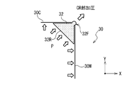
- FIG. 2 is a side view showing a configuration example in which the elastic pressing body effectively presses the corner portion of the object at the time of pressure molding.
- FIG. 3 is a side view showing a state in which reinforcing fibers are bonded to corners of a target object of an L-shaped material using the bonding apparatus of the present invention to perform pressure molding.
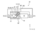
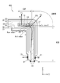
- FIG. 4 is a side view illustrating an embodiment in which a pressing unit presses a patch against a bonding site using a clamping force generated by a biasing device.
- FIG. 1 is a side view showing a state in which reinforcing fibers are joined to a corner of a target object of an L-shaped material to perform pressure molding using the joining device of the embodiment.
- FIG. 2 is a side view showing a configuration example in which the elastic pressing
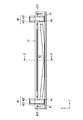
- FIG. 5 is a front view of the biasing device shown in FIG. 4 as viewed from the -X direction.
- 6 is a cross-sectional view taken along the line BB in the biasing device shown in FIG.
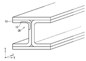
- FIG. 7 is a view showing the shape of another object to which the bonding apparatus of the embodiment can be applied.
- FIG. 8 is a side view showing a state in which a reinforcing fiber is joined to a corner of an L-shaped object and pressure molding is performed.
- FIG. 8 is a side view showing a situation in which reinforcing fibers are joined using the joining device 908 to the corners of the L-shaped object 10.
- bonding apparatus 908 is used for bonding patch 12 including reinforcing fiber 14 and matrix resin to a bonding site formed at corner portion CR in CURVE portion (bent portion) of object 10. It is an apparatus.
- the bonding device 908 includes a bag material 20, a pressure reducing port 21, a release film 22, a breather 23, a heater mat 24, and a sealant 26.
- the object 10 is a standing WEB portion (a portion extending from the bending portion to one side, and in the example shown in FIG. 8, a vertical portion) and a CAP portion (having a predetermined angle with respect to the WEB portion) A portion extending from the bending portion to the other, and in the example shown in FIG.
- the CURVE part is a part between the WEB part and the CAP part.
- the bag material 20 is a member that covers the patch 12 from the outside in a state in which the patch 12 is disposed at the bonding site at the corner of the object 10, and has airtightness.
- the bag material 20 presses the patch 12 against the object 10 using an external pressure (e.g., atmospheric pressure).
- the decompression port 21 is a port for connecting the inside of the bag material 20 and a vacuum pump (not shown).
- a vacuum pump not shown.
- the inside of the bag material 20 is decompressed.
- the external pressure presses the bag material 20 from the outside to press the patch 12 against the object 10.
- the release film 22 is a member having releasability with respect to the matrix resin and the like contained in the patch 12, and directly covers the patch 12 and the object 10.
- the breather 23 is a member for promoting the degassing inside the bag material 20.
- the breather 23 is, for example, a breathable film.
- the heater mat 24 is a device for heating the patch 12.
- the matrix resin in the patch 12 is a thermosetting resin
- the curing of the patch 12 and the adhesion to the object 10 are performed by heating.
- the heater mat 24 may include a heater that generates heat by the power from the power supply.
- the sealant 26 is a member that is disposed between the bag material 20 and the object 10 and that ensures airtightness between the outside of the bag material 20 and the inside of the bag material 20.
- cutting processing is performed on the bonding site of the object 10 as necessary to remove a damaged site.
- the patch 12 including the reinforcing fiber 14 is placed on the surface of the bonding site of the object 10. Then, the release film 22, the breather 23, the heater mat 24 and the breather 23 are sequentially disposed on the surface of the patch 12 and the object 10. Then, the sealant 26 is disposed, the pressure reducing port 21 and the vacuum pump are connected, and the inside of the bag material 20 is depressurized and degassed.
- a matrix resin is applied to the dry foam in advance, or the inside of the bag 20 is depressurized and the matrix resin is injected into the bag 20. You may Thus, the matrix resin can be impregnated into the reinforcing fibers 14.
- the heater mat 24 is energized to heat the patch 12 and the object 10.
- the inside of the bag material 20 is returned to external pressure after cooling, and the bag material 20, the release film 22, the breather 23, and the heater mat 24 are removed from the object 10.
- the finished shape (Act. Edge) of the end of the corner after joining the patch 12 is the corner part design value ( A phenomenon was observed in which the adhesive was cured in the state of coming out with respect to Nom. Edge).
- the reason why the occurrence frequency of wrinkles is high in the wrinkle generation part FW shown in FIG. 8 is that the slippage of the reinforcing fiber 14 of the patch 12 is bad in the vicinity of the wrinkle generation part FW. It is considered that, due to the poor slippage of the reinforcing fiber 14, the wrinkles generated in the reinforcing fiber 14 do not stretch and harden in a state in which slack occurs, and wrinkles are generated in the reinforcing fiber 14.
- the reinforcing fiber 14 is perpendicular to the CAP part by depressurizing the inside of the bag material 20 first (the + Y direction shown in FIG. ) Is pressed by the force of Fv (N), and a friction force ⁇ Fv (N) is generated between the reinforcing fiber 14 and the object 10.
- the frictional force ⁇ Fv makes it difficult for the reinforcing fiber 14 to slip in the X direction shown in FIG. 8, so that wrinkles remain in the wrinkle generation part FW, and wrinkles are likely to be generated.
- the force Fs for pressing in the oblique direction is based on the pressing force applied to the surface of the bag material 20 by reducing the pressure inside the bag material 20. However, it is considered that the diagonally pressing force Fs is reduced by the frictional force between the bag material 20, the release film 22, and the heater mat 24.
- the pressure in the positive X direction of the patch 12 against the reinforcing fiber 14 is insufficient at the wrinkle generating portion FW, and the wrinkles of the reinforcing fiber 14 are not stretched and are hardened, and wrinkles are easily generated.
- An experiment was conducted to bond the patch 12 under pressure. As a result of this experiment, no wrinkle was found in the reinforcing fiber 14 of the patch 12 in any of the CAP, CURVE and WEB parts.
- FIG. 1 is a side view showing a state in which reinforcing fibers are joined to a corner of a target object 10 of an L-shaped material by using a joining device 8 and pressure molding is performed.
- FIG. 2 is a side view showing a configuration example including an elastic pressing body 32 (pressure block) which effectively presses the corner portion CR of the object 10 at the time of pressure molding.
- bonding apparatus 8 presses patch 12 including reinforcing fiber 14 and matrix resin to a bonding site of a corner in CURVE portion of object 10 for bonding. It is an apparatus used when doing.
- the bonding device 8 has a bag member 20, a pressure reducing port 21, a release film 22, a breather 23, a heater mat 24, a sealant 26, and a pressing member 30.
- the pressing member 30 has a first cowl plate 30 ⁇ / b> C, a second cowl plate 30 ⁇ / b> W, and an elastic pressing body 32.
- the object 10 has, for example, a WEB unit erected vertically and a CAP unit having a predetermined angle with respect to the WEB unit.
- the CURVE portion (bent portion) is a portion between the WEB portion and the CAP portion. At the corners of the CURVE portion, there are bonding sites, and the patch 12 is bonded.
- FIG. 1 shows an example in which the angle between the WEB portion and the CAP portion is at a right angle
- the angle between the WEB portion and the CAP portion is not limited to a right angle.
- the bag material 20 is a member for covering the first cowl plate 30C, the second cowl plate 30W, the elastic pressing body 32, and the patch 12 in a state where the patch 12 is disposed at the bonding site at the corner of the object 10 is there.
- the bag material 20 is airtight, and the external pressure is used to press the first cowl plate 30C, the second cowl plate 30W and the elastic pressing body 32 against the patch 12, and the patch 12 to the object 10 Press.
- the decompression port 21 is a port for connecting the inside of the bag material 20 and a vacuum pump (not shown).
- a vacuum pump not shown.
- the inside of the bag material 20 is decompressed.
- the external pressure presses the bag material 20 from the outside to press the patch 12 against the object 10.
- the release film 22 is a member having releasability with respect to the matrix resin and the like contained in the patch 12, and directly covers the patch 12 and the object 10.
- the breather 23 is a member for promoting the degassing inside the bag material 20.
- the breather 23 is, for example, a breathable film.
- a plurality of breathers 23 are arranged.
- the breather 23 is also disposed outside the first cowl plate 30C, the second cowl plate 30W, and the elastic pressing body 32.
- the heater mat 24 is a device for heating the patch 12.
- the heater mat 24 may include a heater that generates heat by the power from the power supply.
- the matrix resin in the patch 12 is a thermosetting resin
- the curing of the patch 12 and the adhesion to the object 10 are performed by heating.
- the matrix resin of the patch 12 is a thermoplastic resin
- the patch 12 is softened by heating, and the patch 12 is cured and bonded to the object 10 by cooling thereafter.
- the heater mat 24 can also be configured to perform temperature control independently for the CAP portion, the CURVE portion, and the WEB portion.
- the heater mats 24 are disposed on both sides of the object 10 on the inner side ( ⁇ X and ⁇ Y sides shown in FIG. 1) and the outer side (+ X and + Y sides shown in FIG. 1). However, depending on the heating conditions of the patch 12, the heater mat 24 can be disposed only on either the inside or the outside of the object 10.
- the sealant 26 is a member that is disposed between the bag material 20 and the object 10 and that ensures airtightness between the outside of the bag material 20 and the inside of the bag material 20.
- the first cowl plate 30C (first plate portion) is a molding repair for pressing the patch 12 joined to the corner of the object 10 toward the CAP portion of the object 10 It is a tool.
- the first cowl plate 30C extends from the corner pressing portion 32F in the -X direction (first direction).
- the first cowl plate 30C is preferably made of a material having properties (such as elasticity) that conform to the shape of the CAP portion of the object 10 to a certain extent.
- the second cowl plate 30W (second plate portion) is a shaping jig for pressing the patch 12 joined to the corner of the object 10 toward the WEB portion of the object 10.
- the second cowl plate 30W extends from the corner pressing portion 32F in the -Y direction (the second direction whose angle is different from the first direction).
- the second cowl plate 30W preferably uses a material having properties (such as elasticity) that conform to the shape of the WEB portion of the object 10 to a certain extent.
- the first cowl plate 30C and the second cowl plate 30W are arranged at different angles along the surface shapes corresponding to the corner portion design values on both sides of the corner portion CR in the object 10. And in the state shown in FIG. 2, it has a clearance gap in the position which the 1st cowl plate 30C and the 2nd cowl plate 30W approach most.
- the WEB portion and the CAP portion have a flat plate shape, but a curved surface can also be used.
- a curved surface can also be used as the first cowl plate 30C and the second cowl plate 30W.
- the elastic pressing body 32 is disposed straddling the first cowl plate 30C and the second cowl plate 30W at a portion between the first cowl plate 30C and the second cowl plate 30W.
- a portion (corner pressing portion 32F) of the elastic pressing body 32 presses the corner portion CR of the object 10 from the gap between the first cowl plate 30C and the second cowl plate 30W. It is projected to be.
- the elastic pressing body 32 has a pressure receiving surface 32R to which a pressing force is applied on the side of the bag material 20 at a portion between the first cowl plate 30C and the second cowl plate 30W.
- the elastic pressing body 32 also has a corner pressing portion 32F that protrudes in the direction of the corner portion CR of the object 10 from the gap between the first cowl plate 30C and the second cowl plate 30W.
- the elastic pressing body 32 is a shaping jig that presses the patch 12 against the bonding site at the corner portion CR of the object 10 using the corner pressing portion 32F.
- the elastic pressing body 32 diagonally presses the patch 12 toward the corner portion CR of the object 10 with a force of Fs to strengthen the force (Fs ⁇ cos ⁇ ) larger than the frictional force ⁇ Fv of the reinforcing fiber 14 It becomes easy to add in the + X direction of 14. Then, the reinforcing fiber 14 can be slid in the + X direction shown in FIG. 1 to reduce the occurrence of wrinkles around the corner portion CR.
- the elastic pressing body 32 As a material of the elastic pressing body 32, it is preferable to use a material having a property of projecting from the gap between the first cowl plate 30C and the second cowl plate 30W by the pressing force applied from the pressure receiving surface 32R. Therefore, it is preferable to use a material having physical properties with a durometer hardness of 10 or more and 55 or less for the elastic pressing body 32. Further, since it is necessary to transmit the heat of the heater mat 24 to heat the patch 12, the elastic pressing body 32 is an elastic material (silicone rubber, nitrile rubber, ethylene, etc.) having a good thermal conductivity.
- propylene rubber chloroprene rubber, styrene butadiene rubber, polybutadiene rubber, tolyl butadiene rubber, butyl rubber, urethane rubber, natural rubber, etc.
- a highly thermally conductive high thermal conductivity material for example, aluminum powder, copper powder or the like which is a high thermal conductivity powder
- the outer shape of the corner pressing portion 32F may be a shape having a predetermined curvature, or a shape based on a corner portion design value (Nom. Edge) after joining the patch 12 of the object 10 it can.
- the lengths of the portions where the elastic pressing body 32 and the first cowl plate 30C and the elastic pressing body 32 and the second cowl plate 30W are in contact are It can be 10 to 300 mm.
- the elastic pressing body 32 and the first cowl plate 30C, and the elastic pressing body 32 and the second cowl plate 30W can be bonded in advance.
- the elastic pressure body 32 and the first cowl plate 30C can be disposed without being adhered to each other, and the elastic pressure body 32 and the second cowl plate 30W can be disposed without being adhered to each other.
- the width of the gap between the first cowl plate 30C and the second cowl plate 30W, which is a portion from which the corner pressing portion 32F protrudes, can be appropriately set in accordance with the curvature of the corner portion CR.
- the first cowl plate 30C and the second cowl plate 30W may be separate and independent members, or may be configured (integrally configured) from one member having a gap for causing the elastic pressing body 32 to protrude. Even when the first cowl plate 30C and the second cowl plate 30W are formed by one member, the shapes of the WEB portion and the CAP portion of the object 10 correspond to the mutual angle between the WEB portion and the CAP portion. Preferably, the first cowl plate 30C and the second cowl plate 30W have an elasticity that follows the shape of the object 10.
- the final shape (Act. Edge) of the corner part after patch 12 junction in corner part CR part is a corner
- the outer shape is approximately equal to the part design value (Nom. Edge) (e.g. 3.2 mm) or slightly inside.
- the reinforcing fiber 14 inside the patch 12 shown in FIG. 1 no occurrence of wrinkles or slackness was observed in any of the CAP portion (including the improvement portion CB), the CURVE portion and the WEB portion.
- organic fiber such as carbon fiber, glass fiber, aramid fiber, polyparaphenylene benzobisoxazole fiber, phenol fiber, polyethylene fiber, polyvinyl alcohol fiber, metal fiber, ceramic fiber, or a combination thereof Can be used.
- thermosetting resin for example, epoxy, phenol, vinyl ester, unsaturated polyester, cyanate ester, bismaleimide, benzoxazine and other resins can be used, and in order to cure, curing agent, curing accelerator, polymerization Initiators, catalysts, etc. can be added. Further, those to which an elastomer, rubber or the like is added can also be used.
- thermoplastic resin for example, PPS (polyphenylene sulfide), PEEK (polyether ether ketone), PEKK (polyether ketone ketone), PEK (polyether ketone), PI (polyimide), PEI (polyether imide) ), PA (nylon polyamide), etc.
- PPS polyphenylene sulfide
- PEEK polyether ether ketone
- PEKK polyether ketone ketone
- PEK polyether ketone
- PI polyimide
- PEI polyether imide
- PA nylon polyamide
- the object 10 the bag member 20, the decompression port 21, the release film 22, the breather 23, the heater mat 24, the sealant 26, and the pressing member 30 are prepared (see FIG. 1).
- the bag material 20 prepares one having the pressure reducing port 21.
- the pressing member 30 prepares one having the first cowl plate 30C, the second cowl plate 30W, and the elastic pressing body 32. Further, the corner pressing portion 32F of the pressing member 30 prepares one having a surface shape corresponding to the corner portion design value (Nom. Edge) after the patch 12 is bonded.
- the patch 12 including the reinforcing fiber 14 is placed in contact with the bonding site of the corner portion CR of the object 10. Then, the release film 22 is disposed on the patch 12, and the pressing member 30, the breather 23, the heater mat 24, and the like are appropriately disposed.
- the sealant 26 is disposed, and the bonding site of the object 10, the patch 12, the release film 22, the pressing member 30, the breather 23, and the heater mat 24 are covered with the bag material 20 using the bag material 20.
- a sealed space is formed including ten bonding sites.
- Step of pressing the corner CR When a pressing force is applied to the pressure receiving surface 32R of the elastic pressing body 32, the corner pressing portion 32F of the elastic pressing body 32 is a target from the gap between the first cowl plate 30C and the second cowl plate 30W. It projects in the direction of the corner portion CR of the object 10. Then, the corner pressing portion 32F presses the patch 12 toward the bonding site of the corner portion CR of the object 10. Then, since the reinforcing fibers 14 contained in the patch 12 are pulled toward the corner portion CR, the occurrence of wrinkles in the improvement portion CB around the corner portion CR can be reduced.
- the heater mat 24 is energized for a predetermined time to heat the object 10 and the patch 12.
- a thermosetting resin is used as the matrix resin of the patch 12, it is cured at the time of heating to bond the object 10 and the patch 12 and perform molding.
- a thermoplastic resin is used as the matrix resin of the patch 12, it is cured at the cooling after heating, and the object 10 and the patch 12 are joined and molded.
- Step of removing the bag material 20 When the molding is completed, the bag material 20, the sealant 26, the release film 22, the pressing member 30, the breather 23, and the heater mat 24 are removed. Thus, bonding of the patch 12 to the object 10 is performed.
- FIG. 3 is a side view showing a state in which reinforcing fibers are joined to a corner of the object 10 of the L-shaped material by using the joining device 18 and pressure molding is performed.
- part which has the function same as the site
- bonding device 18 is a device used when bonding patch 12 including reinforcing fiber 14 and a matrix resin to a bonding site generated at a corner of CURVE portion of object 10.
- the bonding device 18 includes a bag member 20, a decompression port 21, a release film 22, a breather 23, a heater mat 24, a sealant 26, and a pressing member 30P.
- the pressing member 30P includes a first plate portion extending from the pressing portion 30F along the CAP portion in the ⁇ X direction (first direction), and a second direction (different from the first direction from the pressing portion 30F) And a second plate portion extending along the WEB portion toward the (Y direction).
- the first plate portion of the pressing member 30P biases the patch 12 toward the CAP portion of the object 10.
- the pressing portion 30F of the pressing member 30P urges the patch 12 toward the bonding site at the corner portion CR of the object 10.
- the second plate portion of the pressing member 30P urges the patch 12 toward the WEB portion of the object 10. It is preferable to use a material having properties (such as elasticity) conforming to the shape of the object 10 for the pressing member 30P.
- biasing device 40 biases the pressing member 30P toward the joining site of the patch 12 and the object 10.
- FIG. 4 is a side view illustrating an embodiment in which the pressing unit 42T presses the patch 12 against the bonding site using the clamp force FC generated by the biasing device 40.
- FIG. 5 is a front view of the biasing device 40 shown in FIG. 4 as viewed from the -X direction.
- FIG. 6 is a cross-sectional view of the biasing device 40 shown in FIG.
- the biasing device 40 has a first biasing force applying portion 40I, a second biasing force applying portion 40E, and a biasing force applying member 42.
- the tip of the biasing force applying member 42 has a pressing portion 42T.
- the biasing device 40 also includes a tilt block 44, a slide block 43 and a back block 46.
- the first biasing force application unit 40I and the second biasing force application unit 40E apply a clamping force FC for sandwiching the biasing force application member 42 and the object 10 via the slide block 43 and the back block 46.
- the inclined block 44 shown in FIG. 4 is a triangular prism having a right triangle cross section.
- the right triangle also includes a substantially right triangle.
- the plane along the X-axis of the inclined block 44 and the plane along the Y-axis are two planes orthogonal to each other. The two surfaces are in contact with the side to be joined of the object 10.
- the inclined surface (the surface inclined with respect to the X axis and the Y axis) of the inclined block 44 has the slide block 43 and the biasing force applying member 42 in the third direction (the direction in which the pressing portion 42T is biased toward the corner portion CR) It is a sliding slope BV which is made to slide.
- the slide block 43 receives the clamp force FC in the + X direction, and slides in the corner portion CR direction (third direction) along the sliding slope BV of the inclined block 44. As a result, the clamping force FC is converted to a pressure force FD. The pressure FD is transmitted to the biasing member 42.
- the biasing force application member 42 receives the pressure force FD from the inclined block 44, slides in the direction of the corner portion CR and extends, and the pressing portion 42T applies the patch 12 to the object 10 via the bag material 20 and the like. Press (see FIG. 3).
- the component force in the direction in which the first plate portion of the pressing member 30P is urged toward the patch 12 and the second plate in the pressing member 30P can be used for the component force in the inclination direction (third direction) of the sliding slope BV. And a component in the direction of biasing the part towards the patch 12.
- the back block 46 is disposed on the back side of the target 10 with respect to the bonding site.
- the back block 46 receives the clamping force FC in the -X direction from the second biasing force application unit 40E, and transmits the clamping force FC to the object 10.
- the clamping force FC generated by the first biasing force application unit 40I and the second biasing force application unit 40E is converted into a pressing force FD, and biases the patch 12 toward the bonding site of the object 10. And pressure molding can be performed.
- FIG. 5 is a view for explaining the arrangement of the object 10 and the biasing force applying member 42 in the central portion of the object 10.
- the object 10 the bag member 20, the decompression port 21, the release film 22, the breather 23, the heater mat 24, the sealant 26, the pressing member 30P, and the biasing device 40 are prepared (see FIG. 3 to 7).
- the bag material 20 may be prepared to have a decompression port 21.
- the shape including the pressing part 30F of the pressing member 30P prepares one having a surface shape corresponding to the design value (Nom. Edge) of the corner after the object 10 and the patch 12 are joined.
- the patch 12 including the reinforcing fiber 14 is placed in contact with the bonding site of the corner portion CR of the object 10. Then, the release film 22 is disposed on the patch 12, and the pressing member 30P, the breather 23, the heater mat 24, and the like are appropriately disposed.
- the sealant 26 is disposed, and the bonding site of the object 10, the patch 12, the release film 22, the pressing member 30P, the breather 23, and the heater mat 24 are covered with the bag material 20 using the bag material 20.
- a sealed space is formed including ten bonding sites.
- Step of pressing the corner CR Next, as shown in FIGS. 4 to 6, outside the sealed space formed by the bag material and the object 10, the inclined block 44 and the biasing force application member 42 are disposed with respect to the object 10. At this time, the pressurizing unit 42T is arranged to press the patch 12 toward the corner portion CR of the object 10. Then, the slide block 43 and the back block 46 are disposed. Next, the first urging force application unit 40I and the second urging force application unit 40E are disposed. Then, the clamp force FC is applied to the slide block 43 and the back block 46. Then, the biasing force applying member 42 moves along the sliding slope BV, and the pressing unit 42T presses the patch 12 toward the corner portion CR of the object 10. Then, since the reinforcing fibers 14 contained in the patch 12 are pulled toward the corner portion CR, the occurrence of wrinkles around the corner portion CR can be reduced.
- Heating process The heater mat 24 is energized for a predetermined time to heat the object 10 and the patch 13.
- Step of removing the bag material 20 When the molding is completed, the biasing device 40, the bag material 20, the sealant 26, the release film 22, the pressing member 30P, the breather 23, and the heater mat 24 are removed. Thus, the bonding of the patch 12 to the object 10 is completed.
- FIG. 7 shows an application example to another object. Bonding of the patch 12 to the object 10 using the bonding apparatus according to the present invention is achieved by bonding the L-shaped members shown in FIG. 1 and FIG. 3 and the like and the U-shaped cross-sectional members shown in FIGS.
- the present invention is not limited to the above, and can be applied to the repair or manufacture of the bonding site at the corner portion CR of the H-shaped material shown in FIG.
- the embodiment in which the patch 12 for repair is joined to the object 10 has been described.
- the embodiments may be used to apply a patch to an object having a bonding site to manufacture various members or devices.
- the joining apparatus, the kit, the pressing member, the biasing apparatus and the joining method according to the present invention have been described above with reference to the embodiment, but the joining apparatus, the kit, the pressing member, the biasing apparatus and the joining method according to the present invention It is not limited to the embodiment.
- Various modifications can be made to the above embodiments. It is possible to combine the matters described in the above embodiment with the matters described in the other embodiments.
- the present invention can be applied to a resin transfer molding (RTM) method, a vacuum-assisted resin transfer molding (VaRTM) method, a double vacuum debulking method, an autoclave method, and other molding methods.
- the pressing member is a member for pressing the patch including the reinforcing fiber to the bonding site in the corner portion of the object
- the pressing member includes the first plate portion and the second plate portion And an elastic pressing body.
- the first plate portion and the second plate portion are disposed at different angles along the shapes on both sides of the corner portion of the object, and the corner portion is disposed between the first plate portion and the second plate portion.
- a gap is provided at a position corresponding to the part.
- the elastic pressing body is disposed across the first plate portion and the second plate portion, between the first plate portion and the second plate portion.
- a pressure receiving surface to which a pressing force is applied is provided between the first plate portion and the second plate portion opposite to the gap.
- the biasing device is a device that presses a patch including reinforcing fibers to a bonding site at a corner portion of an object.
- the biasing device includes a first biasing force applying portion, a second biasing force applying portion, and a biasing force applying member.
- the biasing force applying member has a pressing portion at its tip.
- the first biasing force application unit and the second biasing force application unit apply a clamping force for sandwiching the biasing force application member and the object.
- the pressing portion presses the patch against the bonding site.
- the biasing device may further include a tilt block, a slide block and a back block.
- the inclined block, the slide block, and the biasing force applying member are disposed on the side to be joined in the object, and the back block is disposed on the back side on the side of the region to be joined on the object.
- the tilt block has a slide slope for sliding the slide block and the biasing member in the third direction. By sliding along the sliding slope, the slide block converts a clamping force in a direction different from the third direction into a pressing force in the third direction and transmits it to the biasing force applying member.
- the pressing portion presses the patch against the bonding site by sliding along the sliding slope.
Landscapes
- Engineering & Computer Science (AREA)
- Mechanical Engineering (AREA)
- Chemical & Material Sciences (AREA)
- Composite Materials (AREA)
- Lining Or Joining Of Plastics Or The Like (AREA)
- Casting Or Compression Moulding Of Plastics Or The Like (AREA)
- Moulding By Coating Moulds (AREA)
- Folding Of Thin Sheet-Like Materials, Special Discharging Devices, And Others (AREA)
Priority Applications (5)
| Application Number | Priority Date | Filing Date | Title |
|---|---|---|---|
| EP15863240.6A EP3181339B1 (en) | 2014-11-25 | 2015-11-25 | Bonding device and bonding method |
| CA2959476A CA2959476C (en) | 2014-11-25 | 2015-11-25 | Bonding apparatus and bonding method |
| CN201580041094.XA CN106573422B (zh) | 2014-11-25 | 2015-11-25 | 接合装置和接合方法 |
| BR112017003982A BR112017003982A2 (pt) | 2014-11-25 | 2015-11-25 | aparelho de ligação, e, método de ligação para ligar um remendo contendo uma fibra de reforço em uma seção ligada de uma parte de superfície. |
| US15/507,757 US10456961B2 (en) | 2014-11-25 | 2015-11-25 | Bonding apparatus and bonding method |
Applications Claiming Priority (2)
| Application Number | Priority Date | Filing Date | Title |
|---|---|---|---|
| JP2014-238073 | 2014-11-25 | ||
| JP2014238073A JP6463094B2 (ja) | 2014-11-25 | 2014-11-25 | 接合装置及び接合方法 |
Publications (1)
| Publication Number | Publication Date |
|---|---|
| WO2016084861A1 true WO2016084861A1 (ja) | 2016-06-02 |
Family
ID=56074413
Family Applications (1)
| Application Number | Title | Priority Date | Filing Date |
|---|---|---|---|
| PCT/JP2015/083112 WO2016084861A1 (ja) | 2014-11-25 | 2015-11-25 | 接合装置と接合方法 |
Country Status (7)
Cited By (5)
| Publication number | Priority date | Publication date | Assignee | Title |
|---|---|---|---|---|
| DE102017004339A1 (de) * | 2017-05-05 | 2018-11-08 | Audi Ag | Verfahren zum Herstellen eines Faserverbundbauteils, Faserverbundbauteil für ein Kraftfahrzeug, Kraftfahrzeug mit einem Faserverbundbauteil und Vorrichtung zum Herstellen eines Faserverbundbauteils |
| US20180361690A1 (en) * | 2017-06-15 | 2018-12-20 | GM Global Technology Operations LLC | Heating elements for repair of molding defects for carbon fiber thermoplastic composites |
| US10589477B2 (en) | 2016-05-02 | 2020-03-17 | GM Global Technology Operations LLC | Cosmetic repair of a thermoplastic carbon fiber composite |
| US10695993B2 (en) | 2016-01-15 | 2020-06-30 | GM Global Technology Operations LLC | In-situ polymerization of polyamides for composite part repair |
| JP2020189409A (ja) * | 2019-05-20 | 2020-11-26 | 日産自動車株式会社 | 繊維強化樹脂製のパネル及びその成形方法 |
Families Citing this family (5)
| Publication number | Priority date | Publication date | Assignee | Title |
|---|---|---|---|---|
| US11046017B2 (en) * | 2016-11-07 | 2021-06-29 | Robert Bosch Battery Systems Llc | Device and method for forming complex joints in layered sheet material |
| JP7255025B2 (ja) * | 2020-06-17 | 2023-04-10 | 三菱重工業株式会社 | 治具及び複合材の加工方法 |
| KR102315158B1 (ko) * | 2021-05-12 | 2021-10-20 | 오시찬 | 접착물 배출장치 |
| US12011887B2 (en) | 2021-12-17 | 2024-06-18 | Rohr, Inc. | Systems and methods for thermoplastic panel manufacturing |
| WO2024163421A1 (en) * | 2023-01-31 | 2024-08-08 | Rtx Corporation | Polyimide composite repair apparatus and method via high temperature resin transfer molding |
Citations (2)
| Publication number | Priority date | Publication date | Assignee | Title |
|---|---|---|---|---|
| JP2011507738A (ja) * | 2007-12-28 | 2011-03-10 | エアバス オペラツィオンス ゲゼルシャフト ミット ベシュレンクテル ハフツング | 繊維複合材料からプロファイルを製造する方法 |
| JP2013513499A (ja) * | 2009-12-14 | 2013-04-22 | ザ・ボーイング・カンパニー | 高温複合ツール |
Family Cites Families (11)
| Publication number | Priority date | Publication date | Assignee | Title |
|---|---|---|---|---|
| FR2638673B1 (fr) * | 1988-11-08 | 1991-03-22 | Aerospatiale | Outillage pour le moulage de panneaux auto-raidis en materiau composite |
| GB9622780D0 (en) * | 1996-11-01 | 1997-01-08 | British Aerospace | Repair of composite laminates |
| US6761783B2 (en) * | 2002-04-09 | 2004-07-13 | The Boeing Company | Process method to repair bismaleimide (BMI) composite structures |
| US7604913B2 (en) * | 2004-07-16 | 2009-10-20 | Mitsubishi Chemical Corporation | Electrophotographic photosensitive body |
| US8790485B2 (en) | 2005-02-25 | 2014-07-29 | Bell Helicopter Textron Inc. | Single vacuum debulk composite panel repair |
| US7857925B2 (en) | 2007-06-15 | 2010-12-28 | The Boeing Company | Process development protocol and vacuum bag process for carbon-epoxy prepreg |
| CA2705777C (en) | 2007-11-26 | 2014-01-07 | Bell Helicopter Textron Inc. | Multi-stage debulk and compaction of thick composite repair laminates |
| JP4929147B2 (ja) | 2007-12-19 | 2012-05-09 | 三菱重工業株式会社 | 樹脂製品の修理方法 |
| DE102009001075A1 (de) * | 2009-02-23 | 2010-09-09 | Airbus Deutschland Gmbh | Verfahren zum zumindest teilweise Nachbearbeiten oder Ersetzen eines Versteifungselementes einer Faserverbundstruktur und zugehörige Anbindvorrichtung |
| IT1399682B1 (it) * | 2010-03-29 | 2013-04-26 | Alenia Aeronautica Spa | Procedimento e dispositivo per la riparazione di pannelli di materiale composito |
| US8986479B2 (en) | 2010-09-30 | 2015-03-24 | The Boeing Company | Systems and methods for on-aircraft composite repair using double vacuum debulking |
-
2014
- 2014-11-25 JP JP2014238073A patent/JP6463094B2/ja active Active
-
2015
- 2015-11-25 US US15/507,757 patent/US10456961B2/en active Active
- 2015-11-25 BR BR112017003982A patent/BR112017003982A2/pt active Search and Examination
- 2015-11-25 CA CA2959476A patent/CA2959476C/en active Active
- 2015-11-25 CN CN201580041094.XA patent/CN106573422B/zh not_active Expired - Fee Related
- 2015-11-25 WO PCT/JP2015/083112 patent/WO2016084861A1/ja active Application Filing
- 2015-11-25 EP EP15863240.6A patent/EP3181339B1/en not_active Not-in-force
Patent Citations (2)
| Publication number | Priority date | Publication date | Assignee | Title |
|---|---|---|---|---|
| JP2011507738A (ja) * | 2007-12-28 | 2011-03-10 | エアバス オペラツィオンス ゲゼルシャフト ミット ベシュレンクテル ハフツング | 繊維複合材料からプロファイルを製造する方法 |
| JP2013513499A (ja) * | 2009-12-14 | 2013-04-22 | ザ・ボーイング・カンパニー | 高温複合ツール |
Cited By (10)
| Publication number | Priority date | Publication date | Assignee | Title |
|---|---|---|---|---|
| US10695993B2 (en) | 2016-01-15 | 2020-06-30 | GM Global Technology Operations LLC | In-situ polymerization of polyamides for composite part repair |
| US10589477B2 (en) | 2016-05-02 | 2020-03-17 | GM Global Technology Operations LLC | Cosmetic repair of a thermoplastic carbon fiber composite |
| DE102017004339A1 (de) * | 2017-05-05 | 2018-11-08 | Audi Ag | Verfahren zum Herstellen eines Faserverbundbauteils, Faserverbundbauteil für ein Kraftfahrzeug, Kraftfahrzeug mit einem Faserverbundbauteil und Vorrichtung zum Herstellen eines Faserverbundbauteils |
| DE102017004339B4 (de) * | 2017-05-05 | 2021-05-12 | Audi Ag | Verfahren zum Herstellen eines Faserverbundbauteils |
| US20180361690A1 (en) * | 2017-06-15 | 2018-12-20 | GM Global Technology Operations LLC | Heating elements for repair of molding defects for carbon fiber thermoplastic composites |
| CN109109348A (zh) * | 2017-06-15 | 2019-01-01 | 通用汽车环球科技运作有限责任公司 | 用于修复碳纤维热塑性复合材料模制缺陷的加热元件 |
| US10611104B2 (en) * | 2017-06-15 | 2020-04-07 | GM Global Technology Operations LLC | Heating elements for repair of molding defects for carbon fiber thermoplastic composites |
| CN109109348B (zh) * | 2017-06-15 | 2021-06-08 | 通用汽车环球科技运作有限责任公司 | 用于修复碳纤维热塑性复合材料模制缺陷的加热元件 |
| JP2020189409A (ja) * | 2019-05-20 | 2020-11-26 | 日産自動車株式会社 | 繊維強化樹脂製のパネル及びその成形方法 |
| JP7291536B2 (ja) | 2019-05-20 | 2023-06-15 | 日産自動車株式会社 | 繊維強化樹脂製のパネル及びその成形方法 |
Also Published As
| Publication number | Publication date |
|---|---|
| BR112017003982A2 (pt) | 2017-12-12 |
| US10456961B2 (en) | 2019-10-29 |
| CA2959476A1 (en) | 2016-06-02 |
| CN106573422B (zh) | 2020-05-12 |
| EP3181339A4 (en) | 2017-09-06 |
| CA2959476C (en) | 2019-09-17 |
| EP3181339A1 (en) | 2017-06-21 |
| CN106573422A (zh) | 2017-04-19 |
| EP3181339B1 (en) | 2021-02-24 |
| JP6463094B2 (ja) | 2019-01-30 |
| JP2016097633A (ja) | 2016-05-30 |
| US20170305044A1 (en) | 2017-10-26 |
Similar Documents
| Publication | Publication Date | Title |
|---|---|---|
| WO2016084861A1 (ja) | 接合装置と接合方法 | |
| US8734711B2 (en) | Method for producing a profile from composite fiber material | |
| JP5891244B2 (ja) | 複合材半径部を圧縮する方法および装置 | |
| JP6325545B2 (ja) | フランジ付き構成要素を製造するための装置およびその製造方法 | |
| KR20200008035A (ko) | 안정화 부재를 구비한 복합 구조물 | |
| JP5148466B2 (ja) | 複合材料の修理方法 | |
| EP3392027B1 (en) | Systems and methods for assembling elongate composite structures | |
| JP6785866B2 (ja) | 複合材の成形方法及び複合材の成形用治具 | |
| JP2007118598A (ja) | プリフォームの製造方法および製造装置 | |
| CN110104202B (zh) | 使用铰接式芯轴的复合飞机制造工具 | |
| US20160346965A1 (en) | Method and tool for forming a scarf joint | |
| JP5587916B2 (ja) | 複合部品の製造方法 | |
| CN112744364B (zh) | 无真空袋复合材料修复系统及方法 | |
| EP2662203B1 (en) | Contour caul with expansion region and method for its manufacture | |
| JP6667055B2 (ja) | 複合材料成形物製造用成形型および複合材料成形物の製造方法 | |
| JP2020032581A (ja) | プリフォーム賦形方法及び複合材成形方法 | |
| JP4464208B2 (ja) | ハニカムサンドイッチパネルの製造方法 | |
| JP6724667B2 (ja) | 複合材料の成形方法および複合材料の成形装置 | |
| EP4563334A1 (en) | Molding method and molding device for composite material | |
| JP2024162802A (ja) | 賦形装置および賦形方法 | |
| WO2024048125A1 (ja) | 複合材の成形方法及び成形装置 | |
| CN114051447A (zh) | 用于由多层的基底制造t形半成品的装置和方法 | |
| JP2013199016A (ja) | 繊維強化プラスチックの製造方法 |
Legal Events
| Date | Code | Title | Description |
|---|---|---|---|
| 121 | Ep: the epo has been informed by wipo that ep was designated in this application |
Ref document number: 15863240 Country of ref document: EP Kind code of ref document: A1 |
|
| REEP | Request for entry into the european phase |
Ref document number: 2015863240 Country of ref document: EP |
|
| WWE | Wipo information: entry into national phase |
Ref document number: 2015863240 Country of ref document: EP |
|
| ENP | Entry into the national phase |
Ref document number: 2959476 Country of ref document: CA |
|
| WWE | Wipo information: entry into national phase |
Ref document number: 15507757 Country of ref document: US |
|
| REG | Reference to national code |
Ref country code: BR Ref legal event code: B01A Ref document number: 112017003982 Country of ref document: BR |
|
| NENP | Non-entry into the national phase |
Ref country code: DE |
|
| ENP | Entry into the national phase |
Ref document number: 112017003982 Country of ref document: BR Kind code of ref document: A2 Effective date: 20170224 |