WO2016084861A1 - Bonding device and bonding method - Google Patents
Bonding device and bonding method Download PDFInfo
- Publication number
- WO2016084861A1 WO2016084861A1 PCT/JP2015/083112 JP2015083112W WO2016084861A1 WO 2016084861 A1 WO2016084861 A1 WO 2016084861A1 JP 2015083112 W JP2015083112 W JP 2015083112W WO 2016084861 A1 WO2016084861 A1 WO 2016084861A1
- Authority
- WO
- WIPO (PCT)
- Prior art keywords
- patch
- bonding
- pressing
- corner
- pressing member
- Prior art date
Links
Images


Classifications
-
- B—PERFORMING OPERATIONS; TRANSPORTING
- B29—WORKING OF PLASTICS; WORKING OF SUBSTANCES IN A PLASTIC STATE IN GENERAL
- B29C—SHAPING OR JOINING OF PLASTICS; SHAPING OF MATERIAL IN A PLASTIC STATE, NOT OTHERWISE PROVIDED FOR; AFTER-TREATMENT OF THE SHAPED PRODUCTS, e.g. REPAIRING
- B29C43/00—Compression moulding, i.e. applying external pressure to flow the moulding material; Apparatus therefor
- B29C43/02—Compression moulding, i.e. applying external pressure to flow the moulding material; Apparatus therefor of articles of definite length, i.e. discrete articles
- B29C43/10—Isostatic pressing, i.e. using non-rigid pressure-exerting members against rigid parts or dies
- B29C43/12—Isostatic pressing, i.e. using non-rigid pressure-exerting members against rigid parts or dies using bags surrounding the moulding material or using membranes contacting the moulding material
-
- B—PERFORMING OPERATIONS; TRANSPORTING
- B29—WORKING OF PLASTICS; WORKING OF SUBSTANCES IN A PLASTIC STATE IN GENERAL
- B29C—SHAPING OR JOINING OF PLASTICS; SHAPING OF MATERIAL IN A PLASTIC STATE, NOT OTHERWISE PROVIDED FOR; AFTER-TREATMENT OF THE SHAPED PRODUCTS, e.g. REPAIRING
- B29C43/00—Compression moulding, i.e. applying external pressure to flow the moulding material; Apparatus therefor
- B29C43/32—Component parts, details or accessories; Auxiliary operations
- B29C43/36—Moulds for making articles of definite length, i.e. discrete articles
- B29C43/3642—Bags, bleeder sheets or cauls for isostatic pressing
-
- B—PERFORMING OPERATIONS; TRANSPORTING
- B29—WORKING OF PLASTICS; WORKING OF SUBSTANCES IN A PLASTIC STATE IN GENERAL
- B29C—SHAPING OR JOINING OF PLASTICS; SHAPING OF MATERIAL IN A PLASTIC STATE, NOT OTHERWISE PROVIDED FOR; AFTER-TREATMENT OF THE SHAPED PRODUCTS, e.g. REPAIRING
- B29C65/00—Joining or sealing of preformed parts, e.g. welding of plastics materials; Apparatus therefor
- B29C65/02—Joining or sealing of preformed parts, e.g. welding of plastics materials; Apparatus therefor by heating, with or without pressure
-
- B—PERFORMING OPERATIONS; TRANSPORTING
- B29—WORKING OF PLASTICS; WORKING OF SUBSTANCES IN A PLASTIC STATE IN GENERAL
- B29C—SHAPING OR JOINING OF PLASTICS; SHAPING OF MATERIAL IN A PLASTIC STATE, NOT OTHERWISE PROVIDED FOR; AFTER-TREATMENT OF THE SHAPED PRODUCTS, e.g. REPAIRING
- B29C65/00—Joining or sealing of preformed parts, e.g. welding of plastics materials; Apparatus therefor
- B29C65/48—Joining or sealing of preformed parts, e.g. welding of plastics materials; Apparatus therefor using adhesives, i.e. using supplementary joining material; solvent bonding
-
- B—PERFORMING OPERATIONS; TRANSPORTING
- B29—WORKING OF PLASTICS; WORKING OF SUBSTANCES IN A PLASTIC STATE IN GENERAL
- B29C—SHAPING OR JOINING OF PLASTICS; SHAPING OF MATERIAL IN A PLASTIC STATE, NOT OTHERWISE PROVIDED FOR; AFTER-TREATMENT OF THE SHAPED PRODUCTS, e.g. REPAIRING
- B29C65/00—Joining or sealing of preformed parts, e.g. welding of plastics materials; Apparatus therefor
- B29C65/78—Means for handling the parts to be joined, e.g. for making containers or hollow articles, e.g. means for handling sheets, plates, web-like materials, tubular articles, hollow articles or elements to be joined therewith; Means for discharging the joined articles from the joining apparatus
- B29C65/7841—Holding or clamping means for handling purposes
-
- B—PERFORMING OPERATIONS; TRANSPORTING
- B29—WORKING OF PLASTICS; WORKING OF SUBSTANCES IN A PLASTIC STATE IN GENERAL
- B29C—SHAPING OR JOINING OF PLASTICS; SHAPING OF MATERIAL IN A PLASTIC STATE, NOT OTHERWISE PROVIDED FOR; AFTER-TREATMENT OF THE SHAPED PRODUCTS, e.g. REPAIRING
- B29C66/00—General aspects of processes or apparatus for joining preformed parts
- B29C66/004—Preventing sticking together, e.g. of some areas of the parts to be joined
- B29C66/0042—Preventing sticking together, e.g. of some areas of the parts to be joined of the joining tool and the parts to be joined
- B29C66/0044—Preventing sticking together, e.g. of some areas of the parts to be joined of the joining tool and the parts to be joined using a separating sheet, e.g. fixed on the joining tool
-
- B—PERFORMING OPERATIONS; TRANSPORTING
- B29—WORKING OF PLASTICS; WORKING OF SUBSTANCES IN A PLASTIC STATE IN GENERAL
- B29C—SHAPING OR JOINING OF PLASTICS; SHAPING OF MATERIAL IN A PLASTIC STATE, NOT OTHERWISE PROVIDED FOR; AFTER-TREATMENT OF THE SHAPED PRODUCTS, e.g. REPAIRING
- B29C66/00—General aspects of processes or apparatus for joining preformed parts
- B29C66/01—General aspects dealing with the joint area or with the area to be joined
- B29C66/05—Particular design of joint configurations
- B29C66/10—Particular design of joint configurations particular design of the joint cross-sections
- B29C66/11—Joint cross-sections comprising a single joint-segment, i.e. one of the parts to be joined comprising a single joint-segment in the joint cross-section
- B29C66/112—Single lapped joints
- B29C66/1122—Single lap to lap joints, i.e. overlap joints
-
- B—PERFORMING OPERATIONS; TRANSPORTING
- B29—WORKING OF PLASTICS; WORKING OF SUBSTANCES IN A PLASTIC STATE IN GENERAL
- B29C—SHAPING OR JOINING OF PLASTICS; SHAPING OF MATERIAL IN A PLASTIC STATE, NOT OTHERWISE PROVIDED FOR; AFTER-TREATMENT OF THE SHAPED PRODUCTS, e.g. REPAIRING
- B29C66/00—General aspects of processes or apparatus for joining preformed parts
- B29C66/50—General aspects of joining tubular articles; General aspects of joining long products, i.e. bars or profiled elements; General aspects of joining single elements to tubular articles, hollow articles or bars; General aspects of joining several hollow-preforms to form hollow or tubular articles
- B29C66/51—Joining tubular articles, profiled elements or bars; Joining single elements to tubular articles, hollow articles or bars; Joining several hollow-preforms to form hollow or tubular articles
- B29C66/53—Joining single elements to tubular articles, hollow articles or bars
- B29C66/532—Joining single elements to the wall of tubular articles, hollow articles or bars
- B29C66/5326—Joining single elements to the wall of tubular articles, hollow articles or bars said single elements being substantially flat
-
- B—PERFORMING OPERATIONS; TRANSPORTING
- B29—WORKING OF PLASTICS; WORKING OF SUBSTANCES IN A PLASTIC STATE IN GENERAL
- B29C—SHAPING OR JOINING OF PLASTICS; SHAPING OF MATERIAL IN A PLASTIC STATE, NOT OTHERWISE PROVIDED FOR; AFTER-TREATMENT OF THE SHAPED PRODUCTS, e.g. REPAIRING
- B29C66/00—General aspects of processes or apparatus for joining preformed parts
- B29C66/70—General aspects of processes or apparatus for joining preformed parts characterised by the composition, physical properties or the structure of the material of the parts to be joined; Joining with non-plastics material
- B29C66/72—General aspects of processes or apparatus for joining preformed parts characterised by the composition, physical properties or the structure of the material of the parts to be joined; Joining with non-plastics material characterised by the structure of the material of the parts to be joined
- B29C66/721—Fibre-reinforced materials
-
- B—PERFORMING OPERATIONS; TRANSPORTING
- B29—WORKING OF PLASTICS; WORKING OF SUBSTANCES IN A PLASTIC STATE IN GENERAL
- B29C—SHAPING OR JOINING OF PLASTICS; SHAPING OF MATERIAL IN A PLASTIC STATE, NOT OTHERWISE PROVIDED FOR; AFTER-TREATMENT OF THE SHAPED PRODUCTS, e.g. REPAIRING
- B29C66/00—General aspects of processes or apparatus for joining preformed parts
- B29C66/80—General aspects of machine operations or constructions and parts thereof
- B29C66/81—General aspects of the pressing elements, i.e. the elements applying pressure on the parts to be joined in the area to be joined, e.g. the welding jaws or clamps
- B29C66/814—General aspects of the pressing elements, i.e. the elements applying pressure on the parts to be joined in the area to be joined, e.g. the welding jaws or clamps characterised by the design of the pressing elements, e.g. of the welding jaws or clamps
- B29C66/8141—General aspects of the pressing elements, i.e. the elements applying pressure on the parts to be joined in the area to be joined, e.g. the welding jaws or clamps characterised by the design of the pressing elements, e.g. of the welding jaws or clamps characterised by the surface geometry of the part of the pressing elements, e.g. welding jaws or clamps, coming into contact with the parts to be joined
- B29C66/81411—General aspects of the pressing elements, i.e. the elements applying pressure on the parts to be joined in the area to be joined, e.g. the welding jaws or clamps characterised by the design of the pressing elements, e.g. of the welding jaws or clamps characterised by the surface geometry of the part of the pressing elements, e.g. welding jaws or clamps, coming into contact with the parts to be joined characterised by its cross-section, e.g. transversal or longitudinal, being non-flat
- B29C66/81415—General aspects of the pressing elements, i.e. the elements applying pressure on the parts to be joined in the area to be joined, e.g. the welding jaws or clamps characterised by the design of the pressing elements, e.g. of the welding jaws or clamps characterised by the surface geometry of the part of the pressing elements, e.g. welding jaws or clamps, coming into contact with the parts to be joined characterised by its cross-section, e.g. transversal or longitudinal, being non-flat being bevelled
- B29C66/81417—General aspects of the pressing elements, i.e. the elements applying pressure on the parts to be joined in the area to be joined, e.g. the welding jaws or clamps characterised by the design of the pressing elements, e.g. of the welding jaws or clamps characterised by the surface geometry of the part of the pressing elements, e.g. welding jaws or clamps, coming into contact with the parts to be joined characterised by its cross-section, e.g. transversal or longitudinal, being non-flat being bevelled being V-shaped
-
- B—PERFORMING OPERATIONS; TRANSPORTING
- B29—WORKING OF PLASTICS; WORKING OF SUBSTANCES IN A PLASTIC STATE IN GENERAL
- B29C—SHAPING OR JOINING OF PLASTICS; SHAPING OF MATERIAL IN A PLASTIC STATE, NOT OTHERWISE PROVIDED FOR; AFTER-TREATMENT OF THE SHAPED PRODUCTS, e.g. REPAIRING
- B29C66/00—General aspects of processes or apparatus for joining preformed parts
- B29C66/80—General aspects of machine operations or constructions and parts thereof
- B29C66/81—General aspects of the pressing elements, i.e. the elements applying pressure on the parts to be joined in the area to be joined, e.g. the welding jaws or clamps
- B29C66/814—General aspects of the pressing elements, i.e. the elements applying pressure on the parts to be joined in the area to be joined, e.g. the welding jaws or clamps characterised by the design of the pressing elements, e.g. of the welding jaws or clamps
- B29C66/8145—General aspects of the pressing elements, i.e. the elements applying pressure on the parts to be joined in the area to be joined, e.g. the welding jaws or clamps characterised by the design of the pressing elements, e.g. of the welding jaws or clamps characterised by the constructional aspects of the pressing elements, e.g. of the welding jaws or clamps
- B29C66/81455—General aspects of the pressing elements, i.e. the elements applying pressure on the parts to be joined in the area to be joined, e.g. the welding jaws or clamps characterised by the design of the pressing elements, e.g. of the welding jaws or clamps characterised by the constructional aspects of the pressing elements, e.g. of the welding jaws or clamps being a fluid inflatable bag or bladder, a diaphragm or a vacuum bag for applying isostatic pressure
-
- B—PERFORMING OPERATIONS; TRANSPORTING
- B29—WORKING OF PLASTICS; WORKING OF SUBSTANCES IN A PLASTIC STATE IN GENERAL
- B29C—SHAPING OR JOINING OF PLASTICS; SHAPING OF MATERIAL IN A PLASTIC STATE, NOT OTHERWISE PROVIDED FOR; AFTER-TREATMENT OF THE SHAPED PRODUCTS, e.g. REPAIRING
- B29C70/00—Shaping composites, i.e. plastics material comprising reinforcements, fillers or preformed parts, e.g. inserts
- B29C70/04—Shaping composites, i.e. plastics material comprising reinforcements, fillers or preformed parts, e.g. inserts comprising reinforcements only, e.g. self-reinforcing plastics
- B29C70/06—Fibrous reinforcements only
-
- B—PERFORMING OPERATIONS; TRANSPORTING
- B29—WORKING OF PLASTICS; WORKING OF SUBSTANCES IN A PLASTIC STATE IN GENERAL
- B29C—SHAPING OR JOINING OF PLASTICS; SHAPING OF MATERIAL IN A PLASTIC STATE, NOT OTHERWISE PROVIDED FOR; AFTER-TREATMENT OF THE SHAPED PRODUCTS, e.g. REPAIRING
- B29C73/00—Repairing of articles made from plastics or substances in a plastic state, e.g. of articles shaped or produced by using techniques covered by this subclass or subclass B29D
- B29C73/04—Repairing of articles made from plastics or substances in a plastic state, e.g. of articles shaped or produced by using techniques covered by this subclass or subclass B29D using preformed elements
- B29C73/10—Repairing of articles made from plastics or substances in a plastic state, e.g. of articles shaped or produced by using techniques covered by this subclass or subclass B29D using preformed elements using patches sealing on the surface of the article
- B29C73/12—Apparatus therefor, e.g. for applying
-
- B—PERFORMING OPERATIONS; TRANSPORTING
- B29—WORKING OF PLASTICS; WORKING OF SUBSTANCES IN A PLASTIC STATE IN GENERAL
- B29C—SHAPING OR JOINING OF PLASTICS; SHAPING OF MATERIAL IN A PLASTIC STATE, NOT OTHERWISE PROVIDED FOR; AFTER-TREATMENT OF THE SHAPED PRODUCTS, e.g. REPAIRING
- B29C73/00—Repairing of articles made from plastics or substances in a plastic state, e.g. of articles shaped or produced by using techniques covered by this subclass or subclass B29D
- B29C73/24—Apparatus or accessories not otherwise provided for
- B29C73/30—Apparatus or accessories not otherwise provided for for local pressing or local heating
- B29C73/32—Apparatus or accessories not otherwise provided for for local pressing or local heating using an elastic element, e.g. inflatable bag
-
- B—PERFORMING OPERATIONS; TRANSPORTING
- B29—WORKING OF PLASTICS; WORKING OF SUBSTANCES IN A PLASTIC STATE IN GENERAL
- B29C—SHAPING OR JOINING OF PLASTICS; SHAPING OF MATERIAL IN A PLASTIC STATE, NOT OTHERWISE PROVIDED FOR; AFTER-TREATMENT OF THE SHAPED PRODUCTS, e.g. REPAIRING
- B29C43/00—Compression moulding, i.e. applying external pressure to flow the moulding material; Apparatus therefor
- B29C43/32—Component parts, details or accessories; Auxiliary operations
- B29C43/36—Moulds for making articles of definite length, i.e. discrete articles
- B29C43/3642—Bags, bleeder sheets or cauls for isostatic pressing
- B29C2043/3644—Vacuum bags; Details thereof, e.g. fixing or clamping
-
- B—PERFORMING OPERATIONS; TRANSPORTING
- B29—WORKING OF PLASTICS; WORKING OF SUBSTANCES IN A PLASTIC STATE IN GENERAL
- B29C—SHAPING OR JOINING OF PLASTICS; SHAPING OF MATERIAL IN A PLASTIC STATE, NOT OTHERWISE PROVIDED FOR; AFTER-TREATMENT OF THE SHAPED PRODUCTS, e.g. REPAIRING
- B29C65/00—Joining or sealing of preformed parts, e.g. welding of plastics materials; Apparatus therefor
- B29C65/02—Joining or sealing of preformed parts, e.g. welding of plastics materials; Apparatus therefor by heating, with or without pressure
- B29C65/18—Joining or sealing of preformed parts, e.g. welding of plastics materials; Apparatus therefor by heating, with or without pressure using heated tools
-
- B—PERFORMING OPERATIONS; TRANSPORTING
- B29—WORKING OF PLASTICS; WORKING OF SUBSTANCES IN A PLASTIC STATE IN GENERAL
- B29C—SHAPING OR JOINING OF PLASTICS; SHAPING OF MATERIAL IN A PLASTIC STATE, NOT OTHERWISE PROVIDED FOR; AFTER-TREATMENT OF THE SHAPED PRODUCTS, e.g. REPAIRING
- B29C65/00—Joining or sealing of preformed parts, e.g. welding of plastics materials; Apparatus therefor
- B29C65/48—Joining or sealing of preformed parts, e.g. welding of plastics materials; Apparatus therefor using adhesives, i.e. using supplementary joining material; solvent bonding
- B29C65/4805—Joining or sealing of preformed parts, e.g. welding of plastics materials; Apparatus therefor using adhesives, i.e. using supplementary joining material; solvent bonding characterised by the type of adhesives
- B29C65/481—Non-reactive adhesives, e.g. physically hardening adhesives
- B29C65/4815—Hot melt adhesives, e.g. thermoplastic adhesives
-
- B—PERFORMING OPERATIONS; TRANSPORTING
- B29—WORKING OF PLASTICS; WORKING OF SUBSTANCES IN A PLASTIC STATE IN GENERAL
- B29C—SHAPING OR JOINING OF PLASTICS; SHAPING OF MATERIAL IN A PLASTIC STATE, NOT OTHERWISE PROVIDED FOR; AFTER-TREATMENT OF THE SHAPED PRODUCTS, e.g. REPAIRING
- B29C65/00—Joining or sealing of preformed parts, e.g. welding of plastics materials; Apparatus therefor
- B29C65/48—Joining or sealing of preformed parts, e.g. welding of plastics materials; Apparatus therefor using adhesives, i.e. using supplementary joining material; solvent bonding
- B29C65/4805—Joining or sealing of preformed parts, e.g. welding of plastics materials; Apparatus therefor using adhesives, i.e. using supplementary joining material; solvent bonding characterised by the type of adhesives
- B29C65/483—Reactive adhesives, e.g. chemically curing adhesives
- B29C65/4835—Heat curing adhesives
-
- B—PERFORMING OPERATIONS; TRANSPORTING
- B29—WORKING OF PLASTICS; WORKING OF SUBSTANCES IN A PLASTIC STATE IN GENERAL
- B29C—SHAPING OR JOINING OF PLASTICS; SHAPING OF MATERIAL IN A PLASTIC STATE, NOT OTHERWISE PROVIDED FOR; AFTER-TREATMENT OF THE SHAPED PRODUCTS, e.g. REPAIRING
- B29C65/00—Joining or sealing of preformed parts, e.g. welding of plastics materials; Apparatus therefor
- B29C65/78—Means for handling the parts to be joined, e.g. for making containers or hollow articles, e.g. means for handling sheets, plates, web-like materials, tubular articles, hollow articles or elements to be joined therewith; Means for discharging the joined articles from the joining apparatus
-
- B—PERFORMING OPERATIONS; TRANSPORTING
- B29—WORKING OF PLASTICS; WORKING OF SUBSTANCES IN A PLASTIC STATE IN GENERAL
- B29C—SHAPING OR JOINING OF PLASTICS; SHAPING OF MATERIAL IN A PLASTIC STATE, NOT OTHERWISE PROVIDED FOR; AFTER-TREATMENT OF THE SHAPED PRODUCTS, e.g. REPAIRING
- B29C66/00—General aspects of processes or apparatus for joining preformed parts
- B29C66/70—General aspects of processes or apparatus for joining preformed parts characterised by the composition, physical properties or the structure of the material of the parts to be joined; Joining with non-plastics material
- B29C66/73—General aspects of processes or apparatus for joining preformed parts characterised by the composition, physical properties or the structure of the material of the parts to be joined; Joining with non-plastics material characterised by the intensive physical properties of the material of the parts to be joined, by the optical properties of the material of the parts to be joined, by the extensive physical properties of the parts to be joined, by the state of the material of the parts to be joined or by the material of the parts to be joined being a thermoplastic or a thermoset
- B29C66/737—General aspects of processes or apparatus for joining preformed parts characterised by the composition, physical properties or the structure of the material of the parts to be joined; Joining with non-plastics material characterised by the intensive physical properties of the material of the parts to be joined, by the optical properties of the material of the parts to be joined, by the extensive physical properties of the parts to be joined, by the state of the material of the parts to be joined or by the material of the parts to be joined being a thermoplastic or a thermoset characterised by the state of the material of the parts to be joined
- B29C66/7375—General aspects of processes or apparatus for joining preformed parts characterised by the composition, physical properties or the structure of the material of the parts to be joined; Joining with non-plastics material characterised by the intensive physical properties of the material of the parts to be joined, by the optical properties of the material of the parts to be joined, by the extensive physical properties of the parts to be joined, by the state of the material of the parts to be joined or by the material of the parts to be joined being a thermoplastic or a thermoset characterised by the state of the material of the parts to be joined uncured, partially cured or fully cured
- B29C66/73751—General aspects of processes or apparatus for joining preformed parts characterised by the composition, physical properties or the structure of the material of the parts to be joined; Joining with non-plastics material characterised by the intensive physical properties of the material of the parts to be joined, by the optical properties of the material of the parts to be joined, by the extensive physical properties of the parts to be joined, by the state of the material of the parts to be joined or by the material of the parts to be joined being a thermoplastic or a thermoset characterised by the state of the material of the parts to be joined uncured, partially cured or fully cured the to-be-joined area of at least one of the parts to be joined being uncured, i.e. non cross-linked, non vulcanized
-
- B—PERFORMING OPERATIONS; TRANSPORTING
- B29—WORKING OF PLASTICS; WORKING OF SUBSTANCES IN A PLASTIC STATE IN GENERAL
- B29C—SHAPING OR JOINING OF PLASTICS; SHAPING OF MATERIAL IN A PLASTIC STATE, NOT OTHERWISE PROVIDED FOR; AFTER-TREATMENT OF THE SHAPED PRODUCTS, e.g. REPAIRING
- B29C66/00—General aspects of processes or apparatus for joining preformed parts
- B29C66/70—General aspects of processes or apparatus for joining preformed parts characterised by the composition, physical properties or the structure of the material of the parts to be joined; Joining with non-plastics material
- B29C66/73—General aspects of processes or apparatus for joining preformed parts characterised by the composition, physical properties or the structure of the material of the parts to be joined; Joining with non-plastics material characterised by the intensive physical properties of the material of the parts to be joined, by the optical properties of the material of the parts to be joined, by the extensive physical properties of the parts to be joined, by the state of the material of the parts to be joined or by the material of the parts to be joined being a thermoplastic or a thermoset
- B29C66/739—General aspects of processes or apparatus for joining preformed parts characterised by the composition, physical properties or the structure of the material of the parts to be joined; Joining with non-plastics material characterised by the intensive physical properties of the material of the parts to be joined, by the optical properties of the material of the parts to be joined, by the extensive physical properties of the parts to be joined, by the state of the material of the parts to be joined or by the material of the parts to be joined being a thermoplastic or a thermoset characterised by the material of the parts to be joined being a thermoplastic or a thermoset
- B29C66/7392—General aspects of processes or apparatus for joining preformed parts characterised by the composition, physical properties or the structure of the material of the parts to be joined; Joining with non-plastics material characterised by the intensive physical properties of the material of the parts to be joined, by the optical properties of the material of the parts to be joined, by the extensive physical properties of the parts to be joined, by the state of the material of the parts to be joined or by the material of the parts to be joined being a thermoplastic or a thermoset characterised by the material of the parts to be joined being a thermoplastic or a thermoset characterised by the material of at least one of the parts being a thermoplastic
-
- B—PERFORMING OPERATIONS; TRANSPORTING
- B29—WORKING OF PLASTICS; WORKING OF SUBSTANCES IN A PLASTIC STATE IN GENERAL
- B29C—SHAPING OR JOINING OF PLASTICS; SHAPING OF MATERIAL IN A PLASTIC STATE, NOT OTHERWISE PROVIDED FOR; AFTER-TREATMENT OF THE SHAPED PRODUCTS, e.g. REPAIRING
- B29C66/00—General aspects of processes or apparatus for joining preformed parts
- B29C66/70—General aspects of processes or apparatus for joining preformed parts characterised by the composition, physical properties or the structure of the material of the parts to be joined; Joining with non-plastics material
- B29C66/73—General aspects of processes or apparatus for joining preformed parts characterised by the composition, physical properties or the structure of the material of the parts to be joined; Joining with non-plastics material characterised by the intensive physical properties of the material of the parts to be joined, by the optical properties of the material of the parts to be joined, by the extensive physical properties of the parts to be joined, by the state of the material of the parts to be joined or by the material of the parts to be joined being a thermoplastic or a thermoset
- B29C66/739—General aspects of processes or apparatus for joining preformed parts characterised by the composition, physical properties or the structure of the material of the parts to be joined; Joining with non-plastics material characterised by the intensive physical properties of the material of the parts to be joined, by the optical properties of the material of the parts to be joined, by the extensive physical properties of the parts to be joined, by the state of the material of the parts to be joined or by the material of the parts to be joined being a thermoplastic or a thermoset characterised by the material of the parts to be joined being a thermoplastic or a thermoset
- B29C66/7394—General aspects of processes or apparatus for joining preformed parts characterised by the composition, physical properties or the structure of the material of the parts to be joined; Joining with non-plastics material characterised by the intensive physical properties of the material of the parts to be joined, by the optical properties of the material of the parts to be joined, by the extensive physical properties of the parts to be joined, by the state of the material of the parts to be joined or by the material of the parts to be joined being a thermoplastic or a thermoset characterised by the material of the parts to be joined being a thermoplastic or a thermoset characterised by the material of at least one of the parts being a thermoset
-
- B—PERFORMING OPERATIONS; TRANSPORTING
- B29—WORKING OF PLASTICS; WORKING OF SUBSTANCES IN A PLASTIC STATE IN GENERAL
- B29C—SHAPING OR JOINING OF PLASTICS; SHAPING OF MATERIAL IN A PLASTIC STATE, NOT OTHERWISE PROVIDED FOR; AFTER-TREATMENT OF THE SHAPED PRODUCTS, e.g. REPAIRING
- B29C73/00—Repairing of articles made from plastics or substances in a plastic state, e.g. of articles shaped or produced by using techniques covered by this subclass or subclass B29D
- B29C73/02—Repairing of articles made from plastics or substances in a plastic state, e.g. of articles shaped or produced by using techniques covered by this subclass or subclass B29D using liquid or paste-like material
- B29C73/025—Repairing of articles made from plastics or substances in a plastic state, e.g. of articles shaped or produced by using techniques covered by this subclass or subclass B29D using liquid or paste-like material fed under pressure
Definitions
- the present invention relates to a bonding apparatus and a bonding method used when bonding a patch to an inner corner (hereinafter referred to as a corner) or a recess of an object.
- a laminate of fibers impregnated with resin in advance is formed, heated at a first temperature, and depressurized to cure the resin.
- a degassed impregnated laminate is placed over the area of the composite to be repaired, heated at a second temperature, and depressurized to cure the impregnated laminate over the area to be repaired.
- Patent Document 2 discloses a method for repairing an airframe structure having a flat surface or a curved surface on board by a dual vacuum debulking system. .
- the dual vacuum debulking system described in Patent Document 2 includes an outer bagging film covering an area to be repaired, and a strong back support disposed between the outer bagging film and a parent structure.
- the shape of the strongback support has a contour that matches the contour of the parent structure encountered.
- Patent Document 3 discloses an invention related to a process of determining parameters in a pretreatment process of a composite patch for repair using dual vacuum bag processing. .
- Patent Document 4 discloses a method of repairing a damaged composite part having an exposed surface.
- the method of producing a laminate made from a polymer matrix composite described in Patent Document 4 places a release film on the surface of a damaged composite and is uncured to conform to the contour of the surface of the damaged composite. Form a stack assembly of layers and heat and suction below the curing temperature. Thereafter, the stack assembly of the uncured layer is removed, an adhesive is applied to the exposed surface of the damaged composite, and then the stack assembly of the uncured layer is placed and compression cured.
- An object of the present invention is to provide a bonding apparatus and a bonding method for bonding a patch containing reinforcing fibers to a corner or a recess of an object.
- the bonding device is a device for bonding a patch including reinforcing fibers to a bonding site of a surface portion of a corner portion of an object.
- the bonding apparatus includes a pressing member and a biasing unit.
- the pressing member presses the surface of the bonded patch in response to the applied force.
- the biasing unit applies an application force to the pressing member.
- the pressing member is a first plate portion extending in the first direction along the object from the corner portion, and a second plate extending in the second direction different from the first direction along the object from the corner portion And 2 plate portions. The object is pressed by the first plate portion and the second plate portion in response to the applied force.
- the pressing member is a first plate portion extending in the first direction along the object from the corner portion, and a second plate extending in the second direction different from the first direction along the object from the corner portion A two-plate portion, and an elastic pressing body that presses the corner portion through between the first and second plate portions.
- the elastic pressing body presses the corner portion through a gap between the first plate portion and the second plate portion in response to the pressure receiving surface to which the application force is applied, and the application force.
- a pressurizing unit is a pressurizing unit.
- the durometer hardness of the elastic pressing body is 10 or more and 55 or less.
- a high thermal conductivity material can be added to the elastic pressurizer.
- the apparatus further includes a heating device for heating the patch, and a bag material covering the surface portion including the bonding site of the object, the patch, the heating device, and the pressing member.
- a heating device for heating the patch
- a bag material covering the surface portion including the bonding site of the object, the patch, the heating device, and the pressing member.
- atmospheric pressure acting on the pressure receiving surface at least through the bag material can be used.
- the apparatus further comprises a heating device for heating a patch, and the surface portion including the bonding site of the object, the patch, the heating device, and a bag material covering the pressing member.
- the inside of the bag material is depressurized, and the biasing portion is disposed outside a sealed space formed by the bag material and the object, and biases the pressing member toward the patch.
- the biasing device has a biasing member that applies a pressing force along the third direction.
- the third direction is a direction in which the pressing portion is biased toward the corner portion, and a component force in the third direction is a component force in the direction of biasing the first plate portion toward the patch, and A component in the direction of biasing the plate towards the patch is included.
- the biasing device further comprises a tilt block and a slide block.
- the tilt block has a slide slope for sliding the slide block and the biasing member in the third direction. By sliding along the sliding slope, the slide block converts a clamping force in a direction different from the third direction into a pressing force in the third direction and transmits it to the biasing force applying member.
- the biasing force application member applies a pressing force to the pressing member via the bag material by sliding along the sliding slope.
- the tilt block, the slide block and the biasing member of the biasing device are disposed on the side of the object to be joined.
- the biasing device has a back block on the back side of the bonding site side of the object.
- the bonding method using the bonding apparatus according to the present invention is a method of bonding a patch including reinforcing fibers to the surface portion of the corner of an object having a bonding site at the corner.
- the bonding method according to the present invention comprises the steps of preparing a bag material having a decompression port, a heating device, and a pressing member having a pressing portion for pressing the surface shape of the patch corresponding to the corner portion design value after patch bonding. Have.
- the method further includes the step of disposing the patch such that the patch is in contact with the bonding site of the corner portion of the object.
- the method further includes the step of arranging the pressing member such that the pressing portion is in contact with the bonded portion of the corner portion. Further, it is a step of forming a sealed space by the bag material and the object, and has a step of forming the sealed space so that the patch, the heating device, and the pressing member are disposed in the sealed space.
- the method further includes the steps of degassing the gas in the enclosed space via the decompression port, and pressing the pressing portion of the pressing member toward the corner portion via the patch. And it has the process of heating and joining an object and a patch with a heating device, and shape
- the pressing member according to the present invention is a member for pressing a patch including a reinforcing fiber to a bonding site in a corner portion of an object.
- the pressing member has a first plate portion, a second plate portion, and an elastic pressing body.
- the first plate portion and the second plate portion are disposed at different angles along the shapes on both sides of the corner portion of the object, and the corner portion is formed between the first plate portion and the second plate portion.
- a gap is provided at the position corresponding to.
- the elastic pressing body is disposed across the first plate portion and the second plate portion, between the first plate portion and the second plate portion. Further, the elastic pressing body has a pressure receiving surface to which a pressing force is applied on the side opposite to the gap. The elastic pressing body has a pressing portion that presses the patch on the bonding site by receiving the pressing force and protruding from the gap in the direction of the corner portion of the object.
- the biasing device is a device for pressing a patch including reinforcing fibers against a bonding site at a corner of an object.
- the biasing device includes a first biasing force applying portion, a second biasing force applying portion, and a biasing force applying member.
- the biasing force applying member has a pressing portion at its tip.
- the first biasing force application unit and the second biasing force application unit apply a clamping force for sandwiching the biasing force application member and the object. Then, based on the clamping force, the biasing portion extends in the direction of the corner portion of the object, whereby the pressing portion presses the patch against the bonding site.
- the biasing device of the present invention further comprises a tilt block, a slide block and a back block.
- the tilt block, the slide block, and the biasing member are disposed on the side of the object to be joined.
- the back block is disposed on the back side of the bonding site side of the object.
- the tilt block has a slide slope for sliding the slide block and the biasing member in the third direction. By sliding along the sliding slope, the slide block converts a clamping force in a direction different from the third direction into a pressing force in the third direction and transmits it to the biasing force applying member.
- the pressing portion presses the patch against the bonding site by sliding along the sliding slope.
- the patch including the reinforcing fiber is effectively pressed against the corner or the recess of the object to reduce the generation of wrinkles It can be done.
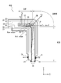
- FIG. 1 is a side view showing a state in which reinforcing fibers are joined to a corner of a target object of an L-shaped material to perform pressure molding using the joining device of the embodiment.
- FIG. 2 is a side view showing a configuration example in which the elastic pressing body effectively presses the corner portion of the object at the time of pressure molding.
- FIG. 3 is a side view showing a state in which reinforcing fibers are bonded to corners of a target object of an L-shaped material using the bonding apparatus of the present invention to perform pressure molding.
- FIG. 4 is a side view illustrating an embodiment in which a pressing unit presses a patch against a bonding site using a clamping force generated by a biasing device.
- FIG. 1 is a side view showing a state in which reinforcing fibers are joined to a corner of a target object of an L-shaped material to perform pressure molding using the joining device of the embodiment.
- FIG. 2 is a side view showing a configuration example in which the elastic pressing
- FIG. 5 is a front view of the biasing device shown in FIG. 4 as viewed from the -X direction.
- 6 is a cross-sectional view taken along the line BB in the biasing device shown in FIG.
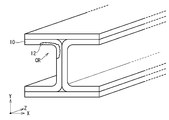
- FIG. 7 is a view showing the shape of another object to which the bonding apparatus of the embodiment can be applied.
- FIG. 8 is a side view showing a state in which a reinforcing fiber is joined to a corner of an L-shaped object and pressure molding is performed.
- FIG. 8 is a side view showing a situation in which reinforcing fibers are joined using the joining device 908 to the corners of the L-shaped object 10.
- bonding apparatus 908 is used for bonding patch 12 including reinforcing fiber 14 and matrix resin to a bonding site formed at corner portion CR in CURVE portion (bent portion) of object 10. It is an apparatus.
- the bonding device 908 includes a bag material 20, a pressure reducing port 21, a release film 22, a breather 23, a heater mat 24, and a sealant 26.
- the object 10 is a standing WEB portion (a portion extending from the bending portion to one side, and in the example shown in FIG. 8, a vertical portion) and a CAP portion (having a predetermined angle with respect to the WEB portion) A portion extending from the bending portion to the other, and in the example shown in FIG.
- the CURVE part is a part between the WEB part and the CAP part.
- the bag material 20 is a member that covers the patch 12 from the outside in a state in which the patch 12 is disposed at the bonding site at the corner of the object 10, and has airtightness.
- the bag material 20 presses the patch 12 against the object 10 using an external pressure (e.g., atmospheric pressure).
- the decompression port 21 is a port for connecting the inside of the bag material 20 and a vacuum pump (not shown).
- a vacuum pump not shown.
- the inside of the bag material 20 is decompressed.
- the external pressure presses the bag material 20 from the outside to press the patch 12 against the object 10.
- the release film 22 is a member having releasability with respect to the matrix resin and the like contained in the patch 12, and directly covers the patch 12 and the object 10.
- the breather 23 is a member for promoting the degassing inside the bag material 20.
- the breather 23 is, for example, a breathable film.
- the heater mat 24 is a device for heating the patch 12.
- the matrix resin in the patch 12 is a thermosetting resin
- the curing of the patch 12 and the adhesion to the object 10 are performed by heating.
- the heater mat 24 may include a heater that generates heat by the power from the power supply.
- the sealant 26 is a member that is disposed between the bag material 20 and the object 10 and that ensures airtightness between the outside of the bag material 20 and the inside of the bag material 20.
- cutting processing is performed on the bonding site of the object 10 as necessary to remove a damaged site.
- the patch 12 including the reinforcing fiber 14 is placed on the surface of the bonding site of the object 10. Then, the release film 22, the breather 23, the heater mat 24 and the breather 23 are sequentially disposed on the surface of the patch 12 and the object 10. Then, the sealant 26 is disposed, the pressure reducing port 21 and the vacuum pump are connected, and the inside of the bag material 20 is depressurized and degassed.
- a matrix resin is applied to the dry foam in advance, or the inside of the bag 20 is depressurized and the matrix resin is injected into the bag 20. You may Thus, the matrix resin can be impregnated into the reinforcing fibers 14.
- the heater mat 24 is energized to heat the patch 12 and the object 10.
- the inside of the bag material 20 is returned to external pressure after cooling, and the bag material 20, the release film 22, the breather 23, and the heater mat 24 are removed from the object 10.
- the finished shape (Act. Edge) of the end of the corner after joining the patch 12 is the corner part design value ( A phenomenon was observed in which the adhesive was cured in the state of coming out with respect to Nom. Edge).
- the reason why the occurrence frequency of wrinkles is high in the wrinkle generation part FW shown in FIG. 8 is that the slippage of the reinforcing fiber 14 of the patch 12 is bad in the vicinity of the wrinkle generation part FW. It is considered that, due to the poor slippage of the reinforcing fiber 14, the wrinkles generated in the reinforcing fiber 14 do not stretch and harden in a state in which slack occurs, and wrinkles are generated in the reinforcing fiber 14.
- the reinforcing fiber 14 is perpendicular to the CAP part by depressurizing the inside of the bag material 20 first (the + Y direction shown in FIG. ) Is pressed by the force of Fv (N), and a friction force ⁇ Fv (N) is generated between the reinforcing fiber 14 and the object 10.
- the frictional force ⁇ Fv makes it difficult for the reinforcing fiber 14 to slip in the X direction shown in FIG. 8, so that wrinkles remain in the wrinkle generation part FW, and wrinkles are likely to be generated.
- the force Fs for pressing in the oblique direction is based on the pressing force applied to the surface of the bag material 20 by reducing the pressure inside the bag material 20. However, it is considered that the diagonally pressing force Fs is reduced by the frictional force between the bag material 20, the release film 22, and the heater mat 24.
- the pressure in the positive X direction of the patch 12 against the reinforcing fiber 14 is insufficient at the wrinkle generating portion FW, and the wrinkles of the reinforcing fiber 14 are not stretched and are hardened, and wrinkles are easily generated.
- An experiment was conducted to bond the patch 12 under pressure. As a result of this experiment, no wrinkle was found in the reinforcing fiber 14 of the patch 12 in any of the CAP, CURVE and WEB parts.
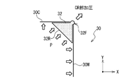
- FIG. 1 is a side view showing a state in which reinforcing fibers are joined to a corner of a target object 10 of an L-shaped material by using a joining device 8 and pressure molding is performed.
- FIG. 2 is a side view showing a configuration example including an elastic pressing body 32 (pressure block) which effectively presses the corner portion CR of the object 10 at the time of pressure molding.
- bonding apparatus 8 presses patch 12 including reinforcing fiber 14 and matrix resin to a bonding site of a corner in CURVE portion of object 10 for bonding. It is an apparatus used when doing.
- the bonding device 8 has a bag member 20, a pressure reducing port 21, a release film 22, a breather 23, a heater mat 24, a sealant 26, and a pressing member 30.
- the pressing member 30 has a first cowl plate 30 ⁇ / b> C, a second cowl plate 30 ⁇ / b> W, and an elastic pressing body 32.
- the object 10 has, for example, a WEB unit erected vertically and a CAP unit having a predetermined angle with respect to the WEB unit.
- the CURVE portion (bent portion) is a portion between the WEB portion and the CAP portion. At the corners of the CURVE portion, there are bonding sites, and the patch 12 is bonded.
- FIG. 1 shows an example in which the angle between the WEB portion and the CAP portion is at a right angle
- the angle between the WEB portion and the CAP portion is not limited to a right angle.
- the bag material 20 is a member for covering the first cowl plate 30C, the second cowl plate 30W, the elastic pressing body 32, and the patch 12 in a state where the patch 12 is disposed at the bonding site at the corner of the object 10 is there.
- the bag material 20 is airtight, and the external pressure is used to press the first cowl plate 30C, the second cowl plate 30W and the elastic pressing body 32 against the patch 12, and the patch 12 to the object 10 Press.
- the decompression port 21 is a port for connecting the inside of the bag material 20 and a vacuum pump (not shown).
- a vacuum pump not shown.
- the inside of the bag material 20 is decompressed.
- the external pressure presses the bag material 20 from the outside to press the patch 12 against the object 10.
- the release film 22 is a member having releasability with respect to the matrix resin and the like contained in the patch 12, and directly covers the patch 12 and the object 10.
- the breather 23 is a member for promoting the degassing inside the bag material 20.
- the breather 23 is, for example, a breathable film.
- a plurality of breathers 23 are arranged.
- the breather 23 is also disposed outside the first cowl plate 30C, the second cowl plate 30W, and the elastic pressing body 32.
- the heater mat 24 is a device for heating the patch 12.
- the heater mat 24 may include a heater that generates heat by the power from the power supply.
- the matrix resin in the patch 12 is a thermosetting resin
- the curing of the patch 12 and the adhesion to the object 10 are performed by heating.
- the matrix resin of the patch 12 is a thermoplastic resin
- the patch 12 is softened by heating, and the patch 12 is cured and bonded to the object 10 by cooling thereafter.
- the heater mat 24 can also be configured to perform temperature control independently for the CAP portion, the CURVE portion, and the WEB portion.
- the heater mats 24 are disposed on both sides of the object 10 on the inner side ( ⁇ X and ⁇ Y sides shown in FIG. 1) and the outer side (+ X and + Y sides shown in FIG. 1). However, depending on the heating conditions of the patch 12, the heater mat 24 can be disposed only on either the inside or the outside of the object 10.
- the sealant 26 is a member that is disposed between the bag material 20 and the object 10 and that ensures airtightness between the outside of the bag material 20 and the inside of the bag material 20.
- the first cowl plate 30C (first plate portion) is a molding repair for pressing the patch 12 joined to the corner of the object 10 toward the CAP portion of the object 10 It is a tool.
- the first cowl plate 30C extends from the corner pressing portion 32F in the -X direction (first direction).
- the first cowl plate 30C is preferably made of a material having properties (such as elasticity) that conform to the shape of the CAP portion of the object 10 to a certain extent.
- the second cowl plate 30W (second plate portion) is a shaping jig for pressing the patch 12 joined to the corner of the object 10 toward the WEB portion of the object 10.
- the second cowl plate 30W extends from the corner pressing portion 32F in the -Y direction (the second direction whose angle is different from the first direction).
- the second cowl plate 30W preferably uses a material having properties (such as elasticity) that conform to the shape of the WEB portion of the object 10 to a certain extent.
- the first cowl plate 30C and the second cowl plate 30W are arranged at different angles along the surface shapes corresponding to the corner portion design values on both sides of the corner portion CR in the object 10. And in the state shown in FIG. 2, it has a clearance gap in the position which the 1st cowl plate 30C and the 2nd cowl plate 30W approach most.
- the WEB portion and the CAP portion have a flat plate shape, but a curved surface can also be used.
- a curved surface can also be used as the first cowl plate 30C and the second cowl plate 30W.
- the elastic pressing body 32 is disposed straddling the first cowl plate 30C and the second cowl plate 30W at a portion between the first cowl plate 30C and the second cowl plate 30W.
- a portion (corner pressing portion 32F) of the elastic pressing body 32 presses the corner portion CR of the object 10 from the gap between the first cowl plate 30C and the second cowl plate 30W. It is projected to be.
- the elastic pressing body 32 has a pressure receiving surface 32R to which a pressing force is applied on the side of the bag material 20 at a portion between the first cowl plate 30C and the second cowl plate 30W.
- the elastic pressing body 32 also has a corner pressing portion 32F that protrudes in the direction of the corner portion CR of the object 10 from the gap between the first cowl plate 30C and the second cowl plate 30W.
- the elastic pressing body 32 is a shaping jig that presses the patch 12 against the bonding site at the corner portion CR of the object 10 using the corner pressing portion 32F.
- the elastic pressing body 32 diagonally presses the patch 12 toward the corner portion CR of the object 10 with a force of Fs to strengthen the force (Fs ⁇ cos ⁇ ) larger than the frictional force ⁇ Fv of the reinforcing fiber 14 It becomes easy to add in the + X direction of 14. Then, the reinforcing fiber 14 can be slid in the + X direction shown in FIG. 1 to reduce the occurrence of wrinkles around the corner portion CR.
- the elastic pressing body 32 As a material of the elastic pressing body 32, it is preferable to use a material having a property of projecting from the gap between the first cowl plate 30C and the second cowl plate 30W by the pressing force applied from the pressure receiving surface 32R. Therefore, it is preferable to use a material having physical properties with a durometer hardness of 10 or more and 55 or less for the elastic pressing body 32. Further, since it is necessary to transmit the heat of the heater mat 24 to heat the patch 12, the elastic pressing body 32 is an elastic material (silicone rubber, nitrile rubber, ethylene, etc.) having a good thermal conductivity.
- propylene rubber chloroprene rubber, styrene butadiene rubber, polybutadiene rubber, tolyl butadiene rubber, butyl rubber, urethane rubber, natural rubber, etc.
- a highly thermally conductive high thermal conductivity material for example, aluminum powder, copper powder or the like which is a high thermal conductivity powder
- the outer shape of the corner pressing portion 32F may be a shape having a predetermined curvature, or a shape based on a corner portion design value (Nom. Edge) after joining the patch 12 of the object 10 it can.
- the lengths of the portions where the elastic pressing body 32 and the first cowl plate 30C and the elastic pressing body 32 and the second cowl plate 30W are in contact are It can be 10 to 300 mm.
- the elastic pressing body 32 and the first cowl plate 30C, and the elastic pressing body 32 and the second cowl plate 30W can be bonded in advance.
- the elastic pressure body 32 and the first cowl plate 30C can be disposed without being adhered to each other, and the elastic pressure body 32 and the second cowl plate 30W can be disposed without being adhered to each other.
- the width of the gap between the first cowl plate 30C and the second cowl plate 30W, which is a portion from which the corner pressing portion 32F protrudes, can be appropriately set in accordance with the curvature of the corner portion CR.
- the first cowl plate 30C and the second cowl plate 30W may be separate and independent members, or may be configured (integrally configured) from one member having a gap for causing the elastic pressing body 32 to protrude. Even when the first cowl plate 30C and the second cowl plate 30W are formed by one member, the shapes of the WEB portion and the CAP portion of the object 10 correspond to the mutual angle between the WEB portion and the CAP portion. Preferably, the first cowl plate 30C and the second cowl plate 30W have an elasticity that follows the shape of the object 10.
- the final shape (Act. Edge) of the corner part after patch 12 junction in corner part CR part is a corner
- the outer shape is approximately equal to the part design value (Nom. Edge) (e.g. 3.2 mm) or slightly inside.
- the reinforcing fiber 14 inside the patch 12 shown in FIG. 1 no occurrence of wrinkles or slackness was observed in any of the CAP portion (including the improvement portion CB), the CURVE portion and the WEB portion.
- organic fiber such as carbon fiber, glass fiber, aramid fiber, polyparaphenylene benzobisoxazole fiber, phenol fiber, polyethylene fiber, polyvinyl alcohol fiber, metal fiber, ceramic fiber, or a combination thereof Can be used.
- thermosetting resin for example, epoxy, phenol, vinyl ester, unsaturated polyester, cyanate ester, bismaleimide, benzoxazine and other resins can be used, and in order to cure, curing agent, curing accelerator, polymerization Initiators, catalysts, etc. can be added. Further, those to which an elastomer, rubber or the like is added can also be used.
- thermoplastic resin for example, PPS (polyphenylene sulfide), PEEK (polyether ether ketone), PEKK (polyether ketone ketone), PEK (polyether ketone), PI (polyimide), PEI (polyether imide) ), PA (nylon polyamide), etc.
- PPS polyphenylene sulfide
- PEEK polyether ether ketone
- PEKK polyether ketone ketone
- PEK polyether ketone
- PI polyimide
- PEI polyether imide
- PA nylon polyamide
- the object 10 the bag member 20, the decompression port 21, the release film 22, the breather 23, the heater mat 24, the sealant 26, and the pressing member 30 are prepared (see FIG. 1).
- the bag material 20 prepares one having the pressure reducing port 21.
- the pressing member 30 prepares one having the first cowl plate 30C, the second cowl plate 30W, and the elastic pressing body 32. Further, the corner pressing portion 32F of the pressing member 30 prepares one having a surface shape corresponding to the corner portion design value (Nom. Edge) after the patch 12 is bonded.
- the patch 12 including the reinforcing fiber 14 is placed in contact with the bonding site of the corner portion CR of the object 10. Then, the release film 22 is disposed on the patch 12, and the pressing member 30, the breather 23, the heater mat 24, and the like are appropriately disposed.
- the sealant 26 is disposed, and the bonding site of the object 10, the patch 12, the release film 22, the pressing member 30, the breather 23, and the heater mat 24 are covered with the bag material 20 using the bag material 20.
- a sealed space is formed including ten bonding sites.
- Step of pressing the corner CR When a pressing force is applied to the pressure receiving surface 32R of the elastic pressing body 32, the corner pressing portion 32F of the elastic pressing body 32 is a target from the gap between the first cowl plate 30C and the second cowl plate 30W. It projects in the direction of the corner portion CR of the object 10. Then, the corner pressing portion 32F presses the patch 12 toward the bonding site of the corner portion CR of the object 10. Then, since the reinforcing fibers 14 contained in the patch 12 are pulled toward the corner portion CR, the occurrence of wrinkles in the improvement portion CB around the corner portion CR can be reduced.
- the heater mat 24 is energized for a predetermined time to heat the object 10 and the patch 12.
- a thermosetting resin is used as the matrix resin of the patch 12, it is cured at the time of heating to bond the object 10 and the patch 12 and perform molding.
- a thermoplastic resin is used as the matrix resin of the patch 12, it is cured at the cooling after heating, and the object 10 and the patch 12 are joined and molded.
- Step of removing the bag material 20 When the molding is completed, the bag material 20, the sealant 26, the release film 22, the pressing member 30, the breather 23, and the heater mat 24 are removed. Thus, bonding of the patch 12 to the object 10 is performed.
- FIG. 3 is a side view showing a state in which reinforcing fibers are joined to a corner of the object 10 of the L-shaped material by using the joining device 18 and pressure molding is performed.
- part which has the function same as the site
- bonding device 18 is a device used when bonding patch 12 including reinforcing fiber 14 and a matrix resin to a bonding site generated at a corner of CURVE portion of object 10.
- the bonding device 18 includes a bag member 20, a decompression port 21, a release film 22, a breather 23, a heater mat 24, a sealant 26, and a pressing member 30P.
- the pressing member 30P includes a first plate portion extending from the pressing portion 30F along the CAP portion in the ⁇ X direction (first direction), and a second direction (different from the first direction from the pressing portion 30F) And a second plate portion extending along the WEB portion toward the (Y direction).
- the first plate portion of the pressing member 30P biases the patch 12 toward the CAP portion of the object 10.
- the pressing portion 30F of the pressing member 30P urges the patch 12 toward the bonding site at the corner portion CR of the object 10.
- the second plate portion of the pressing member 30P urges the patch 12 toward the WEB portion of the object 10. It is preferable to use a material having properties (such as elasticity) conforming to the shape of the object 10 for the pressing member 30P.
- biasing device 40 biases the pressing member 30P toward the joining site of the patch 12 and the object 10.
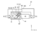
- FIG. 4 is a side view illustrating an embodiment in which the pressing unit 42T presses the patch 12 against the bonding site using the clamp force FC generated by the biasing device 40.
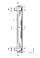
- FIG. 5 is a front view of the biasing device 40 shown in FIG. 4 as viewed from the -X direction.
- FIG. 6 is a cross-sectional view of the biasing device 40 shown in FIG.
- the biasing device 40 has a first biasing force applying portion 40I, a second biasing force applying portion 40E, and a biasing force applying member 42.
- the tip of the biasing force applying member 42 has a pressing portion 42T.
- the biasing device 40 also includes a tilt block 44, a slide block 43 and a back block 46.
- the first biasing force application unit 40I and the second biasing force application unit 40E apply a clamping force FC for sandwiching the biasing force application member 42 and the object 10 via the slide block 43 and the back block 46.
- the inclined block 44 shown in FIG. 4 is a triangular prism having a right triangle cross section.
- the right triangle also includes a substantially right triangle.
- the plane along the X-axis of the inclined block 44 and the plane along the Y-axis are two planes orthogonal to each other. The two surfaces are in contact with the side to be joined of the object 10.
- the inclined surface (the surface inclined with respect to the X axis and the Y axis) of the inclined block 44 has the slide block 43 and the biasing force applying member 42 in the third direction (the direction in which the pressing portion 42T is biased toward the corner portion CR) It is a sliding slope BV which is made to slide.
- the slide block 43 receives the clamp force FC in the + X direction, and slides in the corner portion CR direction (third direction) along the sliding slope BV of the inclined block 44. As a result, the clamping force FC is converted to a pressure force FD. The pressure FD is transmitted to the biasing member 42.
- the biasing force application member 42 receives the pressure force FD from the inclined block 44, slides in the direction of the corner portion CR and extends, and the pressing portion 42T applies the patch 12 to the object 10 via the bag material 20 and the like. Press (see FIG. 3).
- the component force in the direction in which the first plate portion of the pressing member 30P is urged toward the patch 12 and the second plate in the pressing member 30P can be used for the component force in the inclination direction (third direction) of the sliding slope BV. And a component in the direction of biasing the part towards the patch 12.
- the back block 46 is disposed on the back side of the target 10 with respect to the bonding site.
- the back block 46 receives the clamping force FC in the -X direction from the second biasing force application unit 40E, and transmits the clamping force FC to the object 10.
- the clamping force FC generated by the first biasing force application unit 40I and the second biasing force application unit 40E is converted into a pressing force FD, and biases the patch 12 toward the bonding site of the object 10. And pressure molding can be performed.
- FIG. 5 is a view for explaining the arrangement of the object 10 and the biasing force applying member 42 in the central portion of the object 10.
- the object 10 the bag member 20, the decompression port 21, the release film 22, the breather 23, the heater mat 24, the sealant 26, the pressing member 30P, and the biasing device 40 are prepared (see FIG. 3 to 7).
- the bag material 20 may be prepared to have a decompression port 21.
- the shape including the pressing part 30F of the pressing member 30P prepares one having a surface shape corresponding to the design value (Nom. Edge) of the corner after the object 10 and the patch 12 are joined.
- the patch 12 including the reinforcing fiber 14 is placed in contact with the bonding site of the corner portion CR of the object 10. Then, the release film 22 is disposed on the patch 12, and the pressing member 30P, the breather 23, the heater mat 24, and the like are appropriately disposed.
- the sealant 26 is disposed, and the bonding site of the object 10, the patch 12, the release film 22, the pressing member 30P, the breather 23, and the heater mat 24 are covered with the bag material 20 using the bag material 20.
- a sealed space is formed including ten bonding sites.
- Step of pressing the corner CR Next, as shown in FIGS. 4 to 6, outside the sealed space formed by the bag material and the object 10, the inclined block 44 and the biasing force application member 42 are disposed with respect to the object 10. At this time, the pressurizing unit 42T is arranged to press the patch 12 toward the corner portion CR of the object 10. Then, the slide block 43 and the back block 46 are disposed. Next, the first urging force application unit 40I and the second urging force application unit 40E are disposed. Then, the clamp force FC is applied to the slide block 43 and the back block 46. Then, the biasing force applying member 42 moves along the sliding slope BV, and the pressing unit 42T presses the patch 12 toward the corner portion CR of the object 10. Then, since the reinforcing fibers 14 contained in the patch 12 are pulled toward the corner portion CR, the occurrence of wrinkles around the corner portion CR can be reduced.
- Heating process The heater mat 24 is energized for a predetermined time to heat the object 10 and the patch 13.
- Step of removing the bag material 20 When the molding is completed, the biasing device 40, the bag material 20, the sealant 26, the release film 22, the pressing member 30P, the breather 23, and the heater mat 24 are removed. Thus, the bonding of the patch 12 to the object 10 is completed.
- FIG. 7 shows an application example to another object. Bonding of the patch 12 to the object 10 using the bonding apparatus according to the present invention is achieved by bonding the L-shaped members shown in FIG. 1 and FIG. 3 and the like and the U-shaped cross-sectional members shown in FIGS.
- the present invention is not limited to the above, and can be applied to the repair or manufacture of the bonding site at the corner portion CR of the H-shaped material shown in FIG.
- the embodiment in which the patch 12 for repair is joined to the object 10 has been described.
- the embodiments may be used to apply a patch to an object having a bonding site to manufacture various members or devices.
- the joining apparatus, the kit, the pressing member, the biasing apparatus and the joining method according to the present invention have been described above with reference to the embodiment, but the joining apparatus, the kit, the pressing member, the biasing apparatus and the joining method according to the present invention It is not limited to the embodiment.
- Various modifications can be made to the above embodiments. It is possible to combine the matters described in the above embodiment with the matters described in the other embodiments.
- the present invention can be applied to a resin transfer molding (RTM) method, a vacuum-assisted resin transfer molding (VaRTM) method, a double vacuum debulking method, an autoclave method, and other molding methods.
- the pressing member is a member for pressing the patch including the reinforcing fiber to the bonding site in the corner portion of the object
- the pressing member includes the first plate portion and the second plate portion And an elastic pressing body.
- the first plate portion and the second plate portion are disposed at different angles along the shapes on both sides of the corner portion of the object, and the corner portion is disposed between the first plate portion and the second plate portion.
- a gap is provided at a position corresponding to the part.
- the elastic pressing body is disposed across the first plate portion and the second plate portion, between the first plate portion and the second plate portion.
- a pressure receiving surface to which a pressing force is applied is provided between the first plate portion and the second plate portion opposite to the gap.
- the biasing device is a device that presses a patch including reinforcing fibers to a bonding site at a corner portion of an object.
- the biasing device includes a first biasing force applying portion, a second biasing force applying portion, and a biasing force applying member.
- the biasing force applying member has a pressing portion at its tip.
- the first biasing force application unit and the second biasing force application unit apply a clamping force for sandwiching the biasing force application member and the object.
- the pressing portion presses the patch against the bonding site.
- the biasing device may further include a tilt block, a slide block and a back block.
- the inclined block, the slide block, and the biasing force applying member are disposed on the side to be joined in the object, and the back block is disposed on the back side on the side of the region to be joined on the object.
- the tilt block has a slide slope for sliding the slide block and the biasing member in the third direction. By sliding along the sliding slope, the slide block converts a clamping force in a direction different from the third direction into a pressing force in the third direction and transmits it to the biasing force applying member.
- the pressing portion presses the patch against the bonding site by sliding along the sliding slope.
Abstract
Description
図1を参照して、本発明の第1実施形態に係る接合装置8は、対象物10のCURVE部におけるコーナーの被接合部位に、強化繊維14及びマトリックス樹脂を含むパッチ12を押圧して接合する際に用いる装置である。接合装置8は、バッグ材20と、減圧ポート21と、離型フィルム22と、ブリーザー23と、ヒーターマット24と、シーラント26と、押圧部材30とを有する。図2を参照して、押圧部材30は、第1カウルプレート30Cと、第2カウルプレート30Wと、弾性加圧体32とを有する。 First Embodiment
Referring to FIG. 1,
コーナー部CRに被接合部位を有する対象物10に対して、接合装置8を用いて強化繊維14を含むパッチ12を接合する方法について説明する。 (Description of the bonding method for bonding the
A method of joining the
先ず、対象物10と、バッグ材20と、減圧ポート21と、離型フィルム22と、ブリーザー23と、ヒーターマット24と、シーラント26と、押圧部材30とを準備する(図1参照)。バッグ材20は、減圧ポート21を有するものを準備する。押圧部材30は、第1カウルプレート30Cと、第2カウルプレート30Wと、弾性加圧体32とを有するものを準備する。また、押圧部材30のコーナー加圧部32Fは、パッチ12接合後のコーナー部設計値(Nom.edge)に対応する表面形状を有するものを準備する。 (Preparation process)
First, the
次に、必要に応じて、対象物10のコーナーの被接合部位に対して切除加工を行って、損傷した部位、又は不要な部位を切除する下処理を行う。 (Lower treatment process)
Next, if necessary, a cutting process is performed on the bonding site of the corner of the
次に、対象物10のコーナー部CRの被接合部位に、強化繊維14を含むパッチ12が接触するように配置する。そして、パッチ12の上に離型フィルム22を配置し、押圧部材30、ブリーザー23、ヒーターマット24等を適宜配置する。 (Placement process)
Next, the
シーラント26を配置して、バッグ材20を用いて対象物10の被接合部位、パッチ12、離型フィルム22、押圧部材30、ブリーザー23、及びヒーターマット24を、バッグ材20で覆い、対象物10の被接合部位を含む密閉空間を形成する。 (Sealed space formation process)
The
被接合部位を囲む密閉空間が形成されたら、減圧ポート21に真空ポンプを接続して、密閉空間内の気体を吸引脱気する。すると、外圧によって第1カウルプレート30Cは、パッチ12を対象物10のCAP部に向けて押圧する。同様に第2カウルプレート30Wは、パッチ12を対象物10のWEB部に向けて押圧して成形する。そして、弾性加圧体32の受圧面32Rには、押圧力が付与される。 (Degassing process)
After the sealed space surrounding the bonding site is formed, a vacuum pump is connected to the
弾性加圧体32の受圧面32Rに押圧力が付与されると、弾性加圧体32のコーナー加圧部32Fは、第1カウルプレート30Cと第2カウルプレート30Wとの間の隙間から、対象物10のコーナー部CRの方向に突出する。すると、コーナー加圧部32Fは、パッチ12を対象物10のコーナー部CRの被接合部位に向けて押圧する。そして、パッチ12に含まれる強化繊維14がコーナー部CRに向けて引っ張られるので、コーナー部CRの周辺の改善部CBにおけるリンクルの発生を減少させることができる。 (Step of pressing the corner CR)
When a pressing force is applied to the
所定の時間の間、ヒーターマット24に通電を行って、対象物10とパッチ12とを加熱する。パッチ12のマトリックス樹脂に熱硬化性樹脂を用いる場合には、加熱時に硬化して対象物10とパッチ12とを接合するとともに、成形を行う。パッチ12のマトリックス樹脂に熱可塑性樹脂を用いる場合には、加熱後の冷却時に硬化して、対象物10とパッチ12とを接合するとともに成形を行う。 (Heating process)
The
成形が終了したら、バッグ材20、シーラント26、離型フィルム22、押圧部材30、ブリーザー23、及びヒーターマット24を取り除く。このようにして、対象物10に対するパッチ12の接合を行う。 (Step of removing the bag material 20)
When the molding is completed, the
第1実施形態では、対象物10のコーナー部CRを、弾性加圧体32を用いて押圧する実施形態について説明した。これに対し、第2の実施形態では、対象物10のコーナー部CRを、押圧部材30Pの角部に形成されている加圧部30Fを用いて押圧する実施形態について説明する。 Second Embodiment
In the first embodiment, the embodiment in which the corner portion CR of the
図3に示すように、押圧部材30Pの角部には加圧部30Fが形成されている。押圧部材30Pは、加圧部30Fから-X方向(第1方向)に向けてCAP部に沿って延出する第1板部と、加圧部30Fから第1方向とは異なる第2方向(-Y方向)に向けてWEB部に沿って延出する第2板部とを有する。 (Description of the
As shown in FIG. 3, a
次に、図4乃至図6を用いて、図3に示した押圧部材30Pを、バッグ材20の外圧に加えて更に付勢装置40を用いて加圧成形を行う実施形態について説明する。付勢装置40は、押圧部材30Pを、パッチ12及び対象物10の被接合部位に向けて付勢する。 (Description of biasing device 40)
Next, an embodiment in which the
次に、コーナー部CRに被接合部位を有する対象物10に対して、接合装置18及び付勢装置40を用いて強化繊維14を含むパッチ12を接合する方法について説明する。 (Description of the bonding method for bonding the
Next, a method of joining the
先ず、対象物10と、バッグ材20と、減圧ポート21と、離型フィルム22と、ブリーザー23と、ヒーターマット24と、シーラント26と、押圧部材30Pと、付勢装置40とを準備する(図3乃至図7参照)。バッグ材20は、減圧ポート21を有するものを準備すると良い。押圧部材30Pの加圧部30Fを含む形状は、対象物10及びパッチ12接合後のコーナー部設計値(Nom.edge)に対応する表面形状を有するものを準備する。 (Preparation process)
First, the
次に、必要に応じて対象物10のコーナーの被接合部位に対して切除加工を行って、損傷した部位、又は不要な部位を切除する下処理を行う。 (Lower treatment process)
Next, a cutting process is performed on the bonding site of the corner of the
次に、図3に示すように、対象物10のコーナー部CRの被接合部位に、強化繊維14を含むパッチ12が接触するように配置する。そして、パッチ12の上に離型フィルム22を配置し、押圧部材30P、ブリーザー23、ヒーターマット24等を適宜配置する。 (Placement process)
Next, as shown in FIG. 3, the
シーラント26を配置して、バッグ材20を用いて対象物10の被接合部位、パッチ12、離型フィルム22、押圧部材30P、ブリーザー23、及びヒーターマット24を、バッグ材20で覆い、対象物10の被接合部位を含む密閉空間を形成する。 (Sealed space formation process)
The
被接合部位を囲む密閉空間が形成されたら、減圧ポート21に真空ポンプを接続して、密閉空間内の気体を吸引脱気する。すると、外圧によって押圧部材30Pは、パッチ12を対象物10のCAP部、WEB部に向けて押圧して成形する。 (Degassing process)
After the sealed space surrounding the bonding site is formed, a vacuum pump is connected to the
次に、図4乃至図6に示すように、バッグ材と対象物10とにより形成される密閉空間の外部に、対象物10に対して傾斜ブロック44及び付勢力付与部材42を配置する。このとき、加圧部42Tがパッチ12を、対象物10のコーナー部CRに向けて加圧するように配置する。そして、スライドブロック43及びバックブロック46を配置する。次に、第1付勢力付与部40I及び第2付勢力付与部40Eを配置する。そして、スライドブロック43及びバックブロック46に対してクランプ力FCを印加する。すると、付勢力付与部材42が摺動斜面BVに沿って移動し、加圧部42Tがパッチ12を対象物10のコーナー部CRに向けて押圧する。すると、パッチ12に含まれる強化繊維14がコーナー部CRに向けて引っ張られるので、コーナー部CRの周辺におけるリンクルの発生を減少させることができる。 (Step of pressing the corner CR)
Next, as shown in FIGS. 4 to 6, outside the sealed space formed by the bag material and the
所定の時間の間、ヒーターマット24に通電を行って、対象物10とパッチ13とを加熱する。 (Heating process)
The
成形が終了したら、付勢装置40、バッグ材20、シーラント26、離型フィルム22、押圧部材30P、ブリーザー23、及びヒーターマット24を取り除く。こうして、対象物10に対するパッチ12の接合が終了する。 (Step of removing the bag material 20)
When the molding is completed, the biasing
図7に、他の対象物への適用例を示す。本発明による接合装置を用いた対象物10に対するパッチ12の接合は、図1及び図3等に示したL形型材、及び図4乃至図6に示したコの字断面の型材における被接合部位に限らず、図7に示すH形型材のコーナー部CRにおける被接合部位の補修や製造に適用することができる。なお、上記の実施形態では、被対象物10に補修用のパッチ12を接合する実施形態について説明した。しかし、実施形態は、被接合部位を有する対象物にパッチを適用して、各種の部材又は装置を製造するために用いられてもよい。 (Example of application to other objects)
FIG. 7 shows an application example to another object. Bonding of the
Claims (11)
- 対象物のコーナー部の表面部分の被接合部位に、強化繊維を含むパッチを接合する接合装置であって、
印加される力に応答して前記接合されたパッチの表面を押圧する押圧部材と、
前記押圧部材に前記印加力を付与する付勢部と
を具備する
接合装置。 A bonding apparatus for bonding a patch including reinforcing fibers to a bonding site of a surface portion of a corner portion of an object,
A pressing member for pressing the surface of the joined patch in response to an applied force;
And a biasing unit that applies the application force to the pressing member. - 請求項1に記載の接合装置において、
前記押圧部材は、
前記コーナー部から前記対象物に沿って第1方向に延びる第1板部と、
前記コーナー部から前記対象物に沿って、前記第1方向とは異なる第2方向に延びる第2板部と
を備え、
前記印加力に応答して前記第1板部と前記第2板部とで前記対象物を押圧する
接合装置。 In the welding device according to claim 1,
The pressing member is
A first plate portion extending in a first direction along the object from the corner portion;
And a second plate portion extending in a second direction different from the first direction along the object from the corner portion,
A bonding apparatus which presses the object with the first plate portion and the second plate portion in response to the applied force. - 請求項1に記載の接合装置において、
前記押圧部材は、
前記コーナー部から前記対象物に沿って第1方向に延びる第1板部と、
前記コーナー部から前記対象物に沿って、前記第1方向とは異なる第2方向に延びる第2板部と、
前記第1板部と前記第2板部との間を通って前記コーナー部を押圧する弾性加圧体と
を備え、
前記弾性加圧体は、前記印加力が付与される受圧面と、前記印加力に応答して前記第1板部と前記第2板部との間の隙間を通って前記コーナー部を押圧する加圧部とを有する
接合装置。 In the welding device according to claim 1,
The pressing member is
A first plate portion extending in a first direction along the object from the corner portion;
A second plate portion extending in a second direction different from the first direction along the object from the corner portion;
And an elastic pressing body that presses the corner portion between the first plate portion and the second plate portion.
The elastic pressing body presses the corner portion through a gap between the first plate portion and the second plate portion in response to the pressure receiving surface to which the application force is applied, and the application force. Bonding device having a pressure part. - 請求項3に記載の接合装置において、
前記弾性加圧体は、デュロメータ硬度が10以上55以下である
接合装置。 In the welding device according to claim 3,
The elastic pressure body has a durometer hardness of 10 or more and 55 or less. - 請求項3又は4に記載の接合装置において、
前記弾性加圧体には、高熱伝導材料が添加されている
接合装置。 In the bonding apparatus according to claim 3 or 4,
A high thermal conductivity material is added to the elastic pressing body. - 請求項1乃至5のいずれか一項に記載の接合装置において、
前記パッチを加熱する加熱装置と、
前記対象物における前記被接合部位を含む前記表面部分、前記パッチ、前記加熱装置、および前記押圧部材を被うバッグ材と
を更に具備し、
前記バッグ材の内部は減圧され、前記印加力は、その内部が減圧された前記バッグ材を介して前記押圧部材を前記コーナー部に向かう方向に付勢する大気圧である
接合装置。 The bonding apparatus according to any one of claims 1 to 5.
A heating device for heating the patch;
The surface portion including the bonding site on the object, the patch, the heating device, and a bag material covering the pressing member.
The inside of the bag material is depressurized, and the applied force is an atmospheric pressure that biases the pressing member in the direction toward the corner portion via the bag material whose inside is depressurized. - 請求項1に記載の接合装置において、
前記パッチを加熱する加熱装置と、
前記対象物における前記被接合部位を含む前記表面部分、前記パッチ、前記加熱装置、および前記押圧部材を被うバッグ材と
を更に具備し、
前記バッグ材の内部は減圧され、
前記付勢部は、前記バッグ材と前記対象物とにより形成される密閉空間の外部に配置され、前記押圧部材を前記パッチに向けて付勢する
接合装置。 In the welding device according to claim 1,
A heating device for heating the patch;
The surface portion including the bonding site on the object, the patch, the heating device, and a bag material covering the pressing member.
The inside of the bag material is depressurized,
The bonding unit is disposed outside a sealed space formed by the bag material and the object, and biases the pressing member toward the patch. - 請求項7に記載の接合装置において、
前記付勢部は、前記コーナー部と、前記コーナー部から延びる前記対象物の部分とに前記印加力を付与する付与部材を有する
接合装置。 In the welding device according to claim 7,
The said urging | biasing part has an application member which applies the said applied force to the said corner part and the part of the said target object extended from the said corner part. Joining apparatus. - 請求項8に記載の接合装置において、
前記付勢部は、傾斜ブロックとスライドブロックとを更に備え、
前記傾斜ブロックは、前記スライドブロックおよび前記付与部材がその摺動斜面に沿って摺動する摺動斜面を有し、
前記スライドブロックは、前記摺動斜面に沿って摺動することにより、前記コーナー部の方向とは異なる方向のクランプ力を、前記コーナー部の方向の前記印加力に変換して前記付与部材に伝達する
接合装置。 In the welding device according to claim 8,
The biasing unit further includes a tilt block and a slide block,
The inclined block has a sliding slope on which the slide block and the application member slide along the sliding slope.
The slide block slides along the sliding slope to convert a clamping force in a direction different from the direction of the corner portion into the applied force in the direction of the corner portion and transmits the applied force to the application member. Bonding device. - 請求項9に記載の接合装置において、
前記傾斜ブロック、前記スライドブロックおよび前記付与部材は、前記対象物における前記被接合部位側に配置され、
前記付勢部は、前記対象物における前記被接合部位側の裏面側に、前記クランプ力を印加するバックブロックを更に有する
接合装置。 In the welding device according to claim 9,
The inclined block, the slide block, and the application member are disposed on the side to be joined of the object,
The said urging | biasing part further has the back block which applies the said clamp force in the back surface side by the side of the said to-be-joined site | part in the said target object. Bonding device. - 対象物のコーナー部の表面部分の被接合部位に、強化繊維を含むパッチを接合する接合方法であって、
減圧ポートを有するバッグ材と、加熱装置と、パッチの表面を押圧する押圧部材とを準備する工程と、
対象物のコーナー部の表面部分の被接合部位に、強化繊維を含むパッチを配置する工程と、
前記コーナー部の前記被接合部位に向けて前記押圧部材を配置する工程と、
バッグ材と前記対象物とにより密閉空間を形成する工程と、前記密閉空間には、前記パッチ、パッチを加熱するための加熱装置、および前記押圧部材が含まれ、
前記密閉空間の内部を減圧する工程と、
前記バッグ材を介して前記押圧部材を、前記コーナー部に向けて押圧する工程と、
前記加熱装置によって、前記対象物と前記パッチとを加熱して接合する工程と
を具備する
接合方法。 A bonding method for bonding a patch including reinforcing fibers to a bonding site of a surface portion of a corner portion of an object,
Preparing a bag material having a pressure reducing port, a heating device, and a pressing member for pressing the surface of the patch;
Placing a patch containing reinforcing fibers at the bonding site of the surface portion of the corner portion of the object;
Disposing the pressing member toward the bonding site of the corner portion;
Forming a sealed space by the bag material and the object; and the sealed space includes the patch, a heating device for heating the patch, and the pressing member.
Decompressing the inside of the enclosed space;
Pressing the pressing member toward the corner portion via the bag material;
Heating and joining the object and the patch by the heating device.
Priority Applications (5)
| Application Number | Priority Date | Filing Date | Title |
|---|---|---|---|
| CN201580041094.XA CN106573422B (en) | 2014-11-25 | 2015-11-25 | Joining device and joining method |
| BR112017003982A BR112017003982A2 (en) | 2014-11-25 | 2015-11-25 | binding apparatus, and binding method for binding a patch containing a reinforcing fiber to a bonded section of a surface portion. |
| EP15863240.6A EP3181339B1 (en) | 2014-11-25 | 2015-11-25 | Bonding device and bonding method |
| CA2959476A CA2959476C (en) | 2014-11-25 | 2015-11-25 | Bonding apparatus and bonding method |
| US15/507,757 US10456961B2 (en) | 2014-11-25 | 2015-11-25 | Bonding apparatus and bonding method |
Applications Claiming Priority (2)
| Application Number | Priority Date | Filing Date | Title |
|---|---|---|---|
| JP2014-238073 | 2014-11-25 | ||
| JP2014238073A JP6463094B2 (en) | 2014-11-25 | 2014-11-25 | Joining apparatus and joining method |
Publications (1)
| Publication Number | Publication Date |
|---|---|
| WO2016084861A1 true WO2016084861A1 (en) | 2016-06-02 |
Family
ID=56074413
Family Applications (1)
| Application Number | Title | Priority Date | Filing Date |
|---|---|---|---|
| PCT/JP2015/083112 WO2016084861A1 (en) | 2014-11-25 | 2015-11-25 | Bonding device and bonding method |
Country Status (7)
| Country | Link |
|---|---|
| US (1) | US10456961B2 (en) |
| EP (1) | EP3181339B1 (en) |
| JP (1) | JP6463094B2 (en) |
| CN (1) | CN106573422B (en) |
| BR (1) | BR112017003982A2 (en) |
| CA (1) | CA2959476C (en) |
| WO (1) | WO2016084861A1 (en) |
Cited By (5)
| Publication number | Priority date | Publication date | Assignee | Title |
|---|---|---|---|---|
| DE102017004339A1 (en) * | 2017-05-05 | 2018-11-08 | Audi Ag | Method for producing a fiber composite component, fiber composite component for a motor vehicle, motor vehicle with a fiber composite component and apparatus for producing a fiber composite component |
| US20180361690A1 (en) * | 2017-06-15 | 2018-12-20 | GM Global Technology Operations LLC | Heating elements for repair of molding defects for carbon fiber thermoplastic composites |
| US10589477B2 (en) | 2016-05-02 | 2020-03-17 | GM Global Technology Operations LLC | Cosmetic repair of a thermoplastic carbon fiber composite |
| US10695993B2 (en) | 2016-01-15 | 2020-06-30 | GM Global Technology Operations LLC | In-situ polymerization of polyamides for composite part repair |
| JP2020189409A (en) * | 2019-05-20 | 2020-11-26 | 日産自動車株式会社 | Fiber reinforced resin panel and molding method thereof |
Families Citing this family (3)
| Publication number | Priority date | Publication date | Assignee | Title |
|---|---|---|---|---|
| US11046017B2 (en) * | 2016-11-07 | 2021-06-29 | Robert Bosch Battery Systems Llc | Device and method for forming complex joints in layered sheet material |
| US20230100087A1 (en) * | 2020-06-17 | 2023-03-30 | Mitsubishi Heavy Industries, Ltd. | Jig and composite material processing method |
| KR102315158B1 (en) * | 2021-05-12 | 2021-10-20 | 오시찬 | Device for adhesive emission |
Citations (2)
| Publication number | Priority date | Publication date | Assignee | Title |
|---|---|---|---|---|
| JP2011507738A (en) * | 2007-12-28 | 2011-03-10 | エアバス オペラツィオンス ゲゼルシャフト ミット ベシュレンクテル ハフツング | Method for producing a profile from a fiber composite material |
| JP2013513499A (en) * | 2009-12-14 | 2013-04-22 | ザ・ボーイング・カンパニー | High temperature composite tool |
Family Cites Families (11)
| Publication number | Priority date | Publication date | Assignee | Title |
|---|---|---|---|---|
| FR2638673B1 (en) * | 1988-11-08 | 1991-03-22 | Aerospatiale | TOOLS FOR MOLDING SELF-RAIDED PANELS OF COMPOSITE MATERIAL |
| GB9622780D0 (en) * | 1996-11-01 | 1997-01-08 | British Aerospace | Repair of composite laminates |
| US6761783B2 (en) * | 2002-04-09 | 2004-07-13 | The Boeing Company | Process method to repair bismaleimide (BMI) composite structures |
| DE602005026946D1 (en) * | 2004-07-16 | 2011-04-28 | Mitsubishi Chem Corp | ELECTRO-PHOTOGRAPHIC LIGHT-SENSITIVE BODY |
| US8790485B2 (en) | 2005-02-25 | 2014-07-29 | Bell Helicopter Textron Inc. | Single vacuum debulk composite panel repair |
| US7857925B2 (en) | 2007-06-15 | 2010-12-28 | The Boeing Company | Process development protocol and vacuum bag process for carbon-epoxy prepreg |
| US8382924B2 (en) | 2007-11-26 | 2013-02-26 | Textron Innovations Inc. | Multi-stage debulk and compaction of thick composite repair laminates |
| JP4929147B2 (en) | 2007-12-19 | 2012-05-09 | 三菱重工業株式会社 | How to repair resin products |
| DE102009001075A1 (en) * | 2009-02-23 | 2010-09-09 | Airbus Deutschland Gmbh | Method for at least partially reworking or replacing a stiffening element of a fiber composite structure and associated attachment device |
| IT1399682B1 (en) * | 2010-03-29 | 2013-04-26 | Alenia Aeronautica Spa | PROCEDURE AND DEVICE FOR THE REPAIR OF COMPOSITE MATERIAL PANELS |
| US8986479B2 (en) | 2010-09-30 | 2015-03-24 | The Boeing Company | Systems and methods for on-aircraft composite repair using double vacuum debulking |
-
2014
- 2014-11-25 JP JP2014238073A patent/JP6463094B2/en active Active
-
2015
- 2015-11-25 EP EP15863240.6A patent/EP3181339B1/en active Active
- 2015-11-25 BR BR112017003982A patent/BR112017003982A2/en active Search and Examination
- 2015-11-25 US US15/507,757 patent/US10456961B2/en active Active
- 2015-11-25 CA CA2959476A patent/CA2959476C/en active Active
- 2015-11-25 WO PCT/JP2015/083112 patent/WO2016084861A1/en active Application Filing
- 2015-11-25 CN CN201580041094.XA patent/CN106573422B/en not_active Expired - Fee Related
Patent Citations (2)
| Publication number | Priority date | Publication date | Assignee | Title |
|---|---|---|---|---|
| JP2011507738A (en) * | 2007-12-28 | 2011-03-10 | エアバス オペラツィオンス ゲゼルシャフト ミット ベシュレンクテル ハフツング | Method for producing a profile from a fiber composite material |
| JP2013513499A (en) * | 2009-12-14 | 2013-04-22 | ザ・ボーイング・カンパニー | High temperature composite tool |
Cited By (10)
| Publication number | Priority date | Publication date | Assignee | Title |
|---|---|---|---|---|
| US10695993B2 (en) | 2016-01-15 | 2020-06-30 | GM Global Technology Operations LLC | In-situ polymerization of polyamides for composite part repair |
| US10589477B2 (en) | 2016-05-02 | 2020-03-17 | GM Global Technology Operations LLC | Cosmetic repair of a thermoplastic carbon fiber composite |
| DE102017004339A1 (en) * | 2017-05-05 | 2018-11-08 | Audi Ag | Method for producing a fiber composite component, fiber composite component for a motor vehicle, motor vehicle with a fiber composite component and apparatus for producing a fiber composite component |
| DE102017004339B4 (en) * | 2017-05-05 | 2021-05-12 | Audi Ag | Method for producing a fiber composite component |
| US20180361690A1 (en) * | 2017-06-15 | 2018-12-20 | GM Global Technology Operations LLC | Heating elements for repair of molding defects for carbon fiber thermoplastic composites |
| CN109109348A (en) * | 2017-06-15 | 2019-01-01 | 通用汽车环球科技运作有限责任公司 | For repairing the heating element of composite thermoplastic carbon fiber material moulding faults |
| US10611104B2 (en) * | 2017-06-15 | 2020-04-07 | GM Global Technology Operations LLC | Heating elements for repair of molding defects for carbon fiber thermoplastic composites |
| CN109109348B (en) * | 2017-06-15 | 2021-06-08 | 通用汽车环球科技运作有限责任公司 | Heating element for repairing molding defects of carbon fiber thermoplastic composite material |
| JP2020189409A (en) * | 2019-05-20 | 2020-11-26 | 日産自動車株式会社 | Fiber reinforced resin panel and molding method thereof |
| JP7291536B2 (en) | 2019-05-20 | 2023-06-15 | 日産自動車株式会社 | Fiber-reinforced resin panel and molding method thereof |
Also Published As
| Publication number | Publication date |
|---|---|
| BR112017003982A2 (en) | 2017-12-12 |
| CA2959476A1 (en) | 2016-06-02 |
| CN106573422B (en) | 2020-05-12 |
| CA2959476C (en) | 2019-09-17 |
| JP2016097633A (en) | 2016-05-30 |
| EP3181339B1 (en) | 2021-02-24 |
| EP3181339A4 (en) | 2017-09-06 |
| JP6463094B2 (en) | 2019-01-30 |
| US10456961B2 (en) | 2019-10-29 |
| US20170305044A1 (en) | 2017-10-26 |
| EP3181339A1 (en) | 2017-06-21 |
| CN106573422A (en) | 2017-04-19 |
Similar Documents
| Publication | Publication Date | Title |
|---|---|---|
| WO2016084861A1 (en) | Bonding device and bonding method | |
| US8734711B2 (en) | Method for producing a profile from composite fiber material | |
| KR102069926B1 (en) | Composite structure having a stabilizing element | |
| JP5891244B2 (en) | Method and apparatus for compressing a composite radius | |
| JP6325545B2 (en) | Apparatus for manufacturing a flanged component and its manufacturing method | |
| JP2007118598A (en) | Method and apparatus for manufacturing preform | |
| JP6785866B2 (en) | Composite material molding method and composite material molding jig | |
| JP2013022834A (en) | Composite material of fiber-reinforced resin and lightweight core, and method and apparatus for producing the same | |
| US20160346965A1 (en) | Method and tool for forming a scarf joint | |
| JP2010137527A (en) | Repairing method for composite material | |
| JP2014188999A (en) | Molding device for fiber-reinforced plastic member, and method for molding the same | |
| CN110901104B (en) | Preform shaping method and composite material shaping method | |
| JP6667055B2 (en) | Mold for producing composite material molded article and method for producing composite material molded article | |
| EP2662203B1 (en) | Contour caul with expansion region and method for its manufacture | |
| JP5587916B2 (en) | Manufacturing method of composite parts | |
| ATE506175T1 (en) | GLUED PRINTING PLATE AND METHOD FOR PRODUCING THE SAME | |
| EP3392027B1 (en) | Systems and methods for assembling elongate composite structures | |
| CN110104202B (en) | Composite aircraft manufacturing tool using articulated mandrels | |
| JP2020032581A (en) | Preform shaping method and composite material molding method | |
| WO2024048094A1 (en) | Molding method and molding device for composite material | |
| JP6724667B2 (en) | Composite material molding method and composite material molding apparatus | |
| WO2024048125A1 (en) | Method and device for molding composite material | |
| JP4464208B2 (en) | Method for manufacturing honeycomb sandwich panel | |
| CN114051447A (en) | Device and method for producing T-shaped semi-finished products from a multi-layer substrate | |
| JP2013199016A (en) | Method of producing fiber reinforced plastic |
Legal Events
| Date | Code | Title | Description |
|---|---|---|---|
| 121 | Ep: the epo has been informed by wipo that ep was designated in this application |
Ref document number: 15863240 Country of ref document: EP Kind code of ref document: A1 |
|
| REEP | Request for entry into the european phase |
Ref document number: 2015863240 Country of ref document: EP |
|
| WWE | Wipo information: entry into national phase |
Ref document number: 2015863240 Country of ref document: EP |
|
| ENP | Entry into the national phase |
Ref document number: 2959476 Country of ref document: CA |
|
| WWE | Wipo information: entry into national phase |
Ref document number: 15507757 Country of ref document: US |
|
| REG | Reference to national code |
Ref country code: BR Ref legal event code: B01A Ref document number: 112017003982 Country of ref document: BR |
|
| NENP | Non-entry into the national phase |
Ref country code: DE |
|
| ENP | Entry into the national phase |
Ref document number: 112017003982 Country of ref document: BR Kind code of ref document: A2 Effective date: 20170224 |