WO2016084580A1 - 端子付き被覆電線 - Google Patents
端子付き被覆電線 Download PDFInfo
- Publication number
- WO2016084580A1 WO2016084580A1 PCT/JP2015/081287 JP2015081287W WO2016084580A1 WO 2016084580 A1 WO2016084580 A1 WO 2016084580A1 JP 2015081287 W JP2015081287 W JP 2015081287W WO 2016084580 A1 WO2016084580 A1 WO 2016084580A1
- Authority
- WO
- WIPO (PCT)
- Prior art keywords
- electric wire
- terminal
- conductor
- anticorrosive
- wire
- Prior art date
- Legal status (The legal status is an assumption and is not a legal conclusion. Google has not performed a legal analysis and makes no representation as to the accuracy of the status listed.)
- Ceased
Links
Images


Classifications
-
- H—ELECTRICITY
- H01—ELECTRIC ELEMENTS
- H01B—CABLES; CONDUCTORS; INSULATORS; SELECTION OF MATERIALS FOR THEIR CONDUCTIVE, INSULATING OR DIELECTRIC PROPERTIES
- H01B7/00—Insulated conductors or cables characterised by their form
-
- H—ELECTRICITY
- H01—ELECTRIC ELEMENTS
- H01R—ELECTRICALLY-CONDUCTIVE CONNECTIONS; STRUCTURAL ASSOCIATIONS OF A PLURALITY OF MUTUALLY-INSULATED ELECTRICAL CONNECTING ELEMENTS; COUPLING DEVICES; CURRENT COLLECTORS
- H01R4/00—Electrically-conductive connections between two or more conductive members in direct contact, i.e. touching one another; Means for effecting or maintaining such contact; Electrically-conductive connections having two or more spaced connecting locations for conductors and using contact members penetrating insulation
- H01R4/70—Insulation of connections
Definitions
- the present invention relates to a coated electric wire with a terminal and a wire harness using the same, and more particularly relates to a coated electric wire with a terminal and a wire harness excellent in corrosion resistance of an electrical connection portion between a conductor and a terminal fitting.
- a plurality of covered electric wires with terminals are usually bundled and wired in the form of a wire harness.
- rust is likely to be generated at the electrical connection portion where the conductor and the terminal fitting come into contact with each other due to the influence of heat and water.
- the terminal fitting is generally made of copper or copper alloy having excellent electrical characteristics. Therefore, it is often used in a combination of an aluminum electric wire and a copper terminal fitting. If the materials of the conductor and the terminal fitting are different, corrosion due to different metal contact occurs at the electrical connection portion. This type of corrosion is more likely to occur than when the conductor and terminal fitting are the same material. Therefore, an anticorrosive agent that can reliably prevent the electrical connection portion is required.
- Patent Document 1 discloses a technique of using two or more kinds of resins having different viscosities and sealing an end part of an electric wire connected to a conductor.
- Patent Document 1 uses a high-viscosity resin to prevent poor contact due to the resin flowing into the terminal tip, and uses a low-viscosity resin to penetrate the narrow gap, It was necessary to use two or more types of resins having different viscosities. Thus, when the kind of resin to be used increases, there exists a problem that it takes the effort of managing material.
- the coating resin of the anticorrosive agent shrinks and peels off between the anticorrosive agent filling the gap and the wire coating, and electrical connection is made from the part where the anticorrosive agent peels off. There was a problem that water invaded the part.
- the object of the present invention is to solve the above-mentioned problems of the prior art, and to provide a coated electric wire with a terminal and a wire harness that are excellent in anticorrosion performance of the electric wire connecting portion between the coated electric wire and the terminal fitting. is there.
- the coated electric wire with terminal of the present invention is A conductor exposed portion in which the covering material is peeled off and the conductor is exposed at an end portion of the covered electric wire in which the conductor is covered with a covering material, and a terminal fitting is connected to the conductor in the conductor exposed portion; And a terminal-coated electric wire with a contact portion sealed with an anticorrosive agent,
- the anticorrosive agent is formed from an ultraviolet curable acrylic resin containing an organic peroxide, and the one-minute half-life temperature of the organic peroxide is in the range of 100 to 135 ° C. To do.
- the ultraviolet curable acrylic resin preferably contains a urethane acrylate oligomer.
- the tensile shear adhesive strength between the anticorrosive and the coating material is 0.5 MPa or more.
- the tensile shear adhesive strength between the anticorrosive and the terminal fitting is preferably 0.5 MPa or more.
- the covering material of the covered electric wire is a vinyl chloride resin-based material, and the anticorrosive agent covers the covering material at the end of the covered electric wire.
- the terminal fitting is tin-plated on the surface of the copper-based material.
- the conductor has a strand made of an aluminum-based material.
- the gist of the wire harness of the present invention is to have the above-described coated electric wire with a terminal.
- the coated electric wire with terminal of the present invention is an anticorrosive formed from an ultraviolet curable acrylic resin containing an organic peroxide, and the organic peroxide has a one-minute half-life temperature of 100 to 135 ° C.
- UV curing resin is used as an anticorrosion agent compared to conventional covered electric wires with terminals, so that fast curing is possible and even if the viscosity is low to some extent, It is possible to prevent the anticorrosive agent from flowing into unnecessary parts such as parts.
- an anticorrosive agent As an anticorrosive agent, it contains an organic peroxide whose half-life temperature is within the range of 100 to 135 ° C for 1 minute. The anticorrosion property is excellent. Therefore, it is not necessary to use a plurality of resins having different viscosities as the anticorrosive agent, and it is only necessary to use one kind of material, so that the management of the material is easy.
- an organic peroxide having a half-life temperature of 130 ° C. or less for the anticorrosive agent it is possible to suppress the heating temperature required for thermosetting, and the heat during curing of the anticorrosive agent Thus, the adverse effect of the wire covering material can be reduced.
- the 1-minute half-life temperature of the organic peroxide of the anticorrosive agent is 100 ° C. or higher, the problem that the resin hardens during storage or application of the anticorrosive agent is prevented, and the work such as handling and application is performed. Can be easily performed.
- FIG. 1 is a perspective view showing an embodiment of a covered electric wire with a terminal according to the present invention.
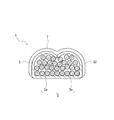
- 2 is a longitudinal sectional view taken along line AA of FIG. 3 is a longitudinal sectional view taken along line BB of FIG.
- FIG. 1 is a perspective view showing an embodiment of a covered electric wire with a terminal according to the present invention
- FIG. 2 is a longitudinal sectional view taken along line AA in FIG. 1
- FIG. 3 is a longitudinal sectional view taken along line BB in FIG. It is.
- the terminal-equipped covered electric wire 1 of the present embodiment is formed at the end of the covered electric wire 2 in which an aluminum alloy conductor 3 is covered with a covering material 4 made of polyvinyl chloride resin.
- a terminal metal fitting 5 made of a copper-based material that has been plated is crimped and connected.
- the contact portion 6 between the conductor 3 and the terminal fitting 5 is covered and sealed with a coating film of an anticorrosive 7.
- the portion covered with the coating film of the anticorrosive 7 is in a range indicated by a one-dot chain line.
- FIG. 1 shows the anticorrosive coating film 7 seen through.
- the anticorrosive 7 has a function as a protective film that prevents moisture or the like from entering the contact portion 6 of the dissimilar metal between the conductor 3 and the terminal fitting 5 from the outside and corroding the metal portion.
- the terminal metal fitting 5 is made by using a copper-based metal plate whose surface is tin-plated with brass as a base material, punching it into a predetermined shape in which the terminal metal fitting is developed, and bending the barrel portion etc. Is used. Therefore, the end surface of the terminal fitting 5 is in a state in which tin plating is not present and brass is exposed.
- the terminal fitting 5 is for crimping a tab-like connection portion 51 as a male terminal connected to a counterpart female terminal (not shown) and a covered electric wire extending from the base end of the connection portion 51.
- Barrel 54 (52, 53).
- the barrel 54 is composed of two crimping portions, a wire barrel 52 provided on the connection portion 51 side and an insulation barrel 53 provided on the conductor 3 side.
- the conductor 3 in a state where the end of the covered electric wire 2 is peeled off and exposed is crimped and crimped by a wire barrel 52.
- the crimping part of the conductor 3 and the terminal metal fitting 5 becomes the contact part 6 (refer FIG. 2, FIG. 3), and both are electrically connected.
- This contact portion 6 is in a state where the aluminum alloy of the conductor 3 and the dissimilar metal of tin plated brass of the terminal fitting 5 are in contact with each other.
- the insulation barrel 53 of the terminal fitting 5 is crimped by crimping around the covering material 4 of the covered electric wire 2.
- the crimp portion of the insulation barrel 53 is an electric wire fixing portion for fixing and holding the terminal fitting 5 to the end of the covered electric wire 2.
- the end of the terminal fitting 5 on the connection part 51 side is the front end
- the end on the insulation barrel 53 side is the rear end
- the front end is the front of the terminal-attached electric wire 1.
- the rear end side was the rear.
- the electric wire crimping surface side of the terminal metal fitting 5 was made into the surface, and the opposite surface side was made into the bottom face.
- the coated electric wire with a terminal before applying the anticorrosive 7 is in a state where a part of the conductor 3 is exposed to the outside at the contact portion 6 which is a connection portion between the conductor 3 and the terminal.
- the exposed portion of the conductor 3 is coated with the anticorrosive agent 7 so as to cover the contact portion 6 of the coated electric wire with terminal 1 and covered with the coating film of the anticorrosive agent 7.
- an ultraviolet curable acrylic resin adhesive composition containing an organic peroxide hereinafter sometimes referred to as an ultraviolet curable adhesive
- it is cured by ultraviolet irradiation and heating. It is formed as a cured product.
- the anticorrosive 7 is formed from an ultraviolet curable adhesive which is a composition of an ultraviolet curable acrylic resin, it is rapidly cured by application of ultraviolet rays after application, and even to the tip even if the viscosity is low. Inflow of the anticorrosive 7 can be prevented.
- the viscosity of the ultraviolet curable adhesive used for the anticorrosive 7 is preferably in the range of 1000 to 4000 mPa ⁇ s at room temperature from the viewpoint that it easily penetrates into gaps such as conductors during application.
- the ultraviolet curable adhesive basically includes the following components (A) and (B).
- acrylate oligomer various acrylate oligomers that are usually used as an ultraviolet curable adhesive and that can exhibit a function as an adhesive by ultraviolet curing can be used.
- the acrylate oligomer it is preferable to use a urethane acrylate oligomer from the viewpoint of easy viscosity adjustment, good adhesiveness, easy physical property preparation, and the like.
- the urethane acrylate oligomer a known urethane acrylate used for an ultraviolet curable adhesive can be used.
- thermosetting can be performed at a relatively low temperature by using an organic peroxide having a half-life temperature of 130 ° C. or less for 1 minute. Therefore, the heating temperature required for thermosetting can be suppressed. When the heating temperature of the anticorrosive agent is lowered, the adverse effect of the wire covering material upon heating can be reduced.
- the heating temperature for thermosetting the ultraviolet curable adhesive is increased.
- the plasticizer contained in the vinyl chloride resin is easy to bleed, the adhesive strength is reduced, the plasticizer is liable to smoke, and other additives contained in the vinyl chloride resin are volatilized and thinned.
- the vinyl chloride resin itself tends to be thermally deteriorated.
- the heating conditions at the time of heat-curing are conditions that do not cause much problems if the temperature is about 120 ° C. for about 10 minutes. If the 1-minute half-life temperature of an organic peroxide is 135 degrees C or less, it can fully cure an ultraviolet curable adhesive on said hardening conditions.
- the heating temperature is preferably in the range of 120 to 130 ° C.
- the heating time is preferably in the range of 5 to 10 minutes.
- the lower limit of the 1 minute half-life temperature of the organic peroxide is 100 ° C or higher. This is because if the one-minute half-life temperature of the organic peroxide is less than 100 ° C., there is a risk that the resin will harden during storage or application of the anticorrosive agent. When the temperature is 100 ° C. or higher, operations such as handling and application can be easily performed.
- the 1-minute half-life temperature is a temperature at which the amount of active oxygen becomes 1/2 in 1 minute when the original organic peroxide decomposes.
- organic peroxide peroxyesters, diacyl peroxides and the like are preferably used.
- examples of the organic peroxide include the following compounds. In parentheses are the 1 minute half-life temperatures. t-hexyl peroxide neodecanoate (100.9), t-butylperoxyneodecanoate (103.5), t-butylperoxyneoheptanoate (104.6), t-hexylperoxy Pivalate (109.1), t-butyl peroxypivalate (110.3), di (3,5,5-trimethylhexanoyl) peroxide (112.6), dilauroyl peroxide (116.4) 1,1,3,3-tetramethylbutylperoxy-2-ethylhexanoate (124.3), disuccinic acid peroxide (131.8), 2,5-dimethyl-2,5-di ( 2-ethylhexanoylperoxy) hexane (118.8),
- the amount of the organic peroxide is preferably in the range of 0.5 to 3 parts by mass with respect to 100 parts by mass of the acrylate oligomer. If the amount of the organic peroxide is large, the stability of the composition may be lowered, and if the amount of the organic peroxide is small, the heat curing may be insufficient.
- the photopolymerization initiator is not particularly limited as long as it is a compound that absorbs ultraviolet rays to initiate radical polymerization, and a conventionally known photopolymerization initiator can be used.
- blend acrylate monomers such as isobornyl (meth) acrylate
- an ultraviolet curable adhesive
- the UV curable adhesive may contain other additives in addition to the above components as long as the object of the present invention is not impaired.
- the other additives include anti-aging agents, adhesion-imparting agents, corrosion inhibitors, thixotropic agents, liquid preparation agents such as leveling agents, pigments, dyes, and inorganic fillers.
- the anticorrosive agent 7 obtained by curing the above-described ultraviolet curable adhesive may be a transparent or translucent resin.
- the coating thickness of the anticorrosive agent 7 is preferably applied in a range of 0.01 to 3 mm. If the coating thickness of the anticorrosive 7 becomes too thick, it may be difficult to insert the terminal fitting 5 into the connector of the mating terminal. Further, if the thickness of the anticorrosive coating film 7 becomes too thin, the anticorrosion performance may be insufficient.
- the UV curable adhesive of the anticorrosive 7 As a coating method when the UV curable adhesive of the anticorrosive 7 is applied to the contact portion between the conductor and the terminal fitting, known means such as a dropping method, a coating method, and an extrusion method can be used. Further, when applying the ultraviolet curable adhesive, the temperature of the anticorrosive may be adjusted by heating, cooling or the like.
- the anticorrosive 7 is in a state of completely covering at least the exposed portion of the conductor 3. Furthermore, the anticorrosive 7 coats the end of the coated electric wire 2 so that it slightly protrudes from the end of the conductor 3 to the connecting portion 51 side of the terminal fitting 5. The portion of the covered wire 2 where the conductor 3 is exposed is covered with the anticorrosive agent 7 so as not to be exposed to the outside. Further, the anticorrosive 7 covers the surface of the insulation barrel 53 and a part of the covering material 4 on the side of the covered electric wire 2. The coating material 4 side of the end surface of the insulation barrel 53 is coated with the anticorrosive 7.
- the tensile shear adhesive strength between the anticorrosive 7 and the covering material 4 is preferably 0.5 MPa or more. Moreover, it is preferable that the tensile shear adhesive strength of the anticorrosive 7 and the terminal metal fitting 5 is 0.5 Mpa or more. In order for the tensile shear adhesive strength of the anticorrosive to be 0.5 MPa or more, the type of urethane acrylate used in the ultraviolet curable adhesive may be appropriately selected according to the adherend. When the tensile shear adhesive strength of the anticorrosive is within the above range, it is possible to prevent the anticorrosion performance from being deteriorated due to shrinkage of the covering material after the terminal-attached electric wire is left at a high temperature, and the like.
- the tensile shear bond strength is a value measured at room temperature in accordance with JIS K6850.
- the conductor 3 of the covered electric wire 2 is a stranded wire formed by twisting a plurality of strands 3a.
- the stranded wire may be composed of one type of metal strand or may be composed of two or more types of metal strand.
- the twisted wire may contain the strand etc. which consist of organic fibers other than a metal strand.
- “consisting of one type of metal strand” means that all the metal strands constituting the stranded wire are made of the same metal material, and “consisting of two or more types of metal strands” This means that the wire contains metal wires made of different metal materials.
- the stranded wire may include a reinforcing wire (tension member) for reinforcing the covered electric wire.
- Examples of the material of the metal wire constituting the conductor 3 include copper, copper alloy, aluminum, or materials obtained by applying various platings to these materials in addition to the aluminum alloy. Moreover, as a material of the metal strand as a reinforcement wire, a copper alloy, titanium, tungsten, stainless steel etc. can be illustrated. Examples of the organic fiber as the reinforcing wire include Kevlar. As the metal strand of the conductor 3, it is preferable to use aluminum or an aluminum alloy from the viewpoint of reducing the weight of the electric wire.
- Examples of the material of the covering material 4 of the covered electric wire 2 include rubber, polyolefin, polyvinyl chloride resin (PVC), thermoplastic elastomer, and the like. These may be used alone or in admixture of two or more.
- Various additives may be appropriately added to the material of the covering material 4. Examples of the additive include a flame retardant, a filler, a colorant and the like. From the viewpoint of versatility, it is preferable to use a soft or semi-rigid polyvinyl chloride resin.
- the terminal fitting 5 As the material of the terminal fitting 5 (material of the base material), various copper alloys, copper, etc. can be used in addition to brass. Moreover, the terminal metal fitting 5 may be plated with various metals such as tin, nickel, and gold on a part of the surface (for example, a contact) or the whole.
- the coating material 4 at the tip of the coated electric wire 2 is peeled off, and the conductor 3 is exposed to a predetermined length, and then the coated electric wire 2 is plated as described above.
- the terminal fitting 5 subjected to bending or the like is crimped and crimped.
- the conductor 3 is crimped to the wire barrel 52 of the terminal fitting, and the covering material 4 is crimped to the insulation barrel 53 to connect the conductor 3 and the terminal fitting 5.
- an anticorrosive agent is applied to a predetermined range including a contact portion between the conductor 3 and the terminal fitting 5.
- the anticorrosive agent is irradiated with ultraviolet rays to cure the range where the irradiated light reaches. Curing to such an extent that the fluidity of the ultraviolet curable adhesive is lost by irradiation with ultraviolet rays. It is possible to prevent the ultraviolet curable adhesive from flowing into the tip side. Furthermore, the resin is heated and cured at a predetermined temperature for a predetermined time, and the uncured resin that does not reach ultraviolet rays is heated and cured. With the anticorrosive 7 obtained by curing the anticorrosive 7 with the ultraviolet curable adhesive, the terminal-coated electric wire 1 in which the contact portion 6 between the conductor 3 and the terminal fitting 5 is sealed is obtained.
- the wire harness of the present invention is formed by bundling a plurality of covered electric wires including the above-described covered electric wire with terminal 1.
- a part of the covered electric wire may be the covered electric wire 1 with a terminal of the present invention, or all may be the covered electric wire 1 with a terminal of the present invention.
- the plurality of covered electric wires may be bound by tape winding, or may be bound by being covered by an exterior part such as a round tube, a corrugated tube, or a protector. .
- the wire harness of the present invention is suitable for wiring in a vehicle such as an automobile, and particularly suitable for wiring in an engine room or a vehicle in a wet area.
- rust is likely to occur at the electrical connection portion between the conductor 3 and the terminal fitting 5 due to the influence of heat and water. Since the contact part 6 which is the electrical connection part of the conductor 3 and the terminal metal fitting 5 in the covered electric wire 1 with a terminal is covered with the anticorrosive agent 7, the wire harness of this invention can suppress generation
- Examples 1 to 3 and Comparative Examples 1 to 2 As an anticorrosive, an ultraviolet curable adhesive prepared by blending the organic peroxide shown in Table 1 with a urethane acrylate oligomer was prepared and used as an anticorrosive in Examples 1 to 3 and Comparative Examples 1 and 2. The compounding amounts of the organic peroxides in Examples 1 to 3 and Comparative Examples 1 to 2 were 1 part by mass with respect to 100 parts by mass of the urethane acrylate oligomer.
- tin-plated brass plates and soft vinyl chloride resin sheets are used as adherends, and the adhesive is sandwiched between adherends according to JIS K6850.
- a cured shear tensile test piece was prepared, a tensile test was performed, and a tensile shear bond strength was measured.
- a terminal-attached electric wire in which the contact portion between the conductor and the terminal fitting was sealed was produced, and the anticorrosive performance of the anticorrosive agent was evaluated.
- the curing conditions of the ultraviolet curable adhesives of Examples 1 to 3 and Comparative Examples 1 and 2 were all performed only by heating at 120 ° C. for 10 minutes.
- the coated electric wire 1 with a terminal of the said Example showed the example which used the tab-shaped male terminal as a terminal metal fitting, it is not limited to this.
- a covered electric wire with a terminal may use a female terminal as a terminal fitting.
- a tuning fork terminal or the like may be used as the terminal fitting.
- terminal metal fitting 5 may have no insulation barrel, the conductor and the covering material may be pressure-bonded with only one wire barrel, and the rear end of the wire barrel may be exposed to the outside.
- the barrel may be composed only of an insulation barrel.
- the method of connecting the conductor and the terminal fitting may be a method such as pressure welding, ultrasonic welding, or soldering.
- a single core wire may be used for a conductor.
Landscapes
- Insulated Conductors (AREA)
Abstract
絶縁電線の導体と端子金具との電線接続部の防食性能が優れている、端子付き被覆電線及びワイヤーハーネスを提供する。 導体3が被覆材4で被覆された被覆電線2の端部に、導体露出部を有し、前記導体露出部の前記導体3に端子金具5が接続され、前記導体3と前記端子金具4との接触部6が防食剤7により封止されている端子付き被覆電線1であって、前記防食剤7が有機過酸化物を含有する紫外線硬化型アクリル系樹脂から形成されたものであり、前記有機過酸化物として1分間半減期温度が100~135℃の範囲内のものを用いた。
Description
本発明は、端子付き被覆電線及びそれを用いたワイヤーハーネスに関し、さらに詳しくは、導体と端子金具との電気接続部の防食性に優れた端子付き被覆電線及びワイヤーハーネスに関するものである。
従来、自動車等の車両に配索される電線として、タフピッチ銅の軟質材等からなる導体の外周に被覆材を被覆してなる被覆電線が広く用いられている。この種の被覆電線の端末では、被覆材を皮剥ぎして露出させた導体に端子金具が接続されている。被覆電線の端末に電気接続された端子金具は、コネクタに挿入係止される。
自動車等の車両では、通常、端子付き被覆電線が複数本束ねられてワイヤーハーネスの形態で配索がなされる。エンジンルームや一部の室内環境等に、上記ワイヤーハーネスが配索される場合、熱および水の影響を受けて、導体と端子金具とが接触する電気接続部に錆が発生しやすくなる。
近年、自動車等の車両の軽量化により燃費効率を向上させようとする動きが加速しており、ワイヤーハーネスを構成する電線材料についても軽量化が求められている。そのため、導体にアルミニウムを用いることが検討されるようになってきている。
しかしながら端子金具は、電気特性に優れた銅又は銅合金が一般に用いられる。それ故、アルミ電線-銅端子金具の組み合わせ等で使用されることが多くなる。導体と端子金具との材質が異なると、その電気接続部で異種金属接触による腐食が発生する。この種の腐食は、導体と端子金具との材質が同じである場合よりも起こりやすい。そのため、電気接続部を確実に防食できる防食剤が必要となる。
上記電気接続部における腐食を防止するため、例えば、特許文献1には、粘度の異なる2種類以上の樹脂を使用し、導体に接続された電線先端部を封止する技術が公知である。
特許文献1に記載の防食方法は、端子先端部へ樹脂が流れ込むことによる接触不良を防ぐために粘度の高い樹脂を使用すると共に、狭い隙間に樹脂を浸透させるために粘度の低い樹脂を使用し、粘度の異なる2種類以上の樹脂を使用する必要があった。このように、使用する樹脂の種類が多くなると、材料を管理する手間がかかるという問題がある。
また、先端等に樹脂が流れ込むのをを防止するための他の手段として、防食剤に紫外線硬化型樹脂を用いて、樹脂の硬化を速やかに行うことが考えられる。しかし、隙間の内部に浸透させた樹脂には硬化のための紫外線が届かないため、浸透部分の樹脂が硬化不良となってしまうという問題がある。
またワイヤーハーネス等が車載された高温環境下では、防食剤の被覆樹脂の収縮が起こり、隙間に充填した防食剤と電線被覆の間で剥離してしまい、その防食剤が剥離した部分から電気接続部に水が浸入してしまうという問題があった。
本発明の目的は、上記従来技術の問題点を解決しようとするものであり、被覆電線と端子金具との電線接続部の防食性能が優れている端子付き被覆電線及びワイヤーハーネスを提供することにある。
上記課題を解決するために、本発明の端子付き被覆電線は、
導体が被覆材で被覆された被覆電線の端部に、前記被覆材が剥離されて前記導体が露出した導体露出部を有し、前記導体露出部の前記導体に端子金具が接続され、前記導体と前記端子金具との接触部が防食剤により封止されている端子付き被覆電線であって、
前記防食剤が有機過酸化物を含有する紫外線硬化型アクリル系樹脂から形成されたものであり、前記有機過酸化物の1分間半減期温度が100~135℃の範囲内であることを要旨とするものである。
導体が被覆材で被覆された被覆電線の端部に、前記被覆材が剥離されて前記導体が露出した導体露出部を有し、前記導体露出部の前記導体に端子金具が接続され、前記導体と前記端子金具との接触部が防食剤により封止されている端子付き被覆電線であって、
前記防食剤が有機過酸化物を含有する紫外線硬化型アクリル系樹脂から形成されたものであり、前記有機過酸化物の1分間半減期温度が100~135℃の範囲内であることを要旨とするものである。
本発明の端子付き被覆電線は、前記紫外線硬化型アクリル系樹脂が、ウレタンアクリレートオリゴマーを含有することをが好ましい。
本発明の端子付き被覆電線は、前記防食剤と前記被覆材の引張せん断接着強さが、0.5MPa以上であることをことが好ましい。
本発明の端子付き被覆電線は、前記防食剤と前記端子金具の引張りせん断接着強さが、0.5MPa以上であることが好ましい。
本発明の端子付き被覆電線は、前記被覆電線の被覆材が、塩化ビニル樹脂系材料であり、前記防食剤が前記被覆電線の端部の前記被覆材を覆っていることが好ましい。
本発明の端子付き被覆電線は、前記端子金具が、銅系材料の表面にすずめっきが施されていることが好ましい。
本発明の端子付き被覆電線は、前記導体が、アルミニウム系材料よりなる素線を有していることが好ましい。
本発明のワイヤーハーネスは、上記記載の端子付き被覆電線を有することを要旨とするものである。
本発明の端子付き被覆電線は、防食剤が有機過酸化物を含有する紫外線硬化型アクリル系樹脂から形成されたものであり、前記有機過酸化物の1分間半減期温度が100~135℃の範囲内である構成を採用したことにより、従来の端子付き被覆電線と比較して、防食剤として紫外線硬化型樹脂を用いたことにより、速硬化が可能であり、粘度がある程度低くても、先端部等の不要な部分への防食剤の流れ込みを防止することが可能である。
また防食剤として1分間半減期温度が100~135℃の範囲内である有機過酸化物を含有するものであるから、紫外線等の照射光が届かない隙間部分等を、熱硬化により完全に硬化させることが可能であり、防食性に優れている。そのため、防食剤として、粘度の異なる複数の樹脂を用いたりする必要がなく、1種類の材料を用いればよいので、材料の管理等が容易である。
また防食剤に、1分間半減期温度が130℃以下の有機過酸化物を用いたことにより、熱硬化の際に必要な加熱温度を抑制することが可能であり、防食剤の硬化時の熱により電線被覆材が受ける悪影響を小さくすることができる。また防食剤の有機過酸化物の1分間半減期温度が100℃以上であるから、防食剤の保存や塗布等の際に樹脂が硬化してしまう不具合を防止して、取扱いや塗布等の作業を容易に行うことが可能である。
以下、図面を用いて本発明の実施例を詳細に説明する。図1は本発明の端子付き被覆電線の一実施例を示す斜視図であり、図2は図1のA-A線縦断面図であり、図3は図2のB-B線縦断面図である。図1~図3に示すように、本実施例の端子付き被覆電線1は、アルミニウム合金製の導体3がポリ塩化ビニル樹脂よりなる被覆材4により被覆された被覆電線2の端部に、すずめっきが施された銅系材料からなる端子金具5が、圧着されて接続されている。
導体3と端子金具5との接触部6は、防食剤7の塗膜により被覆されて封止されている。図1の端子付き電線において、防食剤7の塗膜が被覆している部分は、一点鎖線で示した範囲である。尚、図1は防食剤の塗膜7を透視した状態で示している。防食剤7は、導体3と端子金具5との異種金属の接触部6に、外部から水分等が侵入して金属部分が腐食するのを防止する保護膜としての機能を有している。
端子金具5は、黄銅を母材として表面にすずめっきされた銅系金属板材を用い、端子金具が展開された所定の形状に打ち抜いたものを作製し、バレルの部分等を折り曲げて作製したものを用いている。そのため、端子金具5の端面はすずめっきが存在せず、黄銅が露出した状態になっている。
端子金具5は、相手側メス端子(図示しない)に接続されるオス端子としてのタブ状の接続部51と、該接続部51の基端に延設形成されている、被覆電線を圧着するためのバレル54(52、53)とを有する。バレル54は、接続部51側に設けられたワイヤバレル52と、導体3側に設けられたインシュレーションバレル53の二つの圧着部から構成されている。
端子付き被覆電線1は、被覆電線2の端末が皮剥されて露出した状態の導体3が、ワイヤバレル52により加締められ圧着している。導体3と端子金具5の圧着部が接触部6(図2、図3参照)となって、両者は電気的に接続されている。この接触部6は、導体3のアルミニウム合金と端子金具5のすずめっきされた黄銅の異種金属とが接触した状態になっている。
また端子金具5のインシュレーションバレル53は、被覆電線2の被覆材4の周囲に加締められて圧着している。このインシュレーションバレル53の圧着部は、端子金具5を被覆電線2の端末に固定、保持するための電線固定部となっている。
尚、本実施例では、便宜的に、端子金具5の接続部51側端部を先端とし、インシュレーションバレル53側の端部を後端とし、前記先端側を端子付き電線1の前方とし、前記後端側を後方とした。また、端子金具5の電線圧着面側を表面とし、反対面側を底面とした。
防食剤7を塗布する前の端子付き被覆電線は、導体3と端子の接続部分である接触部6において、導体3の一部が外部に露出した状態になっている。そして図1~3に示すように、導体3の露出した部分は、防食剤7が端子付き被覆電線1の上記接触部6を覆うように塗布されて、防食剤7の塗膜により覆われている。防食剤7は、有機過酸化物を含有する紫外線硬化型アクリル樹脂の接着剤組成物(以下、紫外線硬化型接着剤ということもある)が用いられ、塗布後、紫外線照射と加熱により硬化させた硬化物として形成されている。
防食剤7が紫外線硬化型アクリル系樹脂の組成物である紫外線硬化型接着剤から形成されたものであるから、塗布後、紫外線の照射により、速硬化して、粘度が低くても先端部への防食剤7の流れ込みを防ぐことができる。防食剤7に用いられる紫外線硬化型接着剤の粘度は、塗布時に導体等の隙間に浸透しやすいという点から、常温で、1000~4000mPa・sの範囲内が好ましい。
紫外線硬化型接着剤は、基本的に下記の(A)、(B)成分を含んでいる。
(A)アクリレートオリゴマー(B)有機過酸化物
(A)アクリレートオリゴマー(B)有機過酸化物
(A)アクリレートオリゴマーは、通常、紫外線硬化型接着剤として用いられる、紫外線硬化により接着剤としての機能を発現することが可能である各種のアクリレートオリゴマーを用いることができる。アクリレートオリゴマーは、粘度の調製が容易である点や、接着性が良好である点や、物性の調製が容易である点等から、ウレタンアクリレートオリゴマーを用いることが好ましい。ウレタンアクリレートオリゴマーは、紫外線硬化型接着剤に用いられる公知のウレタンアクリレートを利用することができる。
(B)有機過酸化物は、1分間半減期温度が100~135℃のものが用いられる。紫外線硬化型接着剤が、有機過酸化物を含有するものであるから、紫外線等の照射光が届かない隙間部分等を、熱硬化により完全に硬化させることが可能であり、防食性に優れている。また1分間半減期温度が130℃以下の有機過酸化物を用いたことにより、熱硬化を比較的低い温度で行うことが可能である。そのため、熱硬化の際に必要な加熱温度を抑制することができる。防食剤の加熱温度が低くなると、電線被覆材が加熱により受ける悪影響を小さくすることができる。
例えば、被覆電線2の被覆材4に軟質又は半硬質の塩化ビニル樹脂を使用した場合、紫外線硬化型接着剤を熱硬化させるための加熱温度が高くなると、種々の問題が発生する。例えば、塩化ビニル樹脂中に含まれる可塑剤がブリードし易くなって、接着強さが低下する、可塑剤が発煙し易くなる、塩化ビニル樹脂中に含まれる他の添加剤が揮散して肉痩せし易くなる、塩化ビニル樹脂自体が熱劣化し易くなる等の問題がある。上記の点を鑑みると、加熱硬化の際の加熱条件は、120℃、10分程度の温度であれば、あまり問題の発生しない条件であることが、これでの経験により判っている。有機過酸化物の1分間半減期温度が135℃以下であれば、上記の硬化条件で紫外線硬化型接着剤を十分に硬化させることが可能である。
加熱硬化の際の加熱条件としては、加熱温度が120~130℃の範囲内であり、加熱時間が5~10分の範囲内で行うのが好ましい。
有機過酸化物の1分間半減期温度の下限は100℃以上である。これは有機過酸化物の1分間半減期温度が100℃未満になると、防食剤の保存や塗布等の際に樹脂が硬化してしまう不具合が発生する恐れがあるためであり、1分間半減期温度が100℃以上であれば、取扱いや塗布等の作業を容易に行うことが可能である。1分間半減期温度は、もとの有機過酸化物が分解して1分間でその活性酸素量が1/2になる温度である。
上記の有機過酸化物としては、パーオキシエステル、ジアシルパーオキサイド等が好ましく用いられる。有機過酸化物として、例えば、下記の化合物が挙げられる。括弧内は1分間半減期温度である。t‐ヘキシルパーオキサイドネオデカノエート(100.9)、t‐ブチルパーオキシネオデカノエート(103.5)、t‐ブチルパーオキシネオヘプタノエート(104.6)、t‐ヘキシルパーオキシピバレート(109.1)、t‐ブチルパーオキシピバレート(110.3)、ジ(3,5,5‐トリメチルヘキサノイル)パーオキサイド(112.6)、ジラウロイルパーオキサイド(116.4)、1,1,3,3‐テトラメチルブチルパーオキシ‐2‐エチルヘキサノエート(124.3)、ジサクシニックアシドパーオキサイド(131.8)、2,5‐ジメチル‐2,5‐ジ(2‐エチルヘキサノイルパーオキシ)ヘキサン(118.8)、t‐ヘキシルパーオキシ‐2‐エチルヘキサノエート(132.6)、t‐ブチルパーオキシ‐2‐エチルヘキサノエート(134.0)、ジ(3‐メチルベンゾイル)パーオキサイド、ベンゾイル(3‐メチルベンゾイル)パーオキサイド、ジベンゾイルパーオキサイド等(130~135)。
紫外線硬化型接着剤において、上記有機過酸化物の配合量は、アクリレートオリゴマー100質量部に対し、0.5~3質量部の範囲内が好ましい。有機過酸化物の配合量が多いと組成物の安定性が低下する恐れがあり、有機過酸化物の配合量が少ないと、熱硬化が不十分になる恐れがある。
紫外線硬化型接着剤において、光重合開始剤を配合することが好ましい。光重合開始剤は、紫外線を吸収してラジカル重合を開始させる化合物であれば特に制限されることなく、従来から公知のものを用いることができる。
また紫外線硬化型接着剤には、イソボルニル(メタ)アクリレート等のアクリレートモノマーを配合してもよい。
紫外線硬化型接着剤は、本発明の目的を阻害しない範囲であれば、上記の成分以外に、他の添加剤が配合されていてもよい。上記他の添加剤としては、老化防止剤、密着性付与剤、腐食防止剤、チキソ性付与剤、レべリング剤等の液性調製剤、顔料、染料、無機フィラー等が挙げられる。
上記の紫外線硬化型接着剤を硬化して得られる防食剤7は、透明又は半透明の樹脂のいずれでもよい。
防食剤7の塗膜の厚みは、0.01~3mmの範囲となるように塗布するのが好ましい。防食剤7の塗膜の厚みが厚くなりすぎると、端子金具5を相手側端子のコネクタへ挿入し難くなる恐れがある。また防食剤の塗膜7の厚みが薄くなりすぎると防食性能が不十分となる恐れがある。
防食剤7の紫外線硬化型接着剤を導体と端子金具の接触部に塗布する際の塗布方法は、滴下法、塗布法、押し出し法等の公知の手段を用いることができる。また紫外線硬化型接着剤の塗布の際、防食剤を加熱、冷却等により温度調節してもよい。
防食剤7は、少なくとも導体3の露出部分を完全に被覆する状態になっている。更に防食剤7は、被覆電線2の先端側は、導体3の先端から端子金具5の接続部51側に少しはみ出すように被覆している。被覆電線2の導体3が露出した部分は、防食剤7によって覆われていて、外部に露出しないようになっている。また、防食剤7は、被覆電線2側は、インシュレーションバレル53の表面と被覆材4の一部を被覆している。インシュレーションバレル53の端面の被覆材4側は、防食剤7により被覆されている。
防食剤7と被覆材4の引張せん断接着強さは、0.5MPa以上であることが好ましい。また防食剤7と端子金具5の引張りせん断接着強さは、0.5MPa以上であることが好ましい。防食剤の引張せん断接着強さが、0.5MPa以上とするためには、紫外線硬化型接着剤に用いられるウレタンアクリレートの種類等を、被着材に合わせて適宜選択すればよい。防食剤の引張せん断接着強さが上記範囲であれば、端子付き電線が高温放置後に被覆材が収縮等して、隙間が発生して、防食性能が低下するのを防止できる。上記の引張せん断接着強さは、JIS K6850に準拠して、常温で測定される値である。
被覆電線2の導体3は、複数の素線3aが撚り合わされてなる撚線が用いられる。この場合、撚線は、1種の金属素線より構成されていても良いし、2種以上の金属素線より構成されていても良い。また、撚線は、金属素線以外に、有機繊維よりなる素線等を含んでいても良い。なお、1種の金属素線より構成されるとは、撚線を構成する全ての金属素線が同じ金属材料よりなることをいい、2種以上の金属素線より構成されるとは、撚線中に互いに異なる金属材料よりなる金属素線を含んでいることをいう。撚線中には、被覆電線を補強するための補強線(テンションメンバ)等が含まれていても良い。
上記導体3を構成する金属素線の材料としては、アルミニウム合金以外に、銅、銅合金、アルミニウムもしくはこれらの材料に各種めっきが施された材料等を例示することができる。また、補強線としての金属素線の材料としては、銅合金、チタン、タングステン、ステンレス等を例示することができる。また、補強線としての有機繊維としては、ケブラー等を挙げることができる。導体3の金属素線としては、電線の軽量化等の点からアルミニウム又はアルミニウム合金を用いるのが好ましい。
被覆電線2の被覆材4の材料としては、例えば、ゴム、ポリオレフィン、ポリ塩化ビニル樹脂(PVC)、熱可塑性エラストマー等が挙げられる。これらは単独で用いても良いし、二種以上を混合して用いても良い。被覆材4の材料中には、適宜、各種添加剤が添加されていても良い。添加剤としては、難燃剤、充填剤、着色剤等を挙げることができる。被覆材は汎用性がある点から、軟質或いは半硬質のポリ塩化ビニル樹脂を用いるのが好ましい。
端子金具5の材料(母材の材料)としては、黄銅以外に、各種銅合金、銅等を用いることができる。また端子金具5は、表面の一部(例えば接点)もしくは全体に、すず、ニッケル、金等の各種金属によりめっきが施されていても良い。
端子付き被覆電線1を製造するには、先ず被覆電線2の先端の被覆材4を皮剥ぎして導体3を所定の長さだけ露出させた被覆電線2の端末に、前記したようにめっきされた母材を打ち抜いた後に、曲げ加工等を施した端子金具5を加締めて圧着する。端子金具のワイヤバレル52に導体3を圧着し、インシュレーションバレル53に被覆材4を圧着して、導体3と端子金具5を接続する。次いで、導体3と端子金具5との接触部を含む所定の範囲に防食剤を塗布する。次いで、冷防食剤に紫外線を照射して、照射光が届く範囲を硬化させる。紫外線の照射により、紫外線硬化型接着剤の流動性がなくなる程度に硬化させる。紫外線硬化型接着剤が先端側に流れ込むのを防止できる。更に、所定の温度で所定の時間加熱して、紫外線の届かない未硬化の部分の樹脂を加熱硬化させる。防食剤7が紫外線硬化型接着剤が硬化した防食剤7により、導体3と端子金具5の接触部6が封止された端子付き被覆電線1が得られる。
以下、本発明のワイヤーハーネスについて説明する。本発明のワイヤーハーネスは、上記端子付き被覆電線1を含む複数本の被覆電線を束ねて結束したものである。ワイヤーハーネスにおいては、被覆電線のうちの一部が本発明の端子付き被覆電線1であっても良いし、全てが本発明の端子付き被覆電線1であっても良い。
ワイヤーハーネスにおいて、複数本の被覆電線は、テープ巻きにより結束されていても良いし、或いは、丸チューブ、コルゲートチューブ、プロテクタ等の外装部品により外装されることで結束されていても、いずれでも良い。
本発明のワイヤーハーネスは、自動車等の車両に配索されるものとして好適であり、特に、被水領域のエンジンルームや車内に配索されるものとして好適である。ワイヤーハーネスがこのような場所に配索された場合、熱および水の影響を受けて、導体3と端子金具5との電気接続部に錆が発生し易くなる。本発明のワイヤーハーネスは、端子付き被覆電線1における導体3と端子金具5との電気接続部である接触部6が防食剤7に覆われているので、錆の発生を効果的に抑えることができる。
以下に本発明の実施例、比較例を示す。なお、本発明はこれら実施例によって限定されるものではない。
実施例1~3、比較例1~2
防食剤として表1に示す有機過酸化物をウレタンアクリレートオリゴマーに配合した紫外線硬化型接着剤を調製して、実施例1~3、比較例1~2の防食剤として用いた。実施例1~3、比較例1~2の有機過酸化物の配合量は、ウレタンアクリレートオリゴマー100質量部に対し、1質量部とした。この紫外線硬化型接着剤を用いて、すずめっき黄銅板、軟質塩化ビニル樹脂シートを被着体として、それぞれ、JIS K6850に準拠して、被着体の間に接着剤を挟んで該接着剤を硬化させたせん断引張試験片を作成して、引張試験を行い、引張せん断接着強さを測定した。また実施例1~3、比較例1、2の防食剤を用いて導体と端子金具の接触部を封止した端子付き電線を作製して、防食剤の防食性能を評価した。実施例1~3、比較例1、2の紫外線硬化型接着剤の硬化条件は、全て、120℃×10分間の加熱のみで行った。
防食剤として表1に示す有機過酸化物をウレタンアクリレートオリゴマーに配合した紫外線硬化型接着剤を調製して、実施例1~3、比較例1~2の防食剤として用いた。実施例1~3、比較例1~2の有機過酸化物の配合量は、ウレタンアクリレートオリゴマー100質量部に対し、1質量部とした。この紫外線硬化型接着剤を用いて、すずめっき黄銅板、軟質塩化ビニル樹脂シートを被着体として、それぞれ、JIS K6850に準拠して、被着体の間に接着剤を挟んで該接着剤を硬化させたせん断引張試験片を作成して、引張試験を行い、引張せん断接着強さを測定した。また実施例1~3、比較例1、2の防食剤を用いて導体と端子金具の接触部を封止した端子付き電線を作製して、防食剤の防食性能を評価した。実施例1~3、比較例1、2の紫外線硬化型接着剤の硬化条件は、全て、120℃×10分間の加熱のみで行った。
〔引張せん断接着強さ試験〕
・試験片サイズ:25mm×80mm×厚さ0.5mm
・貼り合わせ面積:25mm×12.5mm
・引張速度:100mm/min
・試験片材料:すずめっき黄銅板、軟質塩化ビニル樹脂シート(下記の組成)
・試験片サイズ:25mm×80mm×厚さ0.5mm
・貼り合わせ面積:25mm×12.5mm
・引張速度:100mm/min
・試験片材料:すずめっき黄銅板、軟質塩化ビニル樹脂シート(下記の組成)
〔軟質ポリ塩化ビニル樹脂シートの調製〕
ポリ塩化ビニル(重合度1300)100質量部に対して、可塑剤としてジイソノニルフタレート40質量部、充填剤として重質炭酸カルシウム20質量部、安定剤としてカルシウム亜鉛系安定剤5質量部をオープンロールにより180℃で混合し、ペレタイザーにてペレット状に成形することにより、ポリ塩化ビニル組成物を調製した。次いで、射出成型機で上記組成物を厚さ0.5mmのシート状に成形し、所定の大きさに切断して試験片とした。
ポリ塩化ビニル(重合度1300)100質量部に対して、可塑剤としてジイソノニルフタレート40質量部、充填剤として重質炭酸カルシウム20質量部、安定剤としてカルシウム亜鉛系安定剤5質量部をオープンロールにより180℃で混合し、ペレタイザーにてペレット状に成形することにより、ポリ塩化ビニル組成物を調製した。次いで、射出成型機で上記組成物を厚さ0.5mmのシート状に成形し、所定の大きさに切断して試験片とした。
〔防食性能試験方法〕
防食性能は、図1~3に示すように形成した端子付き電線を作製して、JISZ2371に準拠して試験を行った。試験片を塩水噴霧(35℃×95%RH×35時間)した後、接触部の腐食状態を観察した。その結果、アルミニウム導体が腐食していない場合を良好(○)とし、アルミニウム導体が腐食していた場合を不良(×)と判断した。
防食性能は、図1~3に示すように形成した端子付き電線を作製して、JISZ2371に準拠して試験を行った。試験片を塩水噴霧(35℃×95%RH×35時間)した後、接触部の腐食状態を観察した。その結果、アルミニウム導体が腐食していない場合を良好(○)とし、アルミニウム導体が腐食していた場合を不良(×)と判断した。
〔防食試験結果について〕
表1に示すように、実施例1~3は有機過酸化物の1分間半減期温度が100~135℃の範囲内であり、防食性能が優れ、接着強さも良好であった。これに対し、比較例1は有機過酸化物の1分間半減期温度が135℃を超えているため、120℃×10分の加熱では、未硬化であった。比較例2は加熱温度を140℃まで上げた場合、十分硬化させることができ、防食性能は良好であったが、引張せん断接着強さが低くなってしまった。

表1に示すように、実施例1~3は有機過酸化物の1分間半減期温度が100~135℃の範囲内であり、防食性能が優れ、接着強さも良好であった。これに対し、比較例1は有機過酸化物の1分間半減期温度が135℃を超えているため、120℃×10分の加熱では、未硬化であった。比較例2は加熱温度を140℃まで上げた場合、十分硬化させることができ、防食性能は良好であったが、引張せん断接着強さが低くなってしまった。
以上、本発明の実施の形態について詳細に説明したが、本発明は上記実施の形態に何ら限定されるものではなく、本発明の要旨を逸脱しない範囲で種々の改変が可能である。
例えば上記実施例の端子付き被覆電線1は、端子金具としてタブ状のオス端子を用いた例を示したが、これに限定されるものではない。例えば端子付き被覆電線は、端子金具としてメス端子を用いたものでもよい。また、端子金具として音叉端子等を用いても良い。
また、端子金具5は、インシュレーションバレルを有しないで、一つのワイヤバレルのみで導体と被覆材が圧着され、ワイヤバレルの後端が外部に露出しているものであっても良い。
また、バレルはインシュレーションバレルのみから構成してもよい。その場合、導体と端子金具の接続方法としては、圧接抵抗溶接、超音波溶接、ハンダ付け等の方法であっても良い。また、上記実施例では導体として撚線を用いたが、導体は単芯線を用いてもよい。
Claims (8)
- 導体が被覆材で被覆された被覆電線の端部に、前記被覆材が剥離されて前記導体が露出した導体露出部を有し、前記導体露出部の前記導体に端子金具が接続され、前記導体と前記端子金具との接触部が防食剤により封止されている端子付き被覆電線であって、
前記防食剤が有機過酸化物を含有する紫外線硬化型アクリル系樹脂から形成されたものであり、前記有機過酸化物の1分間半減期温度が100~135℃の範囲内であることを特徴とする端子付き被覆電線。 - 前記紫外線硬化型アクリル系樹脂が、ウレタンアクリレートオリゴマーを含有することを特徴とする請求項1に記載の端子付き被覆電線。
- 前記防食剤と前記被覆材の引張せん断接着強さが、0.5MPa以上であることをことを特徴とする請求項1又は2に記載の端子付き被覆電線。
- 前記防食剤と前記端子金具の引張りせん断接着強さが、0.5MPa以上であることを特徴とする請求項1~3のいずれか1項に記載の端子付き被覆電線。
- 前記被覆電線の被覆材が、塩化ビニル樹脂系材料であり、前記防食剤が前記被覆電線の端部の前記被覆材を覆っていることを特徴とする請求項1~4のいずれか1項に記載の端子付き被覆電線。
- 前記端子金具が、銅系材料の表面にすずめっきが施されていることを特徴とする請求項1~5のいずれか1項に記載の端子付き被覆電線。
- 前記導体が、アルミニウム系材料よりなる素線を有していることを特徴とする請求項1~6のいずれか1項に記載の端子付き被覆電線。
- 請求項1~7のいずれか1項に記載の端子付き被覆電線を有することを特徴とするワイヤーハーネス。
Applications Claiming Priority (2)
| Application Number | Priority Date | Filing Date | Title |
|---|---|---|---|
| JP2014-241338 | 2014-11-28 | ||
| JP2014241338A JP2016103415A (ja) | 2014-11-28 | 2014-11-28 | 端子付き被覆電線 |
Publications (1)
| Publication Number | Publication Date |
|---|---|
| WO2016084580A1 true WO2016084580A1 (ja) | 2016-06-02 |
Family
ID=56074150
Family Applications (1)
| Application Number | Title | Priority Date | Filing Date |
|---|---|---|---|
| PCT/JP2015/081287 Ceased WO2016084580A1 (ja) | 2014-11-28 | 2015-11-06 | 端子付き被覆電線 |
Country Status (2)
| Country | Link |
|---|---|
| JP (1) | JP2016103415A (ja) |
| WO (1) | WO2016084580A1 (ja) |
Cited By (1)
| Publication number | Priority date | Publication date | Assignee | Title |
|---|---|---|---|---|
| JP2023035731A (ja) * | 2021-09-01 | 2023-03-13 | ネクスジェン株式会社 | 造血幹細胞培養組成物 |
Citations (6)
| Publication number | Priority date | Publication date | Assignee | Title |
|---|---|---|---|---|
| JPH03124716A (ja) * | 1989-10-09 | 1991-05-28 | Nippon Oil & Fats Co Ltd | 硬化剤組成物 |
| JP2000327954A (ja) * | 1999-04-16 | 2000-11-28 | Dow Corning Corp | 熱硬化性コーティング組成物 |
| JP2011256429A (ja) * | 2010-06-09 | 2011-12-22 | Autonetworks Technologies Ltd | 防食剤、端子付き被覆電線およびワイヤーハーネス |
| JP2012028152A (ja) * | 2010-07-23 | 2012-02-09 | Auto Network Gijutsu Kenkyusho:Kk | ワイヤーハーネスの端末構造 |
| JP2013214476A (ja) * | 2012-04-04 | 2013-10-17 | Yazaki Corp | 端子付き電線 |
| US20140329962A1 (en) * | 2011-12-08 | 2014-11-06 | Ocv Intellectual Capital, Llc | Fiber reinforced resin molding compound and manufacturing method for fiber reinforced resin molded article therefrom |
-
2014
- 2014-11-28 JP JP2014241338A patent/JP2016103415A/ja active Pending
-
2015
- 2015-11-06 WO PCT/JP2015/081287 patent/WO2016084580A1/ja not_active Ceased
Patent Citations (6)
| Publication number | Priority date | Publication date | Assignee | Title |
|---|---|---|---|---|
| JPH03124716A (ja) * | 1989-10-09 | 1991-05-28 | Nippon Oil & Fats Co Ltd | 硬化剤組成物 |
| JP2000327954A (ja) * | 1999-04-16 | 2000-11-28 | Dow Corning Corp | 熱硬化性コーティング組成物 |
| JP2011256429A (ja) * | 2010-06-09 | 2011-12-22 | Autonetworks Technologies Ltd | 防食剤、端子付き被覆電線およびワイヤーハーネス |
| JP2012028152A (ja) * | 2010-07-23 | 2012-02-09 | Auto Network Gijutsu Kenkyusho:Kk | ワイヤーハーネスの端末構造 |
| US20140329962A1 (en) * | 2011-12-08 | 2014-11-06 | Ocv Intellectual Capital, Llc | Fiber reinforced resin molding compound and manufacturing method for fiber reinforced resin molded article therefrom |
| JP2013214476A (ja) * | 2012-04-04 | 2013-10-17 | Yazaki Corp | 端子付き電線 |
Cited By (1)
| Publication number | Priority date | Publication date | Assignee | Title |
|---|---|---|---|---|
| JP2023035731A (ja) * | 2021-09-01 | 2023-03-13 | ネクスジェン株式会社 | 造血幹細胞培養組成物 |
Also Published As
| Publication number | Publication date |
|---|---|
| JP2016103415A (ja) | 2016-06-02 |
Similar Documents
| Publication | Publication Date | Title |
|---|---|---|
| JP5095705B2 (ja) | 端子付き被覆電線およびワイヤーハーネス | |
| JP5123991B2 (ja) | 防食剤、端子付き被覆電線およびワイヤーハーネス | |
| JP5741737B2 (ja) | 防食剤、端子付き被覆電線及びワイヤーハーネス | |
| JP2011179101A (ja) | 防食剤、端子付き被覆電線およびワイヤーハーネス | |
| JP2012001740A (ja) | 防食剤、端子付き被覆電線およびワイヤーハーネス | |
| JP6056584B2 (ja) | 端子付き被覆電線、ワイヤーハーネス、及び防食剤 | |
| JP6131888B2 (ja) | 端子付き被覆電線及びワイヤーハーネス | |
| JP6206240B2 (ja) | 端子付き被覆電線、その製造方法及びワイヤーハーネス | |
| US10020093B2 (en) | Terminal-equipped coated wire | |
| JP6111997B2 (ja) | 防食剤、端子付き被覆電線及びワイヤーハーネス | |
| JP2013254577A (ja) | 端子付き被覆電線及びワイヤーハーネス | |
| JP6036641B2 (ja) | 防食剤、端子付き被覆電線及びワイヤーハーネス | |
| JP2015174995A (ja) | 粘着剤組成物、防食端子及び端子付き被覆電線 | |
| JP6131893B2 (ja) | 端子付き電線及びそれに用いる粘着剤 | |
| WO2016084580A1 (ja) | 端子付き被覆電線 | |
| JP2013025932A (ja) | 防食剤、端子付き被覆電線およびワイヤーハーネス | |
| JP2013025931A (ja) | 防食剤、端子付き被覆電線およびワイヤーハーネス | |
| JP6040924B2 (ja) | 端子付き被覆電線およびワイヤーハーネス | |
| JP6107620B2 (ja) | 端子付き被覆電線及びワイヤーハーネス | |
| JP6260363B2 (ja) | 端子付き被覆電線 | |
| JP2013149418A (ja) | 端子付き電線および端子付き電線の製造方法 | |
| JP2013067847A (ja) | 防食剤、端子付き被覆電線及びワイヤーハーネス | |
| JP2014110151A (ja) | 端子付き被覆電線、ワイヤーハーネス、および防食剤 | |
| JP2015176841A (ja) | 端子付き被覆電線およびワイヤーハーネス | |
| WO2014132685A1 (ja) | 端子付き被覆電線および端子付き被覆電線の製造方法 |
Legal Events
| Date | Code | Title | Description |
|---|---|---|---|
| 121 | Ep: the epo has been informed by wipo that ep was designated in this application |
Ref document number: 15863584 Country of ref document: EP Kind code of ref document: A1 |
|
| NENP | Non-entry into the national phase |
Ref country code: DE |
|
| 122 | Ep: pct application non-entry in european phase |
Ref document number: 15863584 Country of ref document: EP Kind code of ref document: A1 |