WO2016084504A1 - Dispositif d'aide au diagnostic et procédé d'affichage d'informations d'aide au diagnostic - Google Patents
Dispositif d'aide au diagnostic et procédé d'affichage d'informations d'aide au diagnostic Download PDFInfo
- Publication number
- WO2016084504A1 WO2016084504A1 PCT/JP2015/078992 JP2015078992W WO2016084504A1 WO 2016084504 A1 WO2016084504 A1 WO 2016084504A1 JP 2015078992 W JP2015078992 W JP 2015078992W WO 2016084504 A1 WO2016084504 A1 WO 2016084504A1
- Authority
- WO
- WIPO (PCT)
- Prior art keywords
- value
- region
- fluorescence
- image
- processing unit
- Prior art date
Links
Images


Classifications
-
- A—HUMAN NECESSITIES
- A61—MEDICAL OR VETERINARY SCIENCE; HYGIENE
- A61B—DIAGNOSIS; SURGERY; IDENTIFICATION
- A61B1/00—Instruments for performing medical examinations of the interior of cavities or tubes of the body by visual or photographical inspection, e.g. endoscopes; Illuminating arrangements therefor
- A61B1/04—Instruments for performing medical examinations of the interior of cavities or tubes of the body by visual or photographical inspection, e.g. endoscopes; Illuminating arrangements therefor combined with photographic or television appliances
- A61B1/043—Instruments for performing medical examinations of the interior of cavities or tubes of the body by visual or photographical inspection, e.g. endoscopes; Illuminating arrangements therefor combined with photographic or television appliances for fluorescence imaging
-
- A—HUMAN NECESSITIES
- A61—MEDICAL OR VETERINARY SCIENCE; HYGIENE
- A61B—DIAGNOSIS; SURGERY; IDENTIFICATION
- A61B1/00—Instruments for performing medical examinations of the interior of cavities or tubes of the body by visual or photographical inspection, e.g. endoscopes; Illuminating arrangements therefor
- A61B1/00002—Operational features of endoscopes
- A61B1/00004—Operational features of endoscopes characterised by electronic signal processing
- A61B1/00006—Operational features of endoscopes characterised by electronic signal processing of control signals
-
- A—HUMAN NECESSITIES
- A61—MEDICAL OR VETERINARY SCIENCE; HYGIENE
- A61B—DIAGNOSIS; SURGERY; IDENTIFICATION
- A61B1/00—Instruments for performing medical examinations of the interior of cavities or tubes of the body by visual or photographical inspection, e.g. endoscopes; Illuminating arrangements therefor
- A61B1/00002—Operational features of endoscopes
- A61B1/00004—Operational features of endoscopes characterised by electronic signal processing
- A61B1/00009—Operational features of endoscopes characterised by electronic signal processing of image signals during a use of endoscope
- A61B1/000094—Operational features of endoscopes characterised by electronic signal processing of image signals during a use of endoscope extracting biological structures
-
- A—HUMAN NECESSITIES
- A61—MEDICAL OR VETERINARY SCIENCE; HYGIENE
- A61B—DIAGNOSIS; SURGERY; IDENTIFICATION
- A61B1/00—Instruments for performing medical examinations of the interior of cavities or tubes of the body by visual or photographical inspection, e.g. endoscopes; Illuminating arrangements therefor
- A61B1/04—Instruments for performing medical examinations of the interior of cavities or tubes of the body by visual or photographical inspection, e.g. endoscopes; Illuminating arrangements therefor combined with photographic or television appliances
- A61B1/042—Instruments for performing medical examinations of the interior of cavities or tubes of the body by visual or photographical inspection, e.g. endoscopes; Illuminating arrangements therefor combined with photographic or television appliances characterised by a proximal camera, e.g. a CCD camera
-
- A—HUMAN NECESSITIES
- A61—MEDICAL OR VETERINARY SCIENCE; HYGIENE
- A61B—DIAGNOSIS; SURGERY; IDENTIFICATION
- A61B1/00—Instruments for performing medical examinations of the interior of cavities or tubes of the body by visual or photographical inspection, e.g. endoscopes; Illuminating arrangements therefor
- A61B1/04—Instruments for performing medical examinations of the interior of cavities or tubes of the body by visual or photographical inspection, e.g. endoscopes; Illuminating arrangements therefor combined with photographic or television appliances
- A61B1/045—Control thereof
-
- A—HUMAN NECESSITIES
- A61—MEDICAL OR VETERINARY SCIENCE; HYGIENE
- A61B—DIAGNOSIS; SURGERY; IDENTIFICATION
- A61B1/00—Instruments for performing medical examinations of the interior of cavities or tubes of the body by visual or photographical inspection, e.g. endoscopes; Illuminating arrangements therefor
- A61B1/06—Instruments for performing medical examinations of the interior of cavities or tubes of the body by visual or photographical inspection, e.g. endoscopes; Illuminating arrangements therefor with illuminating arrangements
- A61B1/0655—Control therefor
-
- A—HUMAN NECESSITIES
- A61—MEDICAL OR VETERINARY SCIENCE; HYGIENE
- A61B—DIAGNOSIS; SURGERY; IDENTIFICATION
- A61B1/00—Instruments for performing medical examinations of the interior of cavities or tubes of the body by visual or photographical inspection, e.g. endoscopes; Illuminating arrangements therefor
- A61B1/06—Instruments for performing medical examinations of the interior of cavities or tubes of the body by visual or photographical inspection, e.g. endoscopes; Illuminating arrangements therefor with illuminating arrangements
- A61B1/0661—Endoscope light sources
-
- A—HUMAN NECESSITIES
- A61—MEDICAL OR VETERINARY SCIENCE; HYGIENE
- A61B—DIAGNOSIS; SURGERY; IDENTIFICATION
- A61B1/00—Instruments for performing medical examinations of the interior of cavities or tubes of the body by visual or photographical inspection, e.g. endoscopes; Illuminating arrangements therefor
- A61B1/06—Instruments for performing medical examinations of the interior of cavities or tubes of the body by visual or photographical inspection, e.g. endoscopes; Illuminating arrangements therefor with illuminating arrangements
- A61B1/07—Instruments for performing medical examinations of the interior of cavities or tubes of the body by visual or photographical inspection, e.g. endoscopes; Illuminating arrangements therefor with illuminating arrangements using light-conductive means, e.g. optical fibres
-
- A—HUMAN NECESSITIES
- A61—MEDICAL OR VETERINARY SCIENCE; HYGIENE
- A61B—DIAGNOSIS; SURGERY; IDENTIFICATION
- A61B5/00—Measuring for diagnostic purposes; Identification of persons
- A61B5/0059—Measuring for diagnostic purposes; Identification of persons using light, e.g. diagnosis by transillumination, diascopy, fluorescence
-
- G—PHYSICS
- G02—OPTICS
- G02B—OPTICAL ELEMENTS, SYSTEMS OR APPARATUS
- G02B23/00—Telescopes, e.g. binoculars; Periscopes; Instruments for viewing the inside of hollow bodies; Viewfinders; Optical aiming or sighting devices
- G02B23/24—Instruments or systems for viewing the inside of hollow bodies, e.g. fibrescopes
- G02B23/2407—Optical details
- G02B23/2461—Illumination
- G02B23/2469—Illumination using optical fibres
-
- G—PHYSICS
- G02—OPTICS
- G02B—OPTICAL ELEMENTS, SYSTEMS OR APPARATUS
- G02B23/00—Telescopes, e.g. binoculars; Periscopes; Instruments for viewing the inside of hollow bodies; Viewfinders; Optical aiming or sighting devices
- G02B23/24—Instruments or systems for viewing the inside of hollow bodies, e.g. fibrescopes
- G02B23/2476—Non-optical details, e.g. housings, mountings, supports
- G02B23/2484—Arrangements in relation to a camera or imaging device
-
- G—PHYSICS
- G06—COMPUTING; CALCULATING OR COUNTING
- G06T—IMAGE DATA PROCESSING OR GENERATION, IN GENERAL
- G06T7/00—Image analysis
- G06T7/0002—Inspection of images, e.g. flaw detection
- G06T7/0012—Biomedical image inspection
- G06T7/0014—Biomedical image inspection using an image reference approach
-
- H—ELECTRICITY
- H04—ELECTRIC COMMUNICATION TECHNIQUE
- H04N—PICTORIAL COMMUNICATION, e.g. TELEVISION
- H04N7/00—Television systems
- H04N7/18—Closed-circuit television [CCTV] systems, i.e. systems in which the video signal is not broadcast
-
- H—ELECTRICITY
- H04—ELECTRIC COMMUNICATION TECHNIQUE
- H04N—PICTORIAL COMMUNICATION, e.g. TELEVISION
- H04N7/00—Television systems
- H04N7/18—Closed-circuit television [CCTV] systems, i.e. systems in which the video signal is not broadcast
- H04N7/183—Closed-circuit television [CCTV] systems, i.e. systems in which the video signal is not broadcast for receiving images from a single remote source
- H04N7/185—Closed-circuit television [CCTV] systems, i.e. systems in which the video signal is not broadcast for receiving images from a single remote source from a mobile camera, e.g. for remote control
-
- G—PHYSICS
- G06—COMPUTING; CALCULATING OR COUNTING
- G06T—IMAGE DATA PROCESSING OR GENERATION, IN GENERAL
- G06T2207/00—Indexing scheme for image analysis or image enhancement
- G06T2207/10—Image acquisition modality
- G06T2207/10064—Fluorescence image
-
- G—PHYSICS
- G06—COMPUTING; CALCULATING OR COUNTING
- G06T—IMAGE DATA PROCESSING OR GENERATION, IN GENERAL
- G06T2207/00—Indexing scheme for image analysis or image enhancement
- G06T2207/10—Image acquisition modality
- G06T2207/10068—Endoscopic image
Definitions
- the present invention relates to a diagnosis support apparatus and a diagnosis support information display method, and more particularly to a diagnosis support apparatus and a diagnosis support information display method used for fluorescence observation.
- a lesion site is applied to the desired subject.
- fluorescence observation is performed, which is an observation method for diagnosing whether or not the odor is included.
- Japanese Unexamined Patent Application Publication No. 2008-154846 discloses a fluorescence endoscope that can be used for fluorescence observation.
- Japanese Patent Application Laid-Open No. 2008-154846 does not particularly mention a method that can solve the above-mentioned problems. Therefore, according to the configuration disclosed in Japanese Patent Application Laid-Open No. 2008-154846, it is difficult to appropriately evaluate the temporal change in the state of fluorescence generated from the subject, and thus an endoscope was used. There is a problem corresponding to the above-described problem that an excessive burden may be imposed on an operator who diagnoses the subject by fluorescence observation.
- the present invention has been made in view of the above-described circumstances, and provides a diagnosis support apparatus and a diagnosis support information display method capable of reducing the burden on an operator who makes a diagnosis by fluorescence observation using an endoscope.
- the purpose is to do.
- the diagnosis support apparatus treats the fluorescence generated when the desired subject in the subject is irradiated with the excitation light as a reference of the fluorescence generation state from the fluorescence images obtained by imaging the fluorescence.
- a region extraction unit configured to perform a process for extracting a reference region and a region of interest to be treated as a comparison target of the fluorescence generation state, a luminance value of each pixel included in the reference region, and
- An arithmetic processing unit configured to perform an arithmetic process for calculating an arithmetic value indicating an intensity ratio of the fluorescence of the target region with respect to the reference region based on a luminance value of each pixel included in the target region.
- a storage unit configured to store the calculation value calculated by the calculation processing unit, and a process for causing the display device to display information indicating a change over time of the calculation value stored in the storage unit To do It has a made image processing unit.
- the region extraction unit captures the fluorescence from the fluorescence image obtained by imaging the fluorescence generated when the desired subject in the subject is irradiated with the excitation light.
- the reference region includes a region extraction step for performing processing for extracting each of a reference region treated as a reference for the occurrence state of the fluorescence and a region of interest treated as a comparison target of the fluorescence occurrence state, and an arithmetic processing unit. Based on the luminance value of each pixel and the luminance value of each pixel included in the region of interest, an arithmetic process for calculating an arithmetic value indicating the fluorescence intensity ratio of the region of interest with respect to the reference region is performed.
- FIG. 4 is a diagram illustrating an example when a reference area Ar, an attention area Ai1, and an attention area Ai2 are extracted from the fluorescence image of FIG.
- 1 to 8 relate to an embodiment of the present invention.
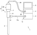
- an endoscope system 1 is configured to be inserted into a subject and to image a subject such as a living tissue in the subject and output it as an imaging signal.
- a light source device 3 configured to supply illumination light for illuminating the subject to the endoscope 2 and observation by performing signal processing on an imaging signal output from the endoscope 2
- the video processor 4 is configured to generate and output an image and the like
- the monitor 5 is configured to display an observation image output from the video processor 4 on a screen.
- FIG. 1 is a diagram illustrating a configuration of a main part of an endoscope system including a diagnosis support apparatus according to an embodiment.
- the endoscope 2 includes an optical viewing tube 2A having an elongated insertion portion 6 and a camera unit 2B that can be attached to and detached from the eyepiece 7 of the optical viewing tube 2A.
- the optical viewing tube 2A includes an elongated insertion portion 6 to be inserted into a subject, a gripping portion 8 provided at the proximal end portion of the insertion portion 6, and an eyepiece portion provided at the proximal end portion of the gripping portion 8. 7.
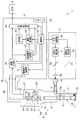
- FIG. 2 is a diagram for explaining an example of the internal configuration of the endoscope system of FIG. 1.
- the exit end of the light guide 11 is disposed in the vicinity of the illumination lens 15 at the distal end of the insertion section 6 as shown in FIG. Further, the incident end portion of the light guide 11 is disposed in a light guide base 12 provided in the grip portion 8.
- a light guide 13 for transmitting illumination light supplied from the light source device 3 is inserted into the cable 13a as shown in FIG.
- a connection member (not shown) that can be attached to and detached from the light guide base 12 is provided at one end of the cable 13a.
- a light guide connector 14 that can be attached to and detached from the light source device 3 is provided at the other end of the cable 13a.
- An illumination window in which an illumination lens 15 for emitting illumination light transmitted by the light guide 11 to the outside is disposed on the distal end surface of the insertion portion 6 and an optical according to light incident from the outside.
- An objective window in which an objective lens 17 for obtaining an image is arranged is provided adjacent to each other.
- a relay lens 18 for transmitting an optical image obtained by the objective lens 17 to the eyepiece unit 7 is provided inside the insertion unit 6.
- an eyepiece lens 19 is provided inside the eyepiece unit 7 so that the optical image transmitted by the relay lens 18 can be observed with the naked eye.
- the camera unit 2B includes a fluorescence imaging system that captures fluorescence as return light incident through the eyepiece lens 19 in the fluorescence observation mode and generates a fluorescence image, and a return incident through the eyepiece lens 19 in the white light observation mode.
- a white light imaging system that captures reflected light of white light as light and generates a white light image.
- the fluorescence imaging system and the white light imaging system are divided into two optical axes orthogonal to each other by a dichroic prism 21 having spectral characteristics that reflect white light and transmit fluorescence.
- the camera unit 2B includes a signal cable 28 provided with an end portion of a signal connector 29 that can be attached to and detached from the video processor 4.
- the fluorescence imaging system of the camera unit 2B has passed through the excitation light cut filter 22 having spectral characteristics that cut the wavelength band EW of the excitation light emitted from the light source device 3, the dichroic prism 21, and the excitation light cut filter 22.
- An imaging optical system 23 that forms an image of fluorescence and an image sensor 24 that images the fluorescence imaged by the imaging optical system 23 are provided.
- the image sensor 24 is constituted by, for example, a highly sensitive monochrome CCD. Further, the image sensor 24 is configured to perform an imaging operation according to an image sensor drive signal output from the video processor 4. The image sensor 24 is configured to capture the fluorescence imaged by the imaging optical system 23 and generate and output a fluorescence image corresponding to the captured fluorescence.
- the white light imaging system of the camera unit 2B includes an imaging optical system 25 that forms an image of white light reflected by the dichroic prism 21, an imaging element 26 that images the white light imaged by the imaging optical system 25, and It has.
- the image pickup element 26 is constituted by, for example, a color CCD having a primary color or complementary color filter provided on the image pickup surface. Further, the image sensor 26 is configured to perform an imaging operation according to an image sensor drive signal output from the video processor 4. The imaging element 26 is configured to capture the white light imaged by the imaging optical system 25 and generate and output a white light image corresponding to the captured white light.
- the camera unit 2B performs predetermined signal processing (correlated double sampling processing, gain adjustment processing, and A / D processing) on the fluorescence image output from the image sensor 24 and the white light image output from the image sensor 26.
- a signal processing circuit 27 configured to output the fluorescent image and the white light image subjected to the predetermined signal processing to the video processor 4 to which the signal cable 28 is connected.
- the light source device 3 includes a white light generation unit 31, an excitation light generation unit 32, dichroic mirrors 33 and 34, a condensing lens 35, and a light source control unit 36.
- the white light generator 31 includes, for example, a lamp or LED that emits broadband white light. Further, the white light generation unit 31 is configured to switch between a lighting state and a light-off state according to the control of the light source control unit 36. Further, the white light generation unit 31 is configured to generate white light having a light amount according to the control of the light source control unit 36.
- the excitation light generator 32 includes, for example, an LED that emits light (excitation light) in a predetermined wavelength band including the excitation wavelength of the fluorescent agent administered into the subject. Further, the excitation light generation unit 32 is configured to be switched to a lighting state or a light-off state according to the control of the light source control unit 36. In addition, the excitation light generation unit 32 is configured to generate excitation light having a light amount according to the control of the light source control unit 36.
- the dichroic mirror 33 is, for example, an optical device that transmits white light emitted from the white light generation unit 31 to the condenser lens 35 side and reflects excitation light emitted from the excitation light generation unit 32 to the condenser lens 35 side. It is formed with characteristics.
- the dichroic mirror 34 has, for example, an optical characteristic that reflects the excitation light emitted from the excitation light generation unit 32 to the dichroic mirror 33 side.
- the condensing lens 35 is configured to collect the light incident through the dichroic mirror 33 and emit it to the light guide 13.
- the light source control unit 36 is configured to control the white light generation unit 31 and the excitation light generation unit 32 in accordance with the illumination control signal output from the video processor 4.
- the video processor 4 includes an image sensor driving unit 41, an image input unit 42, a region identification processing unit 43, an arithmetic processing unit 44, a storage unit 45, an image processing unit 46, and an input I / F (interface) 52. And a control unit 53.
- the image sensor driving unit 41 includes, for example, a driver circuit.
- the image sensor drive unit 41 is configured to generate and output an image sensor drive signal according to the control of the control unit 53.
- the image input unit 42 includes, for example, a buffer memory and stores one frame of images sequentially output from the signal processing circuit 27 of the camera unit 2B, and stores the stored image one frame at a time to the control unit 53. It is configured to output.
- the image input unit 42 is configured to output the white light image accumulated in the white light observation mode to the image processing unit 46 frame by frame in accordance with the control of the control unit 53.
- the image input unit 42 is configured to output the fluorescence image accumulated in the fluorescence observation mode to the region identification processing unit 43 and the image processing unit 46 one frame at a time under the control of the control unit 53.
- the area identification processing unit 43 performs a labeling process on the fluorescent images sequentially output frame by frame from the image input unit 42 according to the control of the control unit 53, for example, so that the reference region included in the fluorescent image is included.
- Ar discussed below
- attention area Ai discussed below
- the arithmetic processing unit 44 includes, for example, an arithmetic processing circuit.
- the arithmetic processing unit 44 controls the luminance value of each pixel included in the reference region Ar of the fluorescent image sequentially output frame by frame from the region identification processing unit 43 according to the control of the control unit 53, and the fluorescent image. Based on the luminance value of each pixel included in the attention area Ai, an arithmetic processing for calculating an arithmetic value indicating the fluorescence intensity ratio of the attention area Ai with respect to the reference area Ar is performed.
- the arithmetic processing unit 44 is configured to output the arithmetic value obtained as a result of the arithmetic processing described above to the storage unit 45 and / or the image processing unit 46 under the control of the control unit 53.
- the storage unit 45 includes, for example, a memory and is configured to store a calculation value output from the calculation processing unit 44 with a time stamp.
- the image processing unit 46 includes, for example, an image processing circuit for performing predetermined image processing.
- the image processing unit 46 performs predetermined image processing on the white light image sequentially output frame by frame from the image input unit 42 in the white light observation mode in accordance with the control of the control unit 53 to thereby generate white light.
- An observation image is generated, and the generated white light observation image is output to the monitor 5.
- the image processing unit 46 performs a predetermined image processing on the fluorescence image sequentially output from the image input unit 42 for each frame in the fluorescence observation mode in accordance with the control of the control unit 53, thereby obtaining the fluorescence observation image.
- the generated fluorescence observation image is output to the monitor 5.
- the image processing unit 46 controls the fluorescent image output from the region identification processing unit 43, the calculation value output from the calculation processing unit 44, and the storage unit 45 in the fluorescence observation mode according to the control of the control unit 53.
- the monitor 5 is configured to perform processing for causing the monitor 5 to display diagnosis support information (described later) based on the calculated value read from.
- the input I / F 52 includes one or more input devices capable of giving instructions according to user operations. Specifically, the input I / F 52 gives an instruction to set (switch) the observation mode of the endoscope system 1 to either the white light observation mode or the fluorescence observation mode, for example, according to a user operation. And an observation mode changeover switch (not shown) that can be used. Also, the input I / F 52 is a diagnostic support information display switch (non-switchable) capable of setting (switching) the display of diagnostic support information in the fluorescence observation mode to either on or off according to the user's operation, for example. (Shown).
- a diagnostic support information display switch non-switchable
- the input I / F 52 can issue an instruction to set the reference area Ar and the attention area Ai in the fluorescence observation image displayed on the monitor 5 in the fluorescence observation mode, for example, according to the user's operation.
- a pointing device (not shown).
- the control unit 53 includes, for example, a CPU, and an illumination control signal for emitting illumination light corresponding to the observation mode of the endoscope system 1 based on an instruction given by the observation mode changeover switch of the input I / F 52. Is generated and output to the light source control unit 36. Further, the control unit 53 performs control for performing an operation according to the observation mode of the endoscope system 1 based on an instruction given by the observation mode changeover switch of the input I / F 52, the image sensor driving unit 41, and the image input.
- the unit 42 and the image processing unit 46 are configured so as to be performed.
- control unit 53 is performed in the pointing device of the input I / F 52 when the observation mode of the endoscope system 1 is set to the fluorescence observation mode and the display of the diagnosis support information is set to ON.
- the reference area Ar and the attention area Ai are respectively extracted from the fluorescence image output from the image input unit 42, and the generation state of the fluorescence of the attention area Ai with respect to the extracted reference area Ar is visualized.
- Control for displaying certain diagnosis support information on the monitor 5 is configured to be performed on the region identification processing unit 43, the arithmetic processing unit 44, and the image processing unit 46.
- a user such as an operator connects each part of the endoscope system 1 and turns on the power, and then operates the input I / F 52 to change the observation mode of the endoscope system 1 to the white light observation mode. Give instructions for setting.
- control unit 53 When the control unit 53 detects that the white light observation mode is set, the control unit 53 generates an illumination control signal for causing the light source device 3 to emit white light and outputs the illumination control signal to the light source control unit 36. Further, when detecting that the white light observation mode is set, the control unit 53 drives the image pickup device 26 of the camera unit 2B and controls the image pickup device 24 of the camera unit 2B to stop driving the image pickup device. To the unit 41.
- the light source control unit 36 performs control for turning on the white light generation unit 31 in accordance with the illumination control signal output from the control unit 53, and performs control for turning off the excitation light generation unit 32. Do.
- the image sensor drive unit 41 generates an image sensor drive signal for stopping the imaging operation and outputs the image sensor drive signal to the image sensor 24 according to the control of the control unit 53, and at a predetermined exposure period EA and a predetermined read period RA.
- An image sensor drive signal for performing the image capturing operation is generated and output to the image sensor 26.
- the light source control unit 36 and the image sensor driving unit 41 perform the operation as described above, so that the subject is irradiated with white light as illumination light, and the reflected light of the white light is captured by the image sensor 26.
- a white light image obtained by imaging the reflected light of the white light is output to the image input unit 42 via the signal processing circuit 27.
- the control unit 53 controls the image input unit 42 to output the white light images sequentially output from the camera unit 2B to the image processing unit 46 frame by frame. Against.
- the control unit 53 detects that the white light observation mode is set, the control unit 53 performs control for performing predetermined image processing on the white light image sequentially output from the image input unit 42 for each frame. This is performed on the image processing unit 46.
- control as described above is performed in the control unit 53, whereby the white light observation image is displayed on the monitor 5.
- the user places the distal end portion of the insertion portion 6 in the vicinity of a desired subject by inserting the insertion portion 6 into the subject while confirming the white light observation image displayed on the monitor 5. To do. Then, the user arranges the distal end portion of the insertion portion 6 in the vicinity of a desired subject, and then operates the input I / F 52 to instruct to set the observation mode of the endoscope system 1 to the fluorescence observation mode. I do.
- control unit 53 When the control unit 53 detects that the fluorescence observation mode is set, the control unit 53 generates an illumination control signal for emitting excitation light from the light source device 3 and outputs the illumination control signal to the light source control unit 36. Further, when detecting that the fluorescence observation mode is set, the control unit 53 drives the image pickup device 24 of the camera unit 2B and performs control to stop driving the image pickup device 26 of the camera unit 2B. 41.
- the light source control unit 36 performs control for turning off the white light generation unit 31 according to the illumination control signal output from the control unit 53, and performs control for turning on the excitation light generation unit 32. Do.
- the image sensor drive unit 41 generates an image sensor drive signal for stopping the imaging operation and outputs the image sensor drive signal to the image sensor 26 according to the control of the control unit 53, and in a predetermined exposure period EB and a predetermined readout period RB.
- An image sensor drive signal for performing an image capturing operation is generated and output to the image sensor 24.
- the operation as described above is performed in the light source control unit 36 and the image sensor driving unit 41, so that the excitation light is emitted as illumination light to the desired subject and emitted from the fluorescent agent excited by the excitation light.
- the captured fluorescence is imaged by the imaging device 24, and a fluorescence image obtained by imaging the fluorescence is output to the image input unit 42 via the signal processing circuit 27.
- control unit 53 When the control unit 53 detects that the fluorescence observation mode is set and the display of the diagnosis support information is turned off, the control unit 53 sequentially outputs the fluorescence images sequentially output from the camera unit 2B to the image processing unit 46 frame by frame. Control for outputting is performed on the image input unit 42. Further, when the control unit 53 detects that the fluorescence observation mode is set and the display of the diagnosis support information is set to off, the control unit 53 applies the fluorescence images sequentially output from the image input unit 42 for each frame. Control for performing predetermined image processing is performed on the image processing unit 46.
- control as described above is performed in the control unit 53, whereby the fluorescence observation image is displayed on the monitor 5.
- the user operates the input I / F 52 while confirming the fluorescence observation image displayed on the monitor 5 to give an instruction to switch the display setting of the diagnosis support information from off to on.
- control unit 53 When the control unit 53 detects that the display of the diagnosis support information is set to ON, the control unit 53 displays a character string or the like for prompting the setting of the reference area Ar and the attention area Ai in the fluorescence observation image together with the fluorescence observation image. Is controlled with respect to the image processing unit 46.
- the user operates the input I / F 52 while confirming the character string displayed on the monitor 5 together with the fluorescence observation image, thereby generating a fluorescence generation state from the fluorescence generation region included in the fluorescence observation image.
- An instruction for setting one reference area Ar treated as a reference and one or more attention areas Ai treated as comparison targets of the fluorescence generation state is issued.
- the reference area Ar and the attention area Ai in this embodiment are set as pixel areas each having one or more pixels.
- the control unit 53 having a function as a region extraction unit extracts the reference region Ar and the attention region Ai from the fluorescent image output from the image input unit 42 based on the instruction made in the input I / F 52. Process.
- FIG. 3 is a diagram illustrating an example of a fluorescence image used for processing of the diagnosis support apparatus according to the embodiment.
- FIG. 4 is a diagram illustrating an example in which the reference area Ar, the attention area Ai1, and the attention area Ai2 are extracted from the fluorescence image of FIG.
- the control unit 53 extracts the reference region Ar, the attention region Ai1, and the attention region Ai2 from the fluorescence image output from the image input unit 42, and then indicates the current fluorescence intensity ratio of the attention region Ai1 with respect to the reference region Ar.
- Control for displaying information and information indicating the current fluorescence intensity ratio of the attention area Ai2 with respect to the reference area Ar on the monitor 5 as diagnosis support information is performed by the area identification processing section 43, the arithmetic processing section 44, and the image processing section. 46.
- the area identification processing unit 43 performs a labeling process on the fluorescent images sequentially output frame by frame from the image input unit 42 in accordance with the control of the control unit 53, whereby the reference areas Ar, The attention areas Ai1 and Ai2 are made identifiable, and the fluorescent image subjected to the labeling process is output to the arithmetic processing unit 44.
- the arithmetic processing unit 44 represents the average value or the maximum value of the luminance values of the respective pixels in the reference region Ar included in the fluorescence image sequentially output frame by frame from the region identification processing unit 43 under the control of the control unit 53.
- An arithmetic value AV1 which is obtained as a value RV and is a ratio value obtained by dividing the luminance value of the attention area Ai1 included in the fluorescence image by the representative value RV is calculated for each pixel of the attention area Ai1.
- An arithmetic process is performed to calculate an arithmetic value AV2 that is a ratio value obtained by dividing the luminance value of the attention area Ai2 included in the image by the representative value RV for each pixel of the attention area Ai2.
- the arithmetic processing unit 44 outputs the arithmetic values AV1 and AV2 of each pixel obtained as a result of the above-described arithmetic processing to the storage unit 45 and the image processing unit 46, respectively.
- the image processing unit 46 selects a region identification processing unit 43 from among a plurality of color information determined in advance based on the magnitudes of the calculation values AV1 and AV2 output from the calculation processing unit 44. And processing for acquiring color information corresponding to each pixel of the attention areas Ai1 and Ai2 included in the fluorescence image sequentially output frame by frame, and using the acquired color information, Processing for outputting a diagnosis support image in which the areas Ai1 and Ai2 are colored to the monitor 5 is performed.
- FIG. 5 is a diagram illustrating an example of a diagnosis support image generated by the diagnosis support apparatus according to the embodiment.
- diagnosis support image of FIG. 5 for example, information indicating the current fluorescence intensity ratio of the attention area Ai1 with respect to the reference area Ar is displayed on the monitor 5 with the color C1, and the current of the attention area Ai2 with respect to the reference area Ar.
- Information indicating the fluorescence intensity ratio is displayed on the monitor 5 in color C2. That is, the diagnosis support image of FIG. 5 includes, as diagnosis support information, the color C1 that is the color information visualizing the current fluorescence intensity ratio of the attention area Ai1 with respect to the reference area Ar and the current of the attention area Ai2 with respect to the reference area Ar. And color C2, which is color information obtained by visualizing the fluorescence intensity ratio.
- the control unit 53 extracts the reference region Ar, the attention region Ai1, and the attention region Ai2 from the fluorescence image output from the image input unit 42, and then changes the fluorescence intensity ratio of the attention region Ai1 with respect to the reference region Ar over time. Control for causing the monitor 5 to display the time-dependent change in the fluorescence intensity ratio of the attention area Ai2 with respect to the reference area Ar as diagnosis support information for the area identification processing section 43, the arithmetic processing section 44, and the image processing section 46. Do.
- the area identification processing unit 43 performs a labeling process on the fluorescent images sequentially output frame by frame from the image input unit 42 in accordance with the control of the control unit 53, whereby the reference areas Ar, The attention areas Ai1 and Ai2 are made identifiable, and the fluorescent image subjected to the labeling process is output to the arithmetic processing unit 44.
- the arithmetic processing unit 44 represents the average value or the maximum value of the luminance values of the respective pixels in the reference region Ar included in the fluorescence image sequentially output frame by frame from the region identification processing unit 43 under the control of the control unit 53.
- the value RV the average value or the maximum value of the luminance values of each pixel of the attention area Ai1 included in the fluorescent image is acquired as the representative value RV1
- the luminance value of each pixel of the attention area Ai2 included in the fluorescent image Is obtained as a representative value RV2
- the storage unit 45 performs processing for assigning and storing time stamps indicating the same time for the arithmetic values AV3 and AV4 input simultaneously from the arithmetic processing unit 44.
- the arithmetic values AV3 and AV4 obtained as the processing result of the arithmetic processing unit 44 are obtained immediately after the reference area Ar, the attention area Ai1, and the attention area Ai2 are set.
- Each frame is stored in the storage unit 45 starting from the time Tf corresponding to the time.
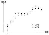
- the image processing unit 46 reads the arithmetic value AV3 stored in the storage unit 45 in time series, and uses a graph in which the read arithmetic value AV3 is arranged and plotted in time series as diagnosis support information. Processing for outputting to the monitor 5 is performed. Further, the image processing unit 46 reads the arithmetic value AV4 stored in the time series in the storage unit 45 according to the control of the control unit 53, and supports diagnosis of a graph in which the read arithmetic value AV4 is plotted in time series. A process for outputting the information to the monitor 5 is performed.
- FIG. 6 is a diagram illustrating an example of diagnosis support information generated by the diagnosis support apparatus according to the embodiment.
- the temporal change of the calculated value AV3 starting from the time Tf is displayed on the monitor 5 as a plurality of black points, and the temporal change of the calculated value AV4 starting from the time Tf. Are displayed on the monitor 5 as a plurality of white dots.
- the temporal change rate of the calculated values AV3 and AV4 is not limited to being displayed as the diagnosis support information, but for example, the temporal change rate of the calculated values AV3 and AV4 is displayed as the diagnostic support information. It may be.
- processing for displaying as information may be performed.
- the control unit 53 extracts the reference region Ar, the attention region Ai1, and the attention region Ai2 from the fluorescence image output from the image input unit 42, and then extracts one of the extracted attention region Ai1 or attention region Ai2.
- the image processing unit 46 is controlled to display a character string or the like that prompts selection of the pixel position together with the fluorescence observation image.
- the user operates the input I / F 52 while confirming the character string displayed on the monitor 5 together with the fluorescence observation image, so that one attention pixel is selected from the reference area Ar, the attention area Ai1, and the attention area Ai2.
- An instruction for selecting a PT is given.
- the control unit 53 specifies the target pixel PT from the fluorescent image output from the image input unit 42 based on the instruction made at the input I / F 52, and at the same time, the current fluorescence intensity of the target pixel PT with respect to the reference region Ar. Control for displaying the ratio value on the monitor 5 is performed on the region identification processing unit 43, the arithmetic processing unit 44, and the image processing unit 46.
- the area identification processing unit 43 performs a labeling process on the fluorescent images sequentially output frame by frame from the image input unit 42 in accordance with the control of the control unit 53, whereby the reference areas Ar, The attention areas Ai1 and Ai2 are made identifiable, and the fluorescent image subjected to the labeling process is output to the arithmetic processing unit 44.
- the image processing unit 46 performs processing for outputting the arithmetic value AV5 output from the arithmetic processing unit 44 to the monitor 5 as diagnosis support information in accordance with the control of the control unit 53.
- the current calculation value AV5 in the target pixel PT selected from the target regions Ai1 and Ai2 is displayed on the monitor 5 as diagnosis support information.
- processing for displaying a predetermined character string or the like for notification on the monitor 5 may be performed.
- the processing is not limited to the processing described above.
- the arithmetic value AV1 changes over time and is predetermined.
- Processing for causing the monitor 5 to blink and display the pixel group that has reached the value TH2 and the pixel group that has reached the predetermined value TH2 as the arithmetic value AV2 has changed over time may be performed.
- the processing is not limited to the processing described above.
- the calculation value AV3 and / or the calculation value AV4 changes with time and reaches the predetermined value TH3 at time Tg.
- a process for displaying the time required from the time Tf to Tg on the monitor 5 may be performed.
- the reference phosphor having known fluorescence characteristics with respect to the excitation light emitted from the light source device 3 when the user operates the input I / F 52.
- An instruction for setting the area where the symbol is placed as the reference area Ar may be given.
- a calibration auxiliary means for fluorescence observation disclosed in Japanese Patent Laid-Open No. 2005-300540 may be used as the reference phosphor.
- a process of extracting the area where the reference phosphor is arranged as the reference area Ar may be performed.
- the operation of the endoscope system 1 when such processing is performed will be described below.
- FIG. 7 is a diagram illustrating an example of a configuration of a fluorescent member used in combination with the diagnosis support apparatus according to the embodiment.
- the fluorescent member 101 is formed, for example, as a flat plate member having a rectangular shape in plan view as shown in FIG.
- the fluorescent member 101 may be formed to have another planar view shape such as a star shape, for example.
- the fluorescent member 101 is provided so as to surround the reference phosphor 102 having known fluorescence characteristics with respect to the excitation light emitted from the light source device 3 and the outer edge of the reference phosphor 102.
- the frame member 103 is formed.
- the reference phosphor 102 is formed, for example, by covering the surface of a phosphor such as a quantum dot with glass.
- the frame member 103 is formed using a non-fluorescent member that does not generate fluorescence according to excitation light emitted from the light source device 3, such as black PEEK (polyether ether ketone) resin.
- a non-fluorescent member that does not generate fluorescence according to excitation light emitted from the light source device 3, such as black PEEK (polyether ether ketone) resin.
- FIG. 8 is a diagram illustrating an example of a fluorescent image captured in a state where the fluorescent member of FIG. 7 is arranged.
- the control unit 53 detects that the display of the diagnosis support information is turned on, the reference phosphor 102 exists in the inner region surrounded by the frame member 103 based on the fluorescence image output from the image input unit 42. And a process of extracting the specified area as the reference area Ar.
- control unit 53 generates an edge image by performing edge extraction processing on the fluorescent image output from the image input unit 42, and performs Hough transform on the generated edge image.
- a straight line shape is extracted, an internal region surrounded by the extracted straight line shape is specified as a region where the reference phosphor 102 exists, and the specified region is extracted as a reference region Ar.
- the present embodiment it is possible to display on the monitor 5 diagnosis support information that visualizes the fluorescence generation state of one or more attention areas Ai with respect to one reference area Ar. As a result, according to the present embodiment, it is possible to reduce the burden on the operator who makes a diagnosis by fluorescence observation using an endoscope.
- diagnosis support information may be displayed on the monitor 5, or a plurality of diagnosis support information may be displayed on the monitor 5 at the same time.
- diagnosis support information may be superimposed on the fluorescence observation image and displayed on the monitor 5, and may be displayed in a display area different from the display area of the fluorescence observation image on the monitor 5.
- Diagnosis support information or diagnosis support images may be displayed.
Landscapes
- Health & Medical Sciences (AREA)
- Life Sciences & Earth Sciences (AREA)
- Surgery (AREA)
- Physics & Mathematics (AREA)
- Engineering & Computer Science (AREA)
- Optics & Photonics (AREA)
- General Health & Medical Sciences (AREA)
- Medical Informatics (AREA)
- Biomedical Technology (AREA)
- Veterinary Medicine (AREA)
- Nuclear Medicine, Radiotherapy & Molecular Imaging (AREA)
- Pathology (AREA)
- Radiology & Medical Imaging (AREA)
- Biophysics (AREA)
- Public Health (AREA)
- Heart & Thoracic Surgery (AREA)
- Animal Behavior & Ethology (AREA)
- Molecular Biology (AREA)
- General Physics & Mathematics (AREA)
- Signal Processing (AREA)
- Multimedia (AREA)
- Astronomy & Astrophysics (AREA)
- Quality & Reliability (AREA)
- Computer Vision & Pattern Recognition (AREA)
- Theoretical Computer Science (AREA)
- Endoscopes (AREA)
- Instruments For Viewing The Inside Of Hollow Bodies (AREA)
- Closed-Circuit Television Systems (AREA)
Abstract
Priority Applications (4)
| Application Number | Priority Date | Filing Date | Title |
|---|---|---|---|
| EP15862891.7A EP3141178A4 (fr) | 2014-11-26 | 2015-10-14 | Dispositif d'aide au diagnostic et procédé d'affichage d'informations d'aide au diagnostic |
| CN201580032472.8A CN106659360A (zh) | 2014-11-26 | 2015-10-14 | 诊断支援装置和诊断支援信息显示方法 |
| JP2016538152A JP6013665B1 (ja) | 2014-11-26 | 2015-10-14 | 診断支援装置及び診断支援情報表示方法 |
| US15/371,831 US20170086659A1 (en) | 2014-11-26 | 2016-12-07 | Diagnosis assisting apparatus and diagnosis assisting information display method |
Applications Claiming Priority (2)
| Application Number | Priority Date | Filing Date | Title |
|---|---|---|---|
| JP2014239157 | 2014-11-26 | ||
| JP2014-239157 | 2014-11-26 |
Related Child Applications (1)
| Application Number | Title | Priority Date | Filing Date |
|---|---|---|---|
| US15/371,831 Continuation US20170086659A1 (en) | 2014-11-26 | 2016-12-07 | Diagnosis assisting apparatus and diagnosis assisting information display method |
Publications (1)
| Publication Number | Publication Date |
|---|---|
| WO2016084504A1 true WO2016084504A1 (fr) | 2016-06-02 |
Family
ID=56074082
Family Applications (1)
| Application Number | Title | Priority Date | Filing Date |
|---|---|---|---|
| PCT/JP2015/078992 WO2016084504A1 (fr) | 2014-11-26 | 2015-10-14 | Dispositif d'aide au diagnostic et procédé d'affichage d'informations d'aide au diagnostic |
Country Status (5)
| Country | Link |
|---|---|
| US (1) | US20170086659A1 (fr) |
| EP (1) | EP3141178A4 (fr) |
| JP (1) | JP6013665B1 (fr) |
| CN (1) | CN106659360A (fr) |
| WO (1) | WO2016084504A1 (fr) |
Cited By (3)
| Publication number | Priority date | Publication date | Assignee | Title |
|---|---|---|---|---|
| WO2018198161A1 (fr) * | 2017-04-24 | 2018-11-01 | オリンパス株式会社 | Appareil de traitement d'images d'endoscope et procédé de traitement d'images d'endoscope |
| WO2018203383A1 (fr) * | 2017-05-02 | 2018-11-08 | オリンパス株式会社 | Dispositif de traitement d'image et programme de traitement d'image |
| US12053161B2 (en) | 2019-02-26 | 2024-08-06 | Olympus Corporation | Endoscope apparatus, information storage medium, control method of endoscope apparatus, and processing device |
Families Citing this family (6)
| Publication number | Priority date | Publication date | Assignee | Title |
|---|---|---|---|---|
| EP3841954A4 (fr) * | 2018-08-20 | 2021-10-13 | FUJIFILM Corporation | Système de traitement d'image médicale |
| WO2020066941A1 (fr) * | 2018-09-26 | 2020-04-02 | 富士フイルム株式会社 | Dispositif de traitement d'image médicale, système d'endoscope, et procédé de fonctionnement de dispositif de traitement d'image médicale |
| JP7017646B2 (ja) * | 2018-10-26 | 2022-02-08 | オリンパス株式会社 | 内視鏡用画像処理装置、及び、内視鏡用画像処理装置の作動方法、並びに、内視鏡用画像処理プログラム |
| JP6921886B2 (ja) * | 2019-03-19 | 2021-08-18 | キヤノン株式会社 | 情報処理装置および情報処理方法 |
| JP7451170B2 (ja) * | 2019-12-20 | 2024-03-18 | エヌ・ティ・ティ・コミュニケーションズ株式会社 | 情報処理装置、情報処理方法およびプログラム |
| EP4213712A4 (fr) * | 2020-09-18 | 2024-07-31 | Stryker European Operations Ltd | Systèmes et procédés de visualisation de fluorescence |
Citations (4)
| Publication number | Priority date | Publication date | Assignee | Title |
|---|---|---|---|---|
| JPH06503979A (ja) * | 1991-01-04 | 1994-05-12 | アンスチチュ ナショナル ド ラ サント エ ド ラ ルシェルシュ メディカル−アンセルム | 標的のpHを測定する装置、該装置の使用方法及びその用途 |
| JP2005040181A (ja) * | 2003-07-23 | 2005-02-17 | Pentax Corp | 自家蛍光観察装置 |
| JP2008154846A (ja) * | 2006-12-25 | 2008-07-10 | Olympus Corp | 蛍光内視鏡および蛍光測定方法 |
| JP2011194164A (ja) * | 2010-03-23 | 2011-10-06 | Olympus Corp | 蛍光観察装置 |
Family Cites Families (20)
| Publication number | Priority date | Publication date | Assignee | Title |
|---|---|---|---|---|
| JP2001137173A (ja) * | 1999-11-11 | 2001-05-22 | Fuji Photo Film Co Ltd | 蛍光画像測定方法および装置 |
| JP2004024932A (ja) * | 2002-06-21 | 2004-01-29 | Nok Corp | 中空糸膜モジュール |
| WO2006065739A2 (fr) * | 2004-12-14 | 2006-06-22 | Millennium Pharmaceuticals, Inc | Dispositif permettant d'agreger, d'imager et d'analyser des thrombi, et procede d'utilisation associe |
| US20090234187A1 (en) * | 2006-10-13 | 2009-09-17 | Olympus Corporation | Method of microscopic observation of an inside of a body of a small animal |
| JP2009201940A (ja) * | 2008-02-29 | 2009-09-10 | Hoya Corp | 内視鏡光源システム、内視鏡光源装置、内視鏡プロセッサ、および内視鏡ユニット |
| WO2010116552A1 (fr) * | 2009-03-30 | 2010-10-14 | オリンパスメディカルシステムズ株式会社 | Dispositif d'observation de fluorescence |
| JP5356191B2 (ja) * | 2009-11-26 | 2013-12-04 | オリンパス株式会社 | 蛍光観察装置 |
| JP5555002B2 (ja) * | 2010-02-10 | 2014-07-23 | オリンパス株式会社 | 蛍光内視鏡装置 |
| JP5622461B2 (ja) * | 2010-07-07 | 2014-11-12 | オリンパス株式会社 | 画像処理装置、画像処理方法、および画像処理プログラム |
| EP2679136B1 (fr) * | 2011-02-21 | 2016-01-20 | Olympus Corporation | Dispositif d'observation à fluorescence |
| JP6006199B2 (ja) * | 2011-03-31 | 2016-10-12 | オリンパス株式会社 | 蛍光観察装置 |
| EP2735257A4 (fr) * | 2011-07-22 | 2015-05-27 | Olympus Corp | Système d'endoscopie à fluorescence |
| JP5750381B2 (ja) * | 2012-02-13 | 2015-07-22 | 株式会社日立製作所 | 領域抽出処理システム |
| JP5979904B2 (ja) * | 2012-02-20 | 2016-08-31 | キヤノン株式会社 | 画像処理装置、眼科撮影システム、及び画像処理方法 |
| JP6046111B2 (ja) * | 2012-03-01 | 2016-12-14 | 株式会社日立製作所 | 医用画像表示装置、及び医用画像表示方法 |
| JP6116561B2 (ja) * | 2012-06-15 | 2017-04-19 | オリンパス株式会社 | 画像処理装置、顕微鏡システム及び画像処理方法 |
| JP5993237B2 (ja) * | 2012-07-25 | 2016-09-14 | オリンパス株式会社 | 蛍光観察装置 |
| CN104114077B (zh) * | 2012-10-18 | 2016-07-20 | 奥林巴斯株式会社 | 图像处理装置和图像处理方法 |
| WO2014207904A1 (fr) * | 2013-06-28 | 2014-12-31 | キヤノン株式会社 | Dispositif de traitement d'image et procédé de traitement d'image |
| JP6030035B2 (ja) * | 2013-09-27 | 2016-11-24 | 富士フイルム株式会社 | 蛍光観察装置、内視鏡システム及びプロセッサ装置並びに作動方法 |
-
2015
- 2015-10-14 CN CN201580032472.8A patent/CN106659360A/zh active Pending
- 2015-10-14 WO PCT/JP2015/078992 patent/WO2016084504A1/fr active Application Filing
- 2015-10-14 JP JP2016538152A patent/JP6013665B1/ja active Active
- 2015-10-14 EP EP15862891.7A patent/EP3141178A4/fr not_active Withdrawn
-
2016
- 2016-12-07 US US15/371,831 patent/US20170086659A1/en not_active Abandoned
Patent Citations (4)
| Publication number | Priority date | Publication date | Assignee | Title |
|---|---|---|---|---|
| JPH06503979A (ja) * | 1991-01-04 | 1994-05-12 | アンスチチュ ナショナル ド ラ サント エ ド ラ ルシェルシュ メディカル−アンセルム | 標的のpHを測定する装置、該装置の使用方法及びその用途 |
| JP2005040181A (ja) * | 2003-07-23 | 2005-02-17 | Pentax Corp | 自家蛍光観察装置 |
| JP2008154846A (ja) * | 2006-12-25 | 2008-07-10 | Olympus Corp | 蛍光内視鏡および蛍光測定方法 |
| JP2011194164A (ja) * | 2010-03-23 | 2011-10-06 | Olympus Corp | 蛍光観察装置 |
Non-Patent Citations (1)
| Title |
|---|
| See also references of EP3141178A4 * |
Cited By (4)
| Publication number | Priority date | Publication date | Assignee | Title |
|---|---|---|---|---|
| WO2018198161A1 (fr) * | 2017-04-24 | 2018-11-01 | オリンパス株式会社 | Appareil de traitement d'images d'endoscope et procédé de traitement d'images d'endoscope |
| US11176665B2 (en) | 2017-04-24 | 2021-11-16 | Olympus Corporation | Endoscopic image processing device and endoscopic image processing method |
| WO2018203383A1 (fr) * | 2017-05-02 | 2018-11-08 | オリンパス株式会社 | Dispositif de traitement d'image et programme de traitement d'image |
| US12053161B2 (en) | 2019-02-26 | 2024-08-06 | Olympus Corporation | Endoscope apparatus, information storage medium, control method of endoscope apparatus, and processing device |
Also Published As
| Publication number | Publication date |
|---|---|
| EP3141178A4 (fr) | 2018-02-21 |
| CN106659360A (zh) | 2017-05-10 |
| EP3141178A1 (fr) | 2017-03-15 |
| JP6013665B1 (ja) | 2016-10-25 |
| JPWO2016084504A1 (ja) | 2017-04-27 |
| US20170086659A1 (en) | 2017-03-30 |
Similar Documents
| Publication | Publication Date | Title |
|---|---|---|
| JP6013665B1 (ja) | 診断支援装置及び診断支援情報表示方法 | |
| JP6435275B2 (ja) | 内視鏡装置 | |
| US9392942B2 (en) | Fluoroscopy apparatus and fluoroscopy system | |
| EP3085300A1 (fr) | Dispositif d'endoscope | |
| JP6001219B1 (ja) | 内視鏡システム | |
| US9414739B2 (en) | Imaging apparatus for controlling fluorescence imaging in divided imaging surface | |
| JP5769892B2 (ja) | 内視鏡 | |
| WO2018047369A1 (fr) | Système d'endoscope | |
| EP3085299A1 (fr) | Dispositif endoscopique | |
| WO2017115442A1 (fr) | Appareil de traitement d'image, procédé de traitement d'image et programme de traitement d'image | |
| WO2019123827A1 (fr) | Système endoscope et processeur d'endoscope | |
| WO2017104192A1 (fr) | Système d'observation médicale | |
| CN114945314A (zh) | 医疗图像处理装置、内窥镜系统、诊断辅助方法及程序 | |
| JP2011005002A (ja) | 内視鏡装置 | |
| WO2016088628A1 (fr) | Dispositif d'évaluation d'image, système d'endoscope, procédé et programme de commande d'un dispositif d'évaluation d'image | |
| JP2002345739A (ja) | 画像表示装置 | |
| JP6137892B2 (ja) | 撮像システム | |
| JP2005204958A (ja) | 自家蛍光観察可能な電子内視鏡装置およびシステム | |
| JP5815162B2 (ja) | 撮像装置 | |
| JP6205531B1 (ja) | 内視鏡システム | |
| JP6266559B2 (ja) | 内視鏡診断装置、画像処理方法、プログラムおよび記録媒体 | |
| JP7029281B2 (ja) | 内視鏡システム及び内視鏡システムの作動方法 | |
| JP6120758B2 (ja) | 医用システム | |
| WO2016072172A1 (fr) | Système d'endoscope | |
| WO2022208629A1 (fr) | Dispositif d'observation de fluorescence, système de photo-immunothérapie et endoscope à fluorescence |
Legal Events
| Date | Code | Title | Description |
|---|---|---|---|
| ENP | Entry into the national phase |
Ref document number: 2016538152 Country of ref document: JP Kind code of ref document: A |
|
| 121 | Ep: the epo has been informed by wipo that ep was designated in this application |
Ref document number: 15862891 Country of ref document: EP Kind code of ref document: A1 |
|
| REEP | Request for entry into the european phase |
Ref document number: 2015862891 Country of ref document: EP |
|
| WWE | Wipo information: entry into national phase |
Ref document number: 2015862891 Country of ref document: EP |
|
| NENP | Non-entry into the national phase |
Ref country code: DE |