WO2016084342A1 - 導電性ペースト及びそれを用いてなる熱電対 - Google Patents
導電性ペースト及びそれを用いてなる熱電対 Download PDFInfo
- Publication number
- WO2016084342A1 WO2016084342A1 PCT/JP2015/005737 JP2015005737W WO2016084342A1 WO 2016084342 A1 WO2016084342 A1 WO 2016084342A1 JP 2015005737 W JP2015005737 W JP 2015005737W WO 2016084342 A1 WO2016084342 A1 WO 2016084342A1
- Authority
- WO
- WIPO (PCT)
- Prior art keywords
- conductive paste
- copper
- thermocouple
- powder
- paste
- Prior art date
- Legal status (The legal status is an assumption and is not a legal conclusion. Google has not performed a legal analysis and makes no representation as to the accuracy of the status listed.)
- Ceased
Links
Images



Classifications
-
- G—PHYSICS
- G01—MEASURING; TESTING
- G01K—MEASURING TEMPERATURE; MEASURING QUANTITY OF HEAT; THERMALLY-SENSITIVE ELEMENTS NOT OTHERWISE PROVIDED FOR
- G01K7/00—Measuring temperature based on the use of electric or magnetic elements directly sensitive to heat ; Power supply therefor, e.g. using thermoelectric elements
- G01K7/02—Measuring temperature based on the use of electric or magnetic elements directly sensitive to heat ; Power supply therefor, e.g. using thermoelectric elements using thermoelectric elements, e.g. thermocouples
-
- H—ELECTRICITY
- H01—ELECTRIC ELEMENTS
- H01B—CABLES; CONDUCTORS; INSULATORS; SELECTION OF MATERIALS FOR THEIR CONDUCTIVE, INSULATING OR DIELECTRIC PROPERTIES
- H01B1/00—Conductors or conductive bodies characterised by the conductive materials; Selection of materials as conductors
- H01B1/02—Conductors or conductive bodies characterised by the conductive materials; Selection of materials as conductors mainly consisting of metals or alloys
- H01B1/026—Alloys based on copper
-
- H—ELECTRICITY
- H01—ELECTRIC ELEMENTS
- H01B—CABLES; CONDUCTORS; INSULATORS; SELECTION OF MATERIALS FOR THEIR CONDUCTIVE, INSULATING OR DIELECTRIC PROPERTIES
- H01B1/00—Conductors or conductive bodies characterised by the conductive materials; Selection of materials as conductors
- H01B1/20—Conductive material dispersed in non-conductive organic material
- H01B1/22—Conductive material dispersed in non-conductive organic material the conductive material comprising metals or alloys
Definitions
- the present invention relates to a conductive paste and a thermocouple using the same.
- Conductive paste consisting of metal powder and binder component is widely used for various purposes such as hole filling of substrate, conductive adhesive, electrode formation, component mounting, electromagnetic wave shield, conductive bump formation, etc. Is generally based on an epoxy resin.
- the present inventors have proposed a conductive paste containing a (meth) acrylate compound and an epoxy resin as a conductive paste suitable for hole filling and the like and containing a phenolic curing agent or the like at a predetermined ratio. (Patent Document 1).
- thermocouples using conductive paste are also being manufactured.
- thermocouples are formed in various shapes by combining various metals according to their applications.
- Patent Document 2 discloses a resin film having flexibility including a paste containing copper powder and a paste containing constantan powder.
- a thermocouple capable of measuring the temperature of a minute portion is formed by printing on a paper and peeling off the paper.
- thermocouple manufactured using such a conductive paste it can be applied not only to industrial use but also to various uses such as medical use and home use. The nature is expected to expand greatly.
- the conductive paste tends to decrease in conductivity as the flexibility of the binder resin increases, and a conductive paste suitable for manufacturing a flexible thermocouple has not yet been obtained.
- the present invention has been made in view of the above, and an object thereof is to provide a conductive paste excellent in both flexibility and conductivity and a thermocouple excellent in flexibility using the same.
- the conductive paste of the present invention contains (a) a metal powder, (b) a binder component containing alkylene glycol diglycidyl ether, and (c) a curing agent. .
- the binder component (b) contains 5% by mass or more of one or two selected from ethylene glycol diglycidyl ether and propylene glycol diglycidyl ether as alkylene glycol diglycidyl ether. Can do. Moreover, copper powder and constantan powder can be used as the metal powder.
- thermocouple of the present invention may be formed by connecting a conductive paste using the above constantan powder and a copper wiring. Or the wiring which consists of an electroconductive paste using the said constantan powder, and the wiring which consists of an electroconductive paste using copper powder shall be connected.
- a surface temperature measuring device can be obtained by arranging two or more thermocouples of the present invention in the surface direction of a sheet-like material.
- the conductive paste of the present invention has flexibility and conductivity by using an alkylene glycol diglycidyl ether such as ethylene glycol diglycidyl ether and propylene glycol diglycidyl ether as a binder component as described above. Become.
- thermocouple of the present invention is excellent in flexibility by using this conductive paste, it can be used for various new applications.
- the surface temperature measuring device is constituted by the thermocouple of the present invention as described above, it becomes possible to measure the temperature distribution on the curved surface or the surface with irregularities more accurately than in the past.
- thermocouple which concerns on embodiment of this invention
- (a) shows the example of the thermocouple formed using the copper pattern (copper wiring) and the electrically conductive paste
- thermocouple formed using two kinds of conductive pastes each containing metal powder for example, constantan powder and copper powder
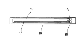
- FIG.1 shows the more concrete embodiment of the thermocouple shown in FIG.1 (b).
- FIG.1 shows the more concrete embodiment of the thermocouple shown in FIG.1 (b).
- FIG.1 shows the more concrete embodiment of the thermocouple shown in FIG.1 (b).
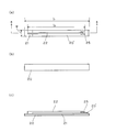
- (a) is a top view which shows the surface of the thermocouple formed using copper foil and a constantan powder containing paste
- FIG. 2 is a plan view showing the back surface of the same thermocouple
- FIG. 2C is a schematic cross-sectional view taken along aa of the same thermocouple.
- A) is a top view which shows the example of the surface temperature measuring apparatus which concerns on embodiment of this invention
- (b) is a top view which shows the example of the thermocouple which comprises the surface temperature measuring apparatus.
- (A) is a schematic cross-sectional view showing a substrate that can be used for manufacturing the surface temperature measuring device shown in FIG. 4, and
- (b) is a schematic cross-sectional view taken along line AA of the thermocouple shown in FIG. 4 (b).
- It is a figure and (c) is a schematic cross section which shows the thermocouple which concerns on other embodiment. It is a schematic diagram which shows the measuring method of the thermoelectromotive force of a thermocouple.
- the present invention is not limited to the following description.
- the conductive paste after curing may also be referred to as “conductive paste” for convenience.
- the electrically conductive paste of this invention is suitable for manufacture of a thermocouple, a use is not limited to this.
- the metal powder that can be contained in the conductive paste of the present invention is not particularly limited, but is preferably copper powder and / or copper alloy powder from the viewpoint of being suitable for the production of thermocouples.
- Constantan is preferably used as the copper alloy.
- Constantan has a composition of 55 ⁇ 5% copper and 45 ⁇ 5% Ni, typically 55% copper and 45% Ni.
- a thermocouple can be used in a temperature range of ⁇ 200 ° C. to 300 ° C. by using copper for the positive electrode and constantan for the negative electrode.
- the conductive paste of the present invention is assumed to be printed on a printed circuit board such as polyimide, and the metal powder in the case of constituting a thermocouple is -200 to 300 in consideration of heat resistance of the printed circuit board and the like.
- a combination of copper and constantan that can measure at relatively low temperatures of about 0 ° C is compatible.
- the shape of the metal powder is not limited, and conventionally used ones such as a dendritic shape, a spherical shape, and a flake shape (scale shape) can be used, but a dendritic shape is preferable from the viewpoint of conductivity.
- the particle size of the metal powder is not limited, but usually the average particle size is preferably about 1 to 50 ⁇ m.
- the binder component constituting the conductive paste of the present invention contains at least alkylene glycol diglycidyl ether, and the inclusion thereof can impart flexibility to the conductive paste.
- alkylene glycol diglycidyl ether include ethylene glycol diglycidyl ether and propylene glycol diglycidyl ether, which will be described below.
- polyethylene glycol diglycidyl ether and propylene glycol diglycidyl ether preferably have an ethylene oxide or propylene oxide unit repeating number n in the range of 1 to 15, preferably in the range of 4 to 10. More preferably.
- the content of alkylene glycol diglycidyl ether is preferably 5% by mass or more, more preferably 10 to 80% by mass in the binder component.
- Polyethylene glycol diglycidyl ether and propylene glycol diglycidyl ether can be produced by known methods, and commercially available products can also be used.
- the binder component used in the present invention may contain an epoxy resin other than the alkylene glycol diglycidyl ether or a (meth) acrylate compound as necessary.
- the epoxy resin is not particularly limited as long as it has one or more epoxy groups in the molecule.
- Examples include bisphenol A type epoxy resins, bisphenol F type epoxy resins, bisphenol S type epoxy resins, bisphenol type epoxy resins, spirocyclic epoxy resins, naphthalene type epoxy resins, biphenyl type epoxy resins, terpene type epoxy resins, tris Glycidyl ether type epoxy resins such as (glycidyloxyphenyl) methane and tetrakis (glycidyloxyphenyl) ethane, glycidylamine type epoxy resins such as tetraglycidyldiaminodiphenylmethane, tetrabromobisphenol A type epoxy resin, cresol novolac type epoxy resin, phenol novolac Type epoxy resin, ⁇ -naphthol novolac type epoxy resin, brominated phenol novolac type epoxy resin, etc. novolac type epoxy Fat, rubber-mod
- the content thereof is preferably 5 to 95% by mass, more preferably 20 to 90% by mass in the binder component.
- the (meth) acrylate compound is an acrylate compound or a methacrylate compound, and is not particularly limited as long as it is a compound having an acryloyl group or a methacryloyl group.
- Examples of (meth) acrylate compounds include isoamyl acrylate, neopentyl glycol diacrylate, trimethylolpropane triacrylate, ditrimethylolpropane tetraacrylate, 2-hydroxy-3-acryloyloxypropyl methacrylate, phenylglycidyl ether acrylate hexamethylene diisocyanate.
- Examples include urethane prepolymers, bisphenol A diglycidyl ether acrylic acid adducts, ethylene glycol dimethacrylate, and diethylene glycol dimethacrylate. These can also contain 1 type independently and can also contain 2 or more types.
- the content ratio of the epoxy resin and the (meth) acrylate compound (% by mass when the total amount of both is 100%) is 5:95 to 95: 5. And more preferably 20:80 to 80:20.
- the storage stability of the conductive paste is excellent, and the conductive paste can be quickly cured.
- the binder component contained in the conductive paste of the present invention can contain an alkyd resin, a melamine resin, a xylene resin or the like as a modifier in addition to the epoxy resin or the (meth) acrylate compound.
- the content ratio of the metal powder and the binder component is such that the content of the metal powder is 200 to 1800 mass with respect to 100 mass parts of the binder component from the viewpoint of the balance of flexibility, conductivity and printing workability (viscosity). Part is preferable, and 400 to 1200 parts by mass is more preferable.
- the conductive paste of the present invention may contain a curing agent.
- the curing agent is appropriately selected according to the type of binder component to be contained, and examples include a phenolic curing agent, an imidazole curing agent, a cationic curing agent, and a radical curing agent (polymerization initiator). It is done. These hardening
- curing agents can also be contained independently and can also contain 2 or more types.
- phenolic curing agents include novolak phenol and naphtholic compounds.
- the binder component contains a (meth) acrylate compound and a phenolic curing agent is included as a curing agent
- the added phenolic curing agent acts as a polymerization inhibitor for the (meth) acrylate compound. Pot life is improved compared to the case of 100%.
- this paste is heated, the epoxy resin first reacts with the phenolic curing agent, and then the curing proceeds due to the reaction with the (meth) acrylate compound that has lost the polymerization inhibitor.
- imidazole curing agents examples include imidazole, 2-undecylimidazole, 2-heptadecylimidazole, 2-ethylimidazole, 2-phenylimidazole, 2-ethyl-4-methyl-imidazole, 1-cyanoethyl-2-un. Examples include decylimidazole and 2-phenylimidazole.
- cationic curing agents include amine salts of boron trifluoride, P-methoxybenzenediazonium hexafluorophosphate, diphenyliodonium hexafluorophosphate, triphenylsulfonium, tetra-n-butylphosphonium tetraphenylborate, tetra- Examples thereof include onium compounds represented by n-butylphosphonium-o, o-diethyl phosphorodithioate and the like.
- radical curing agents examples include di-cumyl peroxide, t-butyl cumyl peroxide, t-butyl hydroperoxide, cumene hydroperoxide, and the like.
- the content of the curing agent is preferably 0.5 to 40 parts by mass with respect to 100 parts by mass of the total amount of binder components.
- the amount is preferably 0.1 to 5 parts by mass with respect to 100 parts by mass of the total amount of the binder components.
- the conductive paste of the present invention may contain known additives such as an antifoaming agent, a thickening agent, a pressure-sensitive adhesive, a filler, a flame retardant, and a colorant as long as the object of the invention is not impaired.
- thermocouple is a crack after a conductive paste is printed on a printed circuit board or the like and cured after being wound around a ⁇ 6 cm cylinder at room temperature for 5 seconds and released. This means that there is no generation or change in conductivity and there is no hindrance to temperature measurement as a thermocouple, and ⁇ flexible '' conductive paste refers to such a thermocouple when used as a binder.
- a conductive paste that can be formed shall be said.
- the conductive paste according to the present invention is suitably used for the production of a thermocouple described later, taking advantage of its excellent flexibility and conductivity, as well as conductive adhesive, electrode formation, component mounting, electromagnetic wave shielding, conductive It can also be used for forming a functional bump.
- thermocouple of the present invention has a cured product of the above-described conductive paste as a constituent element, and an embodiment thereof will be described below with reference to the drawings. However, the present invention is not limited to these.
- FIG. 1 (a) shows an example of a thermocouple made of a copper pattern and a conductive paste
- FIG. 1 (b) shows an example of a thermocouple made of two kinds of conductive pastes each containing different metal powders.
- reference numeral 1 is a copper pattern
- reference numerals 2 and 4 are constantan powder-containing conductive pastes
- reference numeral 3 is a copper powder-containing conductive paste
- reference numeral 5 is a copper pad (copper foil).
- thermocouple shown in FIG. 1 (a) has a copper-like copper pattern 1 and a copper pad 5 formed by etching or the like on a resin film made of, for example, polyimide or the like, and a conductive paste 2 containing constantan powder. It is printed in a straight line so that one end overlaps the copper pattern 1 and the other end overlaps the copper pad 5.
- the shape of the copper pattern and the copper pad, the printed shape of the conductive paste, and the like are not limited to those illustrated, and the manufacturing method is not limited to the above, and this is the same in the following embodiments.
- thermocouple shown in FIG. 1B, a copper pad 5 is provided by etching or the like on a resin film similar to the above, and the conductive paste 3 containing copper powder has an end on the copper pad 5.
- the conductive paste 4 which is printed in a bowl shape and contains constantan powder so as to be opposite to this is also printed in a bowl shape having an end on the copper pad 5, and the other end of the conductive paste 3, 4. Are overlapping each other.
- the conductive paste 4 containing constantan powder may be printed first, and the conductive paste 3 containing copper powder may be printed so that the end is covered with the end.
- thermocouples When comparing the above two types of thermocouples, the one shown in FIG. 1 (a) has the advantage of higher stability.
- thermocouple 10 denotes a polyimide film
- reference numeral 11 denotes a copper powder-containing conductive paste
- reference numeral 12 denotes a constantan powder-containing conductive paste
- reference numeral 15 denotes a copper pad.
- two copper pads 15 are provided side by side near the end of a long and narrow polyimide film 10 as a base, and two types of conductive pastes 11 and 12 are printed almost parallel to the longitudinal direction of the polyimide film 10.
- These two types of conductive pastes have a structure in which one end portion covers the copper pad 15 and the other end portion overlaps each other.
- the shape of each part can be appropriately changed depending on the use of the thermocouple.
- thermocouple of the present invention As another embodiment of the thermocouple of the present invention, as shown in FIGS. 3A to 3C, the constantane powder-containing conductive paste 22 printed on the polyimide film 20 and the copper foil 21 overlap each other. Also, a structure in which both of them are connected can be adopted. More specifically, as shown in FIGS. 3A and 3C, a rectangular polyimide film 20 having the same size is attached to the lower surface of the copper foil 21 having a rectangular planar shape, and laminated. A rectangular polyimide film 20 ′ having the same width as the copper foil 21 and a little shorter in length is laminated and laminated, and a copper pad 25 is provided on the polyimide film 20 ′. The paste 22 is printed in the longitudinal direction, one end thereof is disposed on the copper pad 25, and the other end is in contact with the exposed portion of the copper foil 21.
- thermocouples can be used as they are, but if necessary, the surface of the conductive paste printing part can be covered with a polyimide resin film, an aluminum vapor deposition film or the like for protection.
- the surface temperature measuring apparatus has a plurality of thermocouples arranged in the surface direction of the resin sheet 41.
- Reference numeral 43 indicates a temperature measuring portion of each thermocouple, each temperature measuring portion 43 is made of copper, has a substantially circular planar shape, and each has a dot shape so as to form the bottom of a through hole provided in the resin sheet 41. It is arranged in.
- FIG. 4B is a plan view of one of the thermocouples as viewed from the opposite side of the resin sheet 41.
- Reference numeral 42 indicates a copper wiring formed on the resin sheet 41, and reference numeral 44 indicates the resin sheet 41.
- the copper plating given to the side surface of the said through-hole is shown, and the code
- the copper wiring 42 and the temperature measuring portion 43 are connected to each other by a copper plating 44.
- FIG. 5A is a schematic cross-sectional view showing a substrate that can be used for manufacturing the surface temperature measuring device shown in FIG. 4, and FIG. 5B is a cross-sectional view taken along line AA of the thermocouple shown in FIG. It is a schematic cross section.
- FIG.5 (c) is a schematic cross section which shows the thermocouple which concerns on other embodiment which can substitute for the thing of (b).
- the double-sided substrate shown in FIG. 5A has copper foil layers 52 and 53 on both sides of the resin layer 51, and may be either rigid or flexible.
- the type and thickness of the resin of the resin layer 51 can be appropriately selected according to the intended use of the surface temperature measuring device. Examples of usable resins include epoxy resins, liquid crystal polymers (aromatic polyesters). Resin), polyimide resin, etc., and the thickness is usually about 0.25 to 1.0 mm.
- the copper wiring pattern 42 in FIG. 4B and the temperature measuring portion 43 in FIG. 4A can be formed, respectively.
- a bottomed hole penetrating the resin layer 51 and having the copper foil layer 53 as the bottom is formed. Then, copper plating 54 is applied to the side surface of the bottomed hole.
- a copper wiring pattern 52 ′ is formed from the copper foil layer 52, and a land pattern 53 ′ serving as a temperature measuring portion is formed from the copper foil layer 53.
- the bottomed hole in which the land pattern 53 ′ forms the bottom surface and the copper plating 54 forms the side surface is connected to the copper wiring pattern 52 ′.
- the inside of the bottomed hole is filled with the constantan paste 55 by printing or the like, and the same constantan paste 55 as that filled is used as a wiring (wiring 45 in FIG. 4B) starting from the bottomed hole filling portion. It forms on the surface of the resin layer 51 (it does not appear in FIG.5 (b)).
- a thermoelectromotive force generation site is formed inside the bottomed hole, and a thermocouple in which the temperature measuring portion 43 is connected to the copper wiring 42 (copper wiring pattern 52 ′) and the wiring 45 made of conductive paste is obtained. .
- a hole having a bottomless structure without the land-like portion 53 ′ is formed, and a copper plating 64 is applied to the side surface, and then a conductive paste 65 is filled.
- the one connected to the copper wiring pattern 62 and wiring (not shown) made of a conductive paste can also be used as a thermocouple.
- the bottom surface of the copper plating 64 and the conductive paste 65 is the temperature measuring portion 63. It becomes.
- a wiring formed by printing a copper paste may be provided instead of the wiring pattern 52 ′ obtained by etching the copper foil layer 52.
- thermocouple comes into contact with a curved surface or an uneven surface without any gaps. It is possible to accurately measure the temperature distribution of the surface.
- Propylene glycol diglycidyl ether “SR-4PG” manufactured by Sakamoto Pharmaceutical Co., Ltd.
- Rubber-modified epoxy resin “EPR-1415-1” manufactured by ADEKA Corporation (Meth) acrylate compound: 2-hydroxy-3-acryloyloxypropyl methacrylate
- Constantan powder copper 55%, Ni 45%, atomized powder, average particle size 15 ⁇ m
- Copper powder electrolytic copper powder, average particle size 5 ⁇ m
- Phenolic curing agent “TAMANOL 758” manufactured by Arakawa Chemical Industries, Ltd.
- thermocouples The following three types of thermocouples were produced as evaluation samples.
- Structure 1 The copper powder-containing conductive paste (hereinafter also referred to as “copper paste”) and the constantan powder-containing conductive paste (hereinafter referred to as “constantan paste”) shown in FIGS. ).
- a copper pad 15 is provided on a polyimide film 10 having a thickness of 50 ⁇ m, and then a copper paste is printed in a bowl shape having a width of 2 mm, a thickness of about 250 ⁇ m, and a length of 18.6 cm using a metal plate having a thickness of 300 ⁇ m. Cured.
- the constantan powder-containing conductive paste 12 was printed and cured in the same dimension using the same metal plate.
- the thicknesses of the copper paste and the constantan paste were 250 ⁇ m, respectively.
- the curing conditions were 60 ° C. for 60 minutes followed by 60 ° C. for 60 minutes for both the copper paste and constantan paste.
- a polyimide adhesive tape (Kapton (registered trademark) tape, the same applies hereinafter) was applied as a protective layer so as to cover the entire surface except that the end of the copper pad 15 was exposed.
- Structure 2 A structure in which constantan paste and copper foil described in FIG. Specifically, polyimide films 20 and 20 ′ having a thickness of 50 ⁇ m were attached to the upper and lower surfaces of the copper foil 21 having a thickness of 36 ⁇ m, and the polyimide film 20 ′ on the upper surface of the copper foil 21 was slightly shorter than the copper foil.
- a copper pad 25 is provided on this polyimide film 20 ′, and then a constantan powder-containing conductive paste 22 is printed to a thickness of 250 ⁇ m, one of which is placed on the copper pad 25, and the other end is copper.
- a polyimide adhesive tape was attached as a protective layer so as to cover the entire surface except that the exposed portion of the foil 21 was brought into contact and the end of the copper pad 25 was exposed.
- Structure 3 A structure provided with a copper pattern and a constantan paste as shown in FIG. Specifically, a substrate in which the copper pattern 1 and the copper pad 5 having a thickness of 9 ⁇ m are left on the polyimide film 10 having a thickness of 50 ⁇ m as described above is etched, and the constantane powder-containing conductive paste 2 is used for the substrate using the metal plate. Were printed in the same size. The thickness of the constantan paste was 250 ⁇ m. After heating and curing under the same conditions, a polyimide adhesive tape was applied as a protective layer so as to cover the entire surface except that the respective ends of the copper pattern 1 and the copper pad 5 were exposed.
- the total length of the thermocouple (l 1 in FIG. 3A, the same applies) is 20 cm, and the length of the copper pattern or the printed paste (l 2 in FIG. 3A, the same applies) is 18 cm.
- the width of the thermocouple (w in FIG. 3A, the same applies) is 9 mm, and the width of the printed paste is 2 mm.
- thermoelectromotive force was measured every 10 ° C.
- the thermoelectromotive force is measured using a multimeter 33 (2700 type digital multimeter manufactured by KEITHLEY).
- the terminals are connected to the copper foil portions 34 and 35 of both electrodes with crocodile clips, and the copper pad portion is air-conditioned at 25 ° C. Kept in the state.
- regression analysis was performed, and the slope ( ⁇ V / ° C.) and contribution rate of the obtained regression equation were evaluated.
- a regression equation was obtained by using the standard thermoelectromotive force described in JIS 1602-1955 as a value every 10 ° C. from ⁇ 30 to 90 ° C., and the slope was compared with the above measurement result. The comparison was calculated from the following equation as an error with the JIS standard thermoelectromotive force of the slope ( ⁇ V / ° C.).
- thermocouples of the examples all have excellent flexibility and conductivity.
Landscapes
- Physics & Mathematics (AREA)
- General Physics & Mathematics (AREA)
- Chemical & Material Sciences (AREA)
- Dispersion Chemistry (AREA)
- Spectroscopy & Molecular Physics (AREA)
- Conductive Materials (AREA)
- Non-Insulated Conductors (AREA)
- Measuring Temperature Or Quantity Of Heat (AREA)
Abstract
Description
表1に示す割合で各成分を配合し、混合して導電性ペーストを調製した。なお、使用した各成分の詳細は以下の通りである。
ゴム変性エポキシ樹脂:株式会社ADEKA製「EPR-1415-1」
(メタ)アクリレート化合物:2-ヒドロキシ-3-アクリロイロキシプロピルメタクリレート
コンスタンタン粉:銅55%、Ni45%、アトマイズ粉、平均粒径15μm
銅粉:電解銅粉、平均粒径5μm
フェノール系硬化剤:荒川化学工業株式会社製「タマノール758」
評価用サンプルとして次の3種の熱電対を製造した。

2,4,12,22……コンスタンタン粉含有導電性ペースト、
3,11……銅粉含有導電性ペースト、
5,15,25……銅パッド、10,20,20’……ポリイミドフィルム、
31……熱電対、32……重なり部分、33……恒温槽、
34……-極,35……+極、36……マルチメーター、
41……樹脂シート、42……銅配線、43……測温部分、44……銅メッキ、
45……導電性ペーストからなる配線、
51,61……樹脂層、52,53,62……銅箔層、
52’……銅配線パターン、53’……ランド状パターン(測温部分)、
63……測温部分、54,64……銅メッキ、
55,65……コンスタンタン粉含有導電性ペースト
Claims (7)
- (a)金属粉と(b)アルキレングリコールジグリシジルエーテルを含むバインダー成分と(c)硬化剤とを含有してなる導電性ペースト。
- 前記(b)バインダーが、アルキレングリコールジグリシジルエーテルとして、エチレングリコールジグリシジルエーテル及びプロピレングリコールジグリシジルエーテルの中から選択された1種又は2種を5質量%以上含有することを特徴とする、請求項1に記載の導電性ペースト。
- 前記金属粉が銅粉であることを特徴とする、請求項1又は2に記載の導電性ペースト。
- 前記金属粉がコンスタンタン粉であることを特徴とする、請求項1又は2に記載の導電性ペースト。
- 請求項4に記載の導電性ペーストと銅配線とが接続されてなる熱電対。
- 請求項3に記載の導電性ペーストからなる配線と、請求項4に記載の導電性ペーストからなる配線とが接続されてなる熱電対。
- 請求項5又は6に記載の熱電対が、シート状物の面方向に2個以上配されてなる、面温度測定装置。
Priority Applications (3)
| Application Number | Priority Date | Filing Date | Title |
|---|---|---|---|
| JP2016561234A JPWO2016084342A1 (ja) | 2014-11-28 | 2015-11-17 | 導電性ペースト及びそれを用いてなる熱電対 |
| KR1020177004355A KR20170088821A (ko) | 2014-11-28 | 2015-11-17 | 도전성 페이스트 및 이것을 사용하여 이루어지는 열전대 |
| CN201580061247.7A CN107112066A (zh) | 2014-11-28 | 2015-11-17 | 导电膏及用其制成的热电偶 |
Applications Claiming Priority (2)
| Application Number | Priority Date | Filing Date | Title |
|---|---|---|---|
| JP2014241514 | 2014-11-28 | ||
| JP2014-241514 | 2014-11-28 |
Publications (1)
| Publication Number | Publication Date |
|---|---|
| WO2016084342A1 true WO2016084342A1 (ja) | 2016-06-02 |
Family
ID=56073936
Family Applications (1)
| Application Number | Title | Priority Date | Filing Date |
|---|---|---|---|
| PCT/JP2015/005737 Ceased WO2016084342A1 (ja) | 2014-11-28 | 2015-11-17 | 導電性ペースト及びそれを用いてなる熱電対 |
Country Status (5)
| Country | Link |
|---|---|
| JP (1) | JPWO2016084342A1 (ja) |
| KR (1) | KR20170088821A (ja) |
| CN (1) | CN107112066A (ja) |
| TW (1) | TW201628018A (ja) |
| WO (1) | WO2016084342A1 (ja) |
Cited By (2)
| Publication number | Priority date | Publication date | Assignee | Title |
|---|---|---|---|---|
| WO2019009124A1 (ja) * | 2017-07-07 | 2019-01-10 | タツタ電線株式会社 | 導電性樹脂組成物及びそれを用いたシールドパッケージの製造方法 |
| JP2023128512A (ja) * | 2022-03-03 | 2023-09-14 | ジオマテック株式会社 | 薄膜熱電対素子及び薄膜熱電対素子の製造方法 |
Families Citing this family (1)
| Publication number | Priority date | Publication date | Assignee | Title |
|---|---|---|---|---|
| CN110387165A (zh) * | 2018-04-18 | 2019-10-29 | 美的集团股份有限公司 | 用于制备热电偶的印刷浆料、热电偶及其制备方法 |
Citations (6)
| Publication number | Priority date | Publication date | Assignee | Title |
|---|---|---|---|---|
| JPH04120789A (ja) * | 1990-09-12 | 1992-04-21 | Nec Corp | フレキシブル印刷配線板 |
| JPH0510826A (ja) * | 1991-07-02 | 1993-01-19 | Matsushita Electric Ind Co Ltd | アレイセンサ |
| JPH10126022A (ja) * | 1996-10-18 | 1998-05-15 | Fujitsu Ltd | 導電材料及び導電性ペースト |
| JP2000307243A (ja) * | 1999-04-22 | 2000-11-02 | Asahi Chem Ind Co Ltd | 導電性ペーストの充填方法とプリント配線板の製造方法 |
| JP2004055543A (ja) * | 2002-05-31 | 2004-02-19 | Tatsuta Electric Wire & Cable Co Ltd | 導電性ペースト |
| JP2010002332A (ja) * | 2008-06-20 | 2010-01-07 | Arm Denshi:Kk | 熱電対センサ基板及びその製造方法 |
Family Cites Families (2)
| Publication number | Priority date | Publication date | Assignee | Title |
|---|---|---|---|---|
| AU2002330479A1 (en) * | 2002-09-04 | 2004-03-29 | Namics Corporation | Conductive adhesive and circuit comprising it |
| CN102200480B (zh) * | 2011-03-23 | 2012-07-04 | 吉林大学 | 金刚石对顶砧上原位温度测量热电偶及其制备方法 |
-
2015
- 2015-11-17 CN CN201580061247.7A patent/CN107112066A/zh active Pending
- 2015-11-17 JP JP2016561234A patent/JPWO2016084342A1/ja active Pending
- 2015-11-17 KR KR1020177004355A patent/KR20170088821A/ko not_active Withdrawn
- 2015-11-17 WO PCT/JP2015/005737 patent/WO2016084342A1/ja not_active Ceased
- 2015-11-25 TW TW104139150A patent/TW201628018A/zh unknown
Patent Citations (6)
| Publication number | Priority date | Publication date | Assignee | Title |
|---|---|---|---|---|
| JPH04120789A (ja) * | 1990-09-12 | 1992-04-21 | Nec Corp | フレキシブル印刷配線板 |
| JPH0510826A (ja) * | 1991-07-02 | 1993-01-19 | Matsushita Electric Ind Co Ltd | アレイセンサ |
| JPH10126022A (ja) * | 1996-10-18 | 1998-05-15 | Fujitsu Ltd | 導電材料及び導電性ペースト |
| JP2000307243A (ja) * | 1999-04-22 | 2000-11-02 | Asahi Chem Ind Co Ltd | 導電性ペーストの充填方法とプリント配線板の製造方法 |
| JP2004055543A (ja) * | 2002-05-31 | 2004-02-19 | Tatsuta Electric Wire & Cable Co Ltd | 導電性ペースト |
| JP2010002332A (ja) * | 2008-06-20 | 2010-01-07 | Arm Denshi:Kk | 熱電対センサ基板及びその製造方法 |
Cited By (3)
| Publication number | Priority date | Publication date | Assignee | Title |
|---|---|---|---|---|
| WO2019009124A1 (ja) * | 2017-07-07 | 2019-01-10 | タツタ電線株式会社 | 導電性樹脂組成物及びそれを用いたシールドパッケージの製造方法 |
| JP2023128512A (ja) * | 2022-03-03 | 2023-09-14 | ジオマテック株式会社 | 薄膜熱電対素子及び薄膜熱電対素子の製造方法 |
| JP7818989B2 (ja) | 2022-03-03 | 2026-02-24 | ジオマテック株式会社 | 薄膜熱電対素子及び薄膜熱電対素子の製造方法 |
Also Published As
| Publication number | Publication date |
|---|---|
| KR20170088821A (ko) | 2017-08-02 |
| TW201628018A (zh) | 2016-08-01 |
| JPWO2016084342A1 (ja) | 2017-09-07 |
| CN107112066A (zh) | 2017-08-29 |
Similar Documents
| Publication | Publication Date | Title |
|---|---|---|
| JP4191678B2 (ja) | 導電性ペースト、これを用いた多層基板及びその製造方法 | |
| CN106232745B (zh) | 用于屏蔽电子部件的封装体的导电性涂料及使用其的屏蔽封装体的制造方法 | |
| JP6831731B2 (ja) | 導電性塗料及びそれを用いたシールドパッケージの製造方法 | |
| EP2944670B1 (en) | Inorganic filler-containing epoxy resin cured product and laminate including the same | |
| JP4778114B2 (ja) | 多層配線基板の製造方法及びそれにより得られる多層配線基板 | |
| JP2017179360A (ja) | 導電性塗料及びそれを用いたシールドパッケージの製造方法 | |
| WO2016084342A1 (ja) | 導電性ペースト及びそれを用いてなる熱電対 | |
| KR20160125343A (ko) | 접속 구조체의 제조 방법 | |
| KR20130118898A (ko) | 다층 수지 시트 및 수지 시트 적층체 | |
| JP4468750B2 (ja) | 導電性ペースト及びこれを用いた多層基板 | |
| WO2018012017A1 (ja) | 導電性塗料及びそれを用いたシールドパッケージの製造方法 | |
| KR102088165B1 (ko) | Fpc용 도전성 접착 시트 및 fpc | |
| KR20150139414A (ko) | 도전성 접착제 및 그것을 사용한 전자 부품 | |
| JP4109156B2 (ja) | 導電性ペースト | |
| JP4437946B2 (ja) | 導電性ペースト | |
| JPWO2020194920A1 (ja) | 回路基板用積層板、金属ベース回路基板、およびパワーモジュール | |
| RU2408642C1 (ru) | Токопроводящая клеевая композиция | |
| JP2016225451A (ja) | 温度センサ材料、並びに、それを用いた温度センサおよび温度ひずみセンサ | |
| JP2016223896A (ja) | ひずみセンサ材料およびそれを用いたひずみセンサ | |
| WO2025182664A1 (ja) | 硬化性樹脂組成物、ドライフィルム、硬化物、および電子部品 | |
| JP2009070724A (ja) | 導電性ペースト | |
| JP4262152B2 (ja) | サーミスタ | |
| CN115175550A (zh) | 电磁屏蔽罩、线路板和电子终端设备 | |
| KR20210107643A (ko) | 수지 조성물 | |
| HK1229833A1 (en) | Conductive coating material and method for producing shield package using same |
Legal Events
| Date | Code | Title | Description |
|---|---|---|---|
| 121 | Ep: the epo has been informed by wipo that ep was designated in this application |
Ref document number: 15862228 Country of ref document: EP Kind code of ref document: A1 |
|
| ENP | Entry into the national phase |
Ref document number: 2016561234 Country of ref document: JP Kind code of ref document: A |
|
| ENP | Entry into the national phase |
Ref document number: 20177004355 Country of ref document: KR Kind code of ref document: A |
|
| NENP | Non-entry into the national phase |
Ref country code: DE |
|
| 122 | Ep: pct application non-entry in european phase |
Ref document number: 15862228 Country of ref document: EP Kind code of ref document: A1 |