WO2016084293A1 - ポップアップ装置 - Google Patents
ポップアップ装置 Download PDFInfo
- Publication number
- WO2016084293A1 WO2016084293A1 PCT/JP2015/004900 JP2015004900W WO2016084293A1 WO 2016084293 A1 WO2016084293 A1 WO 2016084293A1 JP 2015004900 W JP2015004900 W JP 2015004900W WO 2016084293 A1 WO2016084293 A1 WO 2016084293A1
- Authority
- WO
- WIPO (PCT)
- Prior art keywords
- pop
- vehicle door
- check
- cam
- link
- Prior art date
- Legal status (The legal status is an assumption and is not a legal conclusion. Google has not performed a legal analysis and makes no representation as to the accuracy of the status listed.)
- Ceased
Links
Images


Classifications
-
- E—FIXED CONSTRUCTIONS
- E05—LOCKS; KEYS; WINDOW OR DOOR FITTINGS; SAFES
- E05F—DEVICES FOR MOVING WINGS INTO OPEN OR CLOSED POSITION; CHECKS FOR WINGS; WING FITTINGS NOT OTHERWISE PROVIDED FOR, CONCERNED WITH THE FUNCTIONING OF THE WING
- E05F1/00—Closers or openers for wings, not otherwise provided for in this subclass
-
- B—PERFORMING OPERATIONS; TRANSPORTING
- B60—VEHICLES IN GENERAL
- B60J—WINDOWS, WINDSCREENS, NON-FIXED ROOFS, DOORS, OR SIMILAR DEVICES FOR VEHICLES; REMOVABLE EXTERNAL PROTECTIVE COVERINGS SPECIALLY ADAPTED FOR VEHICLES
- B60J5/00—Doors
- B60J5/04—Doors arranged at the vehicle sides
- B60J5/0493—Appurtenances
-
- E—FIXED CONSTRUCTIONS
- E05—LOCKS; KEYS; WINDOW OR DOOR FITTINGS; SAFES
- E05B—LOCKS; ACCESSORIES THEREFOR; HANDCUFFS
- E05B81/00—Power-actuated vehicle locks
- E05B81/12—Power-actuated vehicle locks characterised by the function or purpose of the powered actuators
- E05B81/20—Power-actuated vehicle locks characterised by the function or purpose of the powered actuators for assisting final closing or for initiating opening
-
- E—FIXED CONSTRUCTIONS
- E05—LOCKS; KEYS; WINDOW OR DOOR FITTINGS; SAFES
- E05C—BOLTS OR FASTENING DEVICES FOR WINGS, SPECIALLY FOR DOORS OR WINDOWS
- E05C17/00—Devices for holding wings open; Devices for limiting opening of wings or for holding wings open by a movable member extending between frame and wing; Braking devices, stops or buffers, combined therewith
- E05C17/02—Devices for holding wings open; Devices for limiting opening of wings or for holding wings open by a movable member extending between frame and wing; Braking devices, stops or buffers, combined therewith by mechanical means
- E05C17/04—Devices for holding wings open; Devices for limiting opening of wings or for holding wings open by a movable member extending between frame and wing; Braking devices, stops or buffers, combined therewith by mechanical means with a movable bar or equivalent member extending between frame and wing
- E05C17/12—Devices for holding wings open; Devices for limiting opening of wings or for holding wings open by a movable member extending between frame and wing; Braking devices, stops or buffers, combined therewith by mechanical means with a movable bar or equivalent member extending between frame and wing consisting of a single rod
- E05C17/20—Devices for holding wings open; Devices for limiting opening of wings or for holding wings open by a movable member extending between frame and wing; Braking devices, stops or buffers, combined therewith by mechanical means with a movable bar or equivalent member extending between frame and wing consisting of a single rod sliding through a guide
- E05C17/203—Devices for holding wings open; Devices for limiting opening of wings or for holding wings open by a movable member extending between frame and wing; Braking devices, stops or buffers, combined therewith by mechanical means with a movable bar or equivalent member extending between frame and wing consisting of a single rod sliding through a guide concealed, e.g. for vehicles
-
- E—FIXED CONSTRUCTIONS
- E05—LOCKS; KEYS; WINDOW OR DOOR FITTINGS; SAFES
- E05F—DEVICES FOR MOVING WINGS INTO OPEN OR CLOSED POSITION; CHECKS FOR WINGS; WING FITTINGS NOT OTHERWISE PROVIDED FOR, CONCERNED WITH THE FUNCTIONING OF THE WING
- E05F5/00—Braking devices, e.g. checks; Stops; Buffers
-
- E—FIXED CONSTRUCTIONS
- E05—LOCKS; KEYS; WINDOW OR DOOR FITTINGS; SAFES
- E05Y—INDEXING SCHEME ASSOCIATED WITH SUBCLASSES E05D AND E05F, RELATING TO CONSTRUCTION ELEMENTS, ELECTRIC CONTROL, POWER SUPPLY, POWER SIGNAL OR TRANSMISSION, USER INTERFACES, MOUNTING OR COUPLING, DETAILS, ACCESSORIES, AUXILIARY OPERATIONS NOT OTHERWISE PROVIDED FOR, APPLICATION THEREOF
- E05Y2201/00—Constructional elements; Accessories therefor
- E05Y2201/60—Suspension or transmission members; Accessories therefor
- E05Y2201/622—Suspension or transmission members elements
- E05Y2201/638—Cams; Ramps
-
- E—FIXED CONSTRUCTIONS
- E05—LOCKS; KEYS; WINDOW OR DOOR FITTINGS; SAFES
- E05Y—INDEXING SCHEME ASSOCIATED WITH SUBCLASSES E05D AND E05F, RELATING TO CONSTRUCTION ELEMENTS, ELECTRIC CONTROL, POWER SUPPLY, POWER SIGNAL OR TRANSMISSION, USER INTERFACES, MOUNTING OR COUPLING, DETAILS, ACCESSORIES, AUXILIARY OPERATIONS NOT OTHERWISE PROVIDED FOR, APPLICATION THEREOF
- E05Y2201/00—Constructional elements; Accessories therefor
- E05Y2201/60—Suspension or transmission members; Accessories therefor
- E05Y2201/622—Suspension or transmission members elements
- E05Y2201/686—Rods, links
-
- E—FIXED CONSTRUCTIONS
- E05—LOCKS; KEYS; WINDOW OR DOOR FITTINGS; SAFES
- E05Y—INDEXING SCHEME ASSOCIATED WITH SUBCLASSES E05D AND E05F, RELATING TO CONSTRUCTION ELEMENTS, ELECTRIC CONTROL, POWER SUPPLY, POWER SIGNAL OR TRANSMISSION, USER INTERFACES, MOUNTING OR COUPLING, DETAILS, ACCESSORIES, AUXILIARY OPERATIONS NOT OTHERWISE PROVIDED FOR, APPLICATION THEREOF
- E05Y2900/00—Application of doors, windows, wings or fittings thereof
- E05Y2900/50—Application of doors, windows, wings or fittings thereof for vehicles
- E05Y2900/53—Type of wing
- E05Y2900/531—Doors
Definitions
- the present invention relates to a pop-up device that opens a vehicle door by a slight angle when opening a vehicle door in a vehicle such as a passenger car.
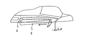
- FIG. 10 is a view of the state in which the vehicle door 2 is opened as viewed from the rear of the vehicle.
- FIG. 11A and FIG. 11B have shown the state from which the vehicle door of the front seat of the vehicle right side opened with respect to the advancing direction from the vehicle upper side.
- the vehicle door 2 is supported by the body 3 so as to be rotatable about a rotation shaft 4 in a hinge portion 2 a disposed on the front side of the vehicle door 2.
- FIG. 11A when the operator of the vehicle door 2 opens the vehicle door 2, the vehicle door 2 moves so that the vehicle door is displaced by a pop-up amount of a slight distance (Lp). A pop-up that opens the vehicle door 2 by a slight angle is possible.
- FIG. 11B the operator of the vehicle door can open the vehicle door as usual.
- a vehicle door opening / closing device described in Patent Literature 1 or an automobile door control device described in Patent Literature 2 is used to control the hinge 2a of the vehicle door 2 by electrical control. It is also possible to adjust the opening by rotating the part with a motor.
- the configuration of the control device becomes complicated for controlling the motor, and the weight increases because the control device is mounted.
- Patent Literature 3 discloses a vehicle door pop-up device.
- the door checker corresponds to the plate 21 of Patent Document 4.
- the check plate 6 of the door checker of Patent Document 3 corresponds to the check link 57 in FIG. 12 of the present application.
- the pop-up device can be realized by arranging a mechanism that pushes the end of the automobile door checker on the side opposite to the side pivoted on the body. .
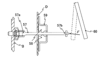
- a typical example of the pop-up device similarly to the door checker described in Patent Document 3, one end 57a of the elongated check link 57 is rotatably supported by the body B of the vehicle.
- the check link 57 is inserted into a door check case 59 supported by the body B, and the upper and lower surfaces are pressed by a pressing member 58 disposed in the door check case 59.
- the door check case 59 is attached to the vehicle door D.
- the door check link 57 and the door check case 59 are arranged so that they can move relative to each other.
- the opening of the vehicle door is adjusted by holding the plate 21 with the stopper 22.
- the pop-up device for example, on the side of the end 57b opposite to the check link 57 and in the direction in which the check link 57 extends, as a force applying member not described in Patent Document 3 and Patent Document 4. It is possible to arrange a pop-up lever 60 that can be moved.
- the pop-up lever 60 applies a force to the end portion 57 b of the check link 57.
- the vehicle door D is closed when the vehicle door D is positioned closer to the body B, and the vehicle door D is open when the vehicle door D is separated from the body B.
- the pop-up of the vehicle door D is realized by rotating the other end portion 57 b of the check link 57 and applying a force (F) by the pop-up lever 60.
- the door check case 60 is moved relative to the check link 57 along the check link 57 by the inertial force P. Moving.
- the vehicle door D fixed to the door check case 60 moves by a slight pop-up distance toward the other end 57b of the check link 57, and the vehicle door D opens slightly.
- the pop-up sequence be configured so that force can be applied to the other end portion of the check link with a pop-up lever by a simple configuration without using electrical control.
- the vehicle door pop-up device is attached to the vehicle body, one end of which is disposed on the other end side of the check link configured to be rotatably supported by the vehicle body, and the rotation A pop-up lever that rotates about a rotation axis of the pop-up lever, and a pop-up arm that applies a force so as to perform the relative movement of the check link in a direction in which the vehicle door opens on one end side of the pop-up lever.
- the crank lever moves along the outer peripheral surface of the cam portion when the cam portion rotates around the cam shaft and rotates in one direction of the outer peripheral surface of the cam portion and the cam portion.
- the pop-up arm solves the problem with a pop-up device that applies force to the check link to urge the relative movement to pop up the vehicle door.
- FIG. 1 is a diagram showing a pop-up device of the present invention in Embodiment 1.
- the pop-up device includes a pop-up lever 1, a cam portion 15, a check link 7, and a door check 9.
- the vehicle door 2 is supported by the body 3 so as to be rotatable around the rotation shaft 4 in a hinge portion 2 a disposed on the front side of the vehicle door 2 as in the conventional case.
- a check link 7 is attached in the vicinity of the hinge portion 2 a of the vehicle door 2 in order to adjust the opening degree of the vehicle door 2.
- the check link 7 has a long and thin shape, and one end 7a of the check link 7 is rotatably supported by the body 3.
- the other end 7b of the check link 7 on the opposite side to the one end 7a side supported by the body 3 is inserted into the vehicle door 2 from the hole in the wall surface of the vehicle door 2 on the side where the hinge portion 2a of the vehicle door 2 is arranged. Has been inserted.
- the pop-up lever 1 is attached to the other end 7b side of the check link 7 where the check link 7 extends.
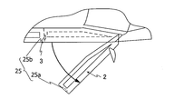
- the vehicle door 2 has a latch mechanism 25 having a latch claw 25a on the end surface of the vehicle door 2 on the side opposite to the hinge 2a and a hook 25b on the corresponding body portion so that the vehicle door does not open when closed. is doing.
- the latch mechanism 25 is engaged with the body 3 in a state where the vehicle door 2 is closed by engaging the latch claw 25a with the hook 25b. In this state, the vehicle door 2 is not opened.
- the engagement between the latch claw 25a and the hook 25b is released, the engagement between the vehicle door 2 and the body 3 is released.
- the latch mechanism 25 is released by the latch release device 2b.
- One end of a first wire member 21 made of an elongated member such as a wire is connected to the lever of the latch release device.
- the other end of the first wire member 21 is connected to one end of the latch release link 22.
- the other end of the latch release link 22 is connected to one end of a second wire member 23 which is similarly formed of an elongated member such as a wire.
- the second line member 23 is connected to a latch claw 25 a of the latch mechanism 25.
- the latch release link 22 is rotatable so as to swing around the rotation shaft 26.
- a pendulum member 24 is attached to the latch release link 22 so as to be rotatable around a swing shaft 24a so as to be swingable in the direction in which the latch release link 22 rotates.
- a protrusion 24 a protrudes from the pendulum member 24.
- the rotation of the latch release link 22 is described as a part of a series of operations of the pop-up, but separately from the pop-up, the vehicle door 2 and the body 3 are rotated by the rotation of the latch release link 22. It is also possible to perform only locking and release thereof with the cam portion.
- a door check 9 having a through hole is fixed to the inner wall 2b of the vehicle door 2.
- the check link 7 is inserted into the through hole 9a of the door check 9 so that the door check 9 is positioned between the one end 7a and the other end 7b of the check link 7.
- a pressing member 8 that presses the surface of the check link 7 is disposed inside the door check 9.
- the door check 9 slides while the pressing member 8 presses the sliding surface of the check link 7. That is, the door check 9 can move relative to the check link 7 between one end 7 a and the other end 7 b of the check link 7.
- the pop-up lever 1 is attached so as to be rotatable around the rotation shaft 1a.
- One end of the pop-up lever 1 is disposed so as to be positioned at a location extending from the other end 7b of the check link 7 in a separated state so that a pressing force can be applied to the other end 7b of the check link 7.
- 7 functions as a pressing portion 4c that presses the other end 7b of 7.
- a crank lever 10 is attached to the other end side of the pop-up lever 1.
- a driven portion 10 a is disposed at the end opposite to the side on which the pop-up lever 1 is attached. When the driven portion 10a is pushed, the pop-up lever 1 rotates around the rotation shaft 1a.
- the cam portion 15 is rotatably attached around the cam shaft 15a, and has an outer peripheral surface on the outer periphery of the cam portion 15.
- the driven portion 10a of the crank lever 10 can move along the outer peripheral surface.
- the cam portion 15 can typically include a first cam member 16 and a second cam member 17. In the present embodiment, an example in which the first cam member 16 and the second cam member 17 are provided will be described.
- the first cam member 16 has a first outer peripheral portion 16a having a circumferential surface whose radius is the first distance R1 from the cam shaft 15a, and a circumferential surface whose radius is the third distance R3 from the cam shaft 15a.
- the first distance R1 to the third distance R3 are constants, and the second distance R2 is a variable that increases at a constant rate from the first distance R1 to the third distance R3.
- the driven portion 10a of the crank lever 10 is positioned so as to be in contact with the track of the first outer peripheral portion 16a and the second outer peripheral portion 16b of the first cam member 16. Therefore, the driven portion 10a of the crank lever 10 is movable along at least the first outer peripheral portion 16a and the second outer peripheral portion 16b of the first cam member 16.
- the driven portion 10a of the crank lever 10 moves from its original position along with it.
- the angle of the crank lever 10 changes and the pop-up lever 1 rotates around the rotation axis 1a.
- the portion of the third distance R3 between the first cam member 16 and the second cam member 17 is not necessarily in contact with the driven portion 10a of the crank lever 10, but may be set to contact. Even if they are brought into contact with each other, according to the rotation of the first cam member 16, the driven portion 10a of the crank lever 10 is fixed at a constant third distance from the cam shaft 15a for a fixed time corresponding to the portion of the third distance R3. R3 is maintained, and the state where the angle of the crank lever 10 is not changed is maintained.
- the second cam member 17 is a cam having a smaller radius than the first cam member 16.
- the second cam member 17 typically has at least a part of the outer peripheral surface of the first cam member 16 that coincides with the outer peripheral surface having a circumferential surface having a radius of the third distance R3 from the cam shaft 15a. have.
- the second cam member 17 is a cam having an outer peripheral shape having a radius portion smaller than the third distance R3 in the other portion.
- the first cam member 16 and the second cam member 17 are coaxially overlapped with the cam shaft 15a so as to have an outer peripheral shape having a radius portion smaller than the third distance R3. It is attached.
- the first cam member 16 and the second cam member 17 rotate as a unit.
- the protrusion 24a of the pendulum member 24 of the latch release link 22 is located on the outer peripheral track portion having a radius portion smaller than the third distance R3 between the first cam member 16 and the second cam member 17.
- the position of the protrusion 24a of the pendulum member 24 of the latch release link 22 is set so as to be located at a position that is smaller than the third distance R3 from the cam shaft 15a. Since the second cam member 17 has an outer peripheral shape having a radius portion smaller than the third distance R3 at portions other than the portion having the third distance R3, the second cam member 17 has the third distance R3.
- the protrusion 24a When the outer peripheral portion having a point comes to the position of the protrusion 24a, the protrusion 24a is pushed by the outer peripheral portion having the third distance R3, and the pendulum member 24 rotates. As a result, the end of the pendulum member 24 a pushes up the latch release link 22 and rotates the latch release link 22 around the rotation shaft 26. Accordingly, even if the first wire member 21 is not pulled, the second wire member 23 pulls the latch claw 25a of the latch mechanism 25, and the latch claw 25a is disengaged from the hook 25b of the body portion, so that the engagement is released. it can.
- the contact points of the limit switch 31 and the limit switch 32 are arranged on the outer peripheral track portion having a radius smaller than the third distance R3 between the first cam member 16 and the second cam member 17.
- the limit switch 32 is arranged so that the contact point is located at a position where the tip of the third distance R3 comes after the cam portion 15 finishes the rotation of the pop-up lever 1 and the latch release link 22.
- the limit switch 32 is set so that the rotation direction of the cam portion 15 is reversed when turned on.
- the cam portion 15 is returned to the initial state.
- the cam portion 15 is set to stop when the rear end of the third distance R3 part presses the limit switch 31 again. can do.
- FIGS. 1 to 4 are views before pop-up, showing a state in which the vehicle door 2 is closed.
- FIG. 5 to FIG. 7 show the state during the pop-up operation.
- 8 and 9 show a state after the pop-up operation is completed until the cam portion 15 returns to the initial position.
- the pop-up lever 1 is located away from the check link 7.
- the driven portion 10a of the crank lever 10 is located at a location corresponding to the third distance R3 of the cam portion 15.
- the cam portion 15 When the operator of the vehicle door 2 turns on the pop-up device, the cam portion 15 first moves around the cam shaft 15a after the second outer peripheral portion 16b of the first cam member 16 comes into contact with the driven portion 10a of the crank lever 10 first. Rotation is started in a direction in contact with one outer peripheral portion 16a. Once the rotation starts, the cam portion 15 rotates in the same direction without stopping until the limit switch 31 or the limit switch 32 operates. As the cam portion 15 rotates around the cam shaft 15a, before the second outer peripheral portion 16b of the first cam member 16 comes into contact with the driven portion 10a of the crank lever 10, as shown in FIG. The tip of the portion corresponding to the third distance R3 contacts the pendulum member 24. Then, as shown in FIG.
- the second outer peripheral portion 16b of the first cam member 16 contacts the driven portion 10a of the crank lever 10 as shown in FIG. Touch. This is the starting point of the pop-up operation (S03 in FIG. 2). Since the second outer peripheral portion 16b is a portion where the distance from the cam shaft 15 to the outer peripheral surface increases at a constant rate, the driven portion 10a of the crank lever 10 moves away from the cam shaft 15 as the cam portion 15 rotates. And the attitude angle of the crank lever 10 changes. Due to the change in the posture angle, the pop-up lever 1 rotates around the rotation axis 1a. The driven portion 10a of the crank lever 10 is located on the second outer peripheral portion 16b at any position between FIG. 5 and FIG.
- the driven portion 10a of the crank lever 10 moves from the first outer peripheral portion 16a of the first cam member 16 to the second outer peripheral portion 16b, and the pop-up arm 1 moves in the opposite direction to that during pop-up.
- the driven portion 10a of the crank lever 10 is separated from the outer peripheral portion of the cam portion 15, and the pop-up arm 1 is completely stored (S09 in FIG. 2).
- the limit switch 31 is turned on at a location corresponding to the third distance R3 of the cam portion 15, the rotation of the motor that has been rotating the cam portion 15 at this time stops, and a series of pop-up operations ends.
- the second cam member 17 is used to rotate the latch release link 22 and the limit switch, but the first cam member 16 may perform the rotation. It can be freely set by the operation timing of the latch release link 22, the operation timing of the pop-up lever 1, and the timing of the limit switch operation.
- the start time of S03 in FIG. 2 can be simultaneous with respect to S02 in FIG. 2, or the start of S03 in FIG. 2 can be set before S02 in FIG.
- the example which attached the 2nd cam member 16 and the 2nd cam member 17 coaxially with the cam shaft was demonstrated, it can also be rotated on a different axis
Landscapes
- Engineering & Computer Science (AREA)
- Mechanical Engineering (AREA)
- Lock And Its Accessories (AREA)
Abstract
ポップアップシーケンスを電気的な制御によらずに、簡易な構成により、ポップアップレバーでチェックリンクの他端部に力を付与できるように構成する。車両ドア(2)に固定されるドアチェック(9)と、一端が車両ボディ(3)に回動可能に支持されるチェックリンク(7)であって、前記ドアチェック(9)から押圧力を付与されながら前記一端と前記チェックリンク(7)の他端との間を前記ドアチェック(9)に対して相対的な移動を行う前記チェックリンク(7)と、前記チェックリンク(7)の前記他端の側に配置され、回動軸回りに回動するポップアップレバー(1)であって、そのポップアップレバー(1)の一端の側で前記車両ドア(2)が開く方向に前記チェックリンク(7)の前記相対的な移動を行うように力を付与するポップアップアーム(1)と、カム軸回りに回動し、外周面を有するカム部(15)と、前記カム部(15)の前記外周面に沿って移動するクランクレバー(10)とを備えるポップアップ装置により解決する。
Description
この発明は、たとえば乗用自動車などの車両における車両ドアを開く際に、僅かな角度だけ車両ドアを開くポップアップ装置に関する。
車両に乗車する際において、車両ドアを開けようとする者の手がふさがっている場合がある。さらに、この状況において、車両に隣接する物体との間に十分な空間が無い場合には、その物体に車両ドアが接触しないようにする必要もある。このような場合には、意図しない開度まで車両ドアが開くことがないように、車両の内側に向かって車両ドアを手で支えながら、車両に隣接する物体と接触しないように、静かに車両ドアを開くことになる。そのため、車両ドアを開ける際に、車両ドアの縁を保持できるように、車両ドアを開ける際の初期動作として、僅かな角度だけ車両ドアを開くこと(本明細書中、「ポップアップ」とよぶ)ができる装置を提供することが考えられる。
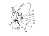
図10は、車両ドア2が開いた状態を車両の後方から見た図である。また、図11Aおよび図11Bは、進行方向に対して車両右側の前座席の車両ドアが開いた状態を車両の上側から示している。車両ドア2は、一般に、車両ドア2の前方側に配置されるヒンジ部2aにおいて、回動軸4まわりに回動可能にボディ3に支持されている。図11Aに示すように、車両ドア2の操作者が車両ドア2を開ける際には、車両ドア2は、僅かな距離(Lp)のポップアップ量だけ、車両ドアがずれるように移動することで、僅かな角度だけ車両ドア2が開くポップアップが可能となる。その後、図11Bに示すように、車両ドアの操作者は、通常どおり車両ドアを開くことができる。
ポップアップ装置を実現するには、たとえば、特許文献1に記載されている車両ドア開閉装置または特許文献2に記載されている自動車ドア制御装置のように、電気的制御により車両ドア2のヒンジ2aの部分をモータにより回転させることで開度を調整することによることもできる。しかし、このように、ソフトウェアによる制御では、そのモータの制御のため制御機器の構成が複雑になるとともに、制御機器を搭載するために重量が増加する。
そこで、たとえば、特許文献3に記載されている自動車用ドアチェッカまたは特許文献4に記載されている車両用ドアの開度調整装置を一部に利用することが考えられる。特許文献3および特許文献4のいずれも、車両ドアのポップアップ装置を開示しているものではない。特許文献3の自動車用ドアチェッカでは、一端がボディに枢支されるドアチェッカに対して、相対的に摺動するように配置したケースが車両ドアに取り付けられる。そのドアチェッカは、特許文献4のプレート21に対応する。特許文献3のドアチェッカのチェックプレート6は、本願の図12におけるチェックリンク57に対応する。ここで、ポップアップ装置は、たとえば、本願の図12に示すように、ボディに枢支されている側と反対側の自動車用ドアチェッカの端部を押すような機構を配置することにより実現ができる。ポップアップ装置の代表例では、特許文献3に記載されているドアチェッカと同様に、細長い形状のチェックリンク57の一端57aが車両のボディBに回転可能に支持されている。チェックリンク57は、ボディBに支持されているドアチェックケース59内に挿入されていて、ドアチェックケース59内に配置される押圧部材58により上下面が押圧されている。ドアチェックケース59は、車両ドアDに取り付けられている。ドアチェックリンク57とドアチェックケース59とは、それぞれに対して相対的に移動が可能なように配置される。特許文献4では、さらに、ストッパ22でプレート21を挟持して車両ドアの開度を調整している。
ポップアップ装置では、たとえば、チェックリンク57の反対側の端部57bの側であって、チェックリンク57が延在する方向に、特許文献3および特許文献4には記載されていない力付与部材としての搖動可能なポップアップレバー60を配置することが考えられる。ポップアップレバー60はチェックリンク57の端部57bに力を付与する。図12において、車両ドアDがボディBに近い側に位置する際に車両ドアDは閉じており、車両ドアDがボディBから離れれば、車両ドアDは開いていることになる。ここで、車両ドアDのポップアップは、チェックリンク57の他端部57bを回動して、ポップアップレバー60により力(F)を付与することで実現する。たとえば、回動可能なポップアップレバー60でチェックリンク57の他端部57bに力Fを付与すると、ドアチェックケース60は慣性力Pによりチェックリンク57に沿って、チェックリンク57に対して相対的に移動する。ドアチェックケース60に固定されている車両ドアDは、チェックリンク57の他端部57b側に僅かなポップアップ距離だけ移動し、車両ドアDは僅かに開く。
しかし、ポップアップレバーでチェックリンクの他端部に力Fを付与する場合であっても、安定したポップアップを実現するためには、所定のシーケンスが所定の時間で実現される必要が生じる。このポップアップシーケンスを電気的な制御によらずに、簡易な構成により、ポップアップレバーでチェックリンクの他端部に力を付与できるように構成することが望まれる。
車両ドアに固定されるドアチェックと、一端が車両ボディに回動可能に支持されるチェックリンクであって、前記ドアチェックから押圧力を付与されながら前記一端と前記チェックリンクの他端との間を前記ドアチェックに対して相対的な移動を行う前記チェックリンクと、前記チェックリンクの前記他端の側に配置され、回動軸回りに回動するポップアップレバーであって、そのポップアップレバーの一端の側で前記車両ドアが開く方向に前記チェックリンクの前記相対的な移動を行うように力を付与するポップアップアームと、カム軸回りに回動し、外周面を有するカム部と、前記カム部の前記外周面に沿って移動するクランクレバーとを備えるポップアップ装置により解決する。
また、車両ボディに対して取り付けられる車両ドアのポップアップ装置であって、一端が車両ボディに回動が可能に支持されるように構成されるチェックリンクの他端の側に配置され、前記回動の回動軸回りに回動するポップアップレバーであって、そのポップアップレバーの一端の側で前記車両ドアが開く方向に前記チェックリンクの前記相対的な移動を行うように力を付与するポップアップアームと、カム軸回りに回動し、外周面を有するカム部と、前記カム部の前記外周面の一の方向に回転する際に、前記カム部の前記外周面に沿って前記クランクレバーが移動し、前記ポップアップアームの前記一端が前記チェックリンクに力を付与して前記相対的な移動を喚起して車両ドアのポップアップを行うポップアップ装置により解決する。
制御系を電気的に構成することなく、カムによりポップアップレバーを所定のシーケンスで動作させてチェックリンクの他端部に力を付与することができる。
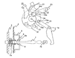
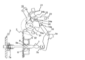
以下、図1を参照して、本発明の車両ドア2のポップアップ装置について説明する。図1は、実施の形態1における本発明のポップアップ装置を示した図である。ポップアップ装置は、ポップアップレバー1と、カム部15と、チェックリンク7と、ドアチェック9とを備える。
図10に示すように、車両ドア2は、従来と同様に、車両ドア2の前方側に配置されるヒンジ部2aにおいて、回動軸4まわりに回動可能にボディ3に支持されている。車両ドア2のヒンジ部2a付近には、車両ドア2の開度を調整するために、チェックリンク7がとりつけられている。チェックリンク7は、長細い形状であって、チェックリンク7の一端7aがボディ3に回転可能に支持されている。ボディ3に支持されているその一端7a側と反対側にあたるチェックリンク7の他端7bは、車両ドア2のヒンジ部2aが配置される側の車両ドア2の壁面の孔から車両ドア2内に挿入されている。チェックリンク7が延在するチェックリンク7の他端7bの側には、ポップアップレバー1が取り付けられている。車両ドア2は、閉じた際に車両ドアが開かないように、ヒンジ2aと反対側の車両ドア2の端面にラッチ爪25aと、それに対応するボディ部にフック25bとを備えるラッチ機構25を有している。ラッチ機構25は、ラッチ爪25aがフック25bに係合することにより、車両ドア2が閉じた状態でボディ3に係合される。この状態では、車両ドア2は開かない。一方、ラッチ爪25aとフック25bとの係合が解除されることにより、車両ドア2とボディ3との係合が解除される。この状態で、車両ドア2に対して外向きの力を与えると、車両ドア2がボディ3から離間して車両ドア2が開く。ラッチ機構25は、ラッチ解除装置2bにより解除される。ラッチ解除装置のレバーには、たとえばワイヤなどの細長い部材からなる第一の線部材21の一端が接続されている。第一の線部材21の他端はラッチ解除リンク22の一端に接続されている。ラッチ解除リンク22の他端には、同様にワイヤなどの細長い部材からなる第二の線部材23の一端が接続されている。第二の線部材23は、ラッチ機構25のラッチ爪25aに接続されている。ラッチ解除リンク22は、回動軸26を中心に搖動するように回転可能である。ラッチ解除装置2bのレバーを引くと第一の線部材21が引っ張られて、ラッチ解除リンク22が回動軸26周りに回動する(たとえば、図1のラッチ解除リンク22の姿勢から図4のラッチ解除リンク22の姿勢に変化する)。これにより、第二の線部材23がラッチ機構25のラッチ爪25aを引っ張って、ラッチ爪25aがボディ部のフック25bから外れて、係合が解除される。一方、係合する際には、ラッチ爪25aがフック25b内に挿入されると、ラッチ爪25aとフック25bとが自動的に係合する。ラッチ解除装置2bを戻せば、第一の線部材21と第二の線部材23とが元の状態に押し戻され、ラッチ解除リンク22の姿勢も元に戻る。この元に戻るプロセスはラッチ爪25aとフック25bとの係合には寄与しない。ラッチ解除リンク22には、振り子部材24がラッチ解除リンク22の回動する方向に搖動可能に搖動軸24a周りに回動可能に取り付けられている。振り子部材24には、突起24aが突出している。本実施例においては、ラッチ解除リンク22の回動はポップアップの一連の動作の一部として説明をしているが、ポップアップとは別に、ラッチ解除リンク22の回動により、車両ドア2とボディ3との係止およびその解除のみをカム部によって単独に行うことも可能である。
車両ドア2の内壁2bには、貫通孔を有するドアチェック9が固定されている。チェックリンク7は、チェックリンク7の一端7aと他端7bとの間に、ドアチェック9が位置するようにドアチェック9の貫通孔9aに挿入されている。ドアチェック9の内部には、チェックリンク7の面を押圧する押圧部材8が配置されている。ドアチェック9は、押圧部材8がチェックリンク7の摺動面を押圧しながら摺動する。すなわち、ドアチェック9は、チェックリンク7の一端7aと他端7bとの間を、チェックリンク7に対して相対的に移動可能である。ポップアップレバー1は、回動軸1a周りに回動可能に取り付けられている。ポップアップレバー1の一端は、チェックリンク7の他端7bに押圧力を加えられるように、離間した状態で、チェックリンク7の他端7bから延在する箇所に位置するように配置され、チェックリンク7の他端7bを押す押圧部4cとして機能する。ポップアップレバー1の他端側には、クランクレバー10が取り付けられている。クランクレバー10において、ポップアップレバー1が取り付けられている側と反対側の端部には、従動部10aが配置される。従動部10aが押されると、ポップアップレバー1が回動軸1a周りに回転するようになっている。
カム部15は、カム軸15a周りに回動可能に取り付けられ、カム部15の外周には外周面を有する。クランクレバー10の従動部10aは、この外周面に沿って移動可能なようになっている。カム部15は、代表的には、第一カム部材16と、第二カム部材17とを備えるようにできる。本実施の形態では、第一カム部材16と、第二カム部材17とを備える例で説明する。第一カム部材16は、カム軸15aから第一の距離R1を半径とする円周面を持つ第一外周部16aと、カム軸15aから第三の距離R3を半径とする円周面を持つ外周面とを有していて、その間に、第一の距離R1から第三の距離R3に滑らかにつながるような第二の距離R2を半径とする曲線面を外周面とする第二外周部16bとを有している。第一の距離R1から第三の距離R3は定数であり、第二の距離R2は第一の距離R1から第三の距離R3に至るまで、一定の割合で増加する変数である。第一カム部材16の第一外周部16aと第二外周部16bの軌道には、クランクレバー10の従動部10aが接触可能に位置する。したがって、クランクレバー10の従動部10aは、少なくとも、第一カム部材16の第一外周部16aと第二外周部16bに沿って移動可能となっている。すなわち、第二外周部16bは半径が一定の割合で増加するので、第一カム部材16がカム軸15a周りに回動すると、クランクレバー10の従動部10aは、それに沿って元の位置から移動し、これによりクランクレバー10の角度が変化してポップアップレバー1が回動軸1a周りに回動する。第一カム部材16と第二カム部材17との第三の距離R3の部分には、必ずしもクランクレバー10の従動部10aを接触させる必要はないが、接触するように設定しても良い。接触させたとしても、第一カム部材16の回転に応じて、クランクレバー10の従動部10aは、第三の距離R3の部分に対応する一定時間だけ、カム軸15aから一定の第三の距離R3を保って、クランクレバー10の角度を変えない状態を保つことになる。
第二カム部材17は、第一カム部材16よりも半径の小さいカムである。第二カム部材17は、代表的には、少なくともその一部において、第一カム部材16において、カム軸15aから第三の距離R3を半径とする円周面を持つ外周面と一致する外周面を持つ。第二カム部材17は、それ以外の部分に、第三の距離R3よりも小さい半径部を持つ外周形状を有するカムである。第一カム部材16と第二カム部材17とは、それぞれの第三の距離R3よりも小さい半径部を持つ外周形状が一致するように、カム軸15aに同軸で、一体となるように重ねて取り付けられる。第一カム部材16と第二カム部材17とは、一体として回転する。第一カム部材16と第二カム部材17との第三の距離R3よりも小さい半径部を持つ外周形状の軌道部分には、ラッチ解除リンク22の振り子部材24の突起24aが位置している。ラッチ解除リンク22の振り子部材24の突起24aの位置は、カム軸15aから第三の距離R3より小さい距離となる箇所に位置するように設定する。第二カム部材17において、第三の距離R3を有する部分以外の箇所では、第三の距離R3よりも小さい半径部を持つ外周形状を有するので、第二カム部材17において、第三の距離R3を有する外周部分が突起24aの箇所に来ると、第三の距離R3を有する外周部分に突起24aが押されて振り子部材24が回転する。これにより、振り子部材24aの端部がラッチ解除リンク22を押し上げて、ラッチ解除リンク22を回動軸26周りに回動させる。これにより、第一の線部材21を引っ張らなくても、第二の線部材23がラッチ機構25のラッチ爪25aを引っ張って、ラッチ爪25aがボディ部のフック25bから外れて、係合が解除できる。
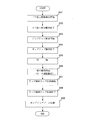
第一カム部材16と第二カム部材17との第三の距離R3よりも小さい半径部を持つ外周形状の軌道部分には、リミットスイッチ31とリミットスイッチ32のそれぞれの接点が配置される。まず、第二カム部材17の第三の距離R3よりも小さい半径部を持つ外周部がリミットスイッチ31に接触すると、そこから図2に示す一連のポップアップシーケンスが開始されるトリガ信号となる。一方、リミットスイッチ32は、カム部15がポップアップレバー1とラッチ解除リンク22との回動を終えた後に、第三の距離R3の部分の先端が来る位置に接点が位置するように配置される。このリミットスイッチ32は、オンにされるとカム部15の回転方向が反転するように設定されている。したがって、ポップアップレバー1とラッチ解除リンク22との回動を終えた後に、カム部15を初期状態に戻す役割を有している。そして、リミットスイッチ32がオンにされてカム部15が初期位置にもどったときに、第三の距離R3の部分の後端がリミットスイッチ31を再度押すと、カム部15が停止するように設定することができる。
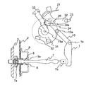
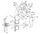
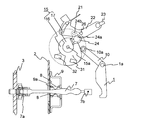
続いて、図1から図9を参照して、本発明のポップアップ装置の動作について説明する。図1から図4は、ポップアップ前の図であって、車両ドア2が閉じた状態を示した図である。図5から図7はポップアップの動作中の状態を示している。図8および図9は、ポプアップ動作終了後に、カム部15が初期位置に戻るまでの状態を示している。図1に示すように、ポップアップレバー1は、チェックリンク7から離間して位置している。クランクレバー10の従動部10aは、カム部15の第三の距離R3に対応する箇所に位置している。車両ドア2の操作者がポップアップ装置をオンにすると、カム部15がカム軸15a周りに第一カム部材16の第二外周部16bが先にクランクレバー10の従動部10aに当接してから第一外周部16aに当接する方向に回転を開始する。一旦、回転を開始すると、リミットスイッチ31またはリミットスイッチ32が動作するまで、カム部15は止まることなく、同じ方向に回転する。カム部15がカム軸15a周りに回転するにしたがって、図3に示すように、第一カム部材16の第二外周部16bがクランクレバー10の従動部10aに当接する前に、カム部15の第三の距離R3に対応する箇所の先端が振り子部材24に当接する。そして、図4に示すように、カム部15の第三の距離R3に対応する箇所が突起24aに当接し(図2のS01)、振り子部材24aの端部がラッチ解除リンク22を押し上げて、ラッチ解除リンク22を回動軸26周りに回動させる。これにより、ラッチ解除リンク22が第二の線部材23を引っ張る。そして、第二の線部材23がラッチ機構25のラッチ爪25aを引っ張って、ラッチ爪25aがボディ部のフック25bから外れて係合が解除される(図2のS02)。
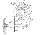
車両ドア2の係止が解除されると、ほぼ同時または所定の時間が経過後に、図5に示すように、第一カム部材16の第二外周部16bがクランクレバー10の従動部10aに当接する。ここがポップアップ動作の開始点となる(図2のS03)。第二外周部16bは、カム軸15から外周面までの距離が一定の割合で増加する部分であるので、カム部15の回転にしたがって、クランクレバー10の従動部10aはカム軸15から離れるように移動し、クランクレバー10の姿勢角が変化する。この姿勢角の変化により、ポップアップレバー1が回動軸1a周りに回動する。クランクレバー10の従動部10aが第二外周部16bにある図5と図6の間の位置のいずれかの位置で、ポップアップレバー1の一端1b側が、チェックリンク7の他端7bに接触して、チェックリンク7を長手方向に押圧する。その衝撃の慣性力により、チェックリンク7とドアチェック9とは、相対的な移動を行い、ドアチェック9が取り付けられている車両ドア2が僅かに開くポップアップ動作を行う。やがて、図6に示すように、第一カム部材16の第一外周部16aの先端がクランクレバー10の従動部10aに当接してポップアップ動作が終了する(図2のS04)。第一カム部材16の第一外周部16aの先端がクランクレバー10の従動部10aに当接する間は、クランクレバー10の従動部10aはカム軸15から第一距の離R1を保っているので、その間はポップアップレバー1は退避できず、そのままの状態で所定の時間(たとえば、30秒程度)だけ待機をおこなう(図2のS05)。そして、図7に示すように、カム部15の第三の距離R3に対応する箇所の先端がリミットスイッチ32をオンにするとカム部15は、反対方向に向かって逆の回転を始める(図2のS06)。そして、図8に示すようにカム部15の第三の距離R3に対応する箇所が突起24aに当接すると、振り子部材24はラッチ解除リンク22が第二の線部材23を押し戻す方向に回動してラッチ解除リンク22の収納動作が開始される(図2のS07)。その後、図9に示すように、振り子部材24がラッチ解除リンク22に当接して、ラッチ解除リンク22が第二の線部材23を完全に押し戻してラッチ解除リンク22の収納が終了する(図2のS08)。その後は、クランクレバー10の従動部10aが、第一カム部材16の第一外周部16aから第二外周部16bに移動し、ポップアップアーム1がポップアップ時と逆に移動する。所定の位置で、クランクレバー10の従動部10aがカム部15の外周部から離間して、ポップアップアーム1が完全に収納される(図2のS09)。カム部15の第三の距離R3に対応する箇所がリミットスイッチ31をオンにすると、この時点でカム部15の回動を行っていたモータの回転が止まり、一連のポップアップ動作が終了する。
なお、本実施の形態においては、第二カム部材17を用いて、ラッチ解除リンク22の回動と、リミットスイッチの動作を行ったが、第一カム部材16により行っても良い。ラッチ解除リンク22の動作タイミングと、ポップアップレバー1の動作タイミング、リミットスイッチ動作のタイミングで、自由に設定できる。たとえば、図2のS03の開始の時点は図2のS02との関係において同時にすることもでき、または図2のS03の開始を図2のS02の前に設定することもできる。また、第二カム部材16と第二カム部材17とをカム軸で同軸に取り付けた例で説明したが、異なる軸で回転させることもできる。カム部15全体として、これらの動作を行うように設定する限り、カム部15を構成するカム部材の個数や、配置位置は自由に設定できる。
この出願は2014年11月27日に出願された日本国特許出願第2014-240535号からの優先権を主張するものであり、その内容を引用してこの出願の一部とするものである。
1 ポップアップレバー
1a 回動軸
2 車両ドア
3 ボディ
7 チェックリンク
8 押圧手段
9 ドアチェック
10 クランクレバー
15 カム部
16 第一カム部材
17 第二カム部材
22 ラッチ解除リンク
1a 回動軸
2 車両ドア
3 ボディ
7 チェックリンク
8 押圧手段
9 ドアチェック
10 クランクレバー
15 カム部
16 第一カム部材
17 第二カム部材
22 ラッチ解除リンク
Claims (6)
- 車両ドアに対して固定されるように構成されるドアチェックと、
一端が車両ボディに対して回動可能に支持されるように構成されるチェックリンクであって、前記ドアチェックから押圧力を付与されながら前記一端と前記チェックリンクの他端との間を前記ドアチェックに対して相対的な移動を行う前記チェックリンクと、
前記チェックリンクの前記他端の側に配置され、回動軸回りに回動するポップアップレバーであって、そのポップアップレバーの一端の側で前記車両ドアが開く方向に前記チェックリンクの前記相対的な移動を行うように力を付与するポップアップアームと、
カム軸回りに回動し、外周面を有するカム部と、
前記カム部の前記外周面に沿って移動するクランクレバーとを備え、
前記カム部が前記カム軸の一の方向に回転する際に、前記カム部の前記外周面に沿って前記クランクレバーが移動し、前記ポップアップアームの前記一端が前記チェックリンクに力を付与して前記相対的な移動を喚起して車両ドアのポップアップを行うポップアップ装置。 - 請求項1に記載の車両ドア用のポップアップ装置であって、
前記相対的な移動の完了の時またはその後に、前記カム部が前記一の方向と反対の方向に回転するように、前記カム部の駆動装置の回転方向の切り替えを行う切替スイッチが前記カム部の位置に応じて反応する時と、の間に所定の時間の間隔を有するポップアップ装置。 - 請求項1または2に記載の車両ドア用のポップアップ装置であって、
前記相対的な移動の完了した後において、前記カム部が前記一の方向と反対の方向に回転するように、前記カム部の駆動装置の回転方向の切り替えを行う切替スイッチが前記カム部の位置に応じて反応して前記カム部が前記反対の方向に回転し、前記ポップアップアームが元の位置に戻るポップアップ装置。 - 請求項1から3のいずれか一項に記載の車両ドア用のポップアップ装置であって、
前記車両ドアは、閉じられている際に前記車両ドアを前記車両ボディへの係止とその係止の解除を行うラッチ機構と、前記係止と前記解除とを行うためのラッチ解除装置とを備え、
一端が第一の線部材により前記ラッチ解除装置に接続され、他端が第二の線部材により前記ラッチ機構に接続され、回動が可能なラッチ解除リンクを備え、
前記ラッチ解除装置により前記第一の線部材が引かれると前記ラッチ解除リンクは前記回動を行って前記第二の線部材を引いて前記ラッチ機構が前記係止の前記解除を行うようになっていて、
前記カム部が前記カム軸の前記一の方向に前記回転を行って、前記ポップアップアームの前記一端が前記チェックリンクの前記相対的な移動を喚起する際に、前記カム部は前記ラッチ解除リンクが前記第二の線部材を引くような回動を喚起して前記ラッチ機構が前記係止の前記解除を行うポップアップ装置。 - 請求項4に記載の車両ドア用のポップアップ装置であって、
前記カム部が前記反対の方向に回転すると、前記ラッチ解除リンクが前記第二の線部材を押し戻すような回動を喚起して前記ラッチ機構が前記係止を行うポップアップ装置。 - 車両ボディに対して取り付けられる車両ドアのポップアップ装置であって、
一端が車両ボディに回動が可能に支持されるように構成されるチェックリンクの他端の側に配置され、前記回動の回動軸回りに回動するポップアップレバーであって、そのポップアップレバーの一端の側で前記車両ドアが開く方向に前記チェックリンクの前記相対的な移動を行うように力を付与するポップアップアームと、
カム軸回りに回動し、外周面を有するカム部と、
前記カム部の前記外周面の一の方向に回転する際に、前記カム部の前記外周面に沿って前記クランクレバーが移動し、前記ポップアップアームの前記一端が前記チェックリンクに力を付与して前記相対的な移動を喚起して車両ドアのポップアップを行うポップアップ装置。
Priority Applications (2)
| Application Number | Priority Date | Filing Date | Title |
|---|---|---|---|
| US15/526,523 US20170306678A1 (en) | 2014-11-27 | 2015-09-28 | Popup device |
| CN201580064743.8A CN107000554A (zh) | 2014-11-27 | 2015-09-28 | 弹出装置 |
Applications Claiming Priority (2)
| Application Number | Priority Date | Filing Date | Title |
|---|---|---|---|
| JP2014240535A JP2016101815A (ja) | 2014-11-27 | 2014-11-27 | ポップアップ装置 |
| JP2014-240535 | 2014-11-27 |
Publications (1)
| Publication Number | Publication Date |
|---|---|
| WO2016084293A1 true WO2016084293A1 (ja) | 2016-06-02 |
Family
ID=56073893
Family Applications (1)
| Application Number | Title | Priority Date | Filing Date |
|---|---|---|---|
| PCT/JP2015/004900 Ceased WO2016084293A1 (ja) | 2014-11-27 | 2015-09-28 | ポップアップ装置 |
Country Status (4)
| Country | Link |
|---|---|
| US (1) | US20170306678A1 (ja) |
| JP (1) | JP2016101815A (ja) |
| CN (1) | CN107000554A (ja) |
| WO (1) | WO2016084293A1 (ja) |
Families Citing this family (3)
| Publication number | Priority date | Publication date | Assignee | Title |
|---|---|---|---|---|
| CN109515131B (zh) * | 2018-12-17 | 2024-05-17 | 吉林大学 | 一种汽车车门智能防冻及解冻系统 |
| JP2021059965A (ja) * | 2019-10-09 | 2021-04-15 | アイシン精機株式会社 | 車両用ドアチェック装置 |
| CN114475177B (zh) * | 2022-01-14 | 2023-07-21 | 岚图汽车科技有限公司 | 一种可安装在车门上的防夹手装置 |
Citations (3)
| Publication number | Priority date | Publication date | Assignee | Title |
|---|---|---|---|---|
| JPH0350186U (ja) * | 1989-09-22 | 1991-05-16 | ||
| JP2005256313A (ja) * | 2004-03-09 | 2005-09-22 | Oi Seisakusho Co Ltd | 車両用ドア開扉装置 |
| JP2007100342A (ja) * | 2005-10-03 | 2007-04-19 | Honda Motor Co Ltd | ドアの開閉部構造 |
Family Cites Families (1)
| Publication number | Priority date | Publication date | Assignee | Title |
|---|---|---|---|---|
| JP6007745B2 (ja) * | 2012-11-20 | 2016-10-12 | アイシン精機株式会社 | ドア駆動装置 |
-
2014
- 2014-11-27 JP JP2014240535A patent/JP2016101815A/ja active Pending
-
2015
- 2015-09-28 CN CN201580064743.8A patent/CN107000554A/zh active Pending
- 2015-09-28 WO PCT/JP2015/004900 patent/WO2016084293A1/ja not_active Ceased
- 2015-09-28 US US15/526,523 patent/US20170306678A1/en not_active Abandoned
Patent Citations (3)
| Publication number | Priority date | Publication date | Assignee | Title |
|---|---|---|---|---|
| JPH0350186U (ja) * | 1989-09-22 | 1991-05-16 | ||
| JP2005256313A (ja) * | 2004-03-09 | 2005-09-22 | Oi Seisakusho Co Ltd | 車両用ドア開扉装置 |
| JP2007100342A (ja) * | 2005-10-03 | 2007-04-19 | Honda Motor Co Ltd | ドアの開閉部構造 |
Also Published As
| Publication number | Publication date |
|---|---|
| CN107000554A (zh) | 2017-08-01 |
| US20170306678A1 (en) | 2017-10-26 |
| JP2016101815A (ja) | 2016-06-02 |
Similar Documents
| Publication | Publication Date | Title |
|---|---|---|
| JP6427803B2 (ja) | 自動車用ドアラッチ装置 | |
| JP2018109345A5 (ja) | ||
| WO2019172057A1 (ja) | 車両のドアハンドル装置 | |
| WO2021049213A1 (ja) | 車両のハンドル装置 | |
| CN105188478A (zh) | 用于可动的家具部件的驱动装置 | |
| JP2015532952A (ja) | 自動車ドアロック | |
| JP2017193303A (ja) | 車両用コンソール装置 | |
| WO2015064001A1 (ja) | 車両用ドアのポップアップ機構 | |
| JP2016101815A (ja) | ポップアップ装置 | |
| JP7026648B2 (ja) | 車両のドアハンドル装置 | |
| JP2019090196A (ja) | 車両用ドア開閉操作装置 | |
| JP2019534962A (ja) | 可変のトリガ切替え点を有するロック解除ユニット | |
| WO2016084292A1 (ja) | ポップアップ装置 | |
| JP6406541B2 (ja) | 車両ドア開度調整装置 | |
| JP6536890B2 (ja) | 車両ドア開閉システム | |
| JP2020084457A (ja) | 車両用アウトサイドドアハンドル | |
| JP6104752B2 (ja) | ポップアップ機能付ドアハンドル装置 | |
| JP2016101815A5 (ja) | ||
| JP7452245B2 (ja) | ロック装置 | |
| JP6562327B2 (ja) | 車両用コンソール装置 | |
| JP6017333B2 (ja) | 車両用収納装置 | |
| US20210301566A1 (en) | Lid lock unit attachment structure | |
| JP2018043540A (ja) | シート操作システム及び線状部材作動装置 | |
| JP6127758B2 (ja) | 車両用リンク装置、及びそのリンク装置を使用した車両のスロープ装置 | |
| JP7413920B2 (ja) | ロック装置 |
Legal Events
| Date | Code | Title | Description |
|---|---|---|---|
| 121 | Ep: the epo has been informed by wipo that ep was designated in this application |
Ref document number: 15862472 Country of ref document: EP Kind code of ref document: A1 |
|
| WWE | Wipo information: entry into national phase |
Ref document number: 15526523 Country of ref document: US |
|
| NENP | Non-entry into the national phase |
Ref country code: DE |
|
| 122 | Ep: pct application non-entry in european phase |
Ref document number: 15862472 Country of ref document: EP Kind code of ref document: A1 |