WO2016080131A1 - Appareil à induction - Google Patents
Appareil à induction Download PDFInfo
- Publication number
- WO2016080131A1 WO2016080131A1 PCT/JP2015/079468 JP2015079468W WO2016080131A1 WO 2016080131 A1 WO2016080131 A1 WO 2016080131A1 JP 2015079468 W JP2015079468 W JP 2015079468W WO 2016080131 A1 WO2016080131 A1 WO 2016080131A1
- Authority
- WO
- WIPO (PCT)
- Prior art keywords
- core
- leg
- coil
- gap
- gap forming
- Prior art date
Links
Images


Classifications
-
- H—ELECTRICITY
- H01—ELECTRIC ELEMENTS
- H01F—MAGNETS; INDUCTANCES; TRANSFORMERS; SELECTION OF MATERIALS FOR THEIR MAGNETIC PROPERTIES
- H01F27/00—Details of transformers or inductances, in general
- H01F27/24—Magnetic cores
-
- H—ELECTRICITY
- H01—ELECTRIC ELEMENTS
- H01F—MAGNETS; INDUCTANCES; TRANSFORMERS; SELECTION OF MATERIALS FOR THEIR MAGNETIC PROPERTIES
- H01F37/00—Fixed inductances not covered by group H01F17/00
Definitions
- the present invention relates to an induction device having a magnetic core and a coil wound around the magnetic core.
- An induction device such as a reactor or a transformer has a magnetic core and a coil wound around the magnetic core.
- the current flowing through the coil wound around the magnetic core increases, and the magnetic flux generated by the current flowing through the coil exceeds a certain amount determined by the type of magnetic material forming the magnetic core and the shape and size of the magnetic core.
- the magnetic core is magnetically saturated, and the performance as a reactor or a transformer is lowered. Therefore, by providing a gap in the magnetic flux path (magnetic path) of the magnetic core, the magnetic saturation of the magnetic core is suppressed (see, for example, Patent Document 1).
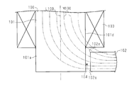
- the magnetic core 100 includes a first core 101 and a second core 102, and the first core 101 has a leg portion 101 a around which the coil 103 is wound,
- the core 102 is assumed to extend outside the coil 103 in a direction along the winding center axis L100 of the coil 103 and in a direction orthogonal to the extending direction of the leg portion 101a.
- a gap 104 is formed between the end portion of the outer surface 101 d facing the coil 103 in the leg portion 101 a and the end surface 102 a of the second core 102.
- the magnetic flux M100 tends to pass through the shortest path of the magnetic core 100 so that the magnetic resistance of the magnetic path formed in the magnetic core 100 becomes low. Therefore, the magnetic flux M100 is concentrated in a peripheral region including the corner portion 102e formed by the end surface 102a of the second core 102 and the end surface near the coil 103. Then, a leakage magnetic flux interlinking the coil 103 located in the vicinity of the corner 102e is generated, and an eddy current is generated in the coil 103 due to the leakage magnetic flux interlinking the coil 103, resulting in Joule loss, and as a reactor or a transformer Will degrade the performance.
- An object of the present invention is to provide an induction device capable of reducing leakage magnetic flux linked to a coil.
- an induction device includes a magnetic core that forms a magnetic path and a coil wound around the magnetic core.
- the magnetic core has a first core and a second core.
- the first core has legs that extend in a direction along the winding center axis of the coil.
- the coil is disposed around the leg.
- the second core extends in a direction intersecting with the extending direction of the legs.
- the leg portion has a gap forming portion provided at a position where the extending direction of the leg portion and the extending direction of the second core intersect.
- the gap forming portion has a facing surface that faces the second core.
- the second core has a gap forming surface that faces the facing surface and forms a gap with the facing surface.
- the opposing surface and the gap forming surface are disposed at a position closer to the axis of the leg than the outer surface of the leg facing the coil.
- (A) is sectional drawing which shows the electronic device in embodiment of this invention
- (b) is a schematic diagram of the induction
- the induction device constitutes a reactor device that is an in-vehicle electronic device.
- the reactor device 10 includes an induction device 11 having a magnetic core 20 that forms a magnetic path and a coil 30 wound around the magnetic core 20.
- the reactor device 10 includes a case 12 as a heat radiating member that houses the induction device 11.
- the case 12 is made of metal (in this embodiment, made of aluminum).
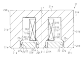
- the magnetic core 20 has a first core 21 and a second core 22.
- the first core 21 is a U-type core
- the second core 22 is an I-type core.
- the first core 21 and the second core 22 are magnetic bodies and are formed of a dust core.
- the first core 21 is formed of a flat plate portion 21a having a substantially rectangular flat plate shape, and a pair of columnar leg portions 21b extending in a direction orthogonal to the flat plate portion 21a from both longitudinal ends of the flat plate portion 21a. Yes.
- a coil element 31 constituting the coil 30 is wound around each leg portion 21b in an annular shape. Therefore, each leg portion 21b extends in the direction along the winding center axis L of each coil element 31, and the coil element 31 is disposed in the periphery.
- the axis of the leg 21 b coincides with the winding center axis L of the coil element 31.
- the coil elements 31 are adjacent to each other with the winding center axes L of the coil elements 31 arranged in parallel to each other.
- Each coil element 31 is formed by edgewise bending a single conductive plate.
- each coil element 31 is connected by the connection part 34 provided in the space
- FIG. The winding directions of the coil elements 31 are different.
- the second core 22 is positioned outside the end of the coil element 31 opposite to the end near the flat plate portion 21a in the direction along the winding center axis L of the coil element 31. It extends in a direction orthogonal to the extending direction of the portion 21b.
- the second core 22 has a flat plate shape extending in parallel with the flat plate portion 21a.
- each leg 21b in the extending direction is longer than the length along the winding center axis L of the coil element 31.
- each leg part 21b has the front-end
- the distal end portion 21 e protrudes outward from the end portion of the coil element 31 opposite to the end portion near the flat plate portion 21 a.
- a recess 23 is formed in a part of the outer surface 21d (outer peripheral surface) facing the coil element 31 in the leg 21b. Both end portions in the extending direction of the second core 22 enter the recess 23, respectively.
- each of the recesses 23 has a facing surface 23a that faces the end surface 22a in the extending direction of the second core 22 and extends in a direction along the axis of the leg portion 21b.
- the facing surface 23a is disposed at a position closer to the axis of the leg 21b than the outer surface 21d of the leg 21b.
- the recessed part 23 has the curved part 23b which connects the opposing surface 23a and the outer surface 21d of the leg part 21b.
- the curved portion 23b is continuous with the opposing surface 23a and is curved in an arc while being separated from the axis of the leg 21b.
- the curved portion 23b is continuous with the first curved portion 231b and extends in a direction along the axis of the leg 21b. It is formed of a second curved portion 232b that is curved in an arc and connected to the outer surface 21d of the leg portion 21b.
- the end surface 22a of the second core 22 is disposed at a position closer to the axis of the leg 21b than the outer surface 21d of the corresponding leg 21b.
- a gap 25 is formed between the facing surface 23 a and the end surface 22 a of the second core 22. Therefore, both end surfaces 22 a of the second core 22 are gap forming surfaces that form the gap 25.
- the tip 21e of the leg 21b is provided at a position where the extending direction of the leg 21b and the extending direction of the second core 22 intersect, and forms a gap 25.
- the tip portion 21e functions as a gap forming portion. Therefore, in this embodiment, the gap formation part is provided integrally with the leg part 21b.
- the gap 25 is disposed at a position closer to the axis of the leg 21b than the outer surface 21d of the leg 21b.
- the gap 25 is an air gap that is an air layer, a non-magnetic material (for example, ceramic) gap plate, or the like.
- a chamfered portion 22 r is formed on the entire outer edge of the end surface 22 a of the second core 22.
- the chamfered portion 22r has a round shape.
- the induction device 11 includes a heat dissipating grease (not shown) in which a tip surface 21g of each leg 21b and a flat surface 22g opposite to the end surface near the coil 30 in the second core 22 are provided. It is arrange
- the magnetic flux M1 tends to pass through the shortest path of the magnetic core 20 so that the magnetic resistance of the magnetic path formed in the magnetic core 20 becomes low. Therefore, the magnetic flux M1 is concentrated in a peripheral region including the corner portion 22e formed by the end surface 22a of the second core 22 and the end surface near the coil 30.
- the opposing surface 23a that forms the gap 25 and the end surface 22a of the second core 22 are disposed closer to the axis of the leg 21b than the outer surface 21d of the leg 21b.
- angular part 22e of the 2nd core 22 is provided. Is separated from the coil 30. As a result, the leakage magnetic flux linked to the coil 30 located near the corner 22e of the second core 22 is reduced.
- the facing surface 23a that forms the gap 25 and the end surface 22a of the second core 22 are disposed closer to the axis of the leg 21b than the outer surface 21d that faces the coil 30 in the leg 21b. According to this, compared with the case where the end surface 22a of the second core 22 is disposed at a position farther from the axis of the leg 21b than the outer surface 21d facing the coil 30 in the leg 21b, The corner 22e formed by the end surface 22a of the two cores 22 and the end surface near the coil 30 can be separated from the coil 30. As a result, the leakage magnetic flux linked to the coil 30 located in the vicinity of the corner portion 22e of the second core 22 can be reduced.
- a chamfered portion 22r is formed on the entire outer edge of the end surface 22a of the second core 22. According to this, since the chamfered portion 22r is formed at the corner 22e formed by the end surface 22a of the second core 22 and the end surface near the coil 30, the chamfered portion 22r is formed at the corner 22e of the second core 22. Compared with the case where it is not, it can suppress that the magnetic flux M1 concentrates on the peripheral area
- the tip 21e of the leg 21b functions as a gap forming part that forms the gap 25. According to this, since the gap forming portion is provided integrally with the leg portion 21b, it is easier to assemble the magnetic core 20 than a configuration in which the gap forming portion is separate from the leg portion 21b. It can be. As a result, the manufacture of the induction device 11 can be simplified.
- the opposing surface 23a and the outer surface 21d of the leg 21b are connected by an orthogonal part extending in a direction orthogonal to the axis of the leg 21b, and between the opposing surface 23a and the orthogonal part, And when a pin angle is formed between the orthogonal part and the outer surface 21d of the leg part 21b, the magnetic flux is easily concentrated on the pin angle. If the pin angle and the second core 22 are close to each other, a leakage magnetic flux is likely to be generated between the pin angle and the second core 22, and this leakage magnetic flux may be linked to the coil 30. is there.
- the 3rd core 40 as a gap formation part may be provided in the position where the extension direction of the leg part 21b and the extension direction of the 2nd core 22 cross
- the third core 40 is an I-type core.
- the third core 40 is a magnetic body and is formed of a dust core.
- the third core 40 is a separate body from the leg portion 21b.
- a gap 41 is formed between the leg 21 b and the third core 40.
- the third core 40 has a facing surface 40 a that faces the end surface 22 a of the second core 22.
- the facing surface 40a is disposed at a position closer to the axis of the leg 21b than the outer surface 21d of the leg 21b.
- a gap 25 is formed between the facing surface 40 a and the end surface 22 a of the second core 22.
- the third core 40 is separate from the leg 21b and the gap 41 can be formed between the leg 21b and the third core 40, the magnetic saturation of the magnetic core 20 can be further suppressed.
- the third core 40 and the leg portion 21b may be in contact with each other.
- the magnetic core 20A may have a first core 21A that is an E-type core.
- the first core 21A includes a columnar leg portion 21B that extends in a direction orthogonal to the flat plate portion 21a from the central portion of the flat plate portion 21a.
- a coil 30A is wound around the leg 21B in an annular shape. The axis of the leg 21B coincides with the winding center axis L of the coil 30A.
- An annular recess 23A extending in the circumferential direction of the leg 21B is formed on the outer peripheral surface of the tip 21E of the leg 21B.
- the distal end portion 21 ⁇ / b> E of the leg portion 21 ⁇ / b> B is inserted into an insertion hole 22 h formed in the central portion of the second core 22.
- the recess 23A has a facing surface 231A that faces the inner peripheral surface 221h of the insertion hole 22h of the second core 22.
- the opposing surface 231A is disposed at a position closer to the axis of the leg 21B than the outer surface 21D of the leg 21B.
- the inner peripheral surface 221h of the insertion hole 22h of the second core 22 is disposed at a position closer to the axis of the leg 21B than the outer surface 21D of the leg 21B.
- An annular gap 25A is formed between the facing surface 231A and the inner peripheral surface 221h of the insertion hole 22h of the second core 22. Therefore, the inner peripheral surface 221h of the insertion hole 22h of the second core 22 is a gap forming surface that forms the gap 25A.
- the tip 21E of the leg 21B is provided at a position where the extending direction of the leg 21B and the extending direction of the second core 22 intersect, and forms a gap 25A.
- the distal end portion 21E functions as a gap forming portion.
- the gap 25A is disposed at a position closer to the axis of the leg 21B than the outer surface 21D of the leg 21B.
- the second core 22 is located outside the end of the coil element 31 opposite to the end near the flat plate portion 21a in the direction along the winding center axis L of the coil element 31. And extending in the direction intersecting with the extending direction of the leg portion 21b.
- each leg 21 b may not be in contact with the case 12, and only the flat surface 22 g of the second core 22 may be in contact with the case 12.
- the opposing surface 23a and the outer surface 21d of the leg 21b may be connected by an orthogonal part that extends in a direction orthogonal to the axis of the leg 21b.
- the facing surface 23a and the outer surface 21d of the leg portion 21b may be connected by an oblique portion that extends in an oblique direction with respect to the axis of the leg portion 21b.
- at least a chamfered portion is formed at the corner 22e formed by the end surface 22a of the second core 22 and the end surface near the coil 30. That is, the chamfered portion may not be formed at the corner portion formed by the end surface 22a of the second core 22 and the end surface near the case 12.
- the chamfered portion may not be formed in the corner portion near the case 12 in the tip portion 21e of each leg portion 21b.
- the shape of the curved portion 23b is not particularly limited.
- the number of cores is not particularly limited.
- the induction device 11 may include three or more coil elements 31.
- the coil element 31 may be a wound round wire.
- the reactor device 10 may be other than a vehicle-mounted device.
Abstract
La présente invention concerne un appareil à induction comprend: un noyau magnétique formant un circuit magnétique; et une bobine. Le noyau magnétique comprend un premier noyau et un deuxième noyau. Le premier noyau est doté d'une partie de branche s'étendant dans la direction de la ligne d'axe central d'enroulement de la bobine. La bobine est disposée autour de la partie de branche. Le deuxième noyau s'étend dans la direction transverse à la direction d'extension de la partie de branche. La partie de branche est dotée d'une section de formation d'écartement disposée dans une position où la direction d'extension de la partie de branche croise la direction d'extension du deuxième noyau. La section de formation d'écartement présente une surface en vis-à-vis qui fait face au deuxième noyau. Le deuxième noyau présente une surface de formation d'écartement qui fait face à la surface en vis-à-vis et forme un écartement conjointement avec la surface en vis-à-vis. La surface en vis-à-vis et la surface de formation d'écartement sont disposées plus près de la ligne d'axe de la partie de branche qu'une surface côté extérieur faisant face à la bobine dans la partie de branche.
Applications Claiming Priority (2)
| Application Number | Priority Date | Filing Date | Title |
|---|---|---|---|
| JP2014-232943 | 2014-11-17 | ||
| JP2014232943A JP6237586B2 (ja) | 2014-11-17 | 2014-11-17 | 誘導機器 |
Publications (1)
| Publication Number | Publication Date |
|---|---|
| WO2016080131A1 true WO2016080131A1 (fr) | 2016-05-26 |
Family
ID=56013688
Family Applications (1)
| Application Number | Title | Priority Date | Filing Date |
|---|---|---|---|
| PCT/JP2015/079468 WO2016080131A1 (fr) | 2014-11-17 | 2015-10-19 | Appareil à induction |
Country Status (2)
| Country | Link |
|---|---|
| JP (1) | JP6237586B2 (fr) |
| WO (1) | WO2016080131A1 (fr) |
Cited By (2)
| Publication number | Priority date | Publication date | Assignee | Title |
|---|---|---|---|---|
| JP2021019003A (ja) * | 2019-07-17 | 2021-02-15 | 三菱電機株式会社 | リアクトル及び電力変換装置 |
| WO2023104377A1 (fr) * | 2021-12-07 | 2023-06-15 | Robert Bosch Gmbh | Ensemble inductif |
Families Citing this family (1)
| Publication number | Priority date | Publication date | Assignee | Title |
|---|---|---|---|---|
| WO2023162509A1 (fr) * | 2022-02-25 | 2023-08-31 | Tdk株式会社 | Composant magnétique et dispositif de conversion de puissance |
Citations (5)
| Publication number | Priority date | Publication date | Assignee | Title |
|---|---|---|---|---|
| US4149136A (en) * | 1976-12-23 | 1979-04-10 | Karl Philberth | Core lamination for shell-type cores, preferably for transformers |
| JPH04206509A (ja) * | 1990-11-30 | 1992-07-28 | Hitachi Ltd | ギャップ付きコア |
| JPH0520310U (ja) * | 1991-08-26 | 1993-03-12 | 松下電工株式会社 | 電磁装置 |
| JP2000182844A (ja) * | 1998-12-18 | 2000-06-30 | Matsushita Electric Ind Co Ltd | インダクタンス部品 |
| WO2014103298A1 (fr) * | 2012-12-27 | 2014-07-03 | 川崎重工業株式会社 | Bobine de réactance |
Family Cites Families (1)
| Publication number | Priority date | Publication date | Assignee | Title |
|---|---|---|---|---|
| KR101241564B1 (ko) * | 2011-08-04 | 2013-03-11 | 전주대학교 산학협력단 | 커플 인덕터, 커플 변압기 및 이를 이용한 커플 인덕터-변압기 |
-
2014
- 2014-11-17 JP JP2014232943A patent/JP6237586B2/ja active Active
-
2015
- 2015-10-19 WO PCT/JP2015/079468 patent/WO2016080131A1/fr active Application Filing
Patent Citations (5)
| Publication number | Priority date | Publication date | Assignee | Title |
|---|---|---|---|---|
| US4149136A (en) * | 1976-12-23 | 1979-04-10 | Karl Philberth | Core lamination for shell-type cores, preferably for transformers |
| JPH04206509A (ja) * | 1990-11-30 | 1992-07-28 | Hitachi Ltd | ギャップ付きコア |
| JPH0520310U (ja) * | 1991-08-26 | 1993-03-12 | 松下電工株式会社 | 電磁装置 |
| JP2000182844A (ja) * | 1998-12-18 | 2000-06-30 | Matsushita Electric Ind Co Ltd | インダクタンス部品 |
| WO2014103298A1 (fr) * | 2012-12-27 | 2014-07-03 | 川崎重工業株式会社 | Bobine de réactance |
Cited By (2)
| Publication number | Priority date | Publication date | Assignee | Title |
|---|---|---|---|---|
| JP2021019003A (ja) * | 2019-07-17 | 2021-02-15 | 三菱電機株式会社 | リアクトル及び電力変換装置 |
| WO2023104377A1 (fr) * | 2021-12-07 | 2023-06-15 | Robert Bosch Gmbh | Ensemble inductif |
Also Published As
| Publication number | Publication date |
|---|---|
| JP6237586B2 (ja) | 2017-11-29 |
| JP2016096312A (ja) | 2016-05-26 |
Similar Documents
| Publication | Publication Date | Title |
|---|---|---|
| JP5333294B2 (ja) | 誘導機器の組立体 | |
| KR20100121644A (ko) | 전원 수신 코일 유닛 | |
| CN103714946B (zh) | 混合磁路磁集成电感器 | |
| WO2016080131A1 (fr) | Appareil à induction | |
| JP2014220435A (ja) | リアクタ | |
| US10102966B2 (en) | Stationary induction apparatus | |
| JP6089824B2 (ja) | トランス | |
| US20160211067A1 (en) | Reactor device and method for manufacturing reactor device | |
| JP5552661B2 (ja) | 誘導機器 | |
| JP6711139B2 (ja) | コイル装置 | |
| JP6064943B2 (ja) | 電子機器 | |
| JP2015133353A (ja) | 誘導機器 | |
| JP2018190781A (ja) | 車両用磁性部品 | |
| US20170178782A1 (en) | Compact inductor | |
| JP2016096312A5 (fr) | ||
| JP2016096315A (ja) | 誘導機器 | |
| JP6495148B2 (ja) | トランス | |
| US9672974B2 (en) | Magnetic component and power transfer device | |
| JP7087083B2 (ja) | 変圧器鉄心および変圧器 | |
| JP2016096313A (ja) | 誘導機器 | |
| JP5516923B2 (ja) | リアクトル、およびコンバータ | |
| JP2016162894A (ja) | 内燃機関用の点火コイル | |
| JP2008218091A (ja) | 誘導加熱装置 | |
| JP2021019104A (ja) | リアクトル装置 | |
| JP2009272438A (ja) | スイッチングトランス |
Legal Events
| Date | Code | Title | Description |
|---|---|---|---|
| 121 | Ep: the epo has been informed by wipo that ep was designated in this application |
Ref document number: 15860540 Country of ref document: EP Kind code of ref document: A1 |
|
| NENP | Non-entry into the national phase |
Ref country code: DE |
|
| 122 | Ep: pct application non-entry in european phase |
Ref document number: 15860540 Country of ref document: EP Kind code of ref document: A1 |