WO2016080131A1 - Induction apparatus - Google Patents
Induction apparatus Download PDFInfo
- Publication number
- WO2016080131A1 WO2016080131A1 PCT/JP2015/079468 JP2015079468W WO2016080131A1 WO 2016080131 A1 WO2016080131 A1 WO 2016080131A1 JP 2015079468 W JP2015079468 W JP 2015079468W WO 2016080131 A1 WO2016080131 A1 WO 2016080131A1
- Authority
- WO
- WIPO (PCT)
- Prior art keywords
- core
- leg
- coil
- gap
- gap forming
- Prior art date
Links
Images


Classifications
-
- H—ELECTRICITY
- H01—ELECTRIC ELEMENTS
- H01F—MAGNETS; INDUCTANCES; TRANSFORMERS; SELECTION OF MATERIALS FOR THEIR MAGNETIC PROPERTIES
- H01F27/00—Details of transformers or inductances, in general
- H01F27/24—Magnetic cores
-
- H—ELECTRICITY
- H01—ELECTRIC ELEMENTS
- H01F—MAGNETS; INDUCTANCES; TRANSFORMERS; SELECTION OF MATERIALS FOR THEIR MAGNETIC PROPERTIES
- H01F37/00—Fixed inductances not covered by group H01F17/00
Definitions
- the present invention relates to an induction device having a magnetic core and a coil wound around the magnetic core.
- An induction device such as a reactor or a transformer has a magnetic core and a coil wound around the magnetic core.
- the current flowing through the coil wound around the magnetic core increases, and the magnetic flux generated by the current flowing through the coil exceeds a certain amount determined by the type of magnetic material forming the magnetic core and the shape and size of the magnetic core.
- the magnetic core is magnetically saturated, and the performance as a reactor or a transformer is lowered. Therefore, by providing a gap in the magnetic flux path (magnetic path) of the magnetic core, the magnetic saturation of the magnetic core is suppressed (see, for example, Patent Document 1).
- the magnetic core 100 includes a first core 101 and a second core 102, and the first core 101 has a leg portion 101 a around which the coil 103 is wound,
- the core 102 is assumed to extend outside the coil 103 in a direction along the winding center axis L100 of the coil 103 and in a direction orthogonal to the extending direction of the leg portion 101a.
- a gap 104 is formed between the end portion of the outer surface 101 d facing the coil 103 in the leg portion 101 a and the end surface 102 a of the second core 102.
- the magnetic flux M100 tends to pass through the shortest path of the magnetic core 100 so that the magnetic resistance of the magnetic path formed in the magnetic core 100 becomes low. Therefore, the magnetic flux M100 is concentrated in a peripheral region including the corner portion 102e formed by the end surface 102a of the second core 102 and the end surface near the coil 103. Then, a leakage magnetic flux interlinking the coil 103 located in the vicinity of the corner 102e is generated, and an eddy current is generated in the coil 103 due to the leakage magnetic flux interlinking the coil 103, resulting in Joule loss, and as a reactor or a transformer Will degrade the performance.
- An object of the present invention is to provide an induction device capable of reducing leakage magnetic flux linked to a coil.
- an induction device includes a magnetic core that forms a magnetic path and a coil wound around the magnetic core.
- the magnetic core has a first core and a second core.
- the first core has legs that extend in a direction along the winding center axis of the coil.
- the coil is disposed around the leg.
- the second core extends in a direction intersecting with the extending direction of the legs.
- the leg portion has a gap forming portion provided at a position where the extending direction of the leg portion and the extending direction of the second core intersect.
- the gap forming portion has a facing surface that faces the second core.
- the second core has a gap forming surface that faces the facing surface and forms a gap with the facing surface.
- the opposing surface and the gap forming surface are disposed at a position closer to the axis of the leg than the outer surface of the leg facing the coil.
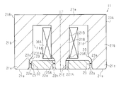
- (A) is sectional drawing which shows the electronic device in embodiment of this invention
- (b) is a schematic diagram of the induction
- the induction device constitutes a reactor device that is an in-vehicle electronic device.
- the reactor device 10 includes an induction device 11 having a magnetic core 20 that forms a magnetic path and a coil 30 wound around the magnetic core 20.
- the reactor device 10 includes a case 12 as a heat radiating member that houses the induction device 11.
- the case 12 is made of metal (in this embodiment, made of aluminum).
- the magnetic core 20 has a first core 21 and a second core 22.
- the first core 21 is a U-type core
- the second core 22 is an I-type core.
- the first core 21 and the second core 22 are magnetic bodies and are formed of a dust core.
- the first core 21 is formed of a flat plate portion 21a having a substantially rectangular flat plate shape, and a pair of columnar leg portions 21b extending in a direction orthogonal to the flat plate portion 21a from both longitudinal ends of the flat plate portion 21a. Yes.
- a coil element 31 constituting the coil 30 is wound around each leg portion 21b in an annular shape. Therefore, each leg portion 21b extends in the direction along the winding center axis L of each coil element 31, and the coil element 31 is disposed in the periphery.
- the axis of the leg 21 b coincides with the winding center axis L of the coil element 31.
- the coil elements 31 are adjacent to each other with the winding center axes L of the coil elements 31 arranged in parallel to each other.
- Each coil element 31 is formed by edgewise bending a single conductive plate.
- each coil element 31 is connected by the connection part 34 provided in the space
- FIG. The winding directions of the coil elements 31 are different.
- the second core 22 is positioned outside the end of the coil element 31 opposite to the end near the flat plate portion 21a in the direction along the winding center axis L of the coil element 31. It extends in a direction orthogonal to the extending direction of the portion 21b.
- the second core 22 has a flat plate shape extending in parallel with the flat plate portion 21a.
- each leg 21b in the extending direction is longer than the length along the winding center axis L of the coil element 31.
- each leg part 21b has the front-end
- the distal end portion 21 e protrudes outward from the end portion of the coil element 31 opposite to the end portion near the flat plate portion 21 a.
- a recess 23 is formed in a part of the outer surface 21d (outer peripheral surface) facing the coil element 31 in the leg 21b. Both end portions in the extending direction of the second core 22 enter the recess 23, respectively.
- each of the recesses 23 has a facing surface 23a that faces the end surface 22a in the extending direction of the second core 22 and extends in a direction along the axis of the leg portion 21b.
- the facing surface 23a is disposed at a position closer to the axis of the leg 21b than the outer surface 21d of the leg 21b.
- the recessed part 23 has the curved part 23b which connects the opposing surface 23a and the outer surface 21d of the leg part 21b.
- the curved portion 23b is continuous with the opposing surface 23a and is curved in an arc while being separated from the axis of the leg 21b.
- the curved portion 23b is continuous with the first curved portion 231b and extends in a direction along the axis of the leg 21b. It is formed of a second curved portion 232b that is curved in an arc and connected to the outer surface 21d of the leg portion 21b.
- the end surface 22a of the second core 22 is disposed at a position closer to the axis of the leg 21b than the outer surface 21d of the corresponding leg 21b.
- a gap 25 is formed between the facing surface 23 a and the end surface 22 a of the second core 22. Therefore, both end surfaces 22 a of the second core 22 are gap forming surfaces that form the gap 25.
- the tip 21e of the leg 21b is provided at a position where the extending direction of the leg 21b and the extending direction of the second core 22 intersect, and forms a gap 25.
- the tip portion 21e functions as a gap forming portion. Therefore, in this embodiment, the gap formation part is provided integrally with the leg part 21b.
- the gap 25 is disposed at a position closer to the axis of the leg 21b than the outer surface 21d of the leg 21b.
- the gap 25 is an air gap that is an air layer, a non-magnetic material (for example, ceramic) gap plate, or the like.
- a chamfered portion 22 r is formed on the entire outer edge of the end surface 22 a of the second core 22.
- the chamfered portion 22r has a round shape.
- the induction device 11 includes a heat dissipating grease (not shown) in which a tip surface 21g of each leg 21b and a flat surface 22g opposite to the end surface near the coil 30 in the second core 22 are provided. It is arrange
- the magnetic flux M1 tends to pass through the shortest path of the magnetic core 20 so that the magnetic resistance of the magnetic path formed in the magnetic core 20 becomes low. Therefore, the magnetic flux M1 is concentrated in a peripheral region including the corner portion 22e formed by the end surface 22a of the second core 22 and the end surface near the coil 30.
- the opposing surface 23a that forms the gap 25 and the end surface 22a of the second core 22 are disposed closer to the axis of the leg 21b than the outer surface 21d of the leg 21b.
- angular part 22e of the 2nd core 22 is provided. Is separated from the coil 30. As a result, the leakage magnetic flux linked to the coil 30 located near the corner 22e of the second core 22 is reduced.
- the facing surface 23a that forms the gap 25 and the end surface 22a of the second core 22 are disposed closer to the axis of the leg 21b than the outer surface 21d that faces the coil 30 in the leg 21b. According to this, compared with the case where the end surface 22a of the second core 22 is disposed at a position farther from the axis of the leg 21b than the outer surface 21d facing the coil 30 in the leg 21b, The corner 22e formed by the end surface 22a of the two cores 22 and the end surface near the coil 30 can be separated from the coil 30. As a result, the leakage magnetic flux linked to the coil 30 located in the vicinity of the corner portion 22e of the second core 22 can be reduced.
- a chamfered portion 22r is formed on the entire outer edge of the end surface 22a of the second core 22. According to this, since the chamfered portion 22r is formed at the corner 22e formed by the end surface 22a of the second core 22 and the end surface near the coil 30, the chamfered portion 22r is formed at the corner 22e of the second core 22. Compared with the case where it is not, it can suppress that the magnetic flux M1 concentrates on the peripheral area
- the tip 21e of the leg 21b functions as a gap forming part that forms the gap 25. According to this, since the gap forming portion is provided integrally with the leg portion 21b, it is easier to assemble the magnetic core 20 than a configuration in which the gap forming portion is separate from the leg portion 21b. It can be. As a result, the manufacture of the induction device 11 can be simplified.
- the opposing surface 23a and the outer surface 21d of the leg 21b are connected by an orthogonal part extending in a direction orthogonal to the axis of the leg 21b, and between the opposing surface 23a and the orthogonal part, And when a pin angle is formed between the orthogonal part and the outer surface 21d of the leg part 21b, the magnetic flux is easily concentrated on the pin angle. If the pin angle and the second core 22 are close to each other, a leakage magnetic flux is likely to be generated between the pin angle and the second core 22, and this leakage magnetic flux may be linked to the coil 30. is there.
- the 3rd core 40 as a gap formation part may be provided in the position where the extension direction of the leg part 21b and the extension direction of the 2nd core 22 cross
- the third core 40 is an I-type core.
- the third core 40 is a magnetic body and is formed of a dust core.
- the third core 40 is a separate body from the leg portion 21b.
- a gap 41 is formed between the leg 21 b and the third core 40.
- the third core 40 has a facing surface 40 a that faces the end surface 22 a of the second core 22.
- the facing surface 40a is disposed at a position closer to the axis of the leg 21b than the outer surface 21d of the leg 21b.
- a gap 25 is formed between the facing surface 40 a and the end surface 22 a of the second core 22.
- the third core 40 is separate from the leg 21b and the gap 41 can be formed between the leg 21b and the third core 40, the magnetic saturation of the magnetic core 20 can be further suppressed.
- the third core 40 and the leg portion 21b may be in contact with each other.
- the magnetic core 20A may have a first core 21A that is an E-type core.
- the first core 21A includes a columnar leg portion 21B that extends in a direction orthogonal to the flat plate portion 21a from the central portion of the flat plate portion 21a.
- a coil 30A is wound around the leg 21B in an annular shape. The axis of the leg 21B coincides with the winding center axis L of the coil 30A.
- An annular recess 23A extending in the circumferential direction of the leg 21B is formed on the outer peripheral surface of the tip 21E of the leg 21B.
- the distal end portion 21 ⁇ / b> E of the leg portion 21 ⁇ / b> B is inserted into an insertion hole 22 h formed in the central portion of the second core 22.
- the recess 23A has a facing surface 231A that faces the inner peripheral surface 221h of the insertion hole 22h of the second core 22.
- the opposing surface 231A is disposed at a position closer to the axis of the leg 21B than the outer surface 21D of the leg 21B.
- the inner peripheral surface 221h of the insertion hole 22h of the second core 22 is disposed at a position closer to the axis of the leg 21B than the outer surface 21D of the leg 21B.
- An annular gap 25A is formed between the facing surface 231A and the inner peripheral surface 221h of the insertion hole 22h of the second core 22. Therefore, the inner peripheral surface 221h of the insertion hole 22h of the second core 22 is a gap forming surface that forms the gap 25A.
- the tip 21E of the leg 21B is provided at a position where the extending direction of the leg 21B and the extending direction of the second core 22 intersect, and forms a gap 25A.
- the distal end portion 21E functions as a gap forming portion.
- the gap 25A is disposed at a position closer to the axis of the leg 21B than the outer surface 21D of the leg 21B.
- the second core 22 is located outside the end of the coil element 31 opposite to the end near the flat plate portion 21a in the direction along the winding center axis L of the coil element 31. And extending in the direction intersecting with the extending direction of the leg portion 21b.
- each leg 21 b may not be in contact with the case 12, and only the flat surface 22 g of the second core 22 may be in contact with the case 12.
- the opposing surface 23a and the outer surface 21d of the leg 21b may be connected by an orthogonal part that extends in a direction orthogonal to the axis of the leg 21b.
- the facing surface 23a and the outer surface 21d of the leg portion 21b may be connected by an oblique portion that extends in an oblique direction with respect to the axis of the leg portion 21b.
- at least a chamfered portion is formed at the corner 22e formed by the end surface 22a of the second core 22 and the end surface near the coil 30. That is, the chamfered portion may not be formed at the corner portion formed by the end surface 22a of the second core 22 and the end surface near the case 12.
- the chamfered portion may not be formed in the corner portion near the case 12 in the tip portion 21e of each leg portion 21b.
- the shape of the curved portion 23b is not particularly limited.
- the number of cores is not particularly limited.
- the induction device 11 may include three or more coil elements 31.
- the coil element 31 may be a wound round wire.
- the reactor device 10 may be other than a vehicle-mounted device.
Abstract
This induction apparatus includes: a magnetic core forming a magnetic path; and a coil. The magnetic core has a first core and a second core. The first core has a leg part extending in the direction along the winding central axis line of the coil. The coil is disposed around the leg part. The second core extends in the direction crossing the extension direction of the leg part. The leg part has a gap forming section disposed at a position at which the extension direction of the leg part crosses the extension direction of the second core. The gap forming section has a facing surface which faces the second core. The second core has a gap forming surface which faces the facing surface and forms a gap together with the facing surface. The facing surface and the gap forming surface are disposed more adjacent to the axis line of the leg part than an outer side surface facing the coil in the leg part.
Description
本発明は、磁性コアと、磁性コアに捲回されたコイルとを有する誘導機器に関する。
The present invention relates to an induction device having a magnetic core and a coil wound around the magnetic core.
リアクトルやトランス等の誘導機器は、磁性コアと、磁性コアに捲回されたコイルとを有する。磁性コアに捲回されたコイルに流れる電流が大きくなり、コイルに流れる電流により発生する磁束が、磁性コアをなす磁性体の種類及び磁性コアの形状、大きさ等によって決まるある一定の量を越える場合がある。このような場合、一般的に、磁性コアは磁気飽和し、リアクトルやトランスとしての性能が低下してしまう。そのため、磁性コアの磁束経路(磁路)中にギャップを設けることで、磁性コアが磁気飽和してしまうことを抑制している(例えば特許文献1参照)。
An induction device such as a reactor or a transformer has a magnetic core and a coil wound around the magnetic core. The current flowing through the coil wound around the magnetic core increases, and the magnetic flux generated by the current flowing through the coil exceeds a certain amount determined by the type of magnetic material forming the magnetic core and the shape and size of the magnetic core. There is a case. In such a case, generally, the magnetic core is magnetically saturated, and the performance as a reactor or a transformer is lowered. Therefore, by providing a gap in the magnetic flux path (magnetic path) of the magnetic core, the magnetic saturation of the magnetic core is suppressed (see, for example, Patent Document 1).
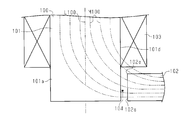
ところで、図4に示すように、磁性コア100は、第1コア101及び第2コア102を含み、第1コア101は、コイル103が周囲に捲回される脚部101aを有し、第2コア102は、コイル103の捲回中心軸線L100に沿った方向におけるコイル103よりも外側で、脚部101aの延設方向に対して直交する方向に延びているとする。そして、脚部101aにおけるコイル103と対向する外側面101dの端部と、第2コア102の端面102aとの間にギャップ104が形成されているとする。
Incidentally, as shown in FIG. 4, the magnetic core 100 includes a first core 101 and a second core 102, and the first core 101 has a leg portion 101 a around which the coil 103 is wound, The core 102 is assumed to extend outside the coil 103 in a direction along the winding center axis L100 of the coil 103 and in a direction orthogonal to the extending direction of the leg portion 101a. Then, it is assumed that a gap 104 is formed between the end portion of the outer surface 101 d facing the coil 103 in the leg portion 101 a and the end surface 102 a of the second core 102.
この場合、磁束M100は、磁性コア100に形成される磁路の磁気抵抗が低くなるように、磁性コア100の最短経路を通過しようとする。そのため、磁束M100は、第2コア102における端面102aとコイル103寄りの端面とがなす角部102eを含む周辺の領域に集中する。すると、角部102eの近傍に位置するコイル103を鎖交する漏れ磁束が発生し、コイル103を鎖交する漏れ磁束によりコイル103中に渦電流が発生するためジュール損が生じ、リアクトルやトランスとしての性能が低下してしまう。
In this case, the magnetic flux M100 tends to pass through the shortest path of the magnetic core 100 so that the magnetic resistance of the magnetic path formed in the magnetic core 100 becomes low. Therefore, the magnetic flux M100 is concentrated in a peripheral region including the corner portion 102e formed by the end surface 102a of the second core 102 and the end surface near the coil 103. Then, a leakage magnetic flux interlinking the coil 103 located in the vicinity of the corner 102e is generated, and an eddy current is generated in the coil 103 due to the leakage magnetic flux interlinking the coil 103, resulting in Joule loss, and as a reactor or a transformer Will degrade the performance.
本発明の目的は、コイルに鎖交する漏れ磁束を低減することができる誘導機器を提供することにある。
An object of the present invention is to provide an induction device capable of reducing leakage magnetic flux linked to a coil.
上記目的を達成するため、本発明の一態様にかかる誘導機器は、磁路を形成する磁性コアと、前記磁性コアに捲回されるコイルと、を含んでいる。前記磁性コアは、第1コアと第2コアとを有している。前記第1コアは、前記コイルの捲回中心軸線に沿った方向に延びる脚部を有している。前記コイルは、前記脚部の周囲に配置されている。前記第2コアは、前記脚部の延設方向に対して交差する方向に延びている。前記脚部は、該脚部の延設方向と前記第2コアの延設方向とが交差する位置に設けられたギャップ形成部を有している。前記ギャップ形成部は、前記第2コアに対向する対向面を有している。前記第2コアは、前記対向面に対向して前記対向面と共にギャップを形成するギャップ形成面を有している。前記対向面及び前記ギャップ形成面は、前記脚部における前記コイルと対向する外側面よりも前記脚部の軸線に近い位置に配置されている。
In order to achieve the above object, an induction device according to an aspect of the present invention includes a magnetic core that forms a magnetic path and a coil wound around the magnetic core. The magnetic core has a first core and a second core. The first core has legs that extend in a direction along the winding center axis of the coil. The coil is disposed around the leg. The second core extends in a direction intersecting with the extending direction of the legs. The leg portion has a gap forming portion provided at a position where the extending direction of the leg portion and the extending direction of the second core intersect. The gap forming portion has a facing surface that faces the second core. The second core has a gap forming surface that faces the facing surface and forms a gap with the facing surface. The opposing surface and the gap forming surface are disposed at a position closer to the axis of the leg than the outer surface of the leg facing the coil.
以下、誘導機器を具体化した一実施形態を図1にしたがって説明する。本実施形態の誘導機器は、車載用の電子機器であるリアクトル装置を構成している。
図1(a)に示すように、リアクトル装置10は、磁路を形成する磁性コア20と、磁性コア20に捲回されるコイル30とを有する誘導機器11を備えている。また、リアクトル装置10は、誘導機器11を収容する放熱部材としてのケース12を備えている。ケース12は金属製(本実施形態ではアルミニウム製)である。 Hereinafter, an embodiment embodying a guidance device will be described with reference to FIG. The induction device according to the present embodiment constitutes a reactor device that is an in-vehicle electronic device.
As shown in FIG. 1A, thereactor device 10 includes an induction device 11 having a magnetic core 20 that forms a magnetic path and a coil 30 wound around the magnetic core 20. Further, the reactor device 10 includes a case 12 as a heat radiating member that houses the induction device 11. The case 12 is made of metal (in this embodiment, made of aluminum).
図1(a)に示すように、リアクトル装置10は、磁路を形成する磁性コア20と、磁性コア20に捲回されるコイル30とを有する誘導機器11を備えている。また、リアクトル装置10は、誘導機器11を収容する放熱部材としてのケース12を備えている。ケース12は金属製(本実施形態ではアルミニウム製)である。 Hereinafter, an embodiment embodying a guidance device will be described with reference to FIG. The induction device according to the present embodiment constitutes a reactor device that is an in-vehicle electronic device.
As shown in FIG. 1A, the
磁性コア20は、第1コア21及び第2コア22を有する。第1コア21はU型コアであるとともに、第2コア22はI型コアである。第1コア21及び第2コア22は磁性体であるとともに、圧粉磁芯により形成されている。
The magnetic core 20 has a first core 21 and a second core 22. The first core 21 is a U-type core, and the second core 22 is an I-type core. The first core 21 and the second core 22 are magnetic bodies and are formed of a dust core.
第1コア21は、略矩形平板状をなす平板部21aと、平板部21aの長手方向の両端から平板部21aに対して直交する方向に延びる円柱状の一対の脚部21bとから形成されている。各脚部21bの周囲には、コイル30を構成するコイル要素31がそれぞれ環状に捲回されている。よって、各脚部21bは、各コイル要素31の捲回中心軸線Lに沿った方向に延びるとともに周囲にコイル要素31が配置されている。なお、本実施形態では、脚部21bの軸線は、コイル要素31の捲回中心軸線Lと一致している。
The first core 21 is formed of a flat plate portion 21a having a substantially rectangular flat plate shape, and a pair of columnar leg portions 21b extending in a direction orthogonal to the flat plate portion 21a from both longitudinal ends of the flat plate portion 21a. Yes. A coil element 31 constituting the coil 30 is wound around each leg portion 21b in an annular shape. Therefore, each leg portion 21b extends in the direction along the winding center axis L of each coil element 31, and the coil element 31 is disposed in the periphery. In the present embodiment, the axis of the leg 21 b coincides with the winding center axis L of the coil element 31.
コイル要素31は、コイル要素31の捲回中心軸線Lが互いに平行に配置されて隣り合っている。各コイル要素31は、一本の導電板をエッジワイズ曲げして形成されている。そして、コイル要素31が隣り合って形成される空隙33に設けられる連結部34によって、各コイル要素31同士が連結されている。コイル要素31の捲回方向はそれぞれ異なっている。
The coil elements 31 are adjacent to each other with the winding center axes L of the coil elements 31 arranged in parallel to each other. Each coil element 31 is formed by edgewise bending a single conductive plate. And each coil element 31 is connected by the connection part 34 provided in the space | gap 33 formed adjacent to the coil element 31. FIG. The winding directions of the coil elements 31 are different.
第2コア22は、コイル要素31の捲回中心軸線Lに沿った方向において、コイル要素31における平板部21aと寄りの端部とは反対側の端部よりも外側に位置しており、脚部21bの延設方向に対して直交する方向に延びている。第2コア22は、平板部21aと平行に延びる平板状である。
The second core 22 is positioned outside the end of the coil element 31 opposite to the end near the flat plate portion 21a in the direction along the winding center axis L of the coil element 31. It extends in a direction orthogonal to the extending direction of the portion 21b. The second core 22 has a flat plate shape extending in parallel with the flat plate portion 21a.
各脚部21bにおける延設方向の長さは、コイル要素31における捲回中心軸線Lに沿った長さよりも長くなっている。そして、各脚部21bは、平板部21a寄りの端部とは反対側の端部である先端部21eを有している。先端部21eは、捲回中心軸線Lに沿った方向において、コイル要素31における平板部21a寄りの端部とは反対側の端部よりも外側に突出している。
The length of each leg 21b in the extending direction is longer than the length along the winding center axis L of the coil element 31. And each leg part 21b has the front-end | tip part 21e which is an edge part on the opposite side to the edge part near the flat plate part 21a. In the direction along the winding center axis L, the distal end portion 21 e protrudes outward from the end portion of the coil element 31 opposite to the end portion near the flat plate portion 21 a.
各脚部21bの先端部21eにおいて、脚部21bにおけるコイル要素31と対向する外側面21d(外周面)の一部には、凹部23が形成されている。第2コア22の延設方向の両端部は、凹部23内にそれぞれ入り込んでいる。
At the tip 21e of each leg 21b, a recess 23 is formed in a part of the outer surface 21d (outer peripheral surface) facing the coil element 31 in the leg 21b. Both end portions in the extending direction of the second core 22 enter the recess 23, respectively.
図1(b)に示すように、凹部23の各々は、第2コア22の延設方向の端面22aと対向するとともに脚部21bの軸線に沿う方向に延びる対向面23aを有する。対向面23aは、脚部21bの外側面21dよりも脚部21bの軸線に近い位置に配置されている。また、凹部23は、対向面23aと脚部21bの外側面21dとを繋ぐ湾曲部23bを有する。湾曲部23bは、対向面23aに連なるとともに脚部21bの軸線から離間しながら弧状に湾曲する第1湾曲部231bと、第1湾曲部231bに連なるとともに脚部21bの軸線に沿う方向に向けて弧状に湾曲して脚部21bの外側面21dに接続される第2湾曲部232bとから形成されている。
As shown in FIG. 1B, each of the recesses 23 has a facing surface 23a that faces the end surface 22a in the extending direction of the second core 22 and extends in a direction along the axis of the leg portion 21b. The facing surface 23a is disposed at a position closer to the axis of the leg 21b than the outer surface 21d of the leg 21b. Moreover, the recessed part 23 has the curved part 23b which connects the opposing surface 23a and the outer surface 21d of the leg part 21b. The curved portion 23b is continuous with the opposing surface 23a and is curved in an arc while being separated from the axis of the leg 21b. The curved portion 23b is continuous with the first curved portion 231b and extends in a direction along the axis of the leg 21b. It is formed of a second curved portion 232b that is curved in an arc and connected to the outer surface 21d of the leg portion 21b.
第2コア22の端面22aは、対応する脚部21bの外側面21dよりも脚部21bの軸線に近い位置に配置されている。そして、対向面23aと第2コア22の端面22aとの間には、ギャップ25が形成されている。よって、第2コア22の両端面22aは、ギャップ25を形成するギャップ形成面である。さらに、脚部21bの先端部21eは、脚部21bの延設方向と第2コア22の延設方向とが交差する位置に設けられるとともにギャップ25を形成する。先端部21eはギャップ形成部として機能している。よって、本実施形態では、ギャップ形成部は、脚部21bと一体的に設けられている。
The end surface 22a of the second core 22 is disposed at a position closer to the axis of the leg 21b than the outer surface 21d of the corresponding leg 21b. A gap 25 is formed between the facing surface 23 a and the end surface 22 a of the second core 22. Therefore, both end surfaces 22 a of the second core 22 are gap forming surfaces that form the gap 25. Further, the tip 21e of the leg 21b is provided at a position where the extending direction of the leg 21b and the extending direction of the second core 22 intersect, and forms a gap 25. The tip portion 21e functions as a gap forming portion. Therefore, in this embodiment, the gap formation part is provided integrally with the leg part 21b.
ギャップ25は、脚部21bの外側面21dよりも脚部21bの軸線に近い位置に配置されている。なお、ギャップ25は、空気層であるエアギャップや、非磁性体(例えばセラミック)のギャップ板等である。第2コア22における端面22aの外縁全周には、面取り部22rが形成されている。面取り部22rはアール形状である。
The gap 25 is disposed at a position closer to the axis of the leg 21b than the outer surface 21d of the leg 21b. The gap 25 is an air gap that is an air layer, a non-magnetic material (for example, ceramic) gap plate, or the like. A chamfered portion 22 r is formed on the entire outer edge of the end surface 22 a of the second core 22. The chamfered portion 22r has a round shape.
図1(a)に示すように、誘導機器11は、各脚部21bの先端面21gと、第2コア22におけるコイル30寄りの端面とは反対側の平坦面22gとが、図示しない放熱グリースを介してケース12に面接触して密着した状態で、ケース12に配置されている。よって、各脚部21bの先端面21g、及び第2コア22の平坦面22gは、ケース12に接する接触部として機能する。
As shown in FIG. 1 (a), the induction device 11 includes a heat dissipating grease (not shown) in which a tip surface 21g of each leg 21b and a flat surface 22g opposite to the end surface near the coil 30 in the second core 22 are provided. It is arrange | positioned in case 12 in the state which contacted and adhered to case 12 via. Therefore, the front end surface 21 g of each leg portion 21 b and the flat surface 22 g of the second core 22 function as a contact portion in contact with the case 12.
次に、本実施形態の作用を説明する。
図1(b)に示すように、磁束M1は、磁性コア20に形成される磁路の磁気抵抗が低くなるように、磁性コア20の最短経路を通過しようとする。そのため、磁束M1は、第2コア22における端面22aとコイル30寄りの端面とがなす角部22eを含む周辺の領域に集中する。ここで、ギャップ25を形成する対向面23a及び第2コア22の端面22aは、脚部21bの外側面21dよりも脚部21bの軸線に近い位置に配置されている。このため、第2コア22の端面22aが、脚部21bの外側面21dよりも脚部21bの軸線に対して離れた位置に配置されている場合に比べると、第2コア22の角部22eが、コイル30から離間する。その結果、第2コア22の角部22eの近傍に位置するコイル30に鎖交する漏れ磁束が低減される。 Next, the operation of this embodiment will be described.
As shown in FIG. 1B, the magnetic flux M1 tends to pass through the shortest path of themagnetic core 20 so that the magnetic resistance of the magnetic path formed in the magnetic core 20 becomes low. Therefore, the magnetic flux M1 is concentrated in a peripheral region including the corner portion 22e formed by the end surface 22a of the second core 22 and the end surface near the coil 30. Here, the opposing surface 23a that forms the gap 25 and the end surface 22a of the second core 22 are disposed closer to the axis of the leg 21b than the outer surface 21d of the leg 21b. For this reason, compared with the case where the end surface 22a of the 2nd core 22 is arrange | positioned with respect to the axis line of the leg part 21b rather than the outer side surface 21d of the leg part 21b, the corner | angular part 22e of the 2nd core 22 is provided. Is separated from the coil 30. As a result, the leakage magnetic flux linked to the coil 30 located near the corner 22e of the second core 22 is reduced.
図1(b)に示すように、磁束M1は、磁性コア20に形成される磁路の磁気抵抗が低くなるように、磁性コア20の最短経路を通過しようとする。そのため、磁束M1は、第2コア22における端面22aとコイル30寄りの端面とがなす角部22eを含む周辺の領域に集中する。ここで、ギャップ25を形成する対向面23a及び第2コア22の端面22aは、脚部21bの外側面21dよりも脚部21bの軸線に近い位置に配置されている。このため、第2コア22の端面22aが、脚部21bの外側面21dよりも脚部21bの軸線に対して離れた位置に配置されている場合に比べると、第2コア22の角部22eが、コイル30から離間する。その結果、第2コア22の角部22eの近傍に位置するコイル30に鎖交する漏れ磁束が低減される。 Next, the operation of this embodiment will be described.
As shown in FIG. 1B, the magnetic flux M1 tends to pass through the shortest path of the
上記実施形態では以下の利点を得ることができる。
(1)ギャップ25を形成する対向面23a及び第2コア22の端面22aが、脚部21bにおけるコイル30と対向する外側面21dよりも脚部21bの軸線に近い位置に配置されている。これによれば、第2コア22の端面22aが、脚部21bにおけるコイル30と対向する外側面21dよりも脚部21bの軸線に対して離れた位置に配置されている場合に比べると、第2コア22における端面22aとコイル30寄りの端面とがなす角部22eを、コイル30から離間させることができる。その結果、第2コア22の角部22eの近傍に位置するコイル30に鎖交する漏れ磁束を低減することができる。 In the above embodiment, the following advantages can be obtained.
(1) The facing surface 23a that forms thegap 25 and the end surface 22a of the second core 22 are disposed closer to the axis of the leg 21b than the outer surface 21d that faces the coil 30 in the leg 21b. According to this, compared with the case where the end surface 22a of the second core 22 is disposed at a position farther from the axis of the leg 21b than the outer surface 21d facing the coil 30 in the leg 21b, The corner 22e formed by the end surface 22a of the two cores 22 and the end surface near the coil 30 can be separated from the coil 30. As a result, the leakage magnetic flux linked to the coil 30 located in the vicinity of the corner portion 22e of the second core 22 can be reduced.
(1)ギャップ25を形成する対向面23a及び第2コア22の端面22aが、脚部21bにおけるコイル30と対向する外側面21dよりも脚部21bの軸線に近い位置に配置されている。これによれば、第2コア22の端面22aが、脚部21bにおけるコイル30と対向する外側面21dよりも脚部21bの軸線に対して離れた位置に配置されている場合に比べると、第2コア22における端面22aとコイル30寄りの端面とがなす角部22eを、コイル30から離間させることができる。その結果、第2コア22の角部22eの近傍に位置するコイル30に鎖交する漏れ磁束を低減することができる。 In the above embodiment, the following advantages can be obtained.
(1) The facing surface 23a that forms the
(2)第2コア22における端面22aの外縁全周に面取り部22rが形成されている。これによれば、第2コア22における端面22aとコイル30寄りの端面とがなす角部22eに面取り部22rが形成されているため、第2コア22の角部22eに面取り部22rが形成されていない場合に比べると、第2コア22の角部22eを含む周辺の領域に磁束M1が集中してしまうことを抑制することができる。その結果、第2コア22の角部22eの近傍に位置するコイル30に鎖交する漏れ磁束をさらに低減させ易くすることができる。
(2) A chamfered portion 22r is formed on the entire outer edge of the end surface 22a of the second core 22. According to this, since the chamfered portion 22r is formed at the corner 22e formed by the end surface 22a of the second core 22 and the end surface near the coil 30, the chamfered portion 22r is formed at the corner 22e of the second core 22. Compared with the case where it is not, it can suppress that the magnetic flux M1 concentrates on the peripheral area | region including the corner | angular part 22e of the 2nd core 22. FIG. As a result, the leakage magnetic flux interlinking with the coil 30 located in the vicinity of the corner portion 22e of the second core 22 can be further easily reduced.
(3)脚部21bの先端部21eは、ギャップ25を形成するギャップ形成部として機能している。これによれば、ギャップ形成部が脚部21bと一体的に設けられているため、ギャップ形成部が脚部21bとは別体である構成に比べると、磁性コア20の組み立て作業を容易なものとすることができる。その結果、誘導機器11の製造を簡素化させることができる。
(3) The tip 21e of the leg 21b functions as a gap forming part that forms the gap 25. According to this, since the gap forming portion is provided integrally with the leg portion 21b, it is easier to assemble the magnetic core 20 than a configuration in which the gap forming portion is separate from the leg portion 21b. It can be. As a result, the manufacture of the induction device 11 can be simplified.
(4)例えば、対向面23aと脚部21bの外側面21dとが、脚部21bの軸線に対して直交する方向に延びる直交部によって接続されており、対向面23aと直交部との間、及び直交部と脚部21bの外側面21dとの間にピン角が形成されている場合、ピン角に磁束が集中し易くなる。そして、ピン角と第2コア22とが近接していると、ピン角と第2コア22との間で漏れ磁束が発生し易くなり、この漏れ磁束がコイル30に鎖交してしまう虞がある。しかし、第1湾曲部231b及び第2湾曲部232bには、ピン角に比べて磁束が集中し難いため、第1湾曲部231b及び第2湾曲部232bと第2コア22との間で漏れ磁束が生じ難くなり、コイル30に鎖交する漏れ磁束を低減することができる。
(4) For example, the opposing surface 23a and the outer surface 21d of the leg 21b are connected by an orthogonal part extending in a direction orthogonal to the axis of the leg 21b, and between the opposing surface 23a and the orthogonal part, And when a pin angle is formed between the orthogonal part and the outer surface 21d of the leg part 21b, the magnetic flux is easily concentrated on the pin angle. If the pin angle and the second core 22 are close to each other, a leakage magnetic flux is likely to be generated between the pin angle and the second core 22, and this leakage magnetic flux may be linked to the coil 30. is there. However, since it is difficult for the magnetic flux to concentrate on the first bending portion 231b and the second bending portion 232b as compared to the pin angle, the leakage magnetic flux between the first bending portion 231b and the second bending portion 232b and the second core 22. Is less likely to occur, and the leakage magnetic flux linked to the coil 30 can be reduced.
(5)各脚部21bの先端面21gと、第2コア22の平坦面22gとは、ケース12に接する。これによれば、第1コア21から生じる熱が各脚部21bの先端部21eを介してケース12に放熱されるとともに、第2コア22から生じる熱はケース12によって放熱されるため、磁性コア20全体の放熱性能を向上させることができる。
(5) The tip surface 21g of each leg 21b and the flat surface 22g of the second core 22 are in contact with the case 12. According to this, since the heat generated from the first core 21 is radiated to the case 12 via the tip 21e of each leg 21b, and the heat generated from the second core 22 is radiated by the case 12, the magnetic core The heat radiation performance of the entire 20 can be improved.
なお、上記実施形態は以下のように変更してもよい。
○ 図2に示すように、脚部21bの延設方向と第2コア22の延設方向とが交差する位置に、ギャップ形成部としての第3コア40が設けられていてもよい。第3コア40はI型コアである。第3コア40は磁性体であるとともに、圧粉磁芯により形成されている。第3コア40は、脚部21bとは別体である。そして、脚部21bと第3コア40との間にはギャップ41が形成されている。第3コア40は、第2コア22の端面22aと対向する対向面40aを有する。対向面40aは、脚部21bの外側面21dよりも脚部21bの軸線に近い位置に配置されている。そして、対向面40aと第2コア22の端面22aとの間には、ギャップ25が形成されている。 In addition, you may change the said embodiment as follows.
As shown in FIG. 2, the3rd core 40 as a gap formation part may be provided in the position where the extension direction of the leg part 21b and the extension direction of the 2nd core 22 cross | intersect. The third core 40 is an I-type core. The third core 40 is a magnetic body and is formed of a dust core. The third core 40 is a separate body from the leg portion 21b. A gap 41 is formed between the leg 21 b and the third core 40. The third core 40 has a facing surface 40 a that faces the end surface 22 a of the second core 22. The facing surface 40a is disposed at a position closer to the axis of the leg 21b than the outer surface 21d of the leg 21b. A gap 25 is formed between the facing surface 40 a and the end surface 22 a of the second core 22.
○ 図2に示すように、脚部21bの延設方向と第2コア22の延設方向とが交差する位置に、ギャップ形成部としての第3コア40が設けられていてもよい。第3コア40はI型コアである。第3コア40は磁性体であるとともに、圧粉磁芯により形成されている。第3コア40は、脚部21bとは別体である。そして、脚部21bと第3コア40との間にはギャップ41が形成されている。第3コア40は、第2コア22の端面22aと対向する対向面40aを有する。対向面40aは、脚部21bの外側面21dよりも脚部21bの軸線に近い位置に配置されている。そして、対向面40aと第2コア22の端面22aとの間には、ギャップ25が形成されている。 In addition, you may change the said embodiment as follows.
As shown in FIG. 2, the
第3コア40が脚部21bとは別体であり、脚部21bと第3コア40との間にギャップ41を形成することができるため、磁性コア20の磁気飽和をさらに抑制することができる。なお、第3コア40と脚部21bとが接していてもよい。
Since the third core 40 is separate from the leg 21b and the gap 41 can be formed between the leg 21b and the third core 40, the magnetic saturation of the magnetic core 20 can be further suppressed. . The third core 40 and the leg portion 21b may be in contact with each other.
○ 図3に示すように、磁性コア20Aは、E型コアである第1コア21Aを有していてもよい。第1コア21Aは、一対の脚部21bに加えて、平板部21aの中央部から平板部21aに対して直交する方向に延びる円柱状の脚部21Bを有する。脚部21Bの周囲には、コイル30Aが環状に捲回されている。脚部21Bの軸線は、コイル30Aの捲回中心軸線Lと一致している。
As shown in FIG. 3, the magnetic core 20A may have a first core 21A that is an E-type core. In addition to the pair of leg portions 21b, the first core 21A includes a columnar leg portion 21B that extends in a direction orthogonal to the flat plate portion 21a from the central portion of the flat plate portion 21a. A coil 30A is wound around the leg 21B in an annular shape. The axis of the leg 21B coincides with the winding center axis L of the coil 30A.
脚部21Bの先端部21Eの外周面には、脚部21Bの周方向に延びる環状の凹部23Aが形成されている。そして、脚部21Bの先端部21Eは、第2コア22の中央部に形成された挿入孔22hに挿入されている。凹部23Aは、第2コア22の挿入孔22hの内周面221hに対向する対向面231Aを有する。対向面231Aは、脚部21Bの外側面21Dよりも脚部21Bの軸線に近い位置に配置されている。
An annular recess 23A extending in the circumferential direction of the leg 21B is formed on the outer peripheral surface of the tip 21E of the leg 21B. The distal end portion 21 </ b> E of the leg portion 21 </ b> B is inserted into an insertion hole 22 h formed in the central portion of the second core 22. The recess 23A has a facing surface 231A that faces the inner peripheral surface 221h of the insertion hole 22h of the second core 22. The opposing surface 231A is disposed at a position closer to the axis of the leg 21B than the outer surface 21D of the leg 21B.
第2コア22の挿入孔22hの内周面221hは、脚部21Bの外側面21Dよりも脚部21Bの軸線に近い位置に配置されている。そして、対向面231Aと第2コア22の挿入孔22hの内周面221hとの間には、環状のギャップ25Aが形成されている。よって、第2コア22の挿入孔22hの内周面221hは、ギャップ25Aを形成するギャップ形成面である。さらに、脚部21Bの先端部21Eは、脚部21Bの延設方向と第2コア22の延設方向とが交差する位置に設けられるとともにギャップ25Aを形成する。先端部21Eはギャップ形成部として機能している。ギャップ25Aは、脚部21Bの外側面21Dよりも脚部21Bの軸線に近い位置に配置されている。
The inner peripheral surface 221h of the insertion hole 22h of the second core 22 is disposed at a position closer to the axis of the leg 21B than the outer surface 21D of the leg 21B. An annular gap 25A is formed between the facing surface 231A and the inner peripheral surface 221h of the insertion hole 22h of the second core 22. Therefore, the inner peripheral surface 221h of the insertion hole 22h of the second core 22 is a gap forming surface that forms the gap 25A. Furthermore, the tip 21E of the leg 21B is provided at a position where the extending direction of the leg 21B and the extending direction of the second core 22 intersect, and forms a gap 25A. The distal end portion 21E functions as a gap forming portion. The gap 25A is disposed at a position closer to the axis of the leg 21B than the outer surface 21D of the leg 21B.
○ 実施形態において、第2コア22は、コイル要素31の捲回中心軸線Lに沿った方向において、コイル要素31における平板部21a寄りの端部とは反対側の端部よりも外側に位置しているとともに、脚部21bの延設方向に対して交差する方向に延びていればよい。
In the embodiment, the second core 22 is located outside the end of the coil element 31 opposite to the end near the flat plate portion 21a in the direction along the winding center axis L of the coil element 31. And extending in the direction intersecting with the extending direction of the leg portion 21b.
○ 実施形態において、例えば、各脚部21bの先端面21gがケース12に接しておらず、第2コア22の平坦面22gのみがケース12に接していてもよい。
○ 実施形態において、対向面23aと脚部21bの外側面21dとが、脚部21bの軸線に対して直交する方向に延びる直交部によって接続されていてもよい。 In the embodiment, for example, the front end surface 21 g of eachleg 21 b may not be in contact with the case 12, and only the flat surface 22 g of the second core 22 may be in contact with the case 12.
In the embodiment, the opposing surface 23a and theouter surface 21d of the leg 21b may be connected by an orthogonal part that extends in a direction orthogonal to the axis of the leg 21b.
○ 実施形態において、対向面23aと脚部21bの外側面21dとが、脚部21bの軸線に対して直交する方向に延びる直交部によって接続されていてもよい。 In the embodiment, for example, the front end surface 21 g of each
In the embodiment, the opposing surface 23a and the
○ 実施形態において、対向面23aと脚部21bの外側面21dとが、脚部21bの軸線に対して斜交する方向に延びる斜交部によって接続されていてもよい。
○ 実施形態において、第2コア22における端面22aとコイル30寄りの端面とがなす角部22eに面取り部が少なくとも形成されていればよい。すなわち、第2コア22における端面22aとケース12寄りの端面とがなす角部に面取り部が形成されていなくてもよい。 In the embodiment, the facing surface 23a and theouter surface 21d of the leg portion 21b may be connected by an oblique portion that extends in an oblique direction with respect to the axis of the leg portion 21b.
In the embodiment, it suffices that at least a chamfered portion is formed at thecorner 22e formed by the end surface 22a of the second core 22 and the end surface near the coil 30. That is, the chamfered portion may not be formed at the corner portion formed by the end surface 22a of the second core 22 and the end surface near the case 12.
○ 実施形態において、第2コア22における端面22aとコイル30寄りの端面とがなす角部22eに面取り部が少なくとも形成されていればよい。すなわち、第2コア22における端面22aとケース12寄りの端面とがなす角部に面取り部が形成されていなくてもよい。 In the embodiment, the facing surface 23a and the
In the embodiment, it suffices that at least a chamfered portion is formed at the
○ 実施形態において、各脚部21bの先端部21eにおけるケース12寄りの角部に面取り部が形成されていなくてもよい。
○ 実施形態において、湾曲部23bの形状は特に限定されるものではない。 In the embodiment, the chamfered portion may not be formed in the corner portion near thecase 12 in the tip portion 21e of each leg portion 21b.
In the embodiment, the shape of thecurved portion 23b is not particularly limited.
○ 実施形態において、湾曲部23bの形状は特に限定されるものではない。 In the embodiment, the chamfered portion may not be formed in the corner portion near the
In the embodiment, the shape of the
○ 実施形態において、コアの数は特に限定されるものではない。
○ 実施形態において、誘導機器11は、三つ以上のコイル要素31を有していてもよい。 In the embodiment, the number of cores is not particularly limited.
In the embodiment, theinduction device 11 may include three or more coil elements 31.
○ 実施形態において、誘導機器11は、三つ以上のコイル要素31を有していてもよい。 In the embodiment, the number of cores is not particularly limited.
In the embodiment, the
○ 実施形態において、コイル要素31は、丸線を捲回したものであってもよい。
○ 実施形態において、誘導機器11を、リアクトル以外(例えばトランス)に適用してもよい。 In the embodiment, thecoil element 31 may be a wound round wire.
In embodiment, you may apply the induction | guidance |derivation apparatus 11 to other than a reactor (for example, transformer).
○ 実施形態において、誘導機器11を、リアクトル以外(例えばトランス)に適用してもよい。 In the embodiment, the
In embodiment, you may apply the induction | guidance |
○ 実施形態において、リアクトル装置10は、車載用以外のものであってもよい。
In the embodiment, the reactor device 10 may be other than a vehicle-mounted device.
Claims (7)
- 磁路を形成する磁性コアと、
前記磁性コアに捲回されるコイルと、を備え、
前記磁性コアは、第1コアと第2コアとを有しており、
前記第1コアは、前記コイルの捲回中心軸線に沿った方向に延びる脚部を有しており、
前記コイルは、前記脚部の周囲に配置されており、
前記第2コアは、前記脚部の延設方向に対して交差する方向に延びており、
前記脚部は、該脚部の延設方向と前記第2コアの延設方向とが交差する位置に設けられたギャップ形成部を有しており、
前記ギャップ形成部は、前記第2コアに対向する対向面を有しており、
前記第2コアは、前記対向面に対向して前記対向面と共にギャップを形成するギャップ形成面を有しており、
前記対向面及び前記ギャップ形成面は、前記脚部における前記コイルと対向する外側面よりも前記脚部の軸線に近い位置に配置されている誘導機器。 A magnetic core forming a magnetic path;
A coil wound around the magnetic core,
The magnetic core has a first core and a second core,
The first core has legs that extend in a direction along the winding center axis of the coil;
The coil is disposed around the leg;
The second core extends in a direction intersecting the extending direction of the legs,
The leg part has a gap forming part provided at a position where the extending direction of the leg part and the extending direction of the second core intersect.
The gap forming portion has a facing surface facing the second core,
The second core has a gap forming surface that faces the facing surface and forms a gap with the facing surface,
The said opposing surface and the said gap formation surface are the induction | guidance | derivation apparatuses arrange | positioned in the position near the axis line of the said leg part rather than the outer side surface which opposes the said coil in the said leg part. - 前記第2コアにおけるギャップ形成面と前記コイル寄りの端面とがなす角部に面取り部が形成されている請求項1に記載の誘導機器。 The induction device according to claim 1, wherein a chamfered portion is formed at a corner portion formed by a gap forming surface of the second core and an end surface near the coil.
- 前記ギャップ形成部は、前記脚部と一体的に設けられている請求項1又は請求項2に記載の誘導機器。 3. The induction device according to claim 1, wherein the gap forming portion is provided integrally with the leg portion.
- 前記第1コアは、前記対向面と前記外側面とを繋ぐ湾曲部を有している請求項3に記載の誘導機器。 The induction device according to claim 3, wherein the first core has a curved portion that connects the facing surface and the outer surface.
- 前記ギャップ形成部及び前記第2コアは、放熱部材に接する接触部を有している請求項3又は請求項4に記載の誘導機器。 The induction device according to claim 3 or 4, wherein the gap forming part and the second core have a contact part in contact with the heat dissipation member.
- 前記ギャップ形成部は、前記脚部とは別体である請求項1又は請求項2に記載の誘導機器。 The guidance device according to claim 1 or 2, wherein the gap forming portion is separate from the leg portion.
- 前記誘導機器は、電子機器であるリアクトル装置を構成している請求項1乃至請求項6のうちのいずれか一項に記載の誘導機器。 The induction device according to any one of claims 1 to 6, wherein the induction device constitutes a reactor device that is an electronic device.
Applications Claiming Priority (2)
| Application Number | Priority Date | Filing Date | Title |
|---|---|---|---|
| JP2014232943A JP6237586B2 (en) | 2014-11-17 | 2014-11-17 | Induction equipment |
| JP2014-232943 | 2014-11-17 |
Publications (1)
| Publication Number | Publication Date |
|---|---|
| WO2016080131A1 true WO2016080131A1 (en) | 2016-05-26 |
Family
ID=56013688
Family Applications (1)
| Application Number | Title | Priority Date | Filing Date |
|---|---|---|---|
| PCT/JP2015/079468 WO2016080131A1 (en) | 2014-11-17 | 2015-10-19 | Induction apparatus |
Country Status (2)
| Country | Link |
|---|---|
| JP (1) | JP6237586B2 (en) |
| WO (1) | WO2016080131A1 (en) |
Cited By (2)
| Publication number | Priority date | Publication date | Assignee | Title |
|---|---|---|---|---|
| JP2021019003A (en) * | 2019-07-17 | 2021-02-15 | 三菱電機株式会社 | Reactor and power conversion device |
| WO2023104377A1 (en) * | 2021-12-07 | 2023-06-15 | Robert Bosch Gmbh | Inductive assembly |
Families Citing this family (1)
| Publication number | Priority date | Publication date | Assignee | Title |
|---|---|---|---|---|
| WO2023162509A1 (en) * | 2022-02-25 | 2023-08-31 | Tdk株式会社 | Magnetic component and power conversion device |
Citations (5)
| Publication number | Priority date | Publication date | Assignee | Title |
|---|---|---|---|---|
| US4149136A (en) * | 1976-12-23 | 1979-04-10 | Karl Philberth | Core lamination for shell-type cores, preferably for transformers |
| JPH04206509A (en) * | 1990-11-30 | 1992-07-28 | Hitachi Ltd | Core with gap |
| JPH0520310U (en) * | 1991-08-26 | 1993-03-12 | 松下電工株式会社 | Electromagnetic device |
| JP2000182844A (en) * | 1998-12-18 | 2000-06-30 | Matsushita Electric Ind Co Ltd | Inductance component |
| WO2014103298A1 (en) * | 2012-12-27 | 2014-07-03 | 川崎重工業株式会社 | Reactor |
Family Cites Families (1)
| Publication number | Priority date | Publication date | Assignee | Title |
|---|---|---|---|---|
| KR101241564B1 (en) * | 2011-08-04 | 2013-03-11 | 전주대학교 산학협력단 | Couple inductor, Couple transformer and Couple inductor-transformer |
-
2014
- 2014-11-17 JP JP2014232943A patent/JP6237586B2/en active Active
-
2015
- 2015-10-19 WO PCT/JP2015/079468 patent/WO2016080131A1/en active Application Filing
Patent Citations (5)
| Publication number | Priority date | Publication date | Assignee | Title |
|---|---|---|---|---|
| US4149136A (en) * | 1976-12-23 | 1979-04-10 | Karl Philberth | Core lamination for shell-type cores, preferably for transformers |
| JPH04206509A (en) * | 1990-11-30 | 1992-07-28 | Hitachi Ltd | Core with gap |
| JPH0520310U (en) * | 1991-08-26 | 1993-03-12 | 松下電工株式会社 | Electromagnetic device |
| JP2000182844A (en) * | 1998-12-18 | 2000-06-30 | Matsushita Electric Ind Co Ltd | Inductance component |
| WO2014103298A1 (en) * | 2012-12-27 | 2014-07-03 | 川崎重工業株式会社 | Reactor |
Cited By (2)
| Publication number | Priority date | Publication date | Assignee | Title |
|---|---|---|---|---|
| JP2021019003A (en) * | 2019-07-17 | 2021-02-15 | 三菱電機株式会社 | Reactor and power conversion device |
| WO2023104377A1 (en) * | 2021-12-07 | 2023-06-15 | Robert Bosch Gmbh | Inductive assembly |
Also Published As
| Publication number | Publication date |
|---|---|
| JP6237586B2 (en) | 2017-11-29 |
| JP2016096312A (en) | 2016-05-26 |
Similar Documents
| Publication | Publication Date | Title |
|---|---|---|
| JP5333294B2 (en) | Assembly of induction equipment | |
| KR20100121644A (en) | Power reception coil unit | |
| JP2011517054A5 (en) | ||
| CN103714946B (en) | Mixed magnetic circuit magnetic integrated inductor | |
| WO2016080131A1 (en) | Induction apparatus | |
| JP2014220435A (en) | Reactor | |
| US10102966B2 (en) | Stationary induction apparatus | |
| JP6089824B2 (en) | Trance | |
| US20160211067A1 (en) | Reactor device and method for manufacturing reactor device | |
| JP5552661B2 (en) | Induction equipment | |
| JP6711139B2 (en) | Coil device | |
| JP6064943B2 (en) | Electronics | |
| JP2015133353A (en) | Induction apparatus | |
| JP2018190781A (en) | Vehicular magnetic component | |
| US20170178782A1 (en) | Compact inductor | |
| JP2016096312A5 (en) | ||
| JP2016096315A (en) | Induction apparatus | |
| JP6495148B2 (en) | Trance | |
| US9672974B2 (en) | Magnetic component and power transfer device | |
| JP7087083B2 (en) | Transformer core and transformer | |
| JP2016096313A (en) | Induction apparatus | |
| JP5516923B2 (en) | Reactor and converter | |
| JP2016162894A (en) | Ignition coil for internal combustion engine | |
| JP2008218091A (en) | Induction cooker | |
| JP2021019104A (en) | Reactor device |
Legal Events
| Date | Code | Title | Description |
|---|---|---|---|
| 121 | Ep: the epo has been informed by wipo that ep was designated in this application |
Ref document number: 15860540 Country of ref document: EP Kind code of ref document: A1 |
|
| NENP | Non-entry into the national phase |
Ref country code: DE |
|
| 122 | Ep: pct application non-entry in european phase |
Ref document number: 15860540 Country of ref document: EP Kind code of ref document: A1 |