WO2016080113A1 - 可変容量形ベーンポンプ - Google Patents
可変容量形ベーンポンプ Download PDFInfo
- Publication number
- WO2016080113A1 WO2016080113A1 PCT/JP2015/079106 JP2015079106W WO2016080113A1 WO 2016080113 A1 WO2016080113 A1 WO 2016080113A1 JP 2015079106 W JP2015079106 W JP 2015079106W WO 2016080113 A1 WO2016080113 A1 WO 2016080113A1
- Authority
- WO
- WIPO (PCT)
- Prior art keywords
- housing
- pump
- pressure
- variable displacement
- vane pump
- Prior art date
- Legal status (The legal status is an assumption and is not a legal conclusion. Google has not performed a legal analysis and makes no representation as to the accuracy of the status listed.)
- Ceased
Links
Images


Classifications
-
- F—MECHANICAL ENGINEERING; LIGHTING; HEATING; WEAPONS; BLASTING
- F04—POSITIVE - DISPLACEMENT MACHINES FOR LIQUIDS; PUMPS FOR LIQUIDS OR ELASTIC FLUIDS
- F04C—ROTARY-PISTON, OR OSCILLATING-PISTON, POSITIVE-DISPLACEMENT MACHINES FOR LIQUIDS; ROTARY-PISTON, OR OSCILLATING-PISTON, POSITIVE-DISPLACEMENT PUMPS
- F04C14/00—Control of, monitoring of, or safety arrangements for, machines, pumps or pumping installations
- F04C14/18—Control of, monitoring of, or safety arrangements for, machines, pumps or pumping installations characterised by varying the volume of the working chamber
- F04C14/22—Control of, monitoring of, or safety arrangements for, machines, pumps or pumping installations characterised by varying the volume of the working chamber by changing the eccentricity between cooperating members
- F04C14/223—Control of, monitoring of, or safety arrangements for, machines, pumps or pumping installations characterised by varying the volume of the working chamber by changing the eccentricity between cooperating members using a movable cam
-
- F—MECHANICAL ENGINEERING; LIGHTING; HEATING; WEAPONS; BLASTING
- F04—POSITIVE - DISPLACEMENT MACHINES FOR LIQUIDS; PUMPS FOR LIQUIDS OR ELASTIC FLUIDS
- F04C—ROTARY-PISTON, OR OSCILLATING-PISTON, POSITIVE-DISPLACEMENT MACHINES FOR LIQUIDS; ROTARY-PISTON, OR OSCILLATING-PISTON, POSITIVE-DISPLACEMENT PUMPS
- F04C14/00—Control of, monitoring of, or safety arrangements for, machines, pumps or pumping installations
- F04C14/18—Control of, monitoring of, or safety arrangements for, machines, pumps or pumping installations characterised by varying the volume of the working chamber
- F04C14/22—Control of, monitoring of, or safety arrangements for, machines, pumps or pumping installations characterised by varying the volume of the working chamber by changing the eccentricity between cooperating members
- F04C14/223—Control of, monitoring of, or safety arrangements for, machines, pumps or pumping installations characterised by varying the volume of the working chamber by changing the eccentricity between cooperating members using a movable cam
- F04C14/226—Control of, monitoring of, or safety arrangements for, machines, pumps or pumping installations characterised by varying the volume of the working chamber by changing the eccentricity between cooperating members using a movable cam by pivoting the cam around an eccentric axis
-
- F—MECHANICAL ENGINEERING; LIGHTING; HEATING; WEAPONS; BLASTING
- F04—POSITIVE - DISPLACEMENT MACHINES FOR LIQUIDS; PUMPS FOR LIQUIDS OR ELASTIC FLUIDS
- F04C—ROTARY-PISTON, OR OSCILLATING-PISTON, POSITIVE-DISPLACEMENT MACHINES FOR LIQUIDS; ROTARY-PISTON, OR OSCILLATING-PISTON, POSITIVE-DISPLACEMENT PUMPS
- F04C14/00—Control of, monitoring of, or safety arrangements for, machines, pumps or pumping installations
- F04C14/24—Control of, monitoring of, or safety arrangements for, machines, pumps or pumping installations characterised by using valves controlling pressure or flow rate, e.g. discharge valves or unloading valves
-
- F—MECHANICAL ENGINEERING; LIGHTING; HEATING; WEAPONS; BLASTING
- F04—POSITIVE - DISPLACEMENT MACHINES FOR LIQUIDS; PUMPS FOR LIQUIDS OR ELASTIC FLUIDS
- F04C—ROTARY-PISTON, OR OSCILLATING-PISTON, POSITIVE-DISPLACEMENT MACHINES FOR LIQUIDS; ROTARY-PISTON, OR OSCILLATING-PISTON, POSITIVE-DISPLACEMENT PUMPS
- F04C2/00—Rotary-piston machines or pumps
- F04C2/30—Rotary-piston machines or pumps having the characteristics covered by two or more groups F04C2/02, F04C2/08, F04C2/22, F04C2/24 or having the characteristics covered by one of these groups together with some other type of movement between co-operating members
- F04C2/34—Rotary-piston machines or pumps having the characteristics covered by two or more groups F04C2/02, F04C2/08, F04C2/22, F04C2/24 or having the characteristics covered by one of these groups together with some other type of movement between co-operating members having the movement defined in groups F04C2/08 or F04C2/22 and relative reciprocation between the co-operating members
- F04C2/344—Rotary-piston machines or pumps having the characteristics covered by two or more groups F04C2/02, F04C2/08, F04C2/22, F04C2/24 or having the characteristics covered by one of these groups together with some other type of movement between co-operating members having the movement defined in groups F04C2/08 or F04C2/22 and relative reciprocation between the co-operating members with vanes reciprocating with respect to the inner member
- F04C2/3441—Rotary-piston machines or pumps having the characteristics covered by two or more groups F04C2/02, F04C2/08, F04C2/22, F04C2/24 or having the characteristics covered by one of these groups together with some other type of movement between co-operating members having the movement defined in groups F04C2/08 or F04C2/22 and relative reciprocation between the co-operating members with vanes reciprocating with respect to the inner member the inner and outer member being in contact along one line or continuous surface substantially parallel to the axis of rotation
-
- F—MECHANICAL ENGINEERING; LIGHTING; HEATING; WEAPONS; BLASTING
- F04—POSITIVE - DISPLACEMENT MACHINES FOR LIQUIDS; PUMPS FOR LIQUIDS OR ELASTIC FLUIDS
- F04C—ROTARY-PISTON, OR OSCILLATING-PISTON, POSITIVE-DISPLACEMENT MACHINES FOR LIQUIDS; ROTARY-PISTON, OR OSCILLATING-PISTON, POSITIVE-DISPLACEMENT PUMPS
- F04C2240/00—Components
- F04C2240/80—Other components
- F04C2240/811—Actuator for control, e.g. pneumatic, hydraulic, electric
-
- F—MECHANICAL ENGINEERING; LIGHTING; HEATING; WEAPONS; BLASTING
- F04—POSITIVE - DISPLACEMENT MACHINES FOR LIQUIDS; PUMPS FOR LIQUIDS OR ELASTIC FLUIDS
- F04C—ROTARY-PISTON, OR OSCILLATING-PISTON, POSITIVE-DISPLACEMENT MACHINES FOR LIQUIDS; ROTARY-PISTON, OR OSCILLATING-PISTON, POSITIVE-DISPLACEMENT PUMPS
- F04C2270/00—Control; Monitoring or safety arrangements
- F04C2270/21—Pressure difference
- F04C2270/215—Controlled or regulated
Definitions
- the present invention relates to a variable displacement vane pump applied to, for example, a hydraulic power steering device of an automobile.
- a variable displacement vane pump in general, includes a pump housing having a pump element housing portion therein, a pump element that is rotationally driven by an engine and sucks and discharges hydraulic fluid, and a hydraulic fluid discharged from the pump element to a supply destination.
- the differential pressure before and after the orifice changes according to the discharge amount of the pump element, and the discharge amount is determined based on the rotational speed of the engine. That is, the variable displacement vane pump controls the flow rate of the hydraulic fluid based on the rotational speed of the engine.
- variable displacement vane pump when such a variable displacement vane pump is applied to a vehicle power steering device, the hydraulic fluid is discharged to the power steering device even during straight traveling of the vehicle that requires little steering assist force by hydraulic pressure. As a result, energy loss may occur.
- variable displacement vane pump described in the above publication is provided with a bypass passage connecting the upstream side and the downstream side of the orifice in addition to the above-described pump configuration, and provided in the bypass passage.
- a pressure sensitive valve that opens and closes the bypass passage based on a load pressure.
- the pressure-sensitive valve communicates the bypass passage during steering when the load pressure of the power steering device increases, and blocks the bypass passage when the load pressure is low.
- variable displacement vane pump since the bypass path is provided, the flow path becomes complicated, and there is a risk that the size of the apparatus may be increased accordingly.
- the present invention has been devised in view of such technical problems, and provides a variable displacement vane pump that can suppress the increase in size of the device while reducing energy loss when applied to a power steering device. is there.
- the present invention is a variable displacement vane pump that supplies hydraulic fluid to a power steering device of a vehicle, and includes a cylindrical portion and a bottom wall portion that is provided so as to close one end opening of the cylindrical portion.
- a first housing and a second housing provided so as to close the other end opening of the cylindrical portion, and a pump housing having a pump element accommodating portion between the two, and the pump housing
- a drive shaft that is rotatably supported by the shaft, and is housed in the pump element housing portion, a plurality of slits are formed in the circumferential direction, and the rotor is rotationally driven by the drive shaft;
- a vane provided in and out of the slit; an annular cam ring that is movably provided in the pump element housing portion and forms a plurality of pump chambers together with the rotor and the vane;
- a suction port that opens to a suction region of the plurality of pump chambers, the volume of which gradually increases as the rotor rotates.
- the rotor of the plurality of pump chambers that is provided in the pump housing.
- a discharge port that opens to a discharge region whose volume gradually decreases with rotation of the pump, a suction passage that is provided in the pump housing and supplies hydraulic fluid stored in a reservoir tank to the suction port, and is provided in the pump housing
- the first fluid pressure chamber formed on the volume decreasing side, the second fluid pressure chamber formed on the volume increasing side, A first valve housing hole provided in the bottom wall of one housing and in the middle of the discharge passage; a suction pressure that is movably provided in the first valve housing hole and acts on one end side; and the discharge A first valve body that is controlled in movement based on a differential pressure with respect to a discharge pressure that is introduced from the passage and acts on the other end side, and that is provided in the pump housing, and that changes a flow passage cross-sectional area of the discharge passage with movement.
- a control pressure chamber formed so as to communicate with the downstream side of the one valve housing hole, and movably provided in the second valve housing hole, and a differential pressure between the pressure of the high pressure chamber and the pressure of the control pressure chamber. Based on the first fluid pressure chamber for controlling the pressure of the first fluid pressure chamber.
- Two discs It is characterized by having.
- the present invention it is possible to suppress an increase in size of the device while reducing energy loss when applied to a power steering device.
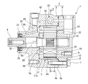
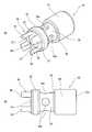
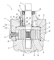
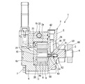
- FIG. 1 is a perspective view showing a variable displacement vane pump according to an embodiment of the present invention. It is a longitudinal cross-sectional view which shows the variable displacement vane pump.
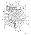
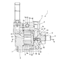
- FIG. 3 is a sectional view taken along line AA in FIG. 2. It is a longitudinal cross-sectional view which shows the principal part of the variable displacement vane pump.
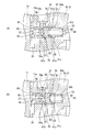
- 4A is an enlarged view of the main part of FIG. 4 showing a case where the differential pressure between the discharge pressure and the suction pressure acting on the first valve body is small
- FIG. 4B is an enlarged view of the main part of FIG. FIG. It is a perspective view showing the state where the 1st valve body concerning this embodiment was inserted in the front housing.
- variable displacement vane pump according to the present invention will be described in detail with reference to the drawings.
- this variable displacement vane pump is shown attached to a power steering device of an automobile.
- variable displacement vane pump 1 includes a pump housing 2 having a pump element accommodating chamber 2a that is a cylindrical pump element accommodating portion, and is accommodated in the pump element accommodating chamber 2a.
- the pump element 3 is provided, and the pump element 3 is rotationally driven by a drive shaft 4 inserted through the pump element accommodation chamber 2a to perform pump operation.
- the pump housing 2 includes a front housing 5 that is a first housing formed in a bottomed cylindrical shape, and a rear housing that is a second housing that closes an opening of the front housing 5. And a housing 6, both of which are fixed together by a plurality of bolts 7.
- the pump element 3 includes a substantially annular adapter ring 8 fitted and fixed to the inner peripheral surface of the cylindrical portion 5 a of the front housing 5, and a substantially oval shape of the adapter ring 8.
- a substantially annular cam ring 9 movably provided in an internal space formed in a shape; a rotor 10 provided integrally with the drive shaft 4 on the inner peripheral side of the cam ring 9; and the front housing 5 and a substantially disk-shaped pressure plate 11 that sandwiches the cam ring 9 and the rotor 10 together with the rear housing 6.
- the adapter ring 8 has a plate-like seal member 12 at the lower part of the inner peripheral surface 8a.
- the plate-like seal member 12 has a function of sealing between the adapter ring 8 and the cam ring 9 and serves as a rolling surface when the cam ring 9 moves in the internal space of the adapter ring 8. It has the function of
- the position opposite to the plate-like seal member 12 in the radial direction is the same as the plate-like seal member 12 between the adapter ring 8 and the cam ring 9.
- a seal member 13 is provided for sealing.
- the cam ring 9 defines a first fluid pressure chamber 14 and a second fluid pressure chamber 15 between the cam ring 9 and the adapter ring 8 through the seal members 12 and 13.
- the amount of eccentricity relative to the rotor 10 is increased or decreased by moving in the left-right direction in FIG.
- cam ring 9 is always urged in a direction in which the eccentric amount with respect to the rotor 10 is maximized by a return spring 16 that elastically contacts the outer periphery thereof.
- the position of the cam ring 9 is located between the adapter ring 8 and the cam ring 9 and on the counterclockwise direction in FIG. 3 of the plate-like seal member 12, that is, on the second fluid pressure chamber 15 side.
- a position holding pin 17 is provided to hold the.
- the position holding pin 17 has a function of preventing rotation of the cam ring 9 relative to the adapter ring 8 in addition to a function of holding the position of the cam ring 9.
- the rotor 10 rotates in the counterclockwise direction (arrow direction) in FIG.
- a plurality of slits 18 extending in the radial direction are formed in the outer peripheral portion of the rotor 10 at substantially equal intervals in the circumferential direction, and substantially flat vanes 19 are formed through the slits 18.
- the rotor 10 is accommodated so as to be able to appear and retract in the radial direction.
- Each vane 19 is always urged toward the inner peripheral surface of the cam ring 9 by the pressure of hydraulic oil that is hydraulic fluid introduced into a back pressure chamber 20 formed on the inner peripheral side of the rotor 10 of each slit 18. It has come to be.
- the seal ring groove 26 is formed in an annular shape on the outer peripheral side of the drive shaft 4 and accommodates therein a seal ring 27 that is a seal member for sealing between the front housing 5 and the drive shaft 4. Yes.
- a seal ring 27 that is a seal member for sealing between the front housing 5 and the drive shaft 4.
- FIGS. 1-10 a portion corresponding to a discharge region in which the volume of each pump chamber 21 is gradually reduced as the rotor 10 rotates, as shown in FIGS.
- An arc-shaped discharge port 28 is formed.
- the discharge port 28 communicates with a pressure chamber 29 that is recessed in the bottom wall portion 5 b of the front housing 5.
- the pressure chamber 29 has a role of urging the pressure plate 11 toward the rotor 10 by internal pressure.
- the discharge port 28 supplies hydraulic oil to a rotary valve of a power steering device (not shown) through a discharge passage 30 formed in the bottom wall portion 5b of the front housing 5. To supply.
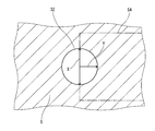
- the discharge passage 30 has a metering orifice 32 having a substantially circular cross section in the middle thereof, and the metering orifice 32 generates a differential pressure in the hydraulic oil.
- a flow rate control valve 33 is disposed at the upper end of the front housing 5.
- the flow control valve 33 is slidable inside the control valve accommodation hole 34 and a control valve accommodation hole 34 which is a second valve accommodation hole provided in the front housing 5 so as to be orthogonal to the drive shaft 4.
- a control valve body 35 that is a second valve body housed in the plug, a plug 36 that closes an opening on one axial end side of the control valve housing hole 34, and the control valve body 35 toward the plug 36 side.
- a valve spring 37 to be urged.
- control valve housing hole 34 is provided between the plug 36 and the control valve body 35 and introduces pressure (discharge pressure) upstream of the metering orifice 32.
- a damper orifice 42 is provided between the discharge passage 30 and the control pressure chamber 39 to reduce the influence of pulsation by lowering the fluid pressure of hydraulic oil introduced into the control pressure chamber 39. It has been.
- the control valve body 35 moves in the axial direction based on the differential pressure between the pressure in the high pressure chamber 38 and the pressure in the control pressure chamber 39.
- the suction pressure is introduced into the first fluid pressure chamber 14 from the low pressure chamber 41.
- the pressure difference between the high pressure chamber 38 and the control pressure chamber 39 is relatively large, and the control valve body 35 resists the pressure of the control pressure chamber 39 and the urging force of the valve spring 37 to the right in FIG.
- the communication between the low pressure chamber 41 and the first fluid pressure chamber 15 is gradually cut off, and the high pressure chamber 38 is communicated with the first fluid pressure chamber 14 via the communication passage 43.
- high pressure is introduced into the first fluid pressure chamber 14 from the high pressure chamber 38.
- the hydraulic pressure of the low pressure chamber 41 or the high pressure chamber 38 is selectively introduced into the first fluid pressure chamber 14.
- the pump suction pressure is always introduced into the second fluid pressure chamber 15, and when the suction pressure from the low pressure chamber 41 is introduced into the first fluid pressure chamber 14, Based on the urging force of the return spring 16, the cam ring 9 is disposed at a position where the eccentric amount with respect to the rotor 10 is maximized, and the pump discharge amount is maximized.
- the cam ring 9 decreases in the amount of eccentricity against the biasing force of the return spring 16 based on the high pressure, that is, Rolling to the second fluid pressure chamber 15 side reduces the pump discharge amount.
- a relief valve 44 is formed inside the control valve body 35.
- the relief valve 44 is opened when the pressure in the control pressure chamber 39 exceeds a predetermined value, that is, when the load pressure on the power steering device side exceeds a predetermined value.
- the low-pressure chamber 41 and the low-pressure passage 40 are circulated to the suction passage 23.
- the flow passage that reaches the downstream side of the metering orifice 32 in response to the load pressure on the power steering device side is located at a position immediately upstream of the metering orifice 32 in the discharge passage 30.
- a pressure sensitive valve 50 that changes the area is provided.
- the pressure sensitive valve 50 includes a bottomed columnar pressure sensitive valve accommodating hole 51 which is a first valve accommodating hole formed in the bottom wall portion 5b of the front housing 5;
- a cylindrical pressure-sensitive valve body 52 (spool valve) which is a first valve body slidably accommodated inside the pressure-sensitive valve accommodation hole 51, and urges the pressure-sensitive valve body 52 toward the pressure plate 11 side.
- a coil spring 53 that is a spring member.
- the pressure-sensitive valve housing hole 51 is formed in parallel with the drive shaft 4 and has a stepped diameter, and is formed at one end opening side in the axial direction.
- annular step surface 51c that is orthogonal to the axial direction is formed at the joint between the large-diameter hole 51a and the small-diameter hole 51b.
- the stepped surface 51c is configured to restrict the movement of the pressure-sensitive valve body 52 toward the small-diameter hole 51b when the amount of movement toward the small-diameter hole 51b is equal to or greater than a predetermined value. It functions as a stopper on the 51 side.
- the pressure-sensitive valve accommodating hole 51 is arranged in parallel with the drive shaft 4, the pressure-sensitive valve body 52 and the coil spring 53 are respectively along the axial direction of the drive shaft 4. It is supposed to move.
- the pressure sensitive valve accommodating hole 51 communicates with the metering orifice 32 at a substantially central position in the axial direction of the large diameter hole portion 51a.
- the pressure-sensitive valve housing hole 51 is formed so that the opening communicates with the discharge region indicated by a one-dot chain line in FIG. 6 and overlaps the discharge region in the circumferential direction of the drive shaft 4. Has been.
- the pressure-sensitive valve body 52 is a so-called spool valve formed in a cylindrical shape, and is provided at one end in the axial direction, and the inner circumference of the large-diameter hole 51a.
- a land portion 54 slidably formed on the surface and a guide portion provided on the other axial end side and slidably formed on the inner peripheral surface of the large-diameter hole portion 51 a in the same manner as the land portion 54.
- 55 and a passage constituting portion 56 that is provided integrally with an outer end portion in the axial direction of the guide portion 55 and forms a flow path for introducing hydraulic oil into the pressure receiving chamber 63 described later.
- the coil spring 53 is formed so that the spring constant has a substantially linear characteristic.
- the land portion 54 is formed on an annular flat surface whose one end surface 54a is a stopper, and comes into contact with a step surface 51c which is a stopper on the pressure-sensitive valve accommodating hole 51 side, thereby further increasing the above-mentioned feeling.
- the movement of the pressure valve body 52 toward one end side is restricted.
- the guide portion 55 slides on the inner peripheral surface of the pressure-sensitive valve housing hole 51 together with the land portion 54 to guide the movement of the pressure-sensitive valve body 52 so that the pressure-sensitive valve body 52 is not rattling. It comes to suppress.
- the passage constituting portion 56 is formed in a cylindrical shape slightly smaller in diameter than the guide portion 55, and includes four passage grooves 57 that are groove portions at substantially 90 ° intervals in the circumferential direction.
- Each passage groove 57 is notched in the radial direction of the pressure-sensitive valve body 52 so that the cross-sectional shape is a relatively large rectangular shape. That is, one end portion of the pressure-sensitive valve body 52 leaves four projecting portions 58 having a substantially triangular cross section, and most of the circumferential direction is cut away.
- annular groove 60 cut out in the circumferential direction is formed on the outer peripheral surface of the small-diameter portion 59 between the land portion 54 and the guide portion 55 of the pressure-sensitive valve body 52.
- the annular groove 60 has four communication holes 59a that communicate with the inside and the outside of the pressure-sensitive valve body 52 at approximately 90 ° intervals in the circumferential direction, and the pressure-sensitive valve body 52 is connected to each other through the communication holes 59a. It communicates with the inside of.
- a disk-shaped partition wall 61 is integrally formed at a portion of the pressure-sensitive valve body 52 inside the communication holes 59a on one end side.
- the partition wall 61 has an internal space of the pressure-sensitive valve accommodating hole 51, and a suction pressure chamber 62 on one end side that is cut off from the discharge passage 30 and each passage. It communicates with the discharge passage 30 through the groove 57 and is separated from the pressure receiving chamber 63 on the other end side where the discharge pressure is introduced.
- the suction pressure chamber 62 communicates with the seal ring groove 26 through a low pressure introduction passage 64 formed in the bottom surface of the pressure sensitive valve accommodating hole 51. Low pressure (suction pressure) is introduced.
- a spring holding groove 65 which is a cylindrical spring holding portion is formed at one end portion of the pressure sensitive valve body 52 constituting the suction pressure chamber 62.
- the spring holding groove 65 is composed of one end surface 61a of the partition wall 61 and an inner peripheral surface of the land portion 54.
- the spring holding groove 65 accommodates and holds a part of the coil spring 53 on the inner peripheral side, and at the groove bottom.
- One end face 61 a of the partition wall 61 is in elastic contact with one end portion of the coil spring 53.
- the other end of the coil spring 53 is elastically contacted with the bottom surface of the pressure-sensitive valve accommodating hole 51 (small diameter hole 51b). As a result, the coil spring 53 urges the pressure-sensitive valve body 52 toward the pressure plate 11 as described above.
- the pressure receiving chamber 63 is formed on the inner peripheral side of the pressure-sensitive valve body 52 and on the other end side of the partition wall 61, and is introduced from the passage constituting portion 56 as indicated by an arrow in FIG. After applying pressure to the other end surface 61 b of the partition wall 61, the pressure fluid is led out downstream of the metering orifice 32 through the communication holes 59 a and the annular groove 60.
- the pressure sensitive valve body 52 moves in the axial direction based on the differential pressure between the pressure in the pressure receiving chamber 63 and the pressure in the suction pressure chamber 62, and accordingly, the metering orifice 32 is moved by the outer peripheral surface of the land portion 54.
- the channel cross-sectional area is changed by closing a part of the channel.
- the pressure-sensitive valve body 52 is moved by the biasing force of the coil spring 53 as shown in FIG.
- the protrusions 58 and the pressure plate 11 are disposed at positions on the left side in the drawing. In this case, since the land portion 54 closes substantially half of the metering orifice 32, the cross-sectional area of the metering orifice 32 is almost halved.
- the pressure-sensitive valve body 52 is an opening portion of the pressure-sensitive valve housing hole 51 with respect to the pressure-sensitive valve housing hole 51 in which the coil spring 53 is incorporated when the variable displacement vane pump 1 is assembled. After being inserted from the side (the large-diameter hole 51a side) toward the bottom side, it is assembled by being closed by the pressure plate 11. [Effects of this embodiment] Therefore, according to this variable displacement vane pump 1, for example, during straight running that does not require steering assist force, most of the hydraulic oil supplied to the rotary valve (not shown) is used for steering assist. Therefore, the load pressure on the power steering device side is low.
- the metering orifice 32 is blocked by the pressure-sensitive valve body 52 (land portion 54).
- the amount is large and the cross-sectional area of the flow path is small. That is, the state is the same as when the amount of restriction in the variable orifice is increased.
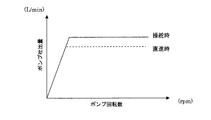
- the discharge amount of the hydraulic oil supplied to the power steering device is maintained in a relatively large amount as shown by the solid line in FIG. 9 during steering.
- variable displacement vane pump 1 various configurations such as the pump element 3, the suction passage 23, and the discharge passage 30 are provided inside the variable displacement vane pump 1 as in the present embodiment, making it difficult to provide a new configuration. ing.
- a region C as shown by a two-dot chain line in FIG. 4 is given as a portion where the configuration is not internally provided. Since the drive shaft 4 is inserted into the region C, It is necessary to avoid interference. For this reason, it is a substantial dead space for a mechanism or the like with complicated operation, and in providing a new configuration, the overall size of the apparatus accompanying the external attachment of the mechanism or the enlargement of the pump housing 2 or the like is increased. It was forced to become.
- the pressure sensitive valve 50 is provided so as to move along the axial direction of the drive shaft 4, interference with the drive shaft 4 can be avoided.
- the pressure sensitive valve accommodating hole 51 is arranged so as to overlap the discharge region in the circumferential direction of the drive shaft 4. Therefore, since the flow path for guiding the discharge pressure to the pressure sensitive valve accommodating hole 51 can be shortened, further space saving can be achieved.
- the pressure-sensitive valve body 52 is a spool valve and the flow passage cross-sectional area can be controlled only by changing the overlap amount between the land portion 54 and the metering orifice 32, the mechanism is complicated. Therefore, it is possible to suppress an increase in the size of the apparatus accompanying this.
- variable displacement vane pump 1 of the present embodiment an increase in the size of the device can be suppressed while reducing energy loss when applied to the power steering device.
- the other end side of the pressure sensitive valve accommodating hole 51 is provided so as to communicate with the discharge region via each passage groove 57, the discharge pressure can be easily introduced.
- the land portion 54 closes almost half of the metering orifice 32 and the land pressure increases from here.
- the closed area of the metering orifice 32 by the portion 54 is gradually reduced.
- the rate of change in the cross-sectional area of the flow path is large immediately after steering from straight ahead, and the flow rate increases rapidly with this, so that the steering response can be improved. Further, immediately after returning to straight running after turning, the rate of change of the channel cross-sectional area is small, and the flow rate gradually decreases.
- the pressure-sensitive valve body 52 is inserted from the opening side (the large-diameter hole 51a side) of the pressure-sensitive valve housing hole 51 and is closed by the pressure plate 11, the assembly is performed. Since a sealing member such as a sealing plug (plug) is not required, the cost can be reduced.
- the pressure sensitive valve accommodating hole 51 is provided close to the drive shaft 4, it is possible to easily connect the seal ring groove 26 communicating with the suction region. As a result, the suction pressure can be introduced also in the suction pressure chamber 62 disposed at a location separated from the suction region.
- each passage groove 57 notched in the radial direction is provided in the passage constituting portion 56 of the pressure-sensitive valve body 52, the passage constituting portion 56 is in contact with the pressure plate 11.
- hydraulic oil can be introduced into the pressure receiving chamber 63 from each passage groove 57.
- each passage groove 57 is formed so as to have a large opening area when introducing the hydraulic oil, the hydraulic oil can be taken in more efficiently.
- the one end surface 54a of the land portion 54 is formed as a flat surface, and this is brought into contact with the stepped surface 51c of the pressure-sensitive valve housing hole 51, whereby the pressure-sensitive valve body.
- the movement more than the predetermined to the one end side of 52 was controlled. Thereby, the problem that the said coil spring 53 is compressed too much and a linear characteristic changes can be avoided.
- the gap between the one end surface 54a of the land portion 54 and the stepped surface 51c of the pressure-sensitive valve accommodating hole 51 is sealed, the high-pressure side hydraulic oil is prevented from circulating to the low-pressure side, so that the pump Efficiency can be improved.
- the coil spring 53 can be prevented from falling by the spring holding groove 65 formed at one end of the pressure-sensitive valve body 52. Further, since the coil length of the coil spring 53 can be increased by the depth of the spring holding groove 65, a change in spring characteristics (linear characteristics) accompanying compression of the coil spring 53 can be further suppressed.
- the pressure fluid flowing through the discharge passage 30 is directly led to the downstream side of the metering orifice 32 while applying pressure to the pressure-sensitive valve body 52.
- the flow path formed in the pump housing 2 can be simplified compared to a configuration in which a pressure fluid is applied to the pressure-sensitive valve body 52 via a different flow path to control the position of the pressure-sensitive valve body 52.
- the apparatus can be simplified.
- [Second Embodiment] 11 to 13 show a second embodiment of the present invention.
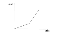
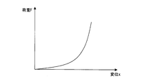
- the basic configuration is the same as that of the first embodiment, but a spring having a non-linear spring constant (non-linear spring) is applied as the coil spring 53.
- the coil spring 53 according to the present embodiment is formed such that at least one of the design parameters such as the coil diameter, the pitch, and the wire diameter changes along the axial direction of the coil spring 53.
- the relationship between the spring load F and the displacement x from the natural length (hereinafter simply referred to as “displacement x”) is non-linear.
- FIG. 11 and 12 show the relationship between the spring load F and the displacement x in an example of the coil spring 53 provided in the present embodiment.
- FIG. 11 shows the pitch between one end side and the other end side.
- FIG. 12 shows so-called tapered springs in which the coil diameter expands in a tapered shape from one end side to the other end side.
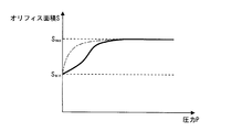
- orifice opening area S the change characteristic of the opening area S of the metering orifice 32 (hereinafter simply referred to as “orifice opening area S”) as the pressure P increases is affected by the cross-sectional shape (circular shape) of the metering orifice 32.
- the orifice opening area S changes from the minimum value S min to the maximum value S max, it changes most greatly at the beginning of the movement of the pressure-sensitive valve body 52, and gradually increases as the pressure P increases. It is uniquely determined so as to decrease (see the one-dot chain line in FIG. 13).
- the coil spring 53 since the coil spring 53 has non-linear characteristics, the amount of movement of the pressure P and the pressure-sensitive valve body 52 toward the small-diameter hole 51b has a proportional relationship. Instead, the pressure-sensitive valve body 52 moves greatly in a specific pressure range, or conversely, the amount of movement becomes small.
- the change characteristic of the orifice opening area S with the increase in the pressure P is greatly influenced not only by the cross-sectional shape (circular shape) of the metering orifice 32 but also by the spring characteristic of the coil spring 53. Will change.
- the change characteristic of the orifice opening area S accompanying the increase in the pressure P can be an irregular characteristic as shown by the solid line in FIG.
- This change characteristic can be freely adjusted to some extent by changing the coil spring 53 to one having a different non-linear characteristic.
- FIG. 14 shows a third embodiment of the present invention.
- the basic configuration is the same as that of the first embodiment, but the configuration of the pump housing 2 is changed.
- the same components as those in the first embodiment are denoted by the same reference numerals, and detailed description thereof is omitted.
- the pump housing 2 of the present embodiment includes a front housing 5 that is a first housing formed in a flat plate shape and a rear housing 6 that is a second housing formed in a bottomed cylindrical shape. And is composed of. And the opening part of the said rear housing 6 is obstruct
- the adapter ring 8 constituting the pump element 3 is adapted to be fitted and fixed to the inner peripheral surface of the cylindrical portion 6b of the rear housing 6, and
- the pressure plate 11 is arranged on the bottom wall portion 6 c of the rear housing 6 so as to sandwich the cam ring 9 and the rotor 10 together with the front housing 5.
- the drive shaft 4 that is pivotally supported by the pump housing 2 has one end portion 4a on the front housing 5 side projecting to the outside of the pump housing 2, and a pulley 66 serving as a drive shaft transmission portion on the projecting portion. Is provided.
- the pulley 66 rotates the drive shaft 4 by transmitting the engine power transmitted via a belt (not shown) to the drive shaft 4.
- the flow control valve 33 according to the present embodiment is changed to the upper end portion of the cylindrical portion 6b of the rear housing 6 in accordance with the configuration change of the pump housing 2.
- the location of the pressure sensitive valve 50 according to the present embodiment is also changed in accordance with the configuration change of the pump housing 2. That is, the pressure sensitive valve 50 according to the present embodiment has the pressure sensitive valve accommodating hole 51 in the middle of the discharge passage 30 and more than the rotor 10 in the axial direction of the drive shaft 4 of the front housing 5. It is arranged at a position on the pulley 66 side.
- the basic configuration is the same as that of the first embodiment, so that the pressure sensitive valve 50 increases the pump discharge amount or the steering assist force during steering when a large steering assist force is required. It is possible to reduce the pump discharge amount during straight traveling that does not require the. Thereby, since the pump discharge amount is optimized according to the operation state, the energy loss related to the pump operation can be reduced.
- the cross-sectional shape of the metering orifice 32 has been described as a circular shape.
- the pressure-sensitive valve body 52 due to the increase in the pressure of the hydraulic fluid flowing through the discharge passage 30, As long as the rate of change of the thickness gradually decreases, it may be formed in a cross-sectional shape.
- the pressure sensitive valve 50 has been described as changing the flow passage sectional area of the metering orifice 32 formed on the discharge passage 30, the metering orifice 32 is abolished and the discharge passage 30. You may comprise so that a flow-path cross-sectional area may be changed directly.
- the pressure fluid flowing through the discharge passage 30 is directly led to the downstream side of the metering orifice 32 while applying pressure to the pressure sensitive valve body 52.
- the pressure sensitive valve 50 is used as a pilot valve, a pilot flow path branched from the discharge passage 30 is further provided, and the pressure sensitive valve body 52 is moved by the pilot pressure of the pressure fluid flowing into the pilot flow path, thereby The flowing pressure fluid may be indirectly led to the downstream side of the metering orifice 32.
- the stopper for restricting the movement of the pressure-sensitive valve body 52 toward the one end side is the pressure-sensitive valve body 52 side (one end face 54a) and the pressure-sensitive valve housing hole 51 side (step surface 51c).
- the stopper may be provided in at least one of the pressure-sensitive valve body 52 and the pressure-sensitive valve accommodating hole 51.
- cam ring 9 has been described as increasing or decreasing the amount of eccentricity with respect to the rotor 10 by rolling the upper end surface of the plate-like seal member 12, the cam ring 9 is movably provided in the pump element accommodation chamber 2a.
- the method is not limited to this, and, for example, the position holding pin 17 may be used as a rocking fulcrum, and the amount of eccentricity may be changed by rocking.
Landscapes
- Engineering & Computer Science (AREA)
- Mechanical Engineering (AREA)
- General Engineering & Computer Science (AREA)
- Physics & Mathematics (AREA)
- Fluid Mechanics (AREA)
- Details And Applications Of Rotary Liquid Pumps (AREA)
- Rotary Pumps (AREA)
Abstract
Description
を備えたことを特徴としている。
〔本実施形態の作用効果〕
したがって、この可変容量形ベーンポンプ1によれば、例えば、操舵アシスト力を必要としない直進走行時にあっては、前記図外のロータリーバルブに供給された作動油は、その殆どが操舵アシストに供されることなく前記リザーバタンクTへ環流されることから、パワーステアリング装置側の負荷圧は低い状態となる。そして、これに伴いパワーステアリング装置と連通している吐出通路30内の作動油の流体圧も低い状態が維持されることから、前記感圧弁体52(ランド部54)によるメータリングオリフィス32の閉塞量が大きく、流路断面積が小さなものとなる。すなわち、可変オリフィスでいうところの絞り量が多くなった場合と同様の状態になる。
〔第2実施形態〕
図11~図13は本発明の第2実施形態を示し、基本構成は第1実施形態と同様であるが、コイルスプリング53として非線形のばね定数を有するばね(非線形ばね)を適用したものである。
〔第2実施形態の作用効果〕
前記第1実施形態では、前記コイルスプリング53が線形特性を有していることから、前記感圧弁体52に作用する圧力流体の圧力Pと、該感圧弁体52の小径穴部51b側への移動量がほぼ比例する。このため、前記圧力Pの上昇に伴うメータリングオリフィス32の開口面積S(以下、単に「オリフィス開口面積S」と呼ぶ)の変化特性は、前記メータリングオリフィス32の断面形状(円形状)の影響を大きく受けることとなって、オリフィス開口面積Sが最小値Sminから最大値Smaxに変化するにあたり、前記感圧弁体52の動き始めに最も大きく変化する一方、前記圧力Pが大きくなるにつれて漸次減少するように一意的に定められる(図13の一点鎖線参照)。
〔第3実施形態〕
図14は本発明の第3実施形態を示し、基本構成は第1実施形態と同様であるが、ポンプハウジング2の構成を変更したものである。なお、以下の説明においては、第1実施形態と共通の構成箇所には同一の符号を付して具体的な説明を省略する。
〔第3実施形態の作用効果〕
したがって、この実施形態においても、基本構成が第1実施形態と同様であることから、前記圧力感応弁50によって大きな操舵アシスト力が必要となる操舵時においてポンプ吐出量を増大させたり、操舵アシスト力を必要としない直進走行時においてポンプ吐出量を減少させたりすることが可能となる。これにより、ポンプ吐出量が運転状態に応じて適正化されることから、ポンプ作動に係るエネルギロスを低減することができる。
Claims (20)
- 車両のパワーステアリング装置に作動液を供給する可変容量形ベーンポンプであって、
筒状部と、該筒状部の一端開口を閉塞するように設けられた底壁部と、を有する第1ハウジングと、前記筒状部の他端開口を閉塞するように設けられた第2ハウジングと、から構成され、該両者間の内部にポンプ要素収容部を有するポンプハウジングと、
該ポンプハウジング内に挿通されて、回転自在に軸支される駆動軸と、
前記ポンプ要素収容部内に収容され、円周方向に複数のスリットが形成されていると共に、前記駆動軸に回転駆動されるロータと、
前記スリットに出没自在に設けられたベーンと、
前記ポンプ要素収容部内に移動可能に設けられ、前記ロータ及び前記ベーンと共に複数のポンプ室を形成する環状のカムリングと、
前記ポンプハウジングに設けられ、前記複数のポンプ室のうち前記ロータの回転に伴い容積が徐々に増大する吸入領域に開口する吸入口と、
前記ポンプハウジングに設けられ、前記複数のポンプ室のうち前記ロータの回転に伴い容積が徐々に減少する吐出領域に開口する吐出口と、
前記ポンプハウジングに設けられ、リザーバタンクに貯留された作動液を前記吸入口に供給する吸入通路と、
前記ポンプハウジングに設けられ、前記吐出口から吐出された作動液を前記ポンプハウジングの外部に供給する吐出通路と、
前記カムリングの外周側にそれぞれ設けられ、該カムリングが前記ロータに対する偏心量の増大する方向へ移動する場合において、容積が減少する側に形成された第1流体圧室と、容積が増大する側に形成された第2流体圧室と、
前記第1ハウジングの前記底壁部でかつ、前記吐出通路の途中に設けられた第1バルブ収容穴と、
前記第1バルブ収容穴内に移動可能に設けられ、一端側に作用する吸入圧と、前記吐出通路から導入されて他端側に作用する吐出圧との差圧に基づき移動制御されると共に、移動に伴い前記吐出通路の流路断面積を変化させる第1弁体と、
前記ポンプハウジングに設けられた第2バルブ収容穴と、
前記第2バルブ収容穴の一端側に設けられ、前記吐出口と連通するように形成された高圧室と、他端側に設けられ、前記吐出通路の前記第1バルブ収容穴より下流側と連通するように形成された制御圧室と、
前記第2バルブ収容穴内に移動可能に設けられ、前記高圧室の圧力と前記制御圧室の圧力との差圧に基づき、前記第1流体圧室の圧力を制御する第2弁体と、
を備えたことを特徴とする可変容量形ベーンポンプ。 - 請求項1に記載の可変容量形ベーンポンプにおいて、
前記第1弁体は、前記駆動軸の軸方向に沿って移動するように設けられることを特徴とする可変容量形ベーンポンプ。 - 請求項1に記載の可変容量形ベーンポンプにおいて、
前記第1バルブ収容穴は、開口部側が前記吐出領域と連通するように設けられることを特徴とする可変容量形ベーンポンプ。 - 請求項3に記載の可変容量形ベーンポンプにおいて、
前記第1バルブ収容穴は、前記駆動軸の円周方向において、前記吐出領域とオーバーラップするように設けられることを特徴とする可変容量形ベーンポンプ。 - 請求項4に記載の可変容量形ベーンポンプにおいて、
前記第1弁体は、前記第1バルブ収容穴の開口部側から挿入されることを特徴とする可変容量形ベーンポンプ。 - 請求項4に記載の可変容量形ベーンポンプにおいて、
前記ポンプハウジングは、
前記駆動軸の外周側に環状に形成され、前記ポンプハウジングと前記駆動軸との間をシールするシール部材を収容するシール部材収容部と、
前記シール部材収容部と前記吸入領域とを連通する低圧連通路と、
前記第1バルブ収容穴の一端側と前記シール部材収容部とを連通する低圧導入路と、
を有することを特徴とする可変容量形ベーンポンプ。 - 請求項1に記載の可変容量形ベーンポンプにおいて、
前記第1弁体は、ランドを有し、該ランドと前記吐出通路とのオーバーラップ量を変化させることにより、前記吐出通路の流路断面積を変化させるスプールバルブであることを特徴とする可変容量形ベーンポンプ。 - 請求項7に記載の可変容量形ベーンポンプにおいて、
前記第1弁体の他端側には、径方向に向かって切欠形成された溝部が形成されていることを特徴とする可変容量形ベーンポンプ。 - 請求項7に記載の可変容量形ベーンポンプは、
前記第1弁体を他端側に付勢するばね部材を有し、
前記第1弁体は、一端部に一端側方向への移動を規制するストッパを有することを特徴とする可変容量形ベーンポンプ。 - 請求項9に記載の可変容量形ベーンポンプにおいて、
前記ばね部材はコイルスプリングであって、
前記第1弁体は、一端側に前記ばね部材の一部を収容保持するスプリング保持部を有することを特徴とする可変容量形ベーンポンプ。 - 請求項9に記載の可変容量形ベーンポンプにおいて、
前記第1弁体は、前記ストッパにより移動が規制された際に、前記流路断面積が最大となるように形成されることを特徴とする可変容量形ベーンポンプ。 - 請求項7に記載の可変容量形ベーンポンプにおいて、
前記吐出通路は、前記第1弁体の他端側に作用する吐出圧の圧力上昇に伴って、前記流路断面積の変化率が漸次減少するように形成されることを特徴とする可変容量形ベーンポンプ。 - 請求項1に記載の可変容量形ベーンポンプは、
前記第1バルブ収容穴内に設けられ、前記第1弁体を付勢するばね部材を備え、
前記ばね部材は、非線形のばね定数を有することを特徴とする可変容量形ベーンポンプ。 - 請求項1に記載の可変容量形ベーンポンプにおいて、
前記第1弁体は、他端側に作用させた作動液を直接的に下流側へ導出することを特徴とする可変容量形ベーンポンプ。 - 請求項1に記載の可変容量形ベーンポンプにおいて、
前記第1バルブ収容穴は、その底部側が前記吸入通路と連通するように設けられることを特徴とする可変容量形ベーンポンプ。 - 車両のパワーステアリング装置に作動液を供給する可変容量形ベーンポンプであって、
平板状に形成された第1ハウジングと、筒状部と該筒状部の一端開口を閉塞するように設けられた底壁部とを有し、前記第1ハウジングによって前記筒状部の他端開口が閉塞される第2ハウジングと、から構成され、該両者間の内部にポンプ要素収容部を有するポンプハウジングと、
該ポンプハウジング内に挿通されて、回転自在に軸支される駆動軸と、
前記駆動軸のうち前記ポンプハウジングの外部に突出した部分に設けられ、外部の動力を前記駆動軸に伝達する駆動軸伝達部と、
前記ポンプ要素収容部内に収容され、円周方向に複数のスリットが形成されていると共に、前記駆動軸に回転駆動されるロータと、
前記スリットに出没自在に設けられたベーンと、
前記ポンプ要素収容部内に移動可能に設けられ、前記ロータ及び前記ベーンと共に複数のポンプ室を形成する環状のカムリングと、
前記ポンプハウジングに設けられ、前記複数のポンプ室のうち前記ロータの回転に伴い容積が徐々に増大する吸入領域に開口する吸入口と、
前記ポンプハウジングに設けられ、前記複数のポンプ室のうち前記ロータの回転に伴い容積が徐々に減少する吐出領域に開口する吐出口と、
前記ポンプハウジングに設けられ、リザーバタンクに貯留された作動液を前記吸入口に供給する吸入通路と、
前記ポンプハウジングに設けられ、前記吐出口から吐出された作動液を前記ポンプハウジングの外部に供給する吐出通路と、
前記カムリングの外周側にそれぞれ設けられ、該カムリングが前記ロータに対する偏心量の増大する方向へ移動する場合において、容積が減少する側に形成された第1流体圧室と、容積が増大する側に形成された第2流体圧室と、
前記第1ハウジングのうち、前記駆動軸の軸方向の前記ロータよりも前記駆動軸伝達部側の位置でかつ、前記吐出通路の途中に設けられた第1バルブ収容穴と、
前記第1バルブ収容穴内に移動可能に設けられ、一端側に作用する吸入圧と、前記吐出通路から導入されて他端側に作用する吐出圧との差圧に基づき移動制御されると共に、移動に伴い前記吐出通路の流路断面積を変化させる第1弁体と、
前記ポンプハウジングに設けられた第2バルブ収容穴と、
前記第2バルブ収容穴の一端側に設けられ、前記吐出口と連通するように形成された高圧室と、他端側に設けられ、前記吐出通路の前記第1バルブ収容穴より下流側と連通するように形成された制御圧室と、
前記第2バルブ収容穴内に移動可能に設けられ、前記高圧室の圧力と前記制御圧室の圧力との差圧に基づき、前記第1流体圧室の圧力を制御する第2弁体と、
を備えたことを特徴とする可変容量形ベーンポンプ。 - 請求項16に記載の可変容量形ベーンポンプにおいて、
前記第1弁体は、前記駆動軸の軸方向に沿って移動するように設けられることを特徴とする可変容量形ベーンポンプ。 - 請求項16に記載の可変容量形ベーンポンプにおいて、
前記第1バルブ収容穴は、開口部側が前記吐出領域と連通するように設けられることを特徴とする可変容量形ベーンポンプ。 - 請求項18に記載の可変容量形ベーンポンプにおいて、
前記第1バルブ収容穴は、前記駆動軸の円周方向において、前記吐出領域とオーバーラップするように設けられることを特徴とする可変容量形ベーンポンプ。 - 車両のパワーステアリング装置に作動液を供給する可変容量形ベーンポンプであって、
筒状部と、該筒状部の一端開口を閉塞するように設けられた底壁部と、を有する第1ハウジングと、前記筒状部の他端開口を閉塞するように設けられた第2ハウジングと、から構成され、該両者間の内部にポンプ要素収容部を有するポンプハウジングと、
該ポンプハウジング内に挿通されて、回転自在に軸支される駆動軸と、
前記ポンプ要素収容部内に収容され、円周方向に複数のスリットが形成されていると共に、前記駆動軸に回転駆動されるロータと、
前記スリットに出没自在に設けられたベーンと、
前記ポンプ要素収容部内に移動可能に設けられ、前記ロータ及び前記ベーンと共に複数のポンプ室を形成する環状のカムリングと、
前記ポンプハウジングに設けられ、前記複数のポンプ室のうち前記ロータの回転に伴い容積が徐々に増大する吸入領域に開口する吸入口と、
前記ポンプハウジングに設けられ、前記複数のポンプ室のうち前記ロータの回転に伴い容積が徐々に減少する吐出領域に開口する吐出口と、
前記ポンプハウジングに設けられ、リザーバタンクに貯留された作動液を前記吸入口に供給する吸入通路と、
前記ポンプハウジングに設けられ、前記吐出口から吐出された作動液を前記ポンプハウジングの外部に供給する吐出通路と、
前記カムリングの外周側にそれぞれ設けられ、該カムリングが前記ロータに対する偏心量の増大する方向へ移動する場合において、容積が減少する側に形成された第1流体圧室と、容積が増大する側に形成された第2流体圧室と、
前記第1ハウジングの前記底壁部でかつ、前記吐出通路の途中に設けられた第1バルブ収容穴と、
前記第1バルブ収容穴内に移動可能に設けられ、一端側に作用する吸入圧と、前記吐出通路から導入されて他端側に作用する吐出圧との差圧に基づき移動制御されると共に、移動に伴い前記吐出通路の流路断面積を変化させつつ、他端側に作用した作動液を導出する第1弁体と、
前記ポンプハウジングに設けられた第2バルブ収容穴と、
前記第2バルブ収容穴の一端側に設けられ、前記吐出口と連通するように形成された高圧室と、他端側に設けられ、前記吐出通路の前記第1バルブ収容穴より下流側と連通するように形成された制御圧室と、
前記第2バルブ収容穴内に移動可能に設けられ、前記高圧室の圧力と前記制御圧室の圧力との差圧に基づき、前記第1流体圧室の圧力を制御する第2弁体と、
を備えたことを特徴とする可変容量形ベーンポンプ。
Priority Applications (4)
| Application Number | Priority Date | Filing Date | Title |
|---|---|---|---|
| US15/520,195 US20170314555A1 (en) | 2014-11-21 | 2015-10-15 | Variable capacity vane pump |
| DE112015005251.8T DE112015005251T5 (de) | 2014-11-21 | 2015-10-15 | Flügelzellenpumpe mit variabler kapazität |
| CN201580056627.1A CN107076142A (zh) | 2014-11-21 | 2015-10-15 | 可变容量式叶片泵 |
| JP2016560114A JP6251822B2 (ja) | 2014-11-21 | 2015-10-15 | 可変容量形ベーンポンプ |
Applications Claiming Priority (2)
| Application Number | Priority Date | Filing Date | Title |
|---|---|---|---|
| JP2014236059 | 2014-11-21 | ||
| JP2014-236059 | 2014-11-21 |
Publications (1)
| Publication Number | Publication Date |
|---|---|
| WO2016080113A1 true WO2016080113A1 (ja) | 2016-05-26 |
Family
ID=56013671
Family Applications (1)
| Application Number | Title | Priority Date | Filing Date |
|---|---|---|---|
| PCT/JP2015/079106 Ceased WO2016080113A1 (ja) | 2014-11-21 | 2015-10-15 | 可変容量形ベーンポンプ |
Country Status (5)
| Country | Link |
|---|---|
| US (1) | US20170314555A1 (ja) |
| JP (1) | JP6251822B2 (ja) |
| CN (1) | CN107076142A (ja) |
| DE (1) | DE112015005251T5 (ja) |
| WO (1) | WO2016080113A1 (ja) |
Cited By (1)
| Publication number | Priority date | Publication date | Assignee | Title |
|---|---|---|---|---|
| WO2024190591A1 (ja) * | 2023-03-10 | 2024-09-19 | 日立Astemo株式会社 | 可変容量形ベーンポンプ |
Families Citing this family (7)
| Publication number | Priority date | Publication date | Assignee | Title |
|---|---|---|---|---|
| DE102015111344B4 (de) * | 2015-07-14 | 2025-05-08 | Robert Bosch Gmbh | Pulsationsgedämpfte kugelmutterlenkung und lenksystem |
| CN108843562A (zh) * | 2018-06-25 | 2018-11-20 | 东台帕瓦环保节能科技有限公司 | 一种节能型防回流液压泵 |
| EP3724505B1 (en) | 2019-01-31 | 2024-07-03 | Stackpole International Engineered Products, Ltd. | Pump with panic valve integrated in pivot pin |
| JP2022529922A (ja) | 2019-04-23 | 2022-06-27 | スタックポール インターナショナル エンジニアード プロダクツ,リミテッド. | 制御チャンバのための改良されたシールアセンブリを備えるベーンポンプ |
| GB2583542B (en) * | 2019-05-03 | 2021-10-13 | Leybold France S A S | Pump with exhaust valve |
| EP3973188A4 (en) | 2019-05-20 | 2023-06-07 | Stackpole International Engineered Products, Ltd. | SOLENOID VALVE FOR AN ADJUSTABLE VANE PUMP |
| DE102020122460A1 (de) * | 2020-08-27 | 2022-03-03 | Leistritz Pumpen Gmbh | Verfahren und Schraubenspindelpumpe zur Förderung eines Gas-Flüssigkeitsgemischs |
Citations (3)
| Publication number | Priority date | Publication date | Assignee | Title |
|---|---|---|---|---|
| JP2004293414A (ja) * | 2003-03-27 | 2004-10-21 | Kayaba Ind Co Ltd | 可変容量型ベーンポンプ及び圧力供給装置 |
| JP2010190071A (ja) * | 2009-02-17 | 2010-09-02 | Hitachi Automotive Systems Ltd | 可変容量形ポンプ及びこれを用いたパワーステアリング装置 |
| JP2012145095A (ja) * | 2010-12-21 | 2012-08-02 | Aisin Seiki Co Ltd | オイルポンプ |
Family Cites Families (7)
| Publication number | Priority date | Publication date | Assignee | Title |
|---|---|---|---|---|
| DE19846815B4 (de) * | 1997-10-16 | 2014-08-07 | Ixetic Bad Homburg Gmbh | Ventilanordnung und Pumpe für ein Getriebe |
| US6736604B2 (en) * | 2001-06-18 | 2004-05-18 | Unisia Jkc Steering Systems Co., Ltd. | Control apparatus of variable displacement pump for power steering apparatus |
| JP4009455B2 (ja) * | 2001-12-11 | 2007-11-14 | カヤバ工業株式会社 | 可変容量型ベーンポンプ |
| CN1309958C (zh) * | 2002-06-13 | 2007-04-11 | 尤尼西亚Jkc控制系统株式会社 | 可变排量泵 |
| JP4989392B2 (ja) * | 2007-09-21 | 2012-08-01 | 日立オートモティブシステムズ株式会社 | 可変容量形ポンプ |
| JP5065919B2 (ja) * | 2008-01-15 | 2012-11-07 | 日立オートモティブシステムズ株式会社 | ポンプ装置 |
| JP6177610B2 (ja) * | 2013-07-17 | 2017-08-09 | 日立オートモティブシステムズ株式会社 | 可変容量形ポンプ |
-
2015
- 2015-10-15 CN CN201580056627.1A patent/CN107076142A/zh active Pending
- 2015-10-15 JP JP2016560114A patent/JP6251822B2/ja not_active Expired - Fee Related
- 2015-10-15 US US15/520,195 patent/US20170314555A1/en not_active Abandoned
- 2015-10-15 WO PCT/JP2015/079106 patent/WO2016080113A1/ja not_active Ceased
- 2015-10-15 DE DE112015005251.8T patent/DE112015005251T5/de not_active Withdrawn
Patent Citations (3)
| Publication number | Priority date | Publication date | Assignee | Title |
|---|---|---|---|---|
| JP2004293414A (ja) * | 2003-03-27 | 2004-10-21 | Kayaba Ind Co Ltd | 可変容量型ベーンポンプ及び圧力供給装置 |
| JP2010190071A (ja) * | 2009-02-17 | 2010-09-02 | Hitachi Automotive Systems Ltd | 可変容量形ポンプ及びこれを用いたパワーステアリング装置 |
| JP2012145095A (ja) * | 2010-12-21 | 2012-08-02 | Aisin Seiki Co Ltd | オイルポンプ |
Cited By (1)
| Publication number | Priority date | Publication date | Assignee | Title |
|---|---|---|---|---|
| WO2024190591A1 (ja) * | 2023-03-10 | 2024-09-19 | 日立Astemo株式会社 | 可変容量形ベーンポンプ |
Also Published As
| Publication number | Publication date |
|---|---|
| DE112015005251T5 (de) | 2017-08-10 |
| CN107076142A (zh) | 2017-08-18 |
| JP6251822B2 (ja) | 2017-12-20 |
| JPWO2016080113A1 (ja) | 2017-05-25 |
| US20170314555A1 (en) | 2017-11-02 |
Similar Documents
| Publication | Publication Date | Title |
|---|---|---|
| JP6251822B2 (ja) | 可変容量形ベーンポンプ | |
| JP5216397B2 (ja) | 可変容量型ベーンポンプ | |
| JP5116546B2 (ja) | 可変容量型ベーンポンプ | |
| JP2005042675A (ja) | 可変容量形ポンプ | |
| WO2016125639A1 (ja) | 可変容量形ポンプ | |
| JP6700418B2 (ja) | 可変容量形ポンプ | |
| JP4319667B2 (ja) | 可変容量形ポンプ | |
| JP5371795B2 (ja) | 可変容量型ベーンポンプ | |
| JP3636880B2 (ja) | リリーフバルブ付きポンプ | |
| JP3481642B2 (ja) | 可変容量形ポンプ | |
| JP5583492B2 (ja) | 可変容量型ベーンポンプ | |
| JP2016118112A (ja) | ポンプ装置 | |
| US6267566B1 (en) | Oil pump | |
| JP4499694B2 (ja) | 可変容量形ポンプ | |
| WO2024190591A1 (ja) | 可変容量形ベーンポンプ | |
| US20200109709A1 (en) | Variable displacement oil pump | |
| JP5261235B2 (ja) | 可変容量ベーンポンプ | |
| JP2016211523A (ja) | ポンプ装置 | |
| JP3746388B2 (ja) | 可変容量型ベーンポンプ | |
| JP2000170668A (ja) | 可変容量形ポンプ | |
| KR20140036964A (ko) | 가변 용량형 베인 펌프 | |
| JP5555071B2 (ja) | ベーンポンプ | |
| JP5591143B2 (ja) | 可変容量型ベーンポンプ | |
| JP2009013958A (ja) | 可変容量型ベーンポンプ | |
| JP2010255551A (ja) | 可変容量型ベーンポンプ |
Legal Events
| Date | Code | Title | Description |
|---|---|---|---|
| 121 | Ep: the epo has been informed by wipo that ep was designated in this application |
Ref document number: 15861497 Country of ref document: EP Kind code of ref document: A1 |
|
| ENP | Entry into the national phase |
Ref document number: 2016560114 Country of ref document: JP Kind code of ref document: A |
|
| WWE | Wipo information: entry into national phase |
Ref document number: 15520195 Country of ref document: US |
|
| WWE | Wipo information: entry into national phase |
Ref document number: 112015005251 Country of ref document: DE |
|
| 122 | Ep: pct application non-entry in european phase |
Ref document number: 15861497 Country of ref document: EP Kind code of ref document: A1 |