WO2016079961A1 - 圧力センサの故障検出装置 - Google Patents
圧力センサの故障検出装置 Download PDFInfo
- Publication number
- WO2016079961A1 WO2016079961A1 PCT/JP2015/005650 JP2015005650W WO2016079961A1 WO 2016079961 A1 WO2016079961 A1 WO 2016079961A1 JP 2015005650 W JP2015005650 W JP 2015005650W WO 2016079961 A1 WO2016079961 A1 WO 2016079961A1
- Authority
- WO
- WIPO (PCT)
- Prior art keywords
- detection
- pressure sensor
- unit
- door
- rav
- Prior art date
- Legal status (The legal status is an assumption and is not a legal conclusion. Google has not performed a legal analysis and makes no representation as to the accuracy of the status listed.)
- Ceased
Links
Images




Classifications
-
- E—FIXED CONSTRUCTIONS
- E05—LOCKS; KEYS; WINDOW OR DOOR FITTINGS; SAFES
- E05B—LOCKS; ACCESSORIES THEREFOR; HANDCUFFS
- E05B81/00—Power-actuated vehicle locks
- E05B81/54—Electrical circuits
- E05B81/64—Monitoring or sensing, e.g. by using switches or sensors
- E05B81/66—Monitoring or sensing, e.g. by using switches or sensors the bolt position, i.e. the latching status
-
- E—FIXED CONSTRUCTIONS
- E05—LOCKS; KEYS; WINDOW OR DOOR FITTINGS; SAFES
- E05B—LOCKS; ACCESSORIES THEREFOR; HANDCUFFS
- E05B81/00—Power-actuated vehicle locks
- E05B81/54—Electrical circuits
- E05B81/64—Monitoring or sensing, e.g. by using switches or sensors
- E05B81/70—Monitoring or sensing, e.g. by using switches or sensors the wing position
-
- B—PERFORMING OPERATIONS; TRANSPORTING
- B60—VEHICLES IN GENERAL
- B60R—VEHICLES, VEHICLE FITTINGS, OR VEHICLE PARTS, NOT OTHERWISE PROVIDED FOR
- B60R21/00—Arrangements or fittings on vehicles for protecting or preventing injuries to occupants or pedestrians in case of accidents or other traffic risks
-
- B—PERFORMING OPERATIONS; TRANSPORTING
- B60—VEHICLES IN GENERAL
- B60R—VEHICLES, VEHICLE FITTINGS, OR VEHICLE PARTS, NOT OTHERWISE PROVIDED FOR
- B60R25/00—Fittings or systems for preventing or indicating unauthorised use or theft of vehicles
- B60R25/10—Fittings or systems for preventing or indicating unauthorised use or theft of vehicles actuating a signalling device
- B60R25/1004—Alarm systems characterised by the type of sensor, e.g. current sensing means
-
- E—FIXED CONSTRUCTIONS
- E05—LOCKS; KEYS; WINDOW OR DOOR FITTINGS; SAFES
- E05B—LOCKS; ACCESSORIES THEREFOR; HANDCUFFS
- E05B83/00—Vehicle locks specially adapted for particular types of wing or vehicle
- E05B83/36—Locks for passenger or like doors
-
- G—PHYSICS
- G01—MEASURING; TESTING
- G01L—MEASURING FORCE, STRESS, TORQUE, WORK, MECHANICAL POWER, MECHANICAL EFFICIENCY, OR FLUID PRESSURE
- G01L27/00—Testing or calibrating of apparatus for measuring fluid pressure
- G01L27/007—Malfunction diagnosis, i.e. diagnosing a sensor defect
-
- G—PHYSICS
- G07—CHECKING-DEVICES
- G07C—TIME OR ATTENDANCE REGISTERS; REGISTERING OR INDICATING THE WORKING OF MACHINES; GENERATING RANDOM NUMBERS; VOTING OR LOTTERY APPARATUS; ARRANGEMENTS, SYSTEMS OR APPARATUS FOR CHECKING NOT PROVIDED FOR ELSEWHERE
- G07C5/00—Registering or indicating the working of vehicles
- G07C5/08—Registering or indicating performance data other than driving, working, idle, or waiting time, with or without registering driving, working, idle or waiting time
- G07C5/0816—Indicating performance data, e.g. occurrence of a malfunction
Definitions
- the present disclosure relates to a pressure sensor failure detection device that detects a failure of a pressure sensor provided in a door of a vehicle.
- a pressure sensor is installed in the door of the vehicle to detect a pressure change in the door. That is.
- the volume in the door changes, and the pressure change is detected by the attached pressure sensor.
- an occupant protection device such as an air bag device or a seat belt pretensioner is activated to protect the occupant.
- the detection result by the pressure sensor mentioned above serves as a trigger which operates a passenger protection device, it must be what detected the pressure change in a door correctly. Therefore, when a failure occurs in the pressure sensor, it is necessary to accurately detect the failure and prevent malfunction of the occupant protection device.
- the pressure sensor provided in the door may detect a change in pressure due to an impact generated in the door.
- the abnormal value of the pressure sensor generated by the door closing operation is erroneously determined as a failure of the pressure sensor. If the pressure sensor is erroneously determined to be out of order, the operation of the occupant protection device is prohibited and the occupant cannot be protected from a vehicle collision.
- the present disclosure has been made in view of the above circumstances, and an object thereof is to provide a pressure sensor failure detection device capable of accurately determining whether or not a pressure sensor provided in a vehicle door is defective. There is.
- a failure detection device for a pressure sensor in a right door of a vehicle and detects a pressure change in the right door, and the vehicle.
- the left and right detection difference is calculated by calculating the difference between the left door pressure sensor that detects the pressure change in the left door, the detection value by the right door pressure sensor, and the detection value by the left door pressure sensor.
- a sensor failure detection unit that determines that the right door pressure sensor or the left door pressure sensor is defective when the left-right detection difference calculated by the detection value comparison unit is equal to or greater than a predetermined threshold value.
- the sensor failure detection unit reserves that the right door pressure sensor or the left door pressure sensor is determined to be defective, and the right door The detection value comparison unit again calculates the left-right detection difference after a lapse of a predetermined calming time that reduces the effect on the right door pressure sensor due to the closing operation of the left door or the effect on the left door pressure sensor due to the closing operation of the left door. After that, the result of comparing the left / right detection difference calculated again by the sensor failure detection unit with the threshold value indicates that the right door pressure sensor or the left door pressure sensor is determined to be defective when the difference is equal to or greater than the threshold value. I have.
- the pressure sensor failure detection device detects whether the right door pressure sensor or the left door is detected by the sensor failure detection unit when the left-right detection difference calculated by the detection value comparison unit is equal to or greater than the threshold value. It is reserved that the pressure sensor is determined to be faulty, and after the elapse of a predetermined calming time after which the influence on the right door pressure sensor due to the closing operation of the right door or the influence on the left door pressure sensor due to the closing operation of the left door is reduced. An external influence avoiding unit that determines that the right door pressure sensor or the left door pressure sensor has failed when the difference between the left and right detection differences calculated again is equal to or greater than the threshold is obtained.
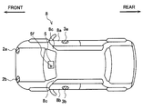
- FIG. 1 is a plan view of a vehicle to which the vehicle occupant protection device shown in FIG. 1 is attached.
- the vehicle occupant protection device 1 includes a right front acceleration sensor 2a and a left front acceleration sensor 2b, which are a pair of acceleration sensors.
- the right front acceleration sensor 2a and the left front acceleration sensor 2b are respectively provided on the left and right parts of the front surface of the vehicle 8, and detect the magnitude of impact applied in the front-rear direction of the vehicle 8 (shown in FIG. 2).
- the right front acceleration sensor 2a and the left front acceleration sensor 2b are collectively referred to as acceleration sensors 2a and 2b.
- the acceleration sensors 2a and 2b may be capacitive acceleration sensors, piezoresistive acceleration sensors, or heat detection type acceleration sensors.
- the right door pressure sensor 3a is attached in the driver's seat side door 8a (corresponding to the right door) of the vehicle 8 which is a right-hand drive vehicle.
- a left door pressure sensor 3b is attached in the passenger seat side door 8b of the vehicle 8 (corresponding to the left door).
- the right door pressure sensor 3a and the left door pressure sensor 3b detect pressure changes in the driver side door 8a and the passenger side door 8b, which are hinge doors, respectively, and detect the impact applied to the vehicle 8 in the left-right direction. is doing.
- the right door pressure sensor 3a and the left door pressure sensor 3b may be a semiconductor strain gauge pressure sensor, a capacitive pressure sensor, or other pressure sensors.
- the right door pressure sensor 3a and the left door pressure sensor 3b are collectively referred to as pressure sensors 3a and 3b.
- the vehicle occupant protection device 1 includes an ignition switch 4.
- the ignition switch 4 is provided in the vehicle 8 and is a device for operating an ignition device of an engine (not shown).
- the acceleration sensors 2a and 2b, the pressure sensors 3a and 3b, and the ignition switch 4 described above are connected to the airbag controller 5.
- the airbag controller 5 will be described later.
- An airbag device 6 (corresponding to an occupant protection unit) is connected to the airbag controller 5.
- the airbag device 6 is the same as that of the conventional type, and is formed by an inflator, a bag, and an ignition device (not shown).
- the airbag device 6 includes a driver airbag, a passenger airbag, a pillar airbag accommodated in the front pillar (A pillar) 8c, a curtain airbag accommodated in the right and left sides of the vehicle 8, and the like. Included (none of these airbags are shown).
- the airbag device 6 is deployed at the time of a collision of the vehicle 8 to protect the occupant's body against an impact applied to the vehicle 8.
- the airbag controller 5 is a control device formed by an input / output device, a CPU, a RAM, and the like, and is attached to the lower part of the dashboard in front of the driver's seat (shown in FIG. 2).
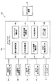
- the airbag controller 5 includes a detection value determination unit 5a, an airbag drive unit 5b, a left / right detection difference calculation unit 5c, a sensor failure detection unit 5d, a disturbance avoidance unit 5e, a floor acceleration sensor 5f, and an initial check unit 5g.
- the detection value determination unit 5a (corresponding to the collision detection unit) activates the airbag device 6 in the vehicle 8 based on the acceleration detected by the acceleration sensors 2a and 2b or the pressure change detected by the pressure sensors 3a and 3b.
- the airbag drive unit 5b (corresponding to the protection drive unit), when the detection value determination unit 5a determines that a collision that activates the airbag device 6 has occurred in the vehicle 8, causes the airbag device 6 to A squib current for activation is applied to the airbag device 6.
- the left / right detection difference calculation unit 5c (corresponding to the detection value comparison unit) calculates the difference between the detection value by the right door pressure sensor 3a and the detection value by the left door pressure sensor 3b, and the left / right detection difference
- the sensor failure detection unit 5d (corresponding to the sensor failure detection unit) detects the pressure sensor 3a when the left / right detection difference
- the failure is determined as 3b.
- the disturbance avoiding unit 5e (corresponding to the external influence avoiding unit) detects the sensor failure when the left / right detection difference
- the part 5d is reserved to determine that the pressure sensors 3a and 3b are out of order. Thereafter, a predetermined individual calming time Tdm (sedation) in which the influence on the right door pressure sensor 3a by the closing operation of the driver side door 8a or the influence on the left door pressure sensor 3b by the closing operation of the passenger side door 8b is reduced.
- the left / right detection difference calculator 5c is caused to calculate the left / right detection difference
- the sensor failure detection unit 5d compares the left-right detection difference
- the floor acceleration sensor 5f is formed so as to be able to detect the longitudinal and lateral accelerations of the vehicle 8.
- the floor acceleration sensor 5f may independently include a sensor that can detect the lateral direction of the vehicle 8 and a sensor that can detect the longitudinal acceleration of the vehicle 8.
- the initial check unit 5g (corresponding to the operation check unit) checks whether or not the airbag device 6 can be normally driven by the airbag controller 5 after the ignition switch 4 is turned on (initial check). is doing.
- the driver seat side door 8a or the passenger seat side door 8b which is a hinge door, is closed, the driver seat side door 8a and the passenger seat side door 8b are affected by the impact.
- the pressure sensors 3a and 3b incorporated on the side where the closing operation is performed detect a sudden increase in pressure (at the time indicated by t0 in FIG. 3). Thereafter, the pressure fluctuation is continuously detected by the pressure sensors 3a and 3b. Therefore, while the pressure fluctuation is continuing, failure determination of the pressure sensors 3a and 3b based on the above-described left / right detection difference
- the individual calming time Tdm elapses after the driver side door 8a or the passenger side door 8b is closed, the pressure fluctuation subsides and the failure determination of the pressure sensors 3a and 3b becomes possible.
- the specific value of the individual calming time Tdm described above can be obtained by repeated experiments using an actual vehicle.
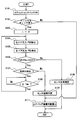
- step S101 when the ignition switch 4 of the vehicle 8 is turned on (step S101), it is determined by the initial check unit 5g whether the airbag device 6 can be normally driven (step S102). When it is determined by the initial check that there is an abnormality somewhere in the vehicle occupant protection device 1 and the airbag device 6 is not normally driven, the process proceeds to step S111. In step S111, the operation of the airbag device 6 by the airbag drive unit 5b is prohibited, and this flow ends.
- step S102 if it is determined in step S102 that there is no abnormality in the vehicle occupant protection device 1 and the airbag device 6 can be driven normally, the timer in the airbag controller 5 is reset after the count time is reset. Is started (step S103). Thereafter, the pressure PSR in the driver's seat side door 8a is detected by the right door pressure sensor 3a (step S104), and then the pressure PSL in the passenger seat side door 8b is detected by the left door pressure sensor 3b (step S104). Step S105). In this flow, the pressure PSL is detected by the left door pressure sensor 3b after the pressure PSR is detected by the right door pressure sensor 3a. However, since the time difference between the two is very small, There is no problem in that both are detected at the same point.
- the left / right detection difference calculation unit 5c calculates the first left / right detection difference
- step S106 when it is determined in step S106 that the left / right detection difference
- the disturbance avoiding unit 5e confirms that the individual calming time Tdm has passed by the timer, and then returns to step S104 again to execute the second pressure PSR and PSL detection (step S108). Thereafter, the left / right detection difference calculation unit 5c calculates the left / right detection difference
- step S107 the pressure PSR in the driver's seat side door 8a and the passenger seat side are again displayed. It is determined whether or not the detection of the pressure PSL in the door 8b is the first detection. If it is determined that the current detection of pressures PSR and PSL is not the first detection, it is determined that the pressure sensors 3a and 3b are out of order (step S110). Thereafter, in step S111, the operation of the airbag device 6 by the airbag driving unit 5b is prohibited, and this flow ends.
- the disturbance avoiding unit 5e of the vehicle occupant protection device 1 performs the case where the left / right detection difference
- the sensor failure detection unit 5d reserves that the pressure sensors 3a and 3b are determined to be failed. Thereafter, the disturbance avoiding unit 5e reduces the influence on the right door pressure sensor 3a due to the closing operation of the driver side door 8a or the influence on the left door pressure sensor 3b due to the closing operation of the passenger side door 8b. After the calming time Tdm has passed, the left-right detection difference
- the left / right detection difference calculation unit 5c calculates the first left / right detection difference
- the vehicle occupant protection device 1 includes a detection value determination unit 5a that detects that the vehicle 8 has collided based on detection values from the acceleration sensors 2a and 2b and the pressure sensors 3a and 3b, and an impact applied to the vehicle 8.
- the airbag device 6 that protects the occupant's body
- the airbag drive unit 5b that activates the airbag device 6 when the detected value determination unit 5a detects that the vehicle 8 has collided
- An initial check unit 5g for determining whether or not the bag device 6 is normally driven.
- the detection value determination unit 5a calculates the first left-right detection difference
- the abnormal state of the vehicle occupant protection device 1 can be eliminated before the failure detection of the pressure sensors 3a and 3b, the abnormal state caused by the failure of the pressure sensors 3a and 3b can be accurately detected. Can do.
- the airbag driving unit 5b prohibits the operation of the airbag device 6 when the sensor failure detection unit 5d determines that the pressure sensors 3a and 3b have failed. Thereby, malfunction of the airbag apparatus 6 resulting from failure of the pressure sensors 3a and 3b can be prevented, and the vehicle occupant protection apparatus 1 can be made safe and highly reliable. (Embodiment 2) Hereinafter, based on FIG. 5 thru
- the airbag controller 5A includes an average value calculation unit 5h (corresponding to an average value calculation unit) in addition to the configuration of the airbag controller 5 according to the first embodiment. It has.
- the average value calculator 5h calculates the right detection average value Rav by averaging the detection values by the right door pressure sensor 3a at two points (corresponding to a plurality of points) having different detection time points. Further, the left detection average value Lav is calculated by averaging the detection values by the left door pressure sensor 3b at the two points.
- the left / right detection difference calculation unit 5c calculates the difference between the right detection average value Rav and the left detection average value Rav calculated by the average value calculation unit 5h, and the left / right detection difference
- the right door pressure sensor 3a is configured such that the pressure Data in the driver's seat side door 8a is passed every time Tde ((Tde ⁇ 2) corresponds to a predetermined period). (NR) is detected. Further, the left door pressure sensor 3b detects the pressure Data (nL) in the passenger seat side door 8b every time the time Tde elapses (corresponds to a predetermined period of time).
- n represents the number of times of detection.
- the pressures Data (nR) and Data (nL) are detected at the same point.
- the above-described average value calculation unit 5h first averages the detection values Data1R and Data2R detected by the right door pressure sensor 3a for the pressure Data (nR) in the driver's seat side door 8a, and the right detection average value Rav at that time. Is calculated. Further, the average value calculation unit 5h averages the detection values Data1L and Data2L detected by the left door pressure sensor 3b for the pressure Data (nL) in the passenger seat side door 8b, and calculates the left detection average value Lav at that time. The left / right detection difference calculation unit 5c is based on the right detection average value Rav calculated by averaging the detection values Data1R and Data2R, and the left detection average value Lav calculated by averaging the detection values Data1L and Data2L.
- is calculated.
- the sensor failure detection unit 5d is a difference between the right detection average value Rav calculated by averaging the detection values Data1R and Data2R and the left detection average value Lav calculated by averaging the detection values Data1L and Data2L. Based on the left / right detection difference
- the disturbance avoidance unit 5e makes the sensor failure detection unit 5d reserve that it determines that the pressure sensors 3a and 3b are in failure when the left-right detection difference
- the average value calculation unit 5h averages the detection values Data3R and Data4R, calculates the right detection average value Rav at that time, averages the detection values Data3L and Data4L, and calculates the left detection average value Lav at that time Let it be calculated.
- is calculated, and the sensor failure detection unit 5d is caused to perform the second failure determination of the pressure sensors 3a and 3b.
- the disturbance avoiding unit 5e corresponds to the mutual calming time ⁇ (Tdm ⁇ 2) + (Tde ⁇ 2) ⁇ (settled time unless the pressure sensors 3a and 3b are determined to be normal on the way.
- is repeatedly calculated every time (Tde ⁇ 2) shorter than the calming time until the left and right detection difference calculation unit 5c passes.
- the disturbance avoidance unit 5e causes the sensor failure detection unit 5d to compare the left / right detection difference
- the disturbance avoiding unit 5e determines that the left / right detection difference
- the sensor failure detection unit 5d determines that the pressure sensors 3a and 3b are normal.
- the disturbance avoiding unit 5e avoids the influence on the right door pressure sensor 3a due to the closing operation of the driver's seat side door 8a or the influence on the left door pressure sensor 3b due to the closing operation of the passenger seat side door 8b.
- the strictest state is assumed. That is, in the present embodiment, a case is considered in which there is a closing operation of the passenger seat side door 8b and immediately after the influence on the left door pressure sensor 3b is reduced, there is a closing operation of the driver seat side door 8a.
- the order of the closing operation of the driver seat side door 8a and the passenger seat side door 8b may be interchanged).
- a state assumed to calculate the mutual calming time ⁇ (Tdm ⁇ 2) + (Tde ⁇ 2) ⁇ will be described in detail.
- the influence on the right door pressure sensor 3a due to the closing operation of the driver side door 8a or the left door pressure sensor 3b due to the closing operation of the passenger side door 8b is performed.
- the individual calming time Tdm described above is required.
- the closing operation of the passenger side door 8b is performed after the detection value Data1L is detected by the left door pressure sensor 3b and before the detection of Data2L.
- the effect on the left door pressure sensor 3b due to the closing operation of the passenger seat side door 8b extends from the detection value Data2L to Data (n ⁇ 1) L. Therefore, the failure determination of the pressure sensors 3a and 3b from the first time to the Nth time cannot be accurately performed by the sensor failure detection unit 5d.
- the driver's seat side door 8a is closed after the detection value Data (n + 1) R is detected by the right door pressure sensor 3a until the detection of Data (n + 2) R. To do.
- the mutual calming time during which the influence on the pressure sensors 3a and 3b due to the closing operation of the driver side door 8a or the closing operation of the passenger side door 8b is reduced is ⁇ (Tdm ⁇ 2) + ( Tde ⁇ 2) ⁇ (shown in FIG. 6).
- Ntr represents the number of times of failure determination of the pressure sensors 3a and 3b shown in FIG.
- Ntr represents the number of times of failure determination of the pressure sensors 3a and 3b shown in FIG.
- step S201 when the ignition switch 4 of the vehicle 8 is turned on (step S201), it is determined by the initial check unit 5g whether or not the airbag device 6 can be normally driven (step S202). If it is determined by the initial check that there is an abnormality somewhere in the vehicle occupant protection device 1A and the airbag device 6 is not driven normally, the process proceeds to step S211. In step S211, the operation of the airbag device 6 by the airbag drive unit 5b is prohibited, and this flow ends.
- the average value calculation unit 5h averages the detection values Data1R and Data2R, calculates the right detection average value Rav, averages the detection values Data1L and Data2L, and calculates the left detection average value Lav (step S207). Thereafter, using the detected right detection average value Rav and left detection average value Lav, the left / right detection difference calculation unit 5c calculates the left / right detection difference
- step S208 when it is determined in step S208 that the left / right detection difference
- the disturbance avoiding unit 5e returns to step S204 again, increments Ntr by 1, and then again detects the pressure Data (nR) and Data (nL).
- the left / right detection difference calculation unit 5c again performs the left / right detection difference
- the sensor failure detection unit 5d determines whether the left / right detection difference
- the vehicle occupant protection device 1A calculates the right detection average value Rav by averaging the detection values Data (nR) by the right door pressure sensor 3a at two points where the detection time points are different from each other.
- An average value calculation unit 5h is provided that averages the detection values Data (nL) detected by the left door pressure sensor 3b at two points to calculate the left detection average value Lav.
- the left / right detection difference calculation unit 5c calculates the difference between the right detection average value Rav and the left detection average value Lav calculated by the average value calculation unit 5h to calculate the left / right detection difference
- the pressure detection values Data (nR) and Data (nL) at the two detection points that are different from each other are averaged to calculate the right detection average value Rav and the left detection average value Lav. Can be reduced. Therefore, the accuracy of failure detection of the pressure sensors 3a and 3b can be improved.
- the disturbance avoidance unit 5e determines that when the left / right detection difference
- is repeatedly calculated, and the calculated right / left detection difference
- the disturbance avoidance unit 5e determines that the left / right detection difference
- the disturbance avoiding unit 5e reduces the influence on the right door pressure sensor 3a or the left door pressure sensor 3b by the closing operation of one of the driver seat side door 8a and the passenger seat side door 8b, and then reduces the driver seat. Assuming that the other of the side door 8a and the passenger side door 8b is closed, the mutual calming time ⁇ (Tdm ⁇ 2) + (Tde ⁇ 2) ⁇ is set.
- the present disclosure is not limited to the embodiment described above, and can be modified or expanded as follows.
- a seat belt device with a pretensioner when used as an occupant protection unit and the detection value by any of the acceleration sensors 2a, 2b and the pressure sensors 3a, 3b is equal to or greater than a predetermined threshold value, the seat belt The passenger may be protected by applying tension.
- the part to which the pressure sensors 3a and 3b are attached may be not only the driver's seat side door 8a and the passenger seat side door 8b but also the rear seat door of the vehicle 8. Further, the pressure sensors 3 a and 3 b may be attached to a slide door of the vehicle 8.
- a gyro sensor may be used in addition to the acceleration sensors 2a and 2b and the pressure sensors 3a and 3b.
- the detection values Data (nR) and Data (nL) detected by the pressure sensors 3a and 3b at three or more different detection time points are averaged to obtain the right detection average value Rav and the left detection average value Lav. May be calculated.
- every time Tde elapses, left and right detection is performed using the detection values PSR and PSL detected by the pressure sensors 3a and 3b (without calculating the right detection average value Rav and the left detection average value Lav).
- a failure of the pressure sensors 3a and 3b may be detected by calculating the difference
Landscapes
- Engineering & Computer Science (AREA)
- Physics & Mathematics (AREA)
- General Physics & Mathematics (AREA)
- Mechanical Engineering (AREA)
- Health & Medical Sciences (AREA)
- Chemical & Material Sciences (AREA)
- Analytical Chemistry (AREA)
- Biomedical Technology (AREA)
- Air Bags (AREA)
- Measuring Fluid Pressure (AREA)
Abstract
圧力センサの故障検出装置(1)は、右・左ドア圧力センサ(3a、3b)と、左右検出差(|PSR-PSL|、|Rav-Lav|)を算出する検出値比較部(5c)と、左右検出差が所定の閾値(Dif)以上のとき、右または左ドア圧力センサの故障と判定するセンサ故障検出部(5d)とを備え、初回に算出された左右検出差が閾値以上のとき、センサ故障検出部により右または左ドア圧力センサを故障と判定することを留保させ、右側ドア(8a)の閉動作による右ドア圧力センサへの影響または左側ドア(8b)の閉動作による左ドア圧力センサへの影響が低減する沈静化時間(Tdm、{(Tdm×2)+(Tde×2)})経過後に、検出値比較部により再度左右検出差を演算させた後、センサ故障検出部により再度演算された左右検出差を閾値と比較させた結果、閾値以上のときに右または左ドア圧力センサの故障と判定させる外部影響回避部(5e)を備える。
Description
本出願は、2014年11月17日に出願された日本特許出願番号2014-232905号に基づくもので、ここにその記載内容を援用する。
本開示は、車両のドアに設けられた圧力センサの故障を検出する圧力センサの故障検出装置に関する。
主に、車両の側面への衝突(以下、側突という)を検出するために、車両のドア内に圧力センサを取り付け、ドア内の圧力変化を検出することは、これまで、行われていることである。車両に側突が発生すると、ドア内の容積が変化し、取り付けられた圧力センサによってその圧力変化が検出される。これにより、車両への側突が検出され、乗員を保護するために、エアバッグ装置またはシートベルトプリテンショナー等の乗員保護装置が作動される。ところで、上述した圧力センサによる検出結果は、乗員保護装置を作動させるトリガとなるため、ドア内の圧力変化を正確に検出したものでならなければならない。したがって、圧力センサに故障が生じた場合には、当該故障を的確に検知して、乗員保護装置の誤作動を防止する必要があった。
この課題に対して、車両の左右のドア内に設けられた一対の圧力センサの検出値を互いに比較し、双方の検出値が所定の程度を超えて異なっている場合に、いずれかの圧力センサの故障と判定する圧力センサの故障検出方法に関する従来技術があった(例えば、特許文献1参照)。双方の圧力センサが同時に故障することは非常に稀であることからすれば、当該従来技術によって、いずれかの圧力センサの故障を検出することが可能となる。また、車両が標高の高い地点にある場合においては、周囲の気圧の変化によって、双方の圧力センサが異常値を検出する。このため、上述した従来技術によれば、車両が位置する標高に起因した圧力センサの異常とは区別されて、いずれかの圧力センサの故障の有無を検出することができる。
ところで、車両のドアを強い力で閉めた場合、ドアに発生する衝撃によって、ドア内に設けられた圧力センサが圧力変化を検出する場合がある。ドアの閉動作によって発生する圧力センサの異常値は、圧力センサの故障と誤判定される場合が多かった。圧力センサが故障と誤判定されると、乗員保護装置の作動が禁止され、車両の衝突から乗員を保護することができなかった。
本開示は上記事情に鑑みてなされたものであり、その目的は、車両のドア内に設けられた圧力センサの故障の有無を正確に判定することが可能な圧力センサの故障検出装置を提供することにある。
上述した目的を解決するために、本開示の1つの態様に係る圧力センサの故障検出装置は、車両の右側ドア内に設けられ、右側ドア内の圧力変化を検出する右ドア圧力センサと、車両の左側ドア内に設けられ、左側ドア内の圧力変化を検出する左ドア圧力センサと、右ドア圧力センサによる検出値と、左ドア圧力センサによる検出値との差を演算して、左右検出差を算出する検出値比較部と、検出値比較部によって算出された左右検出差が、所定の閾値以上である場合に、右ドア圧力センサまたは左ドア圧力センサの故障と判定するセンサ故障検出部と、を備える。検出値比較部によって、初回に算出された左右検出差が閾値以上であった場合に、センサ故障検出部によって、右ドア圧力センサまたは左ドア圧力センサを故障と判定することを留保させ、右側ドアの閉動作による右ドア圧力センサへの影響または左側ドアの閉動作による左ドア圧力センサへの影響が低減する所定の沈静化時間経過後に、検出値比較部によって、再度、左右検出差を演算させた後、センサ故障検出部によって、再度演算された左右検出差を閾値と比較させた結果、閾値以上である場合に、右ドア圧力センサまたは左ドア圧力センサの故障と判定させる外部影響回避部を備えている。
この構成によれば、圧力センサの故障検出装置は、検出値比較部によって、初回に算出された左右検出差が閾値以上であった場合に、センサ故障検出部によって、右ドア圧力センサまたは左ドア圧力センサを故障と判定することを留保させ、右側ドアの閉動作による右ドア圧力センサへの影響または左側ドアの閉動作による左ドア圧力センサへの影響が低減する所定の沈静化時間経過後に、再度演算された左右検出差を閾値と比較させた結果、閾値以上である場合に、右ドア圧力センサまたは左ドア圧力センサの故障と判定させる外部影響回避部を備えている。このため、右側ドアまたは左側ドアの閉動作による右ドア圧力センサまたは左ドア圧力センサへの影響が低減してから演算された左右検出差に基づき、右ドア圧力センサまたは左ドア圧力センサの故障の有無を正確に判定することができる。
本開示についての上記目的およびその他の目的、特徴や利点は、添付の図面を参照しながら下記の詳細な記述により、より明確になる。その図面は、
実施形態1による車両用乗員保護装置の構成を示したブロック図
図1に示した車両用乗員保護装置が取り付けられた車両の平面図
実施形態1の車両のドア内に取り付けられた圧力センサによる圧力検出値の時間的変化を模式的に示した図
図1に示した車両用乗員保護装置による故障検出方法の制御フローチャートを示した図
実施形態2による車両用乗員保護装置の構成を示したブロック図
図5に示した車両用乗員保護装置による故障検出方法を説明するためのタイムチャートを示した図
図5に示した車両用乗員保護装置による故障検出方法の制御フローチャートを示した図
(実施形態1)
図1乃至図4に基づき、実施形態1による車両用乗員保護装置1(圧力センサの故障検出装置に該当する)について説明する。図1に示すように、本実施形態による車両用乗員保護装置1は、一対の加速度センサである右前方加速度センサ2aおよび左前方加速度センサ2bを備えている。右前方加速度センサ2aおよび左前方加速度センサ2bは、それぞれ車両8の前面の左右部位に設けられ、車両8の前後方向に加えられた衝撃の大きさを検出している(図2示)。以下、右前方加速度センサ2aおよび左前方加速度センサ2bを総称する場合、加速度センサ2a、2bと言う。加速度センサ2a、2bは、静電容量型加速度センサであっても、ピエゾ抵抗式加速度センサであっても、熱検知方式の加速度センサであってもよい。
図1乃至図4に基づき、実施形態1による車両用乗員保護装置1(圧力センサの故障検出装置に該当する)について説明する。図1に示すように、本実施形態による車両用乗員保護装置1は、一対の加速度センサである右前方加速度センサ2aおよび左前方加速度センサ2bを備えている。右前方加速度センサ2aおよび左前方加速度センサ2bは、それぞれ車両8の前面の左右部位に設けられ、車両8の前後方向に加えられた衝撃の大きさを検出している(図2示)。以下、右前方加速度センサ2aおよび左前方加速度センサ2bを総称する場合、加速度センサ2a、2bと言う。加速度センサ2a、2bは、静電容量型加速度センサであっても、ピエゾ抵抗式加速度センサであっても、熱検知方式の加速度センサであってもよい。
右ハンドル車である車両8の運転手席側ドア8a内(右側ドア内に該当する)には、右ドア圧力センサ3aが取り付けられている。また、車両8の助手席側ドア8b内(左側ドア内に該当する)には、左ドア圧力センサ3bが取り付けられている。右ドア圧力センサ3aおよび左ドア圧力センサ3bは、それぞれヒンジドアである運転手席側ドア8a内および助手席側ドア8b内の圧力変化を検出し、車両8の左右方向に加えられた衝撃を検知している。右ドア圧力センサ3aおよび左ドア圧力センサ3bは、半導体歪ゲージ式圧力センサまたは静電容量式圧力センサあるいはその他の圧力センサであってもよい。以下、右ドア圧力センサ3aおよび左ドア圧力センサ3bを総称する場合、圧力センサ3a、3bと言う。また、車両用乗員保護装置1は、イグニッションスイッチ4を備えている。イグニッションスイッチ4は車両8に設けられ、エンジン(図示せず)のイグニッション装置を作動させるための装置である。
上述した加速度センサ2a、2b、圧力センサ3a、3bおよびイグニッションスイッチ4は、エアバッグコントローラー5に接続されている。エアバッグコントローラー5については、後述する。エアバッグコントローラー5には、エアバッグ装置6(乗員保護部に該当する)が接続されている。エアバッグ装置6は従前のタイプのものと同様であって、図示しないインフレータ、バッグおよび点火装置により形成されている。エアバッグ装置6には、運転席エアバッグ、助手席エアバッグ、フロントピラー(Aピラー)8c内に収容されたピラーエアバッグ、車両8の右側部および左側部に収容されたカーテンエアバッグ等が含まれる(これらのエアバッグは、いずれも図示せず)。エアバッグ装置6は、車両8の衝突時において展開することにより、車両8に加えられた衝撃に抗して乗員の身体を保護している。
エアバッグコントローラー5は、入出力装置、CPU、RAM等により形成された制御装置であって、運転席前側のダッシュボード下方部に取り付けられている(図2示)。エアバッグコントローラー5は、検出値判定部5a、エアバッグ駆動部5b、左右検出差演算部5c、センサ故障検出部5d、外乱回避部5e、フロア加速度センサ5fおよびイニシャルチェック部5gを備えている。検出値判定部5a(衝突検出部に該当する)は、加速度センサ2a、2bによって検出された加速度または圧力センサ3a、3bによって検出された圧力変化に基づき、車両8において、エアバッグ装置6を作動させるような衝突が発生したか否かを判定する。エアバッグ駆動部5b(保護駆動部に該当する)は、検出値判定部5aによって、車両8において、エアバッグ装置6を作動させるような衝突が発生したと判定された場合、エアバッグ装置6を作動させるためのスクイブ電流を、エアバッグ装置6に対し印加する。左右検出差演算部5c(検出値比較部に該当する)は、右ドア圧力センサ3aによる検出値と、左ドア圧力センサ3bによる検出値との差を演算して、左右検出差|PSR-PSL|(≧0)を算出する。センサ故障検出部5d(センサ故障検出部に該当する)は、左右検出差演算部5cによって算出された左右検出差|PSR-PSL|が、所定の閾値Dif以上である場合に、圧力センサ3a、3bの故障と判定する。
外乱回避部5e(外部影響回避部に該当する)は、左右検出差演算部5cによって、初回において算出された左右検出差|PSR-PSL|が、閾値Dif以上であった場合に、センサ故障検出部5dに、圧力センサ3a、3bを故障と判定することを留保させる。その後、運転手席側ドア8aの閉動作による右ドア圧力センサ3aへの影響または助手席側ドア8bの閉動作による左ドア圧力センサ3bへの影響が低減する所定の個別沈静化時間Tdm(沈静化時間に該当する)経過後に、左右検出差演算部5cに、再度、左右検出差|PSR-PSL|を演算させる。次に、センサ故障検出部5dに、再度演算された左右検出差|PSR-PSL|を閾値Difと比較させた結果、閾値Dif以上である場合に、圧力センサ3a、3bの故障と判定させる。フロア加速度センサ5fは、車両8の前後方向および左右方向の加速度を検出することが可能に形成されている。尚、フロア加速度センサ5fは、車両8の左右方向を検出することができるセンサと、車両8の前後方向の加速度を検出することができるセンサとを独立に有していてもよい。イニシャルチェック部5g(作動チェック部に該当する)は、イグニッションスイッチ4がオンされた後、エアバッグコントローラー5によってエアバッグ装置6が正常に駆動されることが可能か否かをチェック(イニシャルチェック)している。
図3に示したように、車両8において、ヒンジドアである運転手席側ドア8aまたは助手席側ドア8bが閉じられると、その衝撃によって、運転手席側ドア8aおよび助手席側ドア8bのうち、その閉作動が行われた側に内蔵された圧力センサ3a、3bが、急激な圧力の上昇を検出する(図3において、t0にて示した時点)。その後、圧力センサ3a、3bによって、圧力変動が継続して検出される。したがって、当該圧力変動の継続中においては、前述した左右検出差|PSR-PSL|に基づいた、圧力センサ3a、3bの故障判定を正確に行うことはできない。しかしながら、運転手席側ドア8aまたは助手席側ドア8bが閉じられてから、前述の個別沈静化時間Tdmが経過すると、圧力変動は治まって、圧力センサ3a、3bの故障判定が可能となる。上述した個別沈静化時間Tdmの具体的な値については、実際の車両を用いた反復的な実験によって求めることが可能である。
次に、図4に基づき、本実施形態のエアバッグコントローラー5による圧力センサ3a、3bの故障検出方法のフローについて説明する。最初に、車両8のイグニッションスイッチ4がオンされると(ステップS101)、イニシャルチェック部5gによって、エアバッグ装置6が正常に駆動されることが可能か否か判定される(ステップS102)。イニシャルチェックによって、車両用乗員保護装置1のどこかに異常があり、エアバッグ装置6が正常に駆動されないと判定された場合、ステップS111へと進む。ステップS111においては、エアバッグ駆動部5bによるエアバッグ装置6の作動が禁止され、本フローは終了する。一方、ステップS102において、車両用乗員保護装置1に異常がなく、エアバッグ装置6が正常に駆動されることが可能と判定された場合、カウント時間をリセットした後、エアバッグコントローラー5内のタイマーが開始される(ステップS103)。その後、右ドア圧力センサ3aにより、運転手席側ドア8a内の圧力PSRを検出し(ステップS104)、次に、左ドア圧力センサ3bにより、助手席側ドア8b内の圧力PSLを検出する(ステップS105)。本フローにおいて、右ドア圧力センサ3aによる圧力PSRの検出の後に、左ドア圧力センサ3bによる圧力PSLの検出が行われるとされているが、双方の時間的な差はごく僅かであるため、実際には、双方は同時点において検出されているとすることに支障はない。
その後、検出された圧力PSR、PSLを用いて、左右検出差演算部5cが初回の左右検出差|PSR-PSL|を演算し、センサ故障検出部5dが、左右検出差演算部5cにより算出された左右検出差|PSR-PSL|が、閾値Dif以上であるか否かを判定する(ステップS106)。左右検出差|PSR-PSL|が、閾値Dif未満(閾値未満に該当する)である場合、圧力センサ3a、3bは正常と判定され、本フローは終了する(ステップS109)。一方、ステップS106において、左右検出差|PSR-PSL|が、閾値Dif以上であると判定された場合、外乱回避部5eによって、今回の運転手席側ドア8a内の圧力PSRおよび助手席側ドア8b内の圧力PSLの検出が、初回の検出であるか否か判定される(ステップS107)。外乱回避部5eは、今回の圧力PSR、PSLの検出が初回の検出である場合、センサ故障検出部5dに、圧力センサ3a、3bを故障と判定させることはない(故障と判定することを留保させる)。
その後、外乱回避部5eは、タイマーによって個別沈静化時間Tdmが経過したことを確認した後、再び、ステップS104へと戻り、2回目の圧力PSR、PSLの検出を実行させる(ステップS108)。その後、左右検出差演算部5cが、検出された圧力PSR、PSLを用いて、再度、左右検出差|PSR-PSL|を演算し、センサ故障検出部5dが、左右検出差演算部5cにより算出された左右検出差|PSR-PSL|が、閾値Dif以上であるか否かを判定する(ステップS106)。センサ故障検出部5dにより、左右検出差|PSR-PSL|が、閾値Dif以上であると判定された場合、ステップS107において、再び、今回の運転手席側ドア8a内の圧力PSRおよび助手席側ドア8b内の圧力PSLの検出が、初回の検出であるか否か判定される。今回の圧力PSR、PSLの検出が、初回の検出ではないと判定された場合、圧力センサ3a、3bの故障であると判定される(ステップS110)。その後、ステップS111において、エアバッグ駆動部5bによるエアバッグ装置6の作動が禁止され、本フローは終了する。
本実施形態によれば、車両用乗員保護装置1の外乱回避部5eは、左右検出差演算部5cによって、初回に算出された左右検出差|PSR-PSL|が閾値Dif以上であった場合に、センサ故障検出部5dによって、圧力センサ3a、3bを故障と判定することを留保させる。その後、外乱回避部5eは、運転手席側ドア8aの閉動作による右ドア圧力センサ3aへの影響または助手席側ドア8bの閉動作による左ドア圧力センサ3bへの影響が低減する所定の個別沈静化時間Tdm経過後に、再度演算された左右検出差|PSR-PSL|を閾値Difと比較させる。その結果、閾値Dif以上である場合に、圧力センサ3a、3bの故障と判定させる。このため、運転手席側ドア8aまたは助手席側ドア8bの閉動作による圧力センサ3a、3bへの影響が低減してから演算された左右検出差|PSR-PSL|に基づき、圧力センサ3a、3bの故障の有無を正確に判定することができる。また、左右検出差演算部5cは、車両8のイグニッションスイッチ4がオンされた時に、初回の左右検出差|PSR-PSL|を演算している。これにより、圧力センサ3a、3bの故障検出を常時行うことがなく、故障検出にともなうエアバッグコントローラー5および車両用乗員保護装置1全体の負担を低減することができる。
また、車両用乗員保護装置1は、加速度センサ2a、2bおよび圧力センサ3a、3bによる検出値に基づき、車両8が衝突したことを検出する検出値判定部5aと、車両8に加えられた衝撃に抗して、乗員の身体を保護するエアバッグ装置6と、検出値判定部5aによって車両8が衝突したことを検出した場合に、エアバッグ装置6を作動させるエアバッグ駆動部5bと、エアバッグ装置6が正常に駆動されるか否かを判定するイニシャルチェック部5gとを備えている。検出値判定部5aは、イニシャルチェック部5gによって、エアバッグ装置6が正常に駆動されると判定された後に、初回の左右検出差|PSR-PSL|を演算している。これにより、圧力センサ3a、3bの故障検出の前に、車両用乗員保護装置1の異常状態を排除することができるため、圧力センサ3a、3bの故障に起因した異常状態を正確に検出することができる。また、エアバッグ駆動部5bは、センサ故障検出部5dによって、圧力センサ3a、3bの故障と判定された場合、エアバッグ装置6の作動を禁止する。これにより、圧力センサ3a、3bの故障に起因したエアバッグ装置6の誤作動を防止することができ、安全で信頼性の高い車両用乗員保護装置1にすることができる。
(実施形態2)
以下、図5乃至図7に基づき、実施形態2による車両用乗員保護装置1A(圧力センサの故障検出装置に該当する)について、実施形態1に対する相違点のみについて説明する。図5に示したように、本実施形態によるエアバッグコントローラー5Aは、実施形態1によるエアバッグコントローラー5が有している構成に加えて、平均値演算部5h(平均値算出部に該当する)を備えている。平均値演算部5hは、検出時点が互いに異なる2点(複数の点に該当する)における右ドア圧力センサ3aによる検出値を平均化して、右検出平均値Ravを算出する。また、当該2点における左ドア圧力センサ3bによる検出値を平均化して、左検出平均値Lavを算出する。本実施形態による左右検出差演算部5cは、平均値演算部5hによって算出された右検出平均値Ravと左検出平均値Ravとの差を演算して、左右検出差|Rav-Lav|(≧0)を算出する。
(実施形態2)
以下、図5乃至図7に基づき、実施形態2による車両用乗員保護装置1A(圧力センサの故障検出装置に該当する)について、実施形態1に対する相違点のみについて説明する。図5に示したように、本実施形態によるエアバッグコントローラー5Aは、実施形態1によるエアバッグコントローラー5が有している構成に加えて、平均値演算部5h(平均値算出部に該当する)を備えている。平均値演算部5hは、検出時点が互いに異なる2点(複数の点に該当する)における右ドア圧力センサ3aによる検出値を平均化して、右検出平均値Ravを算出する。また、当該2点における左ドア圧力センサ3bによる検出値を平均化して、左検出平均値Lavを算出する。本実施形態による左右検出差演算部5cは、平均値演算部5hによって算出された右検出平均値Ravと左検出平均値Ravとの差を演算して、左右検出差|Rav-Lav|(≧0)を算出する。
以下、具体的に説明する。図6に示したように、本実施形態において、右ドア圧力センサ3aは、時間Tde((Tde×2)が所定期間に該当する)が経過するごとに運転手席側ドア8a内の圧力Data(nR)を検出している。また、左ドア圧力センサ3bは、時間Tdeが経過する(所定期間経過に該当する)ごとに助手席側ドア8b内の圧力Data(nL)を検出している。ここで、圧力Data(nR)およびData(nL)のうち、nは検出回数を表している。また、圧力Data(nR)およびData(nL)は、互いに同時点の圧力が検出されている。前述した平均値演算部5hは、初回において、運転手席側ドア8a内の圧力Data(nR)について、右ドア圧力センサ3aによる検出値Data1RとData2Rとを平均化し、その時の右検出平均値Ravを算出する。また、平均値演算部5hは、助手席側ドア8b内の圧力Data(nL)について、左ドア圧力センサ3bによる検出値Data1LとData2Lとを平均化し、その時の左検出平均値Lavを算出する。左右検出差演算部5cは、検出値Data1RとData2Rとを平均化して算出された右検出平均値Ravと、検出値Data1LとData2Lとを平均化して算出された左検出平均値Lavとに基づき、左右検出差|Rav-Lav|を算出する。センサ故障検出部5dは、検出値Data1RとData2Rとを平均化して算出された右検出平均値Ravと、検出値Data1LとData2Lとを平均化して算出された左検出平均値Lavとの差である左右検出差|Rav-Lav|に基づき、第1回目(初回)の圧力センサ3a、3bの故障判定を行う。
外乱回避部5eは、初回に演算された左右検出差|Rav-Lav|が閾値Dif以上であった場合、センサ故障検出部5dに、圧力センサ3a、3bを故障と判定することを留保させる。その後、平均値演算部5hに、検出値Data3RとData4Rとを平均化させ、その時の右検出平均値Ravを算出させるとともに、検出値Data3LとData4Lとを平均化し、その時の左検出平均値Lavを算出させる。次に、左右検出差演算部5cに、検出値Data3RとData4Rとを平均化して算出した右検出平均値Ravと、検出値Data3LとData4Lとを平均化して算出した左検出平均値Lavとの差による左右検出差|Rav-Lav|を演算させ、センサ故障検出部5dに、第2回目の圧力センサ3a、3bの故障判定を行わせる。以下、同様にして、外乱回避部5eは、途中で圧力センサ3a、3bが正常と判定されない限り、相互沈静化時間{(Tdm×2)+(Tde×2)}(沈静化時間に該当する)が経過するまで、左右検出差演算部5cに、沈静化時間よりも短い時間(Tde×2)経過ごとに、左右検出差|Rav-Lav|を繰り返して演算させる。また、左右検出差|Rav-Lav|の演算の都度、外乱回避部5eは、センサ故障検出部5dに左右検出差|Rav-Lav|を閾値Difと比較させる。そして、外乱回避部5eは、相互沈静化時間{(Tdm×2)+(Tde×2)}が経過する以前に演算された左右検出差|Rav-Lav|が、閾値Dif以上であった場合に、センサ故障検出部5dによって、圧力センサ3a、3bを故障と判定することを留保させる。また、外乱回避部5eは、相互沈静化時間{(Tdm×2)+(Tde×2)}が経過する以前に演算された左右検出差|Rav-Lav|が、閾値Dif未満であった時点において、センサ故障検出部5dによって、圧力センサ3a、3bは正常と判定させる。
本実施形態においては、外乱回避部5eが、運転手席側ドア8aの閉動作による右ドア圧力センサ3aへの影響または助手席側ドア8bの閉動作による左ドア圧力センサ3bへの影響を回避するために経過しなければならない相互沈静化時間{(Tdm×2)+(Tde×2)}を設定するために、最も厳格な状態を想定している。すなわち、本実施形態においては、助手席側ドア8bの閉動作があり、その左ドア圧力センサ3bへの影響が低減した直後に、運転手席側ドア8aの閉動作があった場合を考慮している(運転手席側ドア8aと助手席側ドア8bの閉動作の順序は入れ換わってもよい)。以下、図6に基づいて、本実施形態において、相互沈静化時間{(Tdm×2)+(Tde×2)}を算定するために想定された状態について詳述する。本実施形態においても、実施形態1の場合と同様に、運転手席側ドア8aの閉動作による右ドア圧力センサ3aへの影響または助手席側ドア8bの閉動作による左ドア圧力センサ3bへの影響が低減するために、それぞれ前述した個別沈静化時間Tdmを必要するとしている。また、個別沈静化時間Tdmが経過する間に、圧力センサ3a、3bによる(n-2)回の運転手席側ドア8a内および助手席側ドア8b内の圧力の検出が可能に設定されている(Tdm/(n―2)=Tde)。
最初に、左ドア圧力センサ3bによって検出値Data1Lが検出されてから、Data2Lが検出されるまでの間に、助手席側ドア8bの閉動作が行われたとする。この場合、助手席側ドア8bの閉動作による左ドア圧力センサ3bへの影響が、検出値Data2LからData(n-1)Lまで及ぶ。したがって、センサ故障検出部5dによって、第1回目から第N回目までの圧力センサ3a、3bの故障判定は正確に行うことができない。さらに、その後、右ドア圧力センサ3aによって検出値Data(n+1)Rが検出されてから、Data(n+2)Rが検出されるまでの間に、運転手席側ドア8aの閉動作が行われたとする。この場合、運転手席側ドア8aの閉動作による右ドア圧力センサ3aへの影響が、検出値Data(n+2)RからData(2n-1)Rまで及ぶ。したがって、センサ故障検出部5dによって、第(N+1)回目から第2N回目までの圧力センサ3a、3bの故障判定は正確に行うことができない。図6において、圧力センサ3a、3bによる検出値Data(nR)、Data(nL)を表すシンボルのうち、ハッチングが施されているものは、その検出値が、運転手席側ドア8aまたは助手席側ドア8bの閉動作による影響を受けているものを示している。以上より、助手席側ドア8bの閉動作があり、その左ドア圧力センサ3bへの影響が低減した直後に、運転手席側ドア8aの閉動作があった場合においても、第(2N+1)回目において、センサ故障検出部5dによって、圧力センサ3a、3bの故障判定を正確に行うことができることが分かる。したがって、本実施形態において、運転手席側ドア8aの閉動作または助手席側ドア8bの閉動作による圧力センサ3a、3bへの影響が低減する相互沈静化時間は{(Tdm×2)+(Tde×2)}となる(図6示)。
次に、図7に基づき、本実施形態のエアバッグコントローラー5Aによる圧力センサ3a、3bの故障検出方法のフローについて説明する。尚、図7に示したフローチャートにおいて、Ntrは、図6に示した圧力センサ3a、3bの故障判定の回数を表している。最初に、車両8のイグニッションスイッチ4がオンされると(ステップS201)、イニシャルチェック部5gによって、エアバッグ装置6が正常に駆動されることが可能か否か判定される(ステップS202)。イニシャルチェックによって、車両用乗員保護装置1Aのどこかに異常があり、エアバッグ装置6が正常に駆動されないと判定された場合、ステップS211へと進む。ステップS211においては、エアバッグ駆動部5bによるエアバッグ装置6の作動が禁止され、本フローは終了する。
一方、ステップS202において、車両用乗員保護装置1Aに異常がなく、エアバッグ装置6が正常に駆動されることが可能と判定された場合、Ntr=0とした後(ステップS203)、Ntrが1だけインクリメントされる(ステップS204)。その後、右ドア圧力センサ3aにより、運転手席側ドア8a内の圧力Data1R、Data2Rを検出する(ステップS205)。次に、左ドア圧力センサ3bにより、助手席側ドア8b内の圧力Data1L、Data2Lを検出する(ステップS206)。平均値演算部5hは、検出値Data1R、Data2Rを平均化し、右検出平均値Ravを算出するとともに、検出値Data1L、Data2Lを平均化し、左検出平均値Lavを算出する(ステップS207)。その後、検出された右検出平均値Rav、左検出平均値Lavを用いて、左右検出差演算部5cが左右検出差|Rav-Lav|を演算し、センサ故障検出部5dが、左右検出差演算部5cにより算出された左右検出差|Rav-Lav|が、閾値Dif以上であるか否かを判定する(ステップS208)。左右検出差|Rav-Lav|が、閾値Dif未満である場合、圧力センサ3a、3bは正常と判定され、本フローは終了する(ステップS212)。
一方、ステップS208において、左右検出差|Rav-Lav|が、閾値Dif以上であると判定された場合、外乱回避部5eによって、今回の圧力センサ3a、3bの故障判定回数Ntrが、Npd以上であるか否か判定される(ステップS209)。前述した内容から分かるように、Npdは(2N+1)に設定されている。外乱回避部5eは、今回の故障判定回数Ntrが第(2N+1)回目まで至っていない場合、センサ故障検出部5dに、圧力センサ3a、3bを故障と判定することを留保させる。外乱回避部5eは、再び、ステップS204へと戻り、Ntrを1だけインクリメントした後、再度、圧力Data(nR)、Data(nL)の検出を実行させる。検出された圧力Data(nR)、Data(nL)をそれぞれ平均化した右検出平均値Ravおよび左検出平均値Lavを用いて、左右検出差演算部5cが再度、左右検出差|Rav-Lav|を演算し、センサ故障検出部5dが、左右検出差演算部5cにより算出された左右検出差|Rav-Lav|が、閾値Dif以上であるか否かを判定する(ステップS208)。ステップS209において、今回の圧力センサ3a、3bの故障判定回数Ntrが、Npd(=2N+1)以上であると判定された場合、圧力センサ3a、3bの故障であると判定された後(ステップS210)、ステップS211において、エアバッグ駆動部5bによるエアバッグ装置6の作動が禁止され、本フローは終了する。
本実施形態によれば、車両用乗員保護装置1Aは、検出時点が互いに異なる2点における右ドア圧力センサ3aによる検出値Data(nR)を平均化して、右検出平均値Ravを算出し、当該2点における左ドア圧力センサ3bによる検出値Data(nL)を平均化して、左検出平均値Lavを算出する平均値演算部5hを備えている。左右検出差演算部5cは、平均値演算部5hによって算出された右検出平均値Ravと左検出平均値Lavとの差を演算して、左右検出差|Rav-Lav|を算出している。これにより、検出時点が互いに異なる2点における圧力検出値Data(nR)、Data(nL)をそれぞれ平均化して、右検出平均値Ravおよび左検出平均値Lavを算出しているため、圧力検出値のばらつきを低減することができる。したがって、圧力センサ3a、3bの故障検出の精度を向上させることができる。
また、外乱回避部5eは、左右検出差演算部5cによって初回に算出された左右検出差|Rav-Lav|が、閾値Dif以上であった場合に、相互沈静化時間{(Tdm×2)+(Tde×2)}が経過するまで、左右検出差演算部5cによって、相互沈静化時間{(Tdm×2)+(Tde×2)}よりも短い時間(Tde×2)経過ごとに、左右検出差|Rav-Lav|を繰り返して演算させ、その都度、センサ故障検出部5dによって、演算された左右検出差|Rav-Lav|を閾値Difと比較させる。そして、外乱回避部5eは、相互沈静化時間{(Tdm×2)+(Tde×2)}が経過する以前に演算された左右検出差|Rav-Lav|が、閾値Dif以上であった場合に、センサ故障検出部5dによって、圧力センサ3a、3bを故障と判定することを留保させる。また、外乱回避部5eは、相互沈静化時間{(Tdm×2)+(Tde×2)}が経過する以前に演算された左右検出差|Rav-Lav|が、閾値Dif未満であった時点において、センサ故障検出部5dによって、圧力センサ3a、3bは正常と判定させる。これにより、圧力センサ3a、3bが正常である場合、早期に故障検出を終了させることができ、エアバッグコントローラー5Aおよび車両用乗員保護装置1Aの負担を軽減することができる。また、外乱回避部5eは、運転手席側ドア8aおよび助手席側ドア8bのうちの一方の閉動作による右ドア圧力センサ3aまたは左ドア圧力センサ3bへの影響が低減した後に、運転手席側ドア8aおよび助手席側ドア8bのうちの他方の閉動作が行われた場合を想定し、相互沈静化時間{(Tdm×2)+(Tde×2)}を設定している。これにより、運転手席側ドア8aおよび助手席側ドア8bの閉動作が連続し、長い相互沈静化時間{(Tdm×2)+(Tde×2)}が発生した状況においても、右ドア圧力センサ3aまたは左ドア圧力センサ3bの故障の有無を正確に判定することができる。
本開示は、上述した実施形態に限定されるものではなく、次のように変形または拡張することができる。本開示において、乗員保護部として、プリテンショナ付のシートベルト装置を使用し、加速度センサ2a、2b、圧力センサ3a、3bのうちのいずれかによる検出値が所定の閾値以上の場合に、シートベルトにテンションを与えて乗員を保護するようにしてもよい。また、圧力センサ3a、3bが取り付けられる部位は、運転手席側ドア8aおよび助手席側ドア8bのみではなく、車両8の後部席ドアであってもよい。また、圧力センサ3a、3bは、車両8のスライドドアに取り付けられてもよい。また、車両8において、エアバッグ装置6を作動させるか否かを判定するために、加速度センサ2a、2bおよび圧力センサ3a、3bに加えて、ジャイロセンサを用いてもよい。また、実施形態2において、検出時点が互いに異なる3点以上における圧力センサ3a、3bによる検出値Data(nR)、Data(nL)をそれぞれ平均化して、右検出平均値Rav、左検出平均値Lavを算出するようにしてもよい。また、実施形態2において、時間Tdeが経過するごとに、圧力センサ3a、3bによる検出値PSR、PSLを用いて(右検出平均値Ravおよび左検出平均値Lavを算出せずに)、左右検出差|PSR-PSL|を算出し、左右検出差|PSR-PSL|を閾値Difと比較することにより、圧力センサ3a、3bの故障を検出するようにしてもよい。
本開示は、実施例に準拠して記述されたが、本開示は当該実施例や構造に限定されるものではないと理解される。本開示は、様々な変形例や均等範囲内の変形をも包含する。加えて、様々な組み合わせや形態、さらには、それらに一要素のみ、それ以上、あるいはそれ以下、を含む他の組み合わせや形態をも、本開示の範疇や思想範囲に入るものである。
Claims (7)
- 車両(8)の右側ドア(8a)内に設けられ、前記右側ドア(8a)内の圧力変化を検出する右ドア圧力センサ(3a)と、
前記車両(8)の左側ドア(8b)内に設けられ、前記左側ドア(8b)内の圧力変化を検出する左ドア圧力センサ(3b)と、
前記右ドア圧力センサ(3a)による検出値(PSR、Rav)と、前記左ドア圧力センサ(3b)による検出値(PSL、Lav)との差を演算して、左右検出差(|PSR-PSL|、|Rav-Lav|)を算出する検出値比較部(5c)と、
該検出値比較部(5c)によって算出された前記左右検出差(|PSR-PSL|、|Rav-Lav|)が、所定の閾値(Dif)以上である場合に、前記右ドア圧力センサ(3a)または前記左ドア圧力センサ(3b)の故障と判定するセンサ故障検出部(5d)と、
を備えた圧力センサの故障検出装置(1)であって、
前記検出値比較部(5c)によって、初回に算出された前記左右検出差(|PSR-PSL|、|Rav-Lav|)が前記閾値(Dif)以上であった場合に、前記センサ故障検出部(5d)によって、前記右ドア圧力センサ(3a)または前記左ドア圧力センサ(3b)を故障と判定することを留保させ、
前記右側ドア(8a)の閉動作による前記右ドア圧力センサ(3a)への影響または前記左側ドア(8b)の閉動作による前記左ドア圧力センサ(3b)への影響が低減する所定の沈静化時間(Tdm、{(Tdm×2)+(Tde×2)})経過後に、前記検出値比較部(5c)によって、再度、前記左右検出差(|PSR-PSL|、|Rav-Lav|)を演算させた後、前記センサ故障検出部(5d)によって、再度演算された前記左右検出差(|PSR-PSL|、|Rav-Lav|)を前記閾値(Dif)と比較させた結果、前記閾値(Dif)以上である場合に、前記右ドア圧力センサ(3a)または前記左ドア圧力センサ(3b)の故障と判定させる外部影響回避部(5e)を備えた圧力センサの故障検出装置。 - 前記検出値比較部(5c)は、
前記車両(8)のイグニッションスイッチ(4)がオンされた時に、初回の前記左右検出差(|PSR-PSL|、|Rav-Lav|)を演算する請求項1記載の圧力センサの故障検出装置。 - 検出時点が互いに異なる複数の点における前記右ドア圧力センサ(3a)による検出値(Data(nR))を平均化して、右検出平均値(Rav)を算出し、前記複数の点における前記左ドア圧力センサ(3b)による検出値(Data(nL))を平均化して、左検出平均値(Lav)を算出する平均値算出部(5h)を備え、
前記検出値比較部(5c)は、
前記平均値算出部(5h)によって算出された前記右検出平均値(Rav)と前記左検出平均値(Lav)との差を演算して、前記左右検出差(|Rav-Lav|)を算出する請求項1または2に記載の圧力センサの故障検出装置。 - 前記外部影響回避部(5e)は、
前記検出値比較部(5c)によって初回に算出された前記左右検出差(|PSR-PSL|、|Rav-Lav|)が、前記閾値(Dif)以上であった場合に、前記沈静化時間({(Tdm×2)+(Tde×2)})が経過するまで、前記検出値比較部(5c)によって、前記沈静化時間({(Tdm×2)+(Tde×2)})よりも短い所定期間(Tde×2)経過ごとに、前記左右検出差(|PSR-PSL|、|Rav-Lav|)を繰り返して演算させ、その都度、前記センサ故障検出部(5d)によって、演算された前記左右検出差(|PSR-PSL|、|Rav-Lav|)を前記閾値(Dif)と比較させ、前記沈静化時間({(Tdm×2)+(Tde×2)})が経過する以前に演算された前記左右検出差(|PSR-PSL|、|Rav-Lav|)が、前記閾値(Dif)以上であった場合に、前記センサ故障検出部(5d)によって、前記右ドア圧力センサ(3a)または前記左ドア圧力センサ(3b)を故障と判定することを留保させ、前記沈静化時間({(Tdm×2)+(Tde×2)})が経過する以前に演算された前記左右検出差(|PSR-PSL|、|Rav-Lav|)が、前記閾値(Dif)未満であった時点において、前記右ドア圧力センサ(3a)および前記左ドア圧力センサ(3b)は正常と判定させる請求項1乃至3のうちのいずれか一項に記載の圧力センサの故障検出装置。 - 前記右ドア圧力センサ(3a)および前記左ドア圧力センサ(3b)による検出値に基づき、前記車両(8)が衝突したことを検出する衝突検出部(5a)と、
前記車両(8)に加えられた衝撃に抗して、乗員の身体を保護する乗員保護部(6)と、
前記衝突検出部(5a)によって前記車両(8)が衝突したことを検出した場合に、前記乗員保護部(6)を作動させる保護駆動部(5b)と、
前記乗員保護部(6)が正常に駆動されるか否かを判定する作動チェック部(5g)と、
を備え、
前記検出値比較部(5c)は、
前記作動チェック部(5g)によって、前記乗員保護部(6)が正常に駆動されると判定された後に、初回の前記左右検出差(|PSR-PSL|、|Rav-Lav|)を演算する請求項1乃至4のうちのいずれか一項に記載の圧力センサの故障検出装置。 - 前記保護駆動部(5b)は、
前記センサ故障検出部(5d)によって、前記右ドア圧力センサ(3a)または前記左ドア圧力センサ(3b)の故障と判定された場合、前記乗員保護部(6)の作動を禁止する請求項5記載の圧力センサの故障検出装置。 - 前記外部影響回避部(5e)は、
前記右側ドア(8a)および前記左側ドア(8b)のうちの一方の閉動作による前記右ドア圧力センサ(3a)または前記左ドア圧力センサ(3b)への影響が低減した後に、前記右側ドア(8a)および前記左側ドア(8b)のうちの他方の閉動作が行われた場合に基づいて、前記沈静化時間({(Tdm×2)+(Tde×2)})を設定している請求項1乃至6のうちのいずれか一項に記載の圧力センサの故障検出装置。
Priority Applications (1)
| Application Number | Priority Date | Filing Date | Title |
|---|---|---|---|
| US15/526,542 US10358847B2 (en) | 2014-11-17 | 2015-11-12 | Pressure sensor malfunction detection device |
Applications Claiming Priority (2)
| Application Number | Priority Date | Filing Date | Title |
|---|---|---|---|
| JP2014-232905 | 2014-11-17 | ||
| JP2014232905A JP6335104B2 (ja) | 2014-11-17 | 2014-11-17 | 圧力センサの故障検出装置 |
Publications (1)
| Publication Number | Publication Date |
|---|---|
| WO2016079961A1 true WO2016079961A1 (ja) | 2016-05-26 |
Family
ID=56013534
Family Applications (1)
| Application Number | Title | Priority Date | Filing Date |
|---|---|---|---|
| PCT/JP2015/005650 Ceased WO2016079961A1 (ja) | 2014-11-17 | 2015-11-12 | 圧力センサの故障検出装置 |
Country Status (3)
| Country | Link |
|---|---|
| US (1) | US10358847B2 (ja) |
| JP (1) | JP6335104B2 (ja) |
| WO (1) | WO2016079961A1 (ja) |
Cited By (3)
| Publication number | Priority date | Publication date | Assignee | Title |
|---|---|---|---|---|
| GB2542937A (en) * | 2015-09-11 | 2017-04-05 | Ford Global Tech Llc | Diagnosing a pressure sensor in a vehicle body structure |
| JP2019045392A (ja) * | 2017-09-05 | 2019-03-22 | 株式会社三重ロボット外装技術研究所 | 接触検出装置 |
| JP2021060236A (ja) * | 2019-10-04 | 2021-04-15 | 株式会社三重ロボット外装技術研究所 | 接触検出チェック装置 |
Families Citing this family (3)
| Publication number | Priority date | Publication date | Assignee | Title |
|---|---|---|---|---|
| JP7012586B2 (ja) | 2018-04-12 | 2022-01-28 | 株式会社デンソーテン | 診断装置および診断方法 |
| US12410752B2 (en) | 2021-09-23 | 2025-09-09 | General Electric Company | System and method of detecting an airflow fault condition |
| US11702958B2 (en) | 2021-09-23 | 2023-07-18 | General Electric Company | System and method of regulating thermal transport bus pressure |
Citations (3)
| Publication number | Priority date | Publication date | Assignee | Title |
|---|---|---|---|---|
| JPH08324379A (ja) * | 1995-05-30 | 1996-12-10 | Toyota Motor Corp | 車両用側面衝突検出装置 |
| JP2005520149A (ja) * | 2002-03-13 | 2005-07-07 | ローベルト ボツシユ ゲゼルシヤフト ミツト ベシユレンクテル ハフツング | 圧力センサの機能性を検査する方法 |
| JP2009280061A (ja) * | 2008-05-21 | 2009-12-03 | Toyota Motor Corp | 乗員保護装置、乗員保護方法 |
Family Cites Families (14)
| Publication number | Priority date | Publication date | Assignee | Title |
|---|---|---|---|---|
| GB2009348B (en) * | 1977-10-05 | 1982-05-12 | Aisin Seiki | Brake pressure modulators |
| JP3325518B2 (ja) * | 1998-05-14 | 2002-09-17 | 本田技研工業株式会社 | 圧力センサの故障検出装置 |
| WO2001025056A1 (de) * | 1999-10-01 | 2001-04-12 | Kiekert Aktiengesellschaft | Vorrichtung zur drahtlosen daten- und energieübertragung |
| KR20020075711A (ko) * | 2001-03-27 | 2002-10-05 | 전순용 | 압력 변화에 감응하는 보안 시스템 및 방법 |
| JP3789335B2 (ja) * | 2001-09-13 | 2006-06-21 | アルプス電気株式会社 | タイヤ圧モニタを兼ねたキーレスエントリー装置 |
| KR20050086679A (ko) * | 2002-12-17 | 2005-08-30 | 마쯔시다덴기산교 가부시키가이샤 | 감압 센서의 지지 구조 |
| US8109871B2 (en) * | 2005-05-06 | 2012-02-07 | Minntech Corporation | Endoscope integrity tester including context-sensitive compensation and methods of context-sensitive integrity testing |
| JP4662137B2 (ja) * | 2005-06-03 | 2011-03-30 | 株式会社デンソー | 車両の衝突判定方法 |
| US7380448B2 (en) * | 2005-06-09 | 2008-06-03 | Denso Corporation | Malfunction detection apparatus for pressure sensor |
| DE102006028583A1 (de) * | 2006-06-22 | 2007-12-27 | Bayerische Motoren Werke Ag | Verfahren zur Funktionsprüfung eines Druckaufnehmers |
| US7484756B2 (en) * | 2007-04-03 | 2009-02-03 | Ford Global Technologies Llc | Vehicle side impact crash detection for deployment of curtain and side airbags |
| WO2012029521A1 (ja) * | 2010-08-31 | 2012-03-08 | 本田技研工業株式会社 | 車両のシャッタ装置の故障判定装置 |
| JP5711620B2 (ja) * | 2011-06-21 | 2015-05-07 | 本田技研工業株式会社 | 車両用油圧センサ故障検知装置及び方法 |
| KR101448752B1 (ko) * | 2012-11-26 | 2014-10-13 | 현대자동차 주식회사 | 하이브리드 차량의 유압센서 고장진단 방법 및 시스템 |
-
2014
- 2014-11-17 JP JP2014232905A patent/JP6335104B2/ja not_active Expired - Fee Related
-
2015
- 2015-11-12 US US15/526,542 patent/US10358847B2/en not_active Expired - Fee Related
- 2015-11-12 WO PCT/JP2015/005650 patent/WO2016079961A1/ja not_active Ceased
Patent Citations (3)
| Publication number | Priority date | Publication date | Assignee | Title |
|---|---|---|---|---|
| JPH08324379A (ja) * | 1995-05-30 | 1996-12-10 | Toyota Motor Corp | 車両用側面衝突検出装置 |
| JP2005520149A (ja) * | 2002-03-13 | 2005-07-07 | ローベルト ボツシユ ゲゼルシヤフト ミツト ベシユレンクテル ハフツング | 圧力センサの機能性を検査する方法 |
| JP2009280061A (ja) * | 2008-05-21 | 2009-12-03 | Toyota Motor Corp | 乗員保護装置、乗員保護方法 |
Cited By (3)
| Publication number | Priority date | Publication date | Assignee | Title |
|---|---|---|---|---|
| GB2542937A (en) * | 2015-09-11 | 2017-04-05 | Ford Global Tech Llc | Diagnosing a pressure sensor in a vehicle body structure |
| JP2019045392A (ja) * | 2017-09-05 | 2019-03-22 | 株式会社三重ロボット外装技術研究所 | 接触検出装置 |
| JP2021060236A (ja) * | 2019-10-04 | 2021-04-15 | 株式会社三重ロボット外装技術研究所 | 接触検出チェック装置 |
Also Published As
| Publication number | Publication date |
|---|---|
| JP2016094166A (ja) | 2016-05-26 |
| JP6335104B2 (ja) | 2018-05-30 |
| US20170328093A1 (en) | 2017-11-16 |
| US10358847B2 (en) | 2019-07-23 |
Similar Documents
| Publication | Publication Date | Title |
|---|---|---|
| JP6335104B2 (ja) | 圧力センサの故障検出装置 | |
| JP5243442B2 (ja) | 車両安全システム | |
| US8633828B2 (en) | System and method for safing and monitoring a plurality of vehicle sensors | |
| US8708366B2 (en) | Vehicle side impact detection using vehicle yaw | |
| US9415737B2 (en) | Vehicle occupant protection device | |
| KR102131448B1 (ko) | 자동차의 승객 보호장치 | |
| RU2448004C1 (ru) | Устройство для защиты пассажира транспортного средства | |
| CN102806881A (zh) | 用于车辆的碰撞检测装置和具有该装置的乘员保护系统 | |
| US9862343B2 (en) | Method for controlling passenger airbag and passenger airbag system using the same | |
| US9393931B2 (en) | Occupant protection apparatus for vehicle | |
| US20050055146A1 (en) | Collision determining device | |
| JP4835344B2 (ja) | 車両用乗員保護装置の起動制御装置 | |
| US8924089B2 (en) | Automobile and method of controlling automobile | |
| KR102074761B1 (ko) | 자동차의 승객보호장치 및 그 제어방법 | |
| KR20180116867A (ko) | 자동차 에어백 제어 시스템 및 방법 | |
| KR20150006786A (ko) | 자동차 전복을 인지하기 위한 방법 및 제어장치 | |
| KR20130031641A (ko) | 차량의 승객 보호 장치 및 그 제어방법 | |
| CN116160987A (zh) | 用于控制乘员保护装置的控制装置和方法 | |
| US20080185825A1 (en) | Device For Triggering a Second Airbag Stage | |
| JP2016030455A (ja) | 衝突判定装置 | |
| KR20220087835A (ko) | 에어백 전개 장치 및 방법 | |
| JP6394950B2 (ja) | 衝突検知装置および車両用非常通報装置 | |
| JP7000087B2 (ja) | 車両の前面衝突検出装置 | |
| KR100747399B1 (ko) | 사이드 에어백모듈의 제어방법 | |
| JP2018194365A (ja) | 故障診断装置及び故障診断方法 |
Legal Events
| Date | Code | Title | Description |
|---|---|---|---|
| 121 | Ep: the epo has been informed by wipo that ep was designated in this application |
Ref document number: 15862001 Country of ref document: EP Kind code of ref document: A1 |
|
| WWE | Wipo information: entry into national phase |
Ref document number: 15526542 Country of ref document: US |
|
| NENP | Non-entry into the national phase |
Ref country code: DE |
|
| 122 | Ep: pct application non-entry in european phase |
Ref document number: 15862001 Country of ref document: EP Kind code of ref document: A1 |