WO2016072239A1 - 気球格納箱、気球運搬装置、及び係留気球を放球する方法 - Google Patents
気球格納箱、気球運搬装置、及び係留気球を放球する方法 Download PDFInfo
- Publication number
- WO2016072239A1 WO2016072239A1 PCT/JP2015/079228 JP2015079228W WO2016072239A1 WO 2016072239 A1 WO2016072239 A1 WO 2016072239A1 JP 2015079228 W JP2015079228 W JP 2015079228W WO 2016072239 A1 WO2016072239 A1 WO 2016072239A1
- Authority
- WO
- WIPO (PCT)
- Prior art keywords
- balloon
- mooring
- storage box
- mooring line
- winding
- Prior art date
- Legal status (The legal status is an assumption and is not a legal conclusion. Google has not performed a legal analysis and makes no representation as to the accuracy of the status listed.)
- Ceased
Links
Images











Classifications
-
- B—PERFORMING OPERATIONS; TRANSPORTING
- B60—VEHICLES IN GENERAL
- B60P—VEHICLES ADAPTED FOR LOAD TRANSPORTATION OR TO TRANSPORT, TO CARRY, OR TO COMPRISE SPECIAL LOADS OR OBJECTS
- B60P3/00—Vehicles adapted to transport, to carry or to comprise special loads or objects
- B60P3/06—Vehicles adapted to transport, to carry or to comprise special loads or objects for carrying vehicles
- B60P3/11—Vehicles adapted to transport, to carry or to comprise special loads or objects for carrying vehicles for carrying aircraft
-
- B—PERFORMING OPERATIONS; TRANSPORTING
- B64—AIRCRAFT; AVIATION; COSMONAUTICS
- B64B—LIGHTER-THAN AIR AIRCRAFT
- B64B1/00—Lighter-than-air aircraft
- B64B1/66—Mooring attachments
-
- B—PERFORMING OPERATIONS; TRANSPORTING
- B64—AIRCRAFT; AVIATION; COSMONAUTICS
- B64F—GROUND OR AIRCRAFT-CARRIER-DECK INSTALLATIONS SPECIALLY ADAPTED FOR USE IN CONNECTION WITH AIRCRAFT; DESIGNING, MANUFACTURING, ASSEMBLING, CLEANING, MAINTAINING OR REPAIRING AIRCRAFT, NOT OTHERWISE PROVIDED FOR; HANDLING, TRANSPORTING, TESTING OR INSPECTING AIRCRAFT COMPONENTS, NOT OTHERWISE PROVIDED FOR
- B64F1/00—Ground or aircraft-carrier-deck installations
- B64F1/12—Ground or aircraft-carrier-deck installations for anchoring aircraft
- B64F1/14—Towers or masts for mooring airships or balloons
Definitions
- the present invention relates to a balloon storage box, a balloon carrying device, and a method for releasing a moored balloon.
- a mooring balloon having a balloon and a mooring line connected to the balloon for mooring the balloon is known.
- Moored balloons are used for surveying the wind speed in the sky when constructing large structures such as wind power generators, surveying the vertical distribution of wind speed and temperature, etc., and taking pictures to check the damage situation at the time of disaster It is known.
- Patent Document 1 describes a mooring balloon.
- the mooring balloon described in Patent Document 1 includes a balloon, a mooring line connected to the balloon, a balloon mooring device (reel) that winds the mooring line, a grounding rope used to fix the reel to the ground, and Has an anchor.
- the inventor of the present application covers a base station that has stopped operating by installing a relay station that replaces the function of the base station in a balloon when it is difficult to quickly recover the base station that has stopped operating due to a disaster or the like. I found that I could quickly recover from the communication failure in my area.
- a relay station covering an area with a radius of 3 [km] or more can be realized.
- a balloon equipped with a relay station may be required to move quickly depending on the state of communication failure, it is conceivable to carry a balloon equipped with a relay station on a towing vehicle. By carrying a balloon equipped with a relay station on a towing vehicle and carrying it, it becomes possible to quickly move a balloon equipped with a relay station in the vicinity of a base station where a communication failure has occurred.
- the balloon width is 2.5 m by folding the balloon without filling the balloon with helium gas. It must be transported as follows: When filling the balloon with helium gas after the balloon is transported by the towing vehicle, the helium gas filling work is performed outdoors. May fluctuate and hinder the filling of helium gas.
- the present invention solves these problems, and allows the balloon to be filled with gas without being influenced by the wind outdoors, and the balloon is moored without directly anchoring the mooring cable to the ground by an anchor or the like.
- the object is to provide a possible device.
- a balloon storage box includes a mooring device for mooring a balloon, a bottom surface on which the mooring device is disposed, a side surface in which a lower side is disposed around the bottom surface, and a lower side of the side surface.
- An upper surface disposed so as to be in contact with the upper side opposite to the upper surface, a side surface moving mechanism that moves at least a part of the side surface to increase the distance between the opposite side surfaces, and at least a part of the upper surface to be opened and closed And an upper surface moving mechanism that rotates the side surface.
- the bottom surface is square, and the side surface moving mechanism is arranged along the first side surface disposed along the first side of the bottom surface and the second side facing the first side. It is preferable to move the second side surface arranged in a row.
- the side surface moving mechanism can further move the third side surface arranged along the third side extending from the vertex of the first side of the bottom surface to the vertex of the second side. preferable.
- the balloon mooring device includes a balloon, a mooring line to which the balloon is connected, a winding device for unwinding and winding the mooring wire, and a mooring unwound from the winding device. It is preferable to have a locking portion that locks the cord and a support member that supports the locking portion so as to be movable between a first position and a second position that is higher than the first position.
- the support member has an extendable leg that supports the locking portion and can be extended and contracted, and the length of the extendable leg is the first length. It is preferable that the locking portion is located at the first position, and the locking portion is preferably located at the second position when the length of the telescopic leg is a second length longer than the first length.
- the support member includes a support frame that supports the locking portion and is formed to be rotatable between the fall position and the stand position where the stand is turned up.
- the locking portion is preferably positioned at the first position, and when the support gantry is positioned at the standing position, the locking portion is preferably positioned at the second position.
- the balloon mooring device further includes a rotating portion that is located at the base of the support frame and rotates between the fall position and the standing position.
- the balloon mooring device further includes a moving mechanism that can rotate to the standing position while moving the support frame in the horizontal direction when the support frame is in the fall position.
- the hooking portion is formed with a rope passage through which the mooring line passes.
- the balloon anchoring device further includes a fixing member that fixes the locking portion at the second position when the balloon is being anchored.
- the balloon mooring device includes a balloon, a mooring line connected to the balloon, a winding device for unwinding and winding the mooring wire, and the balloon and the winding device. It is preferable to have an engaging part disposed on the mooring line, and a tension member connected to the engaging part to stretch the mooring line.
- the length of the mooring line between the winding device and the engaging portion when the balloon is moored is based on the distance between the winding device and the engaging portion. Longer is preferred.
- the tension member is a rope having one end connected to the engaging portion and the other end connected to the holding member.
- the other end of the stretching member is connected and joined to the balloon storage box.
- the balloon mooring device further includes a housing for storing the winding device, and the holding member is joined to the housing.
- the engaging portion has a pair of holding members for holding the mooring line, and at least one of the pair of holding members is connected to the stretching member.
- the balloon mooring device includes a balloon, a mooring line connected to the balloon, a winding device for unwinding and winding the mooring wire, and the balloon and the winding device. It is preferable to have an engaging portion disposed on the mooring line and a housing that houses the winding device and has a support portion that supports the engaging portion.
- the balloon mooring device for mooring the balloon, the bottom surface on which the balloon mooring device is disposed, the side surface in which the lower side is disposed along the periphery of the bottom surface, and the upper side opposite to the lower side of the side surface
- a balloon having a top surface arranged to contact, a side surface moving mechanism that moves at least a part of the side surface so as to increase the distance between the opposing side surfaces, and a top surface rotation mechanism that rotates the top surface around one side of the top surface It has a storage box and a vehicle on which the balloon storage box is mounted.
- the method for releasing a moored balloon according to the present invention includes a bottom surface on which a balloon mooring device for mooring a balloon is disposed, and a lower side disposed along the periphery of the bottom surface and at least a part of the side surfaces facing each other.
- a mooring balloon stored in a balloon storage box having a side surface movable so as to widen a distance between the upper surface and a top surface which is arranged so as to be in contact with an upper side opposite to a lower side of the side surface and is rotatable about one side;
- a method of releasing a ball wherein a movable part of a side surface is moved so as to increase a distance between the opposite side surfaces, and the upper surface is rotated so as to form an opening in the upper surface of the balloon storage box. Move, fill the mooring balloon with gas, release the mooring balloon filled with gas from the opening on the top surface, release the mooring balloon, and then move the movable part on the side before moving around the bottom surface To move it to its original position.
- the present invention it is possible to fill a balloon with gas without being influenced by wind outdoors, and it is possible to moor the balloon without directly fixing the mooring line to the ground by an anchor or the like. .
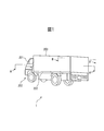
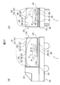
- FIG. 1 is a perspective view of a balloon carrying device according to a first embodiment.
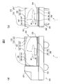
- 2A is a cross-sectional view taken along the line AA ′ in FIG. 1
- FIG. 2B is a cross-sectional view taken along the line BB ′ in FIG.
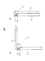
- It is a perspective view of the 1st side movement mechanism shown in Drawing 2 (b).
- It is a side view explaining operation
- (a) is a figure which shows the state before a 1st upper surface movement mechanism rotates a 1st upper surface
- FIG. 8 is a diagram illustrating a state after the first upper surface moving mechanism rotates the first upper surface.
- It is a perspective view of the balloon carrying device which is releasing a balloon.
- (D) shows the fourth operation
- (e) shows the fifth operation
- (f) shows the sixth operation
- (g) shows the seventh operation
- (H) shows the eighth operation
- (i) shows the ninth operation.
- (D) shows the fourth operation, (e) shows the fifth operation, (f) shows the sixth operation, (g) shows the seventh operation, (h) Indicates the eighth operation, and (i) indicates the ninth operation.
- (A) is a schematic sectional drawing which shows the state which discharges a balloon from the balloon storage box mounted in the balloon conveyance apparatus
- (b) is the outline which shows the 1st state in which the released balloon received the wind. It is sectional drawing
- (c) is a schematic sectional drawing which shows the 2nd state to which the released balloon received the wind
- (d) is a schematic sectional drawing which shows the state which fell the side of the balloon storage box.
- (E) is a schematic sectional view showing a state where the height of the side surface of the balloon storage box is lowered. It is a perspective view of the balloon conveying apparatus which concerns on 2nd Embodiment.
- (A) is a cross-sectional view taken along the line AA ′ in FIG.
- FIG. 11 is a perspective view of the balloon mooring device shown in FIG. 10, (a) a perspective view of the balloon mooring device immediately after the balloon is released, and (b) a perspective view of the balloon mooring device mooring the balloon. . It is a perspective view of the balloon carrying apparatus which is mooring the balloon shown in FIG.
- FIG. 11 is a schematic cross-sectional view from the right direction showing the operation when the balloon is released in the balloon carrying device shown in FIG.
- FIG. 10 It is a schematic plan view which shows operation
- the balloon storage box according to the first embodiment has side surfaces that are arranged along the periphery of the bottom surface and at least a part of which can move outward.
- the balloon storage box according to the first embodiment moves the movable part of the side surface to the outside and fills the distance between the opposing side surfaces when filling the balloon stored inside with helium gas.
- the volume of the balloon storage box is increased so that the balloon filled with helium gas can be stored.
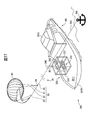
- FIG. 1 is a perspective view of a balloon carrying device equipped with a balloon storage box.
- Balloon carrier 1 has cargo vehicle 202 and balloon storage box 203 mounted on cargo vehicle 202.
- the cargo vehicle 202 has an occupant room 221, also called a cabin, and a loading platform 222 disposed behind the occupant room 221.
- the width of the freight vehicle 202 is 2.5 meters or less so that it can pass along a road.
- FIG. 2A is a cross-sectional view taken along the line AA ′ in FIG. 1
- FIG. 2B is a cross-sectional view taken along the line BB ′ in FIG.
- the balloon storage box 203 has a rectangular bottom surface 230, a side surface 240 whose lower side is disposed along the periphery of the bottom surface 230, and an upper surface 250 that is disposed so as to contact the upper side of the side surface.
- the balloon storage box 203 includes a side surface moving mechanism 260 that moves a part of the side surface from the periphery of the bottom surface 230 toward the outer periphery, and an upper surface moving mechanism 270 that rotates the upper surface 250 around one side of the upper surface 250.
- the balloon mooring device 3 is fixed to the surface of the bottom surface 230.
- the balloon mooring device 3 includes a balloon 90, a mooring device 95, and a balloon 90 connected to a winding device (not shown) disposed inside the mooring device 95 via a mooring line.
- the balloon 90 is arranged in a state where the upper surface of the mooring device 95 is hardly filled with helium gas.
- the width of the balloon storage box 203 is equal to or less than the width of the cargo vehicle 202. That is, the width of the balloon storage box 203 is 2.5 meters or less. By setting the width of the balloon storage box 203 to 2.5 meters or less, the cargo vehicle 202 can travel on the road with the balloon storage box 203 mounted thereon.
- the side surface 240 extends upward from a rectangular first side surface 241 that extends upward from the first side of the bottom surface 230 that extends backward from the passenger compartment 221 and a second side that faces the first side of the bottom surface 230.
- a second side surface 242 having a square shape.
- the side surface 240 has a rectangular third side surface 243 extending upward from the third side extending from the rear vertex of the first side of the bottom surface 230 to the rear vertex of the second side, and the front side of the first side of the bottom surface 230.
- a rectangular fourth side surface 244 extending upward from the fourth side extending from the apex to the apex in front of the second side.
- the upper surface 250 has a first upper surface 251 extending in a direction perpendicular to the first side surface 241 from the upper side of the first side surface 241, and a second upper surface 252 extending in a direction perpendicular to the second side surface 242 from the upper side of the second side surface 242. And a third upper surface 253 extending in a direction perpendicular to the third side surface 243 from the upper side of the third side surface 243.
- the first upper surface 251 and the second upper surface 252 are disposed so that their tip portions overlap each other, and the third upper surface 253 is disposed below the first upper surface 251 and the second upper surface 252.
- the side surface moving mechanism 260 includes a first side surface moving mechanism 261 that moves the first side surface 241, a second side surface moving mechanism 262 that moves the second side surface 242, and a third side surface moving mechanism 263 that moves the third side surface 243.
- FIG. 3 is a perspective view of the first side surface moving mechanism 261.
- FIG. 3 shows an example of the configuration of the first side surface moving mechanism 261, and the configuration of the first side surface moving mechanism 261 is not limited to the configuration shown in FIG. Since each of the second side surface moving mechanism 262 and the third side surface moving mechanism 263 has the same configuration and function as the first side surface moving mechanism 261, detailed description of the second side surface moving mechanism 262 and the third side surface moving mechanism 263 is provided. Is omitted.
- the first side surface moving mechanism 261 includes a first arm portion 2611 to a third arm portion 2613, a rack 2614, a pinion 2615, and a drive portion 2616.
- One end of each of first to third arm portions 2611 to 2613 and rack 2614 is joined to first side surface 241.
- the pinion 2615 is fitted to the rack 2614 and moves on the first side surface 241 joined to the pinion 2615 in accordance with the rotation of the driving unit 2616.
- the drive unit 2616 includes a motor and a speed reducer that are powered by a power source (not shown). When the drive unit 2616 receives a first side movement instruction indicating movement of the first side 241, the drive unit 2616 starts to rotate, Stop rotation after a while.
- the rack 2614, the pinion 2615, and the drive unit 2616 of the first side movement mechanism 261 may be an integrated linear movement mechanism that is also referred to as a linear head.
- the first side surface moving mechanism 261 moves the first side surface 41 outward from the first side of the bottom surface 230 extending from the front to the rear.
- the second side surface moving mechanism 262 moves the first side surface 241 outward from the second side facing the first side of the bottom surface 230.
- the second side surface moving mechanism 262 moves the first side surface 241 outward from the second side facing the first side of the bottom surface 230.
- the third side surface moving mechanism 263 moves outward from the third side extending from the vertex at the rear of the first side of the bottom surface 230 to the vertex at the rear of the second side.
- the upper surface moving mechanism 270 includes a first upper surface moving mechanism 271 that rotates the first upper surface 251, a second upper surface moving mechanism 272 that rotates the second upper surface 252, and a third upper surface moving mechanism 273 that rotates the third upper surface 253.
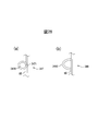
- FIG. 4 is a side view for explaining the operation of the first upper surface moving mechanism 271.
- FIG. 4A is a diagram showing a state before the first upper surface moving mechanism 271 rotates the first upper surface 251.
- FIG. 6B is a diagram illustrating a state after the first upper surface moving mechanism 271 rotates the first upper surface 251.
- FIG. 4 shows an example of the configuration of the first upper surface moving mechanism 271, and the configuration of the first upper surface moving mechanism 271 is not limited to the configuration shown in FIG. Since each of the second upper surface moving mechanism 272 and the third upper surface moving mechanism 273 has the same configuration and function as the first upper surface moving mechanism 271, a detailed description of the second upper surface moving mechanism 272 and the third upper surface moving mechanism 273 is provided. Is omitted.
- the first upper surface moving mechanism 271 includes a rotating unit 2711 and a driving unit 2712.
- the rotating unit 2711 connects the first side surface 241 and the first upper surface 251.
- the drive unit 2712 is a conductive rotation mechanism that is also called cobolane, and is formed of a motor and a speed reducer that are supplied with power from a power source (not shown).
- the driving unit 2712 rotates the rotating unit 2711, the first upper surface 251 connected to the first side surface 241 rotates and the first upper surface 251 arranged so as to extend in the horizontal direction extends in the vertical direction. Move to stretch.
- an electric winch winding device is disposed to moor the balloon 90 which is sufficiently filled with helium gas and can be raised.
- the balloon 90 filled with helium gas rises into the air according to the unwinding amount of the mooring line from the winding apparatus,
- the balloon 90 descends from the air according to the winding amount. Since the mooring device 95 is fixed to the bottom surface 230 of the balloon storage box 203, it is not necessary to fix the mooring line directly to the ground with an anchor or the like.
- Balloon 90 has an outer bag formed of a rigid, lightweight and air-permeable material such as synthetic fiber, and a helium storage bag filled with helium gas. Since the balloon 90 has a double structure of a helium storage bag and an air storage bag and an outer bag, the outer bag does not need to be formed of a material having a gas barrier property.
- the balloon 90 is an example of this configuration, and can be a balloon composed of only a helium storage bag, and is not limited to that configuration.
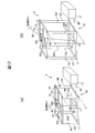
- FIG. 5 is a perspective view of the balloon carrying device 1 that is releasing the balloon 90.
- the balloon 90 includes a mooring line 80 formed from a first mooring line 81 to a third mooring line 83 and a main mooring line 85 connected to the first mooring line 81 to the third mooring line 83 via a node 84. Is moored by a winding device disposed inside the mooring device 95.
- each of the first side surface moving mechanism 261 to the third side surface moving mechanism 263 moves each of the first side surface 241 to the third side surface 243 before releasing the balloon 90.
- the first upper surface moving mechanism 271 to the third upper surface moving mechanism 273 rotate the first upper surface 251 to the third upper surface 253, and the first side surface 241 to the third side surface 241.
- the balloon storage box 203 can secure a volume capable of storing the balloon 90.
- the balloon storage box 203 has a bottom surface 230 on which a mooring device 95 for mooring the balloon 90 is disposed by rotating the first upper surface 251 to the third upper surface 253 to a position facing the first side surface 241 to the third side surface 243. An opening through which the balloon 90 can be released can be secured above.
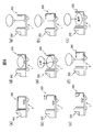
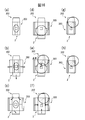
- FIGS. 6 to 8 are schematic views showing the operation of the balloon carrier device 1 when the balloon 90 is released.
- 6 is a cross-sectional view of the balloon carrier 1 from the right side
- FIG. 7 is a cross-sectional view of the balloon carrier 1 from the rear
- FIG. 7 is a plan view of the balloon carrier 1 from the rear.
- 6 (a), 7 (a) and 8 (a) show the first state
- FIGS. 6 (b), 7 (b) and 8 (b) show the second state following the first state. Show.
- FIGS. 6 (c) to 6 (h), 7 (c) to 7 (h) and 8 (c) to 8 (h) shows a state following the previous state
- FIG. ), 7 (i) and 8 (i) show a ninth state following the eighth state.
- the balloon carrier 1 is stopped at a desired mooring point (see FIGS. 6 (a), 7 (a) and 8 (a)).
- the side surface 240 of the balloon storage box 203 is disposed along the periphery of the bottom surface 230, and the top surface 250 is disposed at a position facing the bottom surface 230.
- the balloon 90 stored in the balloon storage box 203 is not filled with helium gas.
- the balloon 90 may be filled with helium gas to a size that can be stored in the balloon storage box 203.
- the side surface moving mechanism 260 moves the side surface 240 from the periphery of the bottom surface 230 to the outside, and widens the distance between the opposing side surfaces (FIGS. 6B, 7B, and 8B). See).
- the first side surface moving mechanism 261 moves the first side surface 241 outward from the end of the bottom surface 230
- the second side surface moving mechanism 262 moves the second side surface 242 outward from the end of the bottom surface 230 to move the third side surface.
- the mechanism 263 moves the third side surface 243 from the end of the bottom surface 230 to the outside.
- Each of the first side surface moving mechanism 261 to the third side surface moving mechanism 263 moves each of the first side surface 241 to the third side surface 243 from the periphery of the bottom surface 230 to the outside, so that the volume of the balloon storage box 203 is increased.
- the first side surface 241 to the third side surface 243 become larger than before the movement.
- the upper surface moving mechanism 270 rotates the upper surface 250 about one side of the upper surface 250 so as to move so that the upper surface 250 faces the side surface 240 (FIGS. 6C, 7C, and 8). see c)).
- the first upper surface moving mechanism 271 rotates the first upper surface 251 around the side of the first upper surface 251 in contact with the first side surface 241, and the second upper surface moving mechanism 272 moves the side of the second upper surface 252 in contact with the second side surface 242.
- the second upper surface 252 is rotated as an axis.
- the third upper surface moving mechanism 273 rotates the third upper surface 253 with the side of the third upper surface 253 in contact with the third side surface 243 as an axis.
- the first upper surface moving mechanism 271 to the third upper surface moving mechanism 273 rotate the first upper surface 251 to the third upper surface 253, respectively, and the first upper surface 251 to the third upper surface 253 are moved to the first side surfaces 241 to 241, respectively. It moves to a position facing each of the third side surfaces 243.
- the balloon 90 filled with helium gas inside the balloon storage box 203 is not moved to the outside of the balloon storage box 203. The balloon can be released from the inside of the balloon storage box 203.
- the balloon 90 is filled with helium gas stored in a gas storage container (not shown) (see FIGS. 6 (d), 7 (d) and 8 (d)).
- the balloon 90 filled with helium gas is held inside the balloon storage box 203 until the mooring line is unwound from the winding device arranged inside the mooring device 95.
- the balloon 90 is released and rises (see FIGS. 6 (e), 7 (e) and 8 (e)).
- the balloon 90 rises.
- the height of the balloon 90 reaches a desired height, the unwinding of the winding device disposed inside the mooring device 95 is terminated.
- the side surface moving mechanism 260 moves the side surface 240 disposed outside the periphery of the bottom surface 230 toward the periphery of the bottom surface 230 (see FIGS. 6 (f), 7 (f), and 8 (f)).
- the first side surface moving mechanism 261 moves the first side surface 241 to the end of the bottom surface 230
- the second side surface moving mechanism 262 moves the second side surface 242 to the end of the bottom surface 230
- the third side surface moving mechanism 263 is the first side surface moving mechanism 263.
- the three side surfaces 243 are moved to the end of the bottom surface 230.
- the side surface 240 is disposed along the periphery of the bottom surface 230 (see FIGS. 6 (g), 7 (g), and 8 (g)).
- the side surface moving mechanism 260 moves the side surface 240 from the periphery of the bottom surface 230 toward the outside (FIGS. 6H, 7H, and 8H). )).
- the first side surface moving mechanism 261 moves the first side surface 241 outward from the end of the bottom surface 230
- the second side surface moving mechanism 262 moves the second side surface 242 outward from the end of the bottom surface 230 to move the third side surface.
- the mechanism 263 moves the third side surface 243 from the end of the bottom surface 230 to the outside.
- the balloon 90 is lowered and accommodated (see FIGS. 6 (i), 7 (i), and 8 (i)).
- the balloon 90 descends.
- the winding device disposed inside the mooring device 95 finishes winding the main mooring line 85.
- the balloon 90 is filled with helium gas inside the balloon storage box 203.
- the balloon 90 can be filled with helium gas inside the balloon storage box 203, the balloon 90 being filled with helium gas can suppress the influence of the wind, and the attitude of the balloon 90 changes to change the helium gas. There is little risk of hindering the filling operation.
- the balloon 90 is moored by the mooring device 95 fixed to the bottom surface 230, it is not necessary to fix the mooring line directly to the ground by an anchor or the like.
- the balloon storage box 203 includes the upper surface moving mechanism 270 that rotates the upper surface 250 about one side of the upper surface 250 and moves the upper surface 250 so as to face the side surface 240.
- An opening is formed above the bottom surface 230 of the balloon storage box 203.
- the air from the side surface is not received inside the balloon storage box by returning the side surface 240 to the original position while the balloon 90 is being released.
- people can be prevented from entering the inside of the balloon storage box from the side.
- the balloon carrier 1 since the balloon carrier 1 according to the first embodiment includes the balloon storage box 203 and the cargo vehicle 202 on which the balloon storage box 203 is mounted, the balloon carrier 1 can carry the balloon 90 to a desired place. In addition, the balloon 90 can be quickly released at the transportation destination.
- the cargo vehicle 202 since the width of the cargo vehicle 202 and the width of the balloon storage box 203 are 2.5 meters or less, the cargo vehicle 202 is mounted with the balloon storage box 203 mounted thereon. Can travel through the road.
- the balloon storage box 203 can move on the three side surfaces of the first side surface 241, the second side surface 242, and the third side surface 243, but may have a structure in which one or two side surfaces are movable. Well, all four sides may be movable. For example, when the length of the balloon storage box 203 is longer than the diameter of the balloon 90 filled with helium gas, the third side surface 243 may not be movable. In addition, either the first side surface 241 or the second side surface 242 may be movable.
- the bottom surface 230 of the balloon storage box 203 is square, but may have other shapes such as a circle and a triangle. The balloon storage box 203 may not be mounted on the cargo vehicle 202.
- the three upper surfaces of the first upper surface 251, the second upper surface 252, and the third upper surface 253 are rotatable, but one or two side surfaces are rotatable.
- the upper surface 250 may not be rotatable.
- the balloon storage box 203 when the side surface 240 is moved from the periphery of the bottom surface 230 to the outside, the first side surface 241 and the fourth side surface 244 are between the first side surface 241 and the third side surface 243. A gap is formed between the second side surface 242 and the third side surface 243, and between the second side surface 242 and the fourth side surface 244.
- the balloon storage box has the first side surface 241 to the fourth side surface. It may further have a side surface for a gap that can be arranged in the gap formed between 244. Since the balloon storage box has a gap side surface that can be disposed in the gap formed between the first side surface 241 to the fourth side surface 244, it is possible to prevent a person from entering the inside of the balloon storage box 203. become.
- the balloon storage box according to the first embodiment and the balloon transport device for transporting the balloon storage box according to the first embodiment have been described above with reference to FIGS.
- a balloon mooring device according to the second embodiment, a modification thereof, and a balloon storage box for housing the balloon mooring device according to the second embodiment will be described.
- the balloon receives a wind and moves from a position immediately above the balloon mooring device.
- the main mooring line 85 may come into contact with the upper surface of the protective wall.
- the main mooring line 85 may be rubbed and gradually worn and cut.
- various obstacles may be arranged around the balloon mooring device, and these obstacles may come into contact with the mooring line.
- the balloon mooring apparatus described with reference to FIGS. 9 to 18 solves this problem, and is arranged around the balloon mooring apparatus when the balloon mooring apparatus moors the balloon through the mooring line.
- An object of the present invention is to provide a balloon mooring device that has a low possibility of a mooring line coming into contact with an obstacle.
- the inventor of the present application transports a balloon to the vicinity of a base station where a communication failure has occurred by using a balloon transport device equipped with a balloon storage box that can store the balloon, and stores the balloon. It was found that the upper surface of the box was opened and the balloon was released from the balloon storage box with the upper surface opened. By transporting the balloon with the balloon transporting device and releasing the balloon from the balloon storage box transported with the balloon transporting device, the balloon can be released quickly and easily.
- FIG. 9A is a schematic cross-sectional view showing a state in which a balloon is released from a balloon storage box mounted on the balloon carrying device
- FIG. 9B is a first view in which the released balloon receives wind
- FIG. 9C is a schematic cross-sectional view showing a second state in which a released balloon receives wind.
- the balloon carrying device 901 includes a freight vehicle 902 provided with tires 9020 and a loading platform 9021, and a balloon storage box 903 provided on the freight vehicle 902 and provided with a side surface 9031.
- the balloon storage box 903 is mounted with a mooring device 910 including a winding device and a balloon 990 connected to the mooring device 910 via a mooring line 980.
- the balloon 990 transported by the balloon transport device 901 is moored, the balloon 990 is released from the balloon storage box 903 whose upper surface is opened. Since the balloon 990 cannot be released under a strong wind, the balloon 990 is released when there is almost no wind or under a slight wind.
- the released balloon 990 is located immediately above the mooring device 910 immediately after being released.
- the balloon 990 moves from a position immediately above the mooring device 910, and the mooring line inclination angle ⁇ i between the mooring wire 980 connecting the balloon 990 and the mooring device 910 and the vertical direction increases. . If the wind speed further increases, the mooring line 980 may come into contact with the side surface 9031. In order to prevent the mooring line 980 from contacting the side surface 9031, in order to prevent the mooring line 980 from contacting the side surface 9031, it is conceivable to tilt the side surface and reduce the height of the side surface.
- FIG. 9D is a schematic cross-sectional view showing a state in which the side surface of the balloon storage box is tilted
- FIG. 9E is a schematic cross-sectional view showing a state in which the height of the side surface of the balloon storage box is lowered.
- the balloon storage box 913 mounted on the balloon carrying device 911 is tilted on the side surface 9032 by rotating the side surface 9032 outward.
- the balloon storage box 923 mounted on the balloon carrying device 921 has the side surface 9033 bent to reduce the height of the side surface 9033. Even when the balloon 990 receives strong wind and the mooring line inclination angle ⁇ i is maximized by depressing the side surface 9032 of the balloon storage box 913 or lowering the height of the side surface 9033 of the balloon storage box 923, the mooring line 980 Contact with the side surface 9031 can be prevented.
- the balloon anchoring device lowers the position at which the balloon anchoring device anchors the balloon until the balloon is released, and the position at which the balloon anchoring device anchors the balloon while the balloon is anchored.
- the balloon mooring device includes a locking portion that locks the mooring line wound from the winding device, and a first position and a second position that is higher than the first position. And a supporting member that movably supports the locking portion. When the balloon is filled with gas and released, the balloon anchoring device anchors the balloon at the first position where the balloon filling operation is easy.
- the balloon anchoring device according to the second embodiment anchors the balloon at the second position, which is a position higher than the first position. Since the balloon mooring device according to the second embodiment moores the balloon at a higher position during the mooring of the balloon, the mooring line is less likely to come into contact with the side surface during mooring of the balloon.
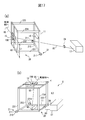
- FIG. 10 is a perspective view of a balloon carrying device according to the second embodiment equipped with a balloon storage box.
- the balloon transport device 2 includes a cargo vehicle 202 and a balloon storage box 203 mounted on the cargo vehicle 202. Since the freight vehicle 202 and the balloon storage box 203 have the same configuration and function as the freight vehicle and the balloon storage box having the same reference numerals described with reference to FIGS. 1 and 2, etc., detailed description is omitted here. .
- FIG. 11A is a cross-sectional view taken along line AA ′ in FIG. 10, and FIG. 11B is a cross-sectional view taken along line BB ′ in FIG.
- a balloon anchoring device 4 having a support frame 10, a winding device 17, and a balloon 90 connected to the winding device 17 via a mooring line 80 including a main mooring line 85 is disposed. Is done.
- the support frame 10 and the winding device 17 are fixed to the bottom surface 230 of the balloon storage box 203, and the balloon 90 is mounted on the upper surface of the support frame 10 in a state where the helium gas is hardly filled.
- FIG. 12 (a) is a perspective view of the balloon anchoring device 4 immediately after the balloon 90 is released
- FIG. 12 (b) is a perspective view of the balloon anchoring device 4 that is anchoring the balloon 90.
- the support frame 10 includes a bottom frame portion 11, an upper frame portion 12, first telescopic legs 131 to fourth telescopic legs 134, first fixing members 141 to fourth fixing members 144, a cable guide device 15, and rollers. 16.
- Each of the bottom frame portion 11 and the top frame portion 12 is a frame-like member formed of steel, and the bottom frame portion 11 is fastened to the bottom surface 230 of the balloon storage box 203 by a fastening member (not shown). Supports the guide device 15 by the guide device support parts 121 and 122 extending from the opposite sides.
- Each of the first telescopic legs 131 to the fourth telescopic legs 134 is a member formed of a steel material that can expand and contract between a first length L1 and a second length L2 that is longer than the first length L1.
- first length L1 a first length L1 and a second length L2 that is longer than the first length L1.
- the lengths of the first extendable leg 131 to the fourth extendable leg 134 are the same as the first length L1 until the balloon 90 is filled with helium after being moved by the balloon carrier device 2 and the balloon 90 is released. To do.
- the lengths of the first extendable leg 131 to the fourth extendable leg 134 are set to the second length L2 while the balloon 90 is moored.
- the second length L2 is defined by the height of the side surface 240 of the balloon storage box 203 and the distance between the rope guiding device 15 and the side surface 240.
- the second length L2 is the difference between the second length L2 corresponding to the height of the rope guiding device 15 and the height of the side surface 240. Is defined to be longer than the distance between the cable guide device 15 and the side surface 240.
- the cable guiding device 15 is a four-sided roller having two pairs of rollers arranged in a square shape, and a rope passage 150 is formed inside the four-sided roller.
- the rope guiding device 15 is configured so that when the main mooring line 85 is unwound from the winding device 17 as the balloon 90 is raised and lowered, and when the main mooring line 85 is taken up by the winding device 17, The main mooring line 85 passing through is slidably guided.
- the cable guiding device 15 functions as a locking portion that locks the balloon 90 at the cable passing port 150 via the main mooring cable 85 that moves within a moving range defined by the cable passing port 150.
- the roller 16 is a rotatable cylindrical member fixed to the bottom frame portion 11 and refracts the main mooring line 85 extending in the horizontal direction from the winding device 17 in the vertical direction in which the line passing port 150 is located.
- the winding device 17 includes a winding drum (not shown) that winds up the main mooring line 85 and a winding motor (not shown) that rotates the winding drum at a predetermined speed.
- the winding motor rotates the winding drum in the unwinding direction when unwinding the main mooring line 85, and winds the winding drum in the winding direction opposite to the unwinding direction when winding the main mooring line 85. Rotate the drum.
- the winding device 17 fixes the length of the main mooring line 85 to a constant length in order to keep the position of the balloon 90 constant while the balloon 90 is moored.
- the balloon anchoring device 4 locks the balloon 90 by making the lengths of the first extendable leg 131 to the fourth extendable leg 134 longer than before releasing the balloon 90 while the balloon 90 is being moored. Therefore, the mooring line is less likely to come into contact with the side surface 240.
- FIG. 13 is a perspective view of the balloon carrying device 2 that is mooring the balloon 90.
- the first side surface 241 to the third side surface 243 are moved from the periphery of the bottom surface 230 to the outside, but when the balloon 90 is moored, the first side surface 241 is moved.
- the third side surface 243 is preferably located around the bottom surface 230.
- each of the first telescopic legs 131 to the fourth telescopic legs 134 of the support frame 10 is longer than the first length L1 to the first length L1.
- the first fixing member 141 to the fourth fixing member 144 are fixed in a state where the length L2 is extended to 2.
- the lengths of the first telescopic legs 131 to the fourth telescopic legs 134 of the support gantry 10 are fixed at the second length L2, so the balloon 90 is moved by the wind and moored. There is a low risk that the main mooring line 85 will come into contact with the side surface 240 even if the cable inclination angle increases.
- FIGS. 14 to 16 are schematic diagrams showing the operation of the balloon carrying device 2 when the balloon 90 is released.
- 14 is a cross-sectional view of the balloon carrier 2 from the right side
- FIG. 15 is a cross-sectional view of the balloon carrier 2 from the rear
- FIG. 16 is a plan view of the balloon carrier 2 from the rear.
- 14 (a), 15 (a) and 16 (a) show the first state
- FIGS. 14 (b), 15 (b) and 16 (b) show the second state following the first state. Show.
- FIGS. 14 (c) to 14 (g), 15 (c) to 15 (g) and 16 (c) to 16 (g) shows a state following the previous state
- FIG. ) 15 (h) and 16 (h) indicate an eighth state following the seventh state.
- the balloon 90 is released and rises (see FIGS. 14 (e), 15 (e) and 16 (e)).
- the balloon mooring device 4 unwinds the main mooring line 85 from the winding device 17, the balloon 90 rises.
- the balloon mooring device 4 finishes unwinding the main mooring line 85.
- the side surface moving mechanism 260 moves the side surface 240 arranged outside the periphery of the bottom surface 230 toward the periphery of the bottom surface 230 (see FIGS. 14 (f), 15 (f) and 16 (f)).
- the first side surface moving mechanism 261 moves the first side surface 241 to the end of the bottom surface 230
- the second side surface moving mechanism 262 moves the second side surface 242 to the end of the bottom surface 230
- the third side surface moving mechanism 263 is the first side surface moving mechanism 263.
- the three side surfaces 243 are moved to the end of the bottom surface 230.
- the side surface 240 is disposed along the periphery of the bottom surface 230 (see FIGS. 14 (g), 15 (g), and 16 (g)). At this time, the lengths of the first telescopic legs 131 to the fourth telescopic legs 134 of the support base 10 are the first length L1.
- each of the first telescopic legs 131 to the fourth telescopic legs 134 of the support base 10 is extended from the first length L1 to the second length L2 longer than the first length L1, and then the first fixing member. 141 to the fourth fixing member 144 (see FIGS. 14 (h), 15 (h) and 16 (h)).
- FIG. 17 is a diagram showing a balloon mooring device according to a first modification
- FIG. 17A is a perspective view of the balloon mooring device according to the first modification immediately after the balloon 90 is released.
- (B) is a perspective view of the balloon mooring device according to the first modified example in which the balloon 90 is moored.
- the balloon mooring device 5 according to the first modification differs from the balloon mooring device 4 in that the fixing member 24 is arranged. Further, the balloon anchoring device 5 has a rotating portion 21 instead of the support base 10 and a support in which the first leg 231 to the fourth leg 234 are arranged instead of the first extendable leg 131 to the fourth extendable leg 134. It differs from the balloon mooring apparatus 4 to have the gantry 20. Therefore, hereinafter, the rotating unit 21, the first leg 231 to the fourth leg 234, and the fixing member 24, which are different from the balloon mooring device 4, will be described. The constituent elements other than the rotating unit 21, the first leg 231 to the fourth leg 234, and the fixing member 24 of the balloon mooring device 5 have the same configuration and function as the balloon mooring device 4, and therefore detailed description thereof will be given here. Omitted.
- the rotating unit 21 is located at the base of the support frame 20, and is fixed to the bottom surface 230 of the balloon storage box 203 so that the shaft 210 is joined to one side of the bottom frame 11 and the shafts 210 are disposed at both ends of the shaft 210 to be rotatable.
- the support base 20 is rotatably supported on the bottom surface 230 of the balloon storage box 203.
- Each of the first leg 231 to the fourth leg 234 is a rod-shaped member made of steel, and one end is connected to the bottom frame portion 11 and the other end is connected to the upper frame portion 12.
- the fixing member 24 is an arcuate member whose one end is rotatably fixed to the bottom surface 230 of the balloon storage box 203 and whose other end can be fastened to the bottom surface 230 of the balloon storage box 203 with a fastening member (not shown).
- the support base 20 has a fall position where the first leg 231 and the second leg 232 are in contact with the bottom surface 230 of the balloon storage box 203, and the bottom frame portion 11 as shown in FIG.
- the balloon storage box 203 can rotate between the standing position in contact with the bottom surface 230 of the balloon storage box 203.
- the fixing member 24 fixes the side facing the side where the shaft 210 of the bottom frame portion 11 is joined to the bottom surface 230 of the balloon storage box 203.
- the fixing member 24 fixes one side of the bottom frame portion 11, the support frame 20 is not rotated by the rotating unit 21 when the support frame 20 is in the upright position.
- the support frame 20 is moved to the overturning position until the balloon 90 is filled with helium and the balloon 90 is released by the balloon carrier 2. Further, the support frame 20 is placed in the standing position while the balloon 90 is moored. When the support frame 20 is in the fall position, the height from the bottom surface 230 of the balloon storage box 203 to the upper portion of the rope passage port 150 through which the main mooring line 85 passes becomes the first length L1. When the support frame 20 is in the standing position, the height from the bottom surface 230 of the balloon storage box 203 to the top surface of the rope guiding device 15 becomes the second length L2 that is longer than the first length L1.
- FIG. 18 is a view showing a balloon mooring device according to a second modification
- FIG. 18 (a) is a perspective view of the balloon mooring device according to the first modification immediately after the balloon 90 is released.
- (B) is a perspective view of a balloon anchoring device according to a second modified example in which the balloon 90 is moored.
- the balloon mooring device 6 according to the second modification is different from the balloon mooring device 5 according to the first modification in that it does not have a rotating part and has a fixing member 324 instead of the fixing member 24. Further, the balloon mooring device 5 is different from the balloon mooring device 5 in that the support frame 30 includes the first rail 321, the second rail 322, and the first wheel 36 to the fourth wheel 39 instead of the support frame 20. Therefore, hereinafter, the fixing member 324, the first rail 321, the second rail 322, and the first wheel 36 to the fourth wheel 39, which are different from the balloon mooring device 5, will be described.
- the constituent elements other than the fixing member 324, the first rail 321, the second rail 322, and the first wheel 36 to the fourth wheel 39 of the balloon mooring device 6 have the same configuration and function as the balloon mooring device 5. Detailed description is omitted here.
- the first rail 321 and the second rail 322 have a concave cross section and are arranged in parallel with a distance of approximately the same length as the length between the first leg 231 and the second leg 232.
- Each of the first wheel 36 to the fourth wheel 39 is a pair of wheels that can be disposed in the recesses of the first rail 321 and the second rail 322 and a shaft that is joined to the support frame 30 and rotatably supports the pair of wheels. And have.
- the first wheel 36 and the second wheel 37 are disposed in the recesses of the first rail 321 and the second rail 322 when the support frame 30 is in the fall position shown in FIG.
- the 3rd wheel 38 and the 4th wheel 39 are arrange
- the fixing member 24 is an arcuate member whose both ends can be fastened to the bottom surface 230 of the balloon storage box 203 by a fastening member (not shown).
- the fixing member 24 fixes one side of the bottom frame portion 11 to the bottom surface 230 of the balloon storage box 203 when the support frame 30 is in the standing position.
- the first rail 321, the second rail 322, and the first wheel 36 to the fourth wheel 39 are the bottom frame part 11, the upper plate part, and the first leg 231 to the fourth leg 234, and the support frame 30 is in the fall position.
- a moving mechanism is formed that can rotate to the standing position while moving the support frame 30 in the horizontal direction.
- an operator slides the first wheel 36 to the fourth wheel 39 on the first rail 321 and the second rail 322 and moves the upper frame portion 12 upward. It can rotate from the fall position shown to a) to the standing position shown in FIG.18 (b). Specifically, after releasing the balloon 90, the worker slides the support frame 30 in the direction indicated by the arrow A in FIG. 18A and lifts the upper frame portion 12 upward. When the upper frame portion 12 is lifted upward, the first wheel 36 and the second wheel 38 are sequentially separated from the first rail 321 and the second rail 322, and then the third wheel 38 and the fourth wheel 39 are sequentially turned to the first rail. 321 and the second rail 322 are disposed.
- the support frame 30 is rotated from the fall position to the standing position. Then, the operator fixes the support frame 30 in the standing position to the bottom surface 230 of the balloon storage box 6 at a predetermined position by the fixing member 324 and sets the support frame 30 in the standing position while the balloon 90 is moored. .
- the support frame 30 is in the overturned position, the height from the bottom surface 230 of the balloon storage box 6 to the upper part of the rope passage port 150 through which the main mooring line 85 passes becomes the first length L1.
- the support frame 30 is in the standing position, the height from the bottom surface 230 of the balloon storage box 6 to the top surface of the rope guiding device 15 becomes the second length L2 that is longer than the first length L1.
- the balloon mooring device guides a rope between a rope guiding device that functions as a locking portion that locks the mooring rope and a first position and a second position that is higher than the first position.
- a support member for movably supporting the apparatus Specifically, the balloon mooring device 4 sets the length of the first telescopic legs 131 to the fourth telescopic legs 134 that can be expanded and contracted to a second length L2 that is longer than the first length L1 while the balloon is moored.
- the balloon anchoring device 5 that fixes the height from the bottom surface 230 of the rope guiding device 15 to the second height by fixing the support frame 20 to the overturning position until the balloon is released, while the balloon is being moored.
- the support gantry 20 is fixed at the standing position where the height of the cable guiding device 15 is higher than that at the falling position.
- the balloon mooring device 6 keeps the support frame 30 in the fall position until the balloon is released, and after releasing the balloon, the height of the balloon anchor device 6 is determined by sliding the support frame 30 and moving the rope guiding device 15 upward.
- the support frame 30 is fixed at a standing position higher than that at the falling position.
- the support frame 30 is slid to bring the support frame 30 into the upright position, so that the area occupied by the balloon mooring device is smaller than the balloon mooring device 4 according to the first modification.
- the support frame can be erected with a smaller force.
- the balloon mooring device according to the second embodiment may have another structure that supports the rope guiding device movably between the first position and a second position that is higher than the first position.
- the support member that supports the cable guide device may have bellows-like extendable legs in which the ends of a plurality of extendable members each composed of two plate-like members that are rotatably connected at the center are connected to each other. Good.
- the rope guide device 15 in which the rope passage port 150 through which the mooring line passes functions as a locking portion that locks the balloon 90.
- the locking portion is another form that can lock the mooring end of the main mooring line 85 connected to the balloon 90 within a certain range, such as fixing the main mooring line 85 to the upper frame portion 12 of the support frame 10. It is good.
- the balloon mooring device according to the second embodiment is used by being placed inside the balloon storage box, but may be used in an environment where obstacles such as a protective wall are placed around. .
- the balloon storage box 203 is mounted on a cargo vehicle and can be moved, the balloon storage box according to the second embodiment may be used by being fixed at a predetermined place.
- the balloon mooring device according to the second embodiment, its modification, and the balloon storage box for housing the balloon mooring device according to the second embodiment have been described with reference to FIGS.
- the balloon mooring device according to the third embodiment and its modification, and the balloon carrying device and the balloon mooring ship equipped with the balloon mooring device according to the third embodiment will be described.
- the motor of the wind-up device of the balloon mooring device for mooring the balloon is subjected to a torque corresponding to the tension generated in the mooring line when the balloon receives wind in order to maintain the moored balloon at a certain position. Even in such a case, it is necessary to have a sufficiently large torque so that no slip occurs.
- the torque applied to the motor of the winder when the balloon receives wind increases in proportion to the area of the surface where the balloon receives wind and the square of the wind speed. Therefore, the larger the balloon and the higher the wind speed. growing. For this reason, it is necessary to increase the size of the balloon in order to increase the torque of the motor of the winding device as the size of the balloon increases. If the motor of the winding device is enlarged, the manufacturing cost of the balloon mooring device increases, and the weight of the balloon mooring device increases, which may increase the transportation cost of the balloon mooring device.
- an anti-rotation lock that prevents the drum of the winding device from rotating by a torque corresponding to the tension generated in the mooring line may be arranged in the winding device.
- the tension generated in the mooring line is applied to the drum, so that the winding device is used to improve the strength of the winding device drum instead of increasing the winding device motor. It is necessary to improve the strength of the steel material forming the drum and to increase the size. Even when the anti-rotation lock is used, the manufacturing cost of the balloon mooring device increases in order to improve the strength of the drum, and the weight of the balloon mooring device increases, which may increase the transportation cost of the balloon mooring device. .
- a balloon mooring device capable of mooring a large balloon without enlarging the motor and drum of the winding device is provided.
- the purpose is to provide.
- the balloon mooring device includes an engaging portion that is disposed on the mooring line between the balloon and the winding device, and a tension member that is connected to the engaging portion and stretches the mooring line. .
- the tension member stretches the mooring line via the engaging portion, the tension generated when the moored balloon receives wind is applied to the tension member without being applied to the winding device.
- the balloon anchoring device since no tension is applied to the winding device, a large balloon can be moored without increasing the size of the motor and drum of the winding device.
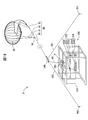
- FIG. 19 is a perspective view of a balloon mooring device according to the third embodiment.
- the balloon mooring device 31 includes a balloon 90, a mooring line 80, a mooring device 330, an engaging portion 340, a first stretching member 350, a second stretching member 351, and a first A holding member 360 and a second holding member 361 are provided.
- each of the balloon 90 and the mooring line 80 has the same configuration and function as the balloon 90 and the mooring line 80 of the first embodiment described above, detailed description thereof is omitted here.
- the mooring device 330 includes a housing 331, a rope guide device 332, a winding guide device 333, and a winding device 334.
- the housing 331 is a rectangular parallelepiped frame-shaped member formed of steel, and fixes each of the rope guide device 332, the winding guide device 333, and the winding device 334 to predetermined positions.
- the cable guide device 332 is a four-sided roller having two pairs of rollers arranged in a square shape, and when the main mooring line 85 is unwound from the winding device 334 as the balloon 90 rises and descends, and the main mooring line 85. , The main mooring line 85 is slidably guided when being wound around the winding device 334.
- the winding guide device 333 includes a guide roller 3330, a guide shaft 3331, and a guide motor 3332.
- the winding device 334 includes a winding drum 3340 disposed so as to extend parallel to the guide shaft 3331 and a winding motor 3341 that rotates the winding drum 3340 at a predetermined speed.
- the guide roller 3330 has a pair of rollers that are arranged so as to sandwich the main mooring line 85 and guide the main mooring line 85.
- the guide shaft 3331 is a cylindrical shaft member, and supports the guide roller 3330 so as to be movable.
- the guide motor 3332 is guided by the guide roller 3330 in synchronization with the rotation of the winding drum 3340 of the winding device 334.
- the guide roller 3330 is driven to move along 3331.
- the guide roller 3330 is driven to move along the guide shaft 3331 by a distance corresponding to the diameter of the main mooring line 85 while the winding drum 3340 makes one rotation, whereby the winding device 334 is moved. It becomes possible to wind up the main mooring line 85 in an orderly manner.
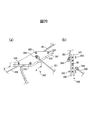
- FIG. 20 (a) is a partially enlarged view including the engaging portion 340
- FIG. 20 (b) is a cross-sectional view taken along the line AA ′ of FIG. 20 (a).
- the engaging portion 340 includes a first clamping member 341 and a second clamping member 342 that are a pair of flat metal plates, a fastening member 343, a first latching member 344, and a second latching member 345.
- the main mooring line 85 is engaged with the first suspension member 350 and the second suspension member 351.
- the 1st clamping member 341 and the 2nd clamping member 342 clamp the main mooring rope 85 between the surfaces which oppose.
- Each of the fastening members 343 is a bolt, and the main mooring line 85 is interposed between the first clamping member 341 and the second clamping member 342 by screwing the first latching member 344 and the second latching member 345 together. It is pinched.
- the first hooking member 344 is an annular hook that is screwed into the first clamping member 341, and hooks an annular portion formed at one end of the first tension member 350.
- the second hooking member 345 is an annular hook that is screwed into the second holding member 342, and hooks an annular portion formed at one end of the second stretching member 351.
- the engaging portion 340 is disposed at a position where the length of the main mooring line 85 between the engaging portion 340 and the winding device 334 is longer than the distance between the engaging portion 340 and the winding device 334. The That is, as indicated by an arrow A in FIG. 19, the engaging portion 340 is disposed at a position where the main mooring line 85 between the engaging portion 340 and the winding device 334 is loosened so that tension is not applied. .
- the first suspension member 350 and the second suspension member 351 are ropes formed of the same material as the mooring rope 80.
- One end of the first stretching member 350 is connected to the engaging portion 340 by being hooked by the first hooking member 344, and the other end of the first stretching member 350 is connected to the first holding member 360.
- one end of the second tension member 351 is connected to the engaging portion 340 by being hooked by the second hooking member 345, and the other end of the second tension member 351 is connected to the second holding member 361.
- the first holding member 360 and the second holding member 361 are piles placed on the ground, the first holding member 360 is connected to the first stretching member 350, and the second holding member 361 is the second stretching member. 351 is connected.
- the first holding member 360 and the second holding member 361 hold the main mooring line 85 via the engaging portion 340, the first stretching member 350, and the second stretching member 351.
- FIG. 21 is a diagram illustrating an operation when the balloon 90 is released in the balloon anchoring device 1, FIG. 21 (a) illustrates a first operation, and FIG. 21 (b) illustrates a second operation following the first operation.
- FIG. 21C shows a third operation following the second operation.
- the balloon 90 disposed on the upper surface of the mooring device 330 is in a state in which it can be released by being filled with helium gas from a gas cylinder (not shown).
- the winding device 334 is winding the main mooring line 85, and the balloon 90 does not rise and continues to be positioned on the upper surface of the mooring device 330.
- the winding device 334 unwinds the main mooring line 85, so that the balloon 90 is released.
- the posture of the balloon 90 becomes unstable. Therefore, the balloon 90 is not released, and the balloon 90 is released when the wind is relatively weak.
- the winding device 334 unwinds the main mooring line 85 so that the released balloon 90 is disposed at a desired height.
- the length of the main mooring rope 85 between the winding device 334 and the engaging part 340 is longer than the distance L between the winding device 334 and the engaging part 340.
- the engaging portion 340 is disposed on the main mooring line 85 between the balloon 90 and the winding device 334 so as to be long. More specifically, first, one end of the first tension member 350 is connected to the first holding member 341 via the first hooking member 344, and the other end of the first tension member 350 is connected to the first holding member 360. Connect to. Similarly, one end of the second tension member 351 is connected to the second holding member 342 via the second hooking member 345 and the other end of the second tension member 351 is connected to the second holding member 361.
- each of the first holding member 360 and the second holding member 361 is driven on the ground at a predetermined point.
- the first mooring line 85 is clamped by the first clamping member 341 and the second clamping member 342 by stretching both the first stretching member 350 and the second stretching member 351 so as not to loosen.
- the first clamping member 341 and the second clamping member 342 are screwed together with the fastening member 343 while the main mooring line 85 is clamped.
- the main mooring line 85 between the engaging part 340 and the winding device 334 is loosened by operating the winding device 334 and unwinding the main mooring line 85 to a desired length.
- the engaging portion is located at a position where the length of the main mooring line 85 between the winding device 334 and the engaging portion 340 is longer than the distance between the winding device 334 and the engaging portion 340.
- 340 is arranged and the first mooring line 85 is stretched between the first clamping member 341 and the second clamping member 342.
- the tension generated by the air balloon 90 receiving wind is applied to the first and second tension members 340 and 341 that stretch the main mooring line 85, and is not applied to the winding device 334.
- since the tension generated when the balloon 90 receives wind is not applied to the winding device 334, it is not necessary to increase the size of the winding drum 3340 and the winding motor 3341 of the winding device 334. .
- FIG. 22 is a perspective view of a balloon mooring device according to a first modification of the third embodiment.
- the first holding member 362 and the second holding member 363 are arranged instead of the first holding member 360 and the second holding member 361. Different from the mooring device 31. Therefore, the first holding member 362 and the second holding member 363 that are different from the balloon mooring device 31 will be described below.
- the constituent elements other than the first holding member 362 and the second holding member 363 of the balloon mooring device 32 have the same configuration and function as those of the balloon mooring device 31, and thus detailed description thereof is omitted here.
- the first holding member 362 is bonded to the first side 3311 that forms the upper surface of the housing 331, and the second holding member 363 is bonded to the second side 3312 that faces the first side 3311 and forms the upper surface of the housing 331. Is done. Since the first holding member 362 and the second holding member 363 are joined to the housing 331, the first stretching member 350 connected to the housing 331 via the first holding member 362 and the second holding member 363, and By connecting the engaging portion 340 to the second tension member 351, the main mooring line 85, the first tension member 350, and the second tension member 351 are engaged. Therefore, in the balloon mooring device 32, it is not necessary to place the first holding member and the second holding member on the ground.
- the balloon mooring device 31 according to the first modification of the third embodiment does not need to place the first holding member and the second holding member on the ground when the balloon 90 is released. This is different from the ball launching operation. In the balloon mooring device 32, it is not necessary to drive the first holding member and the second holding member on the ground. Therefore, in the balloon mooring device 32 according to the first modification, in a place where it is not easy to drive a pile such as sand. In addition, the balloon 90 can be released quickly and easily.
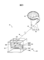
- FIG. 23 is a perspective view of a balloon mooring device according to a second modification of the third embodiment
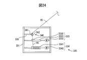
- FIG. 24 is a front view of the mooring device shown in FIG.
- the balloon mooring device 33 includes a balloon 90, a mooring line 80, a mooring device 335, and an engaging portion 340.
- the balloon 90, the mooring line 80, and the engaging portion 340 have the same configuration and function as the components having the same reference numerals of the balloon mooring device 31 described with reference to FIG. Is omitted.
- the mooring device 335 is different from the mooring device 330 described with reference to FIG. 19 in that the mooring device 335 includes a support arm portion 336 that supports the engaging portion 340.
- One end of the support arm portion 336 is connected to the steel material forming the housing 331 and the other end is joined to the first clamping member 341 of the engaging portion 340, thereby fixing the engaging portion 340 to the housing 331.
- the support arm 336 stretches the main mooring line 85 that is affected by the tension generated when the balloon 90 receives wind, like the first and second tension members 350 and 351 of the balloon anchoring devices 31 and 32. It has a function.
- the main mooring line 85 is released after the winding apparatus 334 unwinds the main mooring line 85 to release the balloon 90.
- the first clamping member 341 and the second clamping member 342 are screwed together by the fastening member 343 so as to clamp the.
- the tension generated by the strong wind is applied to the housing 331 via the support arm portion 336 that supports the engaging portion 340 that stretches the main mooring line 85, and is positioned below the engaging portion 340. It does not participate in the winding device 334.
- the engaging portion 340 is joined to the housing 331 via the support arm portion 336, and there is no possibility that the lift of the balloon 90 is reduced due to the weight of the engaging portion 340. Further, since the balloon mooring device 33 can prevent the tension from being applied to the winding device 334 by screwing the first clamping member 341 and the second clamping member 342 so as to clamp the main mooring line 85, the balloon mooring device 33 can be prevented. The balloon 90 can be released more quickly and easily than the devices 31 and 32.
- FIG. 25 is a perspective view of a balloon carrying device equipped with a balloon storage box according to a third modification of the third embodiment
- FIG. 26 is a perspective view of the balloon storage box mooring the balloon 90.
- the balloon transport device 370 includes a cargo vehicle 371 and a balloon storage box 372 mounted on the cargo vehicle 371.
- the cargo vehicle 371 includes an occupant room 3711 also called a cabin, and a loading platform 3712 disposed behind the occupant room 3711.
- the balloon storage box 372 is mounted on the loading platform 3712 and extends at right angles to the bottom surface 3720, the first side surface 3721, the second side surface 3722 facing the first side surface 3721, and the first side surface 3721 and the second side surface 3722. It has a third side surface 3723 and a fourth side surface 3724 opposite to the third side surface 3723.
- the balloon anchoring device 34 is stored inside the balloon storage box 372.
- the first holding member 364 and the second holding member 365 are arranged instead of the first holding member 360 and the second holding member 361. Different from the mooring device 31. Therefore, hereinafter, the first holding member 364 and the second holding member 365 that are different from the balloon mooring device 31 will be described.
- the constituent elements other than the first holding member 364 and the second holding member 365 of the balloon mooring device 34 have the same configuration and function as the balloon mooring device 31, and thus detailed description thereof is omitted here.
- the first holding member 364 and the second holding member 365 are joined to the bottom surface of the balloon storage box 372.
- the operation of releasing the balloon 90 is performed when the main mooring line 85 is stretched by the first tension member 350 and the second tension member 351. It is different from the ball releasing operation in the balloon anchoring device 31 that it is not necessary to place the first holding member and the second holding member on the ground. In the balloon mooring device 34, it is not necessary to drive the first holding member and the second holding member on the ground. Therefore, in the balloon mooring device 34, the balloon 90 can be quickly moved even in places where it is not easy to place a pile such as sand. And it can be easily released. Further, in the balloon carrier device 370, the balloon 90 can be released from the balloon storage box 372 mounted on the balloon carrier device 370, so that the balloon 90 can be easily carried and released.
- FIG. 27 is a perspective view of a balloon mooring ship equipped with a balloon mooring apparatus according to a fourth modification of the third embodiment.
- the balloon mooring ship 380 has a ship 381 and a balloon mooring device 35.
- the ship 381 has a hull 3810, a deck 3811 formed in front of the upper surface of the hull 3810, and a steering chamber 3812 formed in the center of the upper surface of the hull 3810, and is driven by an engine and a propulsion device (not shown). It is a running boat.
- the balloon mooring device 35 is mounted on the deck 3811 of the ship 381.
- the balloon mooring device 35 includes a balloon 90, a mooring line 80, a mooring device 330, an engaging portion 346, a tension member 352, and a holding member 366.
- the balloon 90, the mooring line 80, and the mooring device 330 have the same configuration and function as the components having the same reference numerals of the balloon mooring device 31 described with reference to FIG. Omitted.
- the engaging portion 346 is related to the fact that the two tension members, the first tension member 350 and the second tension member 351, are not connected but the tension member 352 that is a single tension member is connected. It is different from the joint part 340.
- the engaging portion 346 is configured such that the second hooking member 345 is not screwed into the second holding member 342, and one end of the stretching member 352 is screwed into the first holding member 341. It is hooked on the stop member 344 and connected to the engaging portion 346.
- the tension member 352 has one end connected to the engaging portion 346 and the other end connected to the holding member 366.
- the holding member 366 is connected to one end of the tension member 352 and has a weight that does not easily move due to tension generated when the balloon 90 receives wind, and is disposed in water.
- the holding member 366 is a ridge disposed on the bottom of the water.
- the holding member 366 is disposed in the water apart from the ship 381 so as not to give the ship 381 the influence of tension generated when the balloon 90 receives wind.
- the balloon 90 responds to the tension generated by receiving wind.
- the ship 381 may sway and the stability of the ship 381 may decrease.
- the holding member 366 since the holding member 366 is disposed in the water apart from the ship 381, there is a low possibility that the influence of the tension generated when the balloon 90 receives wind is exerted on the ship 381.
- the balloon mooring ship 380 by disposing the holding member 366 in the water apart from the ship 381, the possibility of giving the ship 381 the influence of the tension generated when the balloon 90 receives wind can be reduced. Further, since the balloon mooring ship 380 can use the anchor of the ship 381 as the holding member 366, it is possible to provide a balloon mooring ship that can stably moor the balloon 90 at a low cost.
- the engaging portion is disposed on the mooring line by screwing a clamping member that is a pair of metal plates with a fastening member. It is good also as another structure which can be engaged.
- FIG. 28 is a view showing another example of the engaging portion
- FIG. 28 (a) is a view showing a first example of the other engaging portion
- FIG. 28 (b) is a view showing another engaging portion. It is a figure which shows the 2nd example.
- the engagement portion 347 shown in FIG. 28A includes an arc portion 3470 formed by turning a part of the main mooring line 85, and a pressing member 3471 that holds a portion where the main mooring line 85 intersects.
- the engaging portion 348 shown in FIG. 28B is formed by weaving the engaging rope 3480 made of the same material as the main mooring line 85 into the main mooring line 85 with a splice. Since the engaging portions 347 and 348 are formed of the same material as the main mooring line, the engaging portions 347 and 348 can be wound together with the main mooring line 85 when the winding device 334 winds the mooring line. .
- a plurality of engaging portions 347 and 348 may be formed on the main mooring line 85, and by forming the plurality of engaging portions 347 and 348 on the main mooring line 85, the engaging portions 347 and 348 may be formed according to the height of the balloon 90.
- a joint can be prepared.
- the mooring lines are stretched by two stretch members, but the mooring lines are stretched by a single stretch member or three or more stretch members. May be.
- the mooring lines are stretched by a single stretch member, but the mooring lines may be stretched by two or more stretch members.
- the length of the main mooring line between the engaging portion and the winding device is between the engaging portion and the winding device 334. It is located at a position longer than the distance.
- the engaging portion may be arranged so that the length of the main mooring line between the engaging portion and the winding device is equal to the distance between the engaging portion and the winding device 334.
- the tension applied to the winding device can be reduced by applying a part of the tension to the tension member.
- the winding device is disposed in the housing, but the winding device may not be disposed in the housing. Further, in the balloon mooring devices 31 to 35, the winding device is arranged to wind and unwind the mooring cable via the rope guiding device and the winding guiding device. In addition, the mooring line may be wound and unwound without using the winding guide device.
- the balloon mooring device, the balloon storage box, the balloon carrying device, the balloon mooring ship, and the method for releasing the moored balloon according to the embodiment have the following modes.
- (1-1) a balloon mooring device for mooring a balloon; A bottom surface on which a balloon mooring device is disposed; A side surface whose lower side is arranged along the periphery of the bottom surface; An upper surface arranged to contact the upper side opposite to the lower side of the side surface; A side surface moving mechanism that moves at least a part of the side surface to increase the distance between the opposing side surfaces; An upper surface moving mechanism that rotates the side surface to open and close at least a part of the upper surface;
- FIG. 1 The balloon according to (1-2), wherein the side surface moving mechanism further moves the third side surface arranged along the third side extending from the first side vertex to the second side vertex.
- Storage box. (1-4) a balloon mooring device for mooring a balloon; A bottom surface on which a balloon mooring device is disposed; A side surface whose lower side is arranged along the periphery of the bottom surface; An upper surface arranged to contact the upper side opposite to the lower side of the side surface;
- a balloon storage box comprising: a side surface moving mechanism that moves at least a part of the side surface so as to increase a distance between the opposing side surfaces; and a top surface moving mechanism that rotates the side surface so as to open and close at least a part of the top surface , A vehicle with a balloon storage box,
- a balloon carrying device comprising: (1-5) The balloon carrying device according to (1-4), wherein the planar shape of the bottom surface is a rectangle and the width of the bottom surface is 2.5 m or less.
- a method of releasing a moored balloon comprising: (2-1) Balloons, A mooring line connected to a balloon, A winding device for unwinding and wind
- the support member has a support frame formed to be rotatable between a fall position and a standing position where the locking portion is supported and fallen, When the support frame is in the overturned position, the locking part is positioned in the first position, and when the support frame is in the standing position, the locking part is positioned in the second position.
- Balloon mooring device as described.
- the balloon mooring device according to (2-3) further including a rotating unit that is located at a base portion of the support frame and rotates the support frame between a fall position and a standing position.
- the balloon mooring device according to (2-3) further including a moving mechanism capable of rotating to the standing position while moving the support frame in the horizontal direction when the support frame is in the overturned position.
- (2-8) balloon mooring device A bottom surface on which a balloon mooring device is disposed; A side surface whose lower side is arranged along the periphery of the bottom surface; An upper surface arranged to contact the upper side opposite to the lower side of the side surface; A side surface moving mechanism that moves at least a part of the side surface to increase the distance between the opposing side surfaces; An upper surface moving mechanism that rotates to the side surface so as to open and close at least a part of the upper surface; Balloon mooring device With balloons, A mooring line connected to a balloon, A winding device for unwinding and winding the mooring line; A locking part for locking the mooring line unwound from the winding device; A support member that supports the locking portion so as to be movable between a first position and a second position that is higher than the first position; A balloon storage box characterized by comprising: (2-9) balloon mooring device; A bottom surface on which a balloon mooring device is disposed; A side surface whose lower side
- Balloon mooring device (3-3) The balloon anchoring device according to (3-1) or (3-2), wherein the tension member is a cable having one end connected to the engaging portion and the other end connected to the holding member. (3-4) The balloon mooring device according to (3-3), wherein the holding member is a pile placed on the ground. (3-5) further having a housing for storing the winding device; The balloon anchoring device according to (3-3), wherein the holding member is joined to the casing. (3-6) The engaging portion has a pair of clamping members that clamp the mooring line, and at least one of the pair of clamping members is connected to the tension member (3-1) to (3-5) The balloon mooring device according to any one of the above.
- a balloon mooring device comprising: (3-8) a balloon storage box for storing the balloon mooring device; A vehicle equipped with a balloon storage box, Balloon mooring device With balloons, A mooring line connected to a balloon; A winding device for unwinding and winding the mooring line; An engagement portion disposed on the mooring line between the balloon and the winding device; A tension member that has one end connected to the engagement portion and stretches the mooring line; A holding member to which the other end of the tension member is connected and joined to the balloon storage box; A balloon carrying device comprising: (3-9) Balloons, A mooring line connected to a balloon; A winding device for unwinding and winding
Landscapes
- Engineering & Computer Science (AREA)
- Mechanical Engineering (AREA)
- Aviation & Aerospace Engineering (AREA)
- Health & Medical Sciences (AREA)
- Public Health (AREA)
- Transportation (AREA)
- Toys (AREA)
Abstract
屋外で気球にガスが充填可能であり、且つアンカ等により地面に係留索を直接固定することなく、気球を係留可能な装置を提供する。 本発明に係る気球格納箱203は、気球90を係留する気球係留装置3と、気球係留装置3が配置された底面230と、下辺が底面230の周囲に沿って配置された側面240~244と、側面240~44の下辺と対向する上辺に接するように配置された上面250~254と、側面240~244の少なくとも一部を、対向する側面との間の距離を広げるように移動する側面移動機構260~263と、上面250~254の少なくとも一部を開閉させるように側面240~244に回転させる上面移動機構270~273とを有する。
Description
本発明は、気球格納箱、気球運搬装置、及び係留気球を放球する方法に関する。
災害等で基地局の動作が停止した場合、動作を停止した基地局がカバーしていたエリアでは、携帯電話等の携帯端末の通信ができなくなる通信障害が発生する。通信障害が発生した場合に、動作を停止した基地局を早急に回復して通信障害を解消することが求められる。しかしながら、基地局が倒壊した場合等、基地局の機能を早急に復旧することが困難な場合がある。
一方、気球と、気球を係留するために気球に接続された係留索とを有す係留気球が知られている。係留気球は、風力発電装置等の大型構造物を建設するときの上空の風速調査、風速及び気温等の鉛直分布の調査、及び災害時の被害状況の確認のための映像撮影等に使用されることが知られている。
特許文献1には、係留気球が記載されている。特許文献1に記載される係留気球は、気球と、気球に接続された係留索と、係留索を巻き取る気球係留装置(リール)と、リールを大地に固定するために使用される接地索及びアンカを有する。
本願発明者は、災害等で動作を停止した基地局を早急に復旧することが困難な場合に、基地局の機能を代替する中継局を気球に搭載して、動作を停止した基地局がカバーしていたエリアの通信障害を早急に回復することを見出した。中継局を搭載した気球を約100[m]の高度まで上昇させて係留することにより、半径3[km]以上のエリアをカバーする中継局を実現することができる。
中継局を搭載した気球は、通信障害の状況に応じて迅速に移動することを求められる場合があるので、中継局を搭載した気球を牽引車両に搭載して運搬することが考えられる。中継局を搭載した気球を牽引車両に搭載して運搬することにより、通信障害の状況が生じた基地局の近辺に中継局を搭載した気球を迅速に移動させることが可能になる。
しかしながら、気球の幅が2.5mよりも長い場合、道路を通行することができない場合があるため、気球にヘリウムガスを充填せずに、気球を折りたたむなどして、気球の幅が2.5m以下になるようにして運搬する必要がある。牽引車での気球の運搬後に気球にヘリウムガスを充填する場合には、気球ヘのヘリウムガスの充填作業は屋外で行われるので、ヘリウムガスを充填中の気球が風を受けることにより気球の姿勢が変動し、ヘリウムガスの充填作業に支障をきたすおそれがある。
さらに、特許文献1に記載されるように、アンカにより、気球に接続された係留索を大地に固定する場合、岩が多い地面、地盤が軟弱な地面及び舗装面等のアンカを容易に打ち込めない場所では、気球を地面に係留するために何らかの対策を講じる必要がある。
本発明は、これらの課題を解決するものであり、屋外で風の影響を受けないで気球にガスが充填可能であり、且つアンカ等により地面に係留索を直接固定することなく、気球を係留可能な装置を提供することを目的とする。
上記目的を実現するため、本発明に係る気球格納箱は、気球を係留する係留装置と、係留装置が配置された底面と、下辺が底面の周囲に沿って配置された側面と、側面の下辺と対向する上辺に接するように配置された上面と、側面の少なくとも一部を、対向する側面との間の距離を広げるように移動する側面移動機構と、上面の少なくとも一部を開閉させるように側面に回転させる上面移動機構とを有する。
また、本発明に係る気球格納箱では、底面は、方形であり、側面移動機構は、底面の第1辺に沿って配置された第1側面と、第1辺に対向する第2辺に沿って配置された第2側面とを移動することが好ましい。
また、本発明に係る気球格納箱では、側面移動機構は、底面の第1辺の頂点から第2辺の頂点に延伸する第3辺に沿って配置された第3側面を更に移動することが好ましい。
また、本発明に係る気球格納箱では、気球係留装置は、気球と、気球が接続された係留索と、係留索を巻き出し且つ巻き取る巻取装置と、巻取装置から巻き出された係留索を係止する係止部と、係止部を、第1位置と第1位置よりも高い位置である第2位置との間で移動可能に支持する支持部材と、を有することが好ましい。
また、本発明に係る気球格納箱では、支持部材は、係止部を支持し且つ長さが伸縮可能な伸縮脚を有し、伸縮脚の長さが第1の長さであるときに、係止部は第1位置に位置し、伸縮脚の長さが第1の長さより長い第2の長さであるときに、係止部は第2位置に位置することが好ましいことが好ましい。
また、本発明に係る気球格納箱では、支持部材は、係止部を支持し且つ転倒させた転倒位置と起立させた起立位置との間で回転可能に形成された支持架台を有し、支持架台が転倒位置に位置するときに、係止部は第1位置に位置し、支持架台が起立位置に位置するときに、係止部は第2位置に位置することが好ましい。
また、本発明に係る気球格納箱では、気球係留装置は、支持架台の基部に位置し、転倒位置と起立位置との間で回転させる回転部を更に有することが好ましい。
また、本発明に係る気球格納箱では、気球係留装置は、支持架台が転倒位置であるときに、支持架台を水平方向に移動しながら起立位置に回転可能な移動機構を更に有することが好ましい。
また、本発明に係る気球格納箱では、係止部は、係留索が通過する索通過口が形成されることが好ましい。
また、本発明に係る気球格納箱では、気球係留装置は、気球が係留されているときに、係止部を前記第2位置で固定する固定部材を更に有することが好ましい。
また、本発明に係る気球格納箱では、気球係留装置は、気球と、気球に接続された係留索と、係留索を巻き出し且つ巻き取る巻取装置と、気球と巻取装置との間で係留索に配置される係合部と、係合部に接続され、係留索を張架する張架部材と、を有することが好ましい。
また、本発明に係る気球格納箱では、気球が係留されているときの巻取装置と係合部との間の係留索の長さは、巻取装置と係合部との間の距離より長いことが好ましい。
また、本発明に係る気球格納箱では、張架部材は、一端が係合部に接続され、他端が保持部材に接続された索であることが好ましい。
また、本発明に係る気球格納箱では、張架部材の他端が接続され且つ気球格納箱に接合されることが好ましい。
また、本発明に係る気球格納箱では、気球係留装置は、巻取装置を収納する筐体を更に有し、保持部材は、筐体に接合されていることが好ましい。
また、本発明に係る気球格納箱では、係合部は、係留索を挟持する一対の挟持部材を有し、一対の挟持部材の少なくとも1つが張架部材に接続されることが好ましい。
また、本発明に係る気球格納箱では、気球係留装置は、気球と、気球に接続された係留索と、係留索を巻き出し且つ巻き取る巻取装置と、気球と巻取装置との間で係留索に配置される係合部と、巻取装置を収納する筐体であって、係合部を支持する支持部を有する筐体と、を有することが好ましい。
本発明に係る気球運搬装置では、気球を係留する気球係留装置と、気球係留装置が配置された底面と、下辺が底面の周囲に沿って配置された側面と、側面の下辺と対向する上辺に接するように配置された上面と、側面の少なくとも一部を、対向する側面との間の距離を広げるように移動する側面移動機構と上面の一辺を軸として上面を回転する上面回転機構を有する気球格納箱と、気球格納箱を搭載する車両とを有する。
また、本発明に係る係留気球を放球する方法は、気球を係留する気球係留装置が配置される底面と、下辺が底面の周囲に沿って配置され且つ少なくとも一部を、対向する側面との間の距離を広げるように移動可能な側面と、側面の下辺と対向する上辺に接するように配置され且つ一辺を軸として回転可能な上面と、を有する気球格納箱に格納されている係留気球を放球する方法であって、側面の移動可能な部分を、対向する側面との間の距離を広げるように移動し、気球格納箱の上面に開口部を形成するように、上面を回転して移動させ、係留気球にガスを充填し、ガスが充填された係留気球を上面の開口部から放球し、係留気球を放球した後に、側面の移動可能な部分を底面の周囲に沿う移動前の元の位置に移動させる、ことを含む。
本発明によれば、屋外で風に影響されることなく気球にガスを充填することができると共に、アンカ等により地面に係留索を直接固定することなく、気球を係留することが可能になった。
以下の図面を参照して、本発明に係る気球格納箱、気球運搬装置、及び係留気球を放球する方法について説明する。但し、本発明の技術的範囲はそれらの実施の形態に限定されず、特許請求の範囲に記載された発明との均等物に及ぶ点に留意されたい。
(第1実施形態に係る気球格納箱について)
第1実施形態に係る気球格納箱は、底面の周囲に沿って配置され且つ少なくとも一部が外側に向けて移動可能な側面を有する。第1実施形態に係る気球格納箱は、内部に格納された気球にヘリウムガスを充填するときに、側面の移動可能な部分を外側に移動させ、対向する側面との間の距離を広げることにより、ヘリウムガスが充填された気球を格納可能なように、気球格納箱の容積を増大させる。側面に囲まれた気球格納箱の内部で気球を充填させることにより、ヘリウムガスの充填中に風の影響で気球の姿勢が変動することを防止できる。
第1実施形態に係る気球格納箱は、底面の周囲に沿って配置され且つ少なくとも一部が外側に向けて移動可能な側面を有する。第1実施形態に係る気球格納箱は、内部に格納された気球にヘリウムガスを充填するときに、側面の移動可能な部分を外側に移動させ、対向する側面との間の距離を広げることにより、ヘリウムガスが充填された気球を格納可能なように、気球格納箱の容積を増大させる。側面に囲まれた気球格納箱の内部で気球を充填させることにより、ヘリウムガスの充填中に風の影響で気球の姿勢が変動することを防止できる。
以下、図1~8を参照して第1実施形態に係る気球格納箱、及び第1実施形態に係る気球格納箱を運搬する気球運搬装置について説明する。
図1は、気球格納箱を搭載した気球運搬装置の斜視図である。
図1は、気球格納箱を搭載した気球運搬装置の斜視図である。
気球運搬装置1は、貨物車両202と、貨物車両202に搭載された気球格納箱203とを有する。貨物車両202は、キャビンとも称される乗員室221と、乗員室221の後方に配置される荷台222とを有する。貨物車両202の幅は、道路を通行することができるように、2.5メートル以下である。
図2(a)は図1のA-A´線に沿う断面図であり、図2(b)は図1のB-B´線に沿う断面図である。
気球格納箱203は、長方形の底面230と、下辺が底面230の周囲に沿って配置された側面240と、側面の上辺に接するように配置された上面250とを有する。気球格納箱203は、側面の一部を底面230の周囲から外周に向けて移動する側面移動機構260と、上面250の一辺を軸として上面250を回転する上面移動機構270とを有する。底面230の表面には気球係留装置3が固定される。気球係留装置3は、気球90と、係留装置95と、係留装置95の内部に配置される不図示の巻取装置と係留索を介して接続される気球90とを有する。図2に示す例では、気球90は、係留装置95の上面にヘリウムガスがほとんど充填されていない状態で配置される。
気球格納箱203の幅は、貨物車両202の幅以下である。すなわち、気球格納箱203の幅は、2.5メートル以下である。気球格納箱203の幅を2.5メートル以下にすることにより、貨物車両202は、気球格納箱203を搭載した状態で、道路を通行することができる。
側面240は、乗員室221から後方に向かって延伸する底面230の第1辺から上方に延伸する方形の第1側面241と、底面230の第1辺と対向する第2辺から上方に延伸する方形の第2側面242とを有する。側面240は、底面230の第1辺の後方の頂点から第2辺の後方の頂点に延伸する第3辺から上方に延伸する方形の第3側面243と、底面230の第1辺の前方の頂点から第2辺の前方の頂点に延伸する第4辺から上方に延伸する方形の第4側面244とを更に有する。
上面250は、第1側面241の上辺から第1側面241に垂直の方向に延伸する第1上面251と、第2側面242の上辺から第2側面242に垂直の方向に延伸する第2上面252と、第3側面243の上辺から第3側面243に垂直の方向に延伸する第3上面253とを有する。第1上面251及び第2上面252は、互いの先端部が重なるように配置され、第3上面253は、第1上面251及び第2上面252の下方に位置するよう配置される。
側面移動機構260は、第1側面241を移動する第1側面移動機構261と、第2側面242を移動する第2側面移動機構262と、第3側面243を移動する第3側面移動機構263とを有する。
図3は、第1側面移動機構261の斜視図である。図3は第1側面移動機構261の構成の一例を示すものであり、第1側面移動機構261の構成は図3に示す構成に限定されるものではない。第2側面移動機構262及び第3側面移動機構263のそれぞれは、第1側面移動機構261と同様の構成及び機能を有するので、第2側面移動機構262及び第3側面移動機構263の詳細な説明は省略する。
第1側面移動機構261は、第1腕部2611~第3腕部2613と、ラック2614と、ピニオン2615と、駆動部2616とを有する。第1腕部2611~第3腕部2613及びラック2614のそれぞれは、一端が第1側面241に接合される。ピニオン2615は、ラック2614に嵌合され、駆動部2616の回転に応じて、ピニオン2615に接合された第1側面241を移動する。駆動部2616は、不図示の電源から電源供給されるモータ及び減速機を有し、第1側面241を移動することを示す第1側面移動指示を受けると、回転を開始し、所定の時間が経過した後に回転を停止する。第1側面移動機構261のラック2614、ピニオン2615及び駆動部2616は、リニアヘッドとも称される一体型の直線移動機構としてもよい。
第1側面移動機構261は、第1側面41を、前方から後方に向かって延伸する底面230の第1辺から外側に向けて移動する。第2側面移動機構262は、第1側面241を底面230の第1辺と対向する第2辺から外側に向けて移動する。第2側面移動機構262は、第1側面241を底面230の第1辺と対向する第2辺から外側に向けて移動する。第3側面移動機構263は、底面230の第1辺の後方の頂点から第2辺の後方の頂点に延伸する第3辺から外側に向けて移動する。
上面移動機構270は、第1上面251を回転させる第1上面移動機構271と、第2上面252を回転させる第2上面移動機構272と、第3上面253を回転させる第3上面移動機構273とを有する。
図4は第1上面移動機構271の動作を説明する側面図であり、図4(a)は第1上面移動機構271が第1上面251を回転する前の状態を示す図であり、図4(b)は第1上面移動機構271が第1上面251を回転した後の状態を示す図である。図4は第1上面移動機構271の構成の一例を示すものであり、第1上面移動機構271の構成は図4に示す構成に限定されるものではない。第2上面移動機構272及び第3上面移動機構273のそれぞれは、第1上面移動機構271と同様の構成及び機能を有するので、第2上面移動機構272及び第3上面移動機構273の詳細な説明は省略する。
第1上面移動機構271は、回転部2711と、駆動部2712とを有する。回転部2711は、第1側面241と、第1上面251とを接続する。駆動部2712は、コボレーンとも称される電導回転機構であり、不図示の電源から電源供給されるモータ及び減速機で形成される。駆動部2712が回転部2711を回転することにより、第1側面241に接続された第1上面251が回転して、水平方向に延伸するように配置されていた第1上面251は、鉛直方向に延伸するように移動する。
底面230に固定された係留装置95の内部には、一例では電動のウインチの巻取装置が配置され、ヘリウムガスが十分に充填されて上昇可能になった気球90を係留する。係留索の他端に接続される巻取装置から主係留索が巻き出されるとき、ヘリウムガスが充填された気球90は巻取装置からの係留索の巻出量に応じて空中に上昇し、巻取装置によって主係留索が巻き取られるとき、気球90は巻取量に応じて空中から下降する。係留装置95は、気球格納箱203の底面230に固定されているので、アンカ等により地面に係留索を直接固定する必要はない。
気球90は、合成繊維等の堅固、軽量且つ風を通さない材料で形成される外袋と、ヘリウムガスが充填されるヘリウム収納袋とを有する。気球90は、ヘリウム収納袋及び空気収納袋と外袋との二重構造となっているので、外袋は、ガスバリア性を有する材料で形成される必要はない。尚、気球90は本構成の一例を示すものであり、ヘリウム収納袋だけで構成される気球でも可能であり、その構成に限定されるものではない。
図5は、気球90を放球中の気球運搬装置1の斜視図である。
気球90は、第1係留索81~第3係留索83と、第1係留索81~第3係留索83に結節点84を介して接続される主係留索85とに形成される係留索80により、係留装置95の内部に配置される巻取装置によって係留される。気球運搬装置1では、気球90を放球する前に、第1側面移動機構261~第3側面移動機構263のそれぞれが第1側面241~第3側面243のそれぞれを移動する。また、気球90を放球する前に、第1上面移動機構271~第3上面移動機構273のそれぞれが第1上面251~第3上面253のそれぞれを回転して、第1側面241~第3側面243に対向する位置に移動する。第1側面241~第3側面243を底面230の周囲から外側に向けて移動して対向する側面との間の距離を広げることにより、気球格納箱203の容積が大きくなり、ヘリウムガスが充填された気球90を収納することができる容積を気球格納箱203が確保可能になる。気球格納箱203は、第1上面251~第3上面253を第1側面241~第3側面243に対向する位置に回転することにより、気球90を係留する係留装置95が配置される底面230の上方に、気球90が放球可能な開口部を確保することができる。
図6~8は、気球運搬装置1における気球90を放球するときの動作を示す概略図である。図6は右側方向からの気球運搬装置1の断面図であり、図7は後方からの気球運搬装置1の断面図であり、図7は後方からの気球運搬装置1の平面図である。図6(a)、7(a)及び8(a)は第1の状態を示し、図6(b)、7(b)及び8(b)は第1の状態に続く第2の状態を示す。以下同様に、図6(c)~6(h)、7(c)~7(h)及び8(c)~8(h)のそれぞれは前の状態に続く状態を示し、図6(i)、7(i)及び8(i)は第8の状態に続く第9の状態を示す。
まず、気球運搬装置1は、所望の係留点に停車される(図6(a)、7(a)及び8(a)を参照)。ここでは、貨物車両202により運搬されるために気球格納箱203の側面240は、底面230の周囲に沿って配置され、上面250は底面230に対向する位置に配置されている。気球格納箱203に格納されている気球90はヘリウムガスが充填されていない。なお、気球90を迅速に放球するために、気球90は、気球格納箱203に格納可能な大きさになる程度にヘリウムガスが充填されていてもよい。
次いで、側面移動機構260は、側面240を底面230の周囲から外側に向けて移動して、対向する側面との間の距離を広げる(図6(b)、7(b)及び8(b)を参照)。第1側面移動機構261は第1側面241を底面230の端部から外側に移動し、第2側面移動機構262は第2側面242を底面230の端部から外側に移動し、第3側面移動機構263は第3側面243を底面230の端部から外側に移動する。第1側面移動機構261~第3側面移動機構263のそれぞれが第1側面241~第3側面243のそれぞれを底面230の周囲から外側に向けて移動することにより、気球格納箱203の容積は第1側面241~第3側面243が移動する前よりも大きくなる。気球格納箱203の容積が気球の大きさに応じて大きくなることにより、気球90は、気球格納箱203の内部でヘリウムガスを充填することが可能になる。
次いで、上面移動機構270は、上面250の一辺を軸として上面250を回転して上面250が側面240に対向する位置となるように移動する(図6(c)、7(c)及び8(c)を参照)。第1上面移動機構271は第1側面241と接する第1上面251の辺を軸として第1上面251を回転し、第2上面移動機構272は第2側面242と接する第2上面252の辺を軸として第2上面252を回転する。第3上面移動機構273は、第3側面243と接する第3上面253の辺を軸として第3上面253を回転する。第1上面移動機構271~第3上面移動機構273のそれぞれは、第1上面251~第3上面253のそれぞれを回転して、第1上面251~第3上面253のそれぞれを第1側面241~第3側面243のそれぞれと対向する位置に移動する。第1上面251~第3上面253のそれぞれを回転することにより、気球格納箱203の底面230の上方には開口部が形成される。気球格納箱203の底面230の上方には開口部が形成されることにより、気球格納箱203の内部でヘリウムガスが充填された気球90は、気球格納箱203の外部に移動されることなく、気球格納箱203の内部から放球されることが可能になる。
次いで、気球90は、不図示のガス貯蔵容器に貯蔵されたヘリウムガスが充填される(図6(d)、7(d)及び8(d)を参照)。ヘリウムガスが充填された気球90は、係留装置95の内部に配置される巻取装置から係留索が巻き出されるまで気球格納箱203の内部で保持される。
次いで、気球90は、放球され、上昇する(図6(e)、7(e)及び8(e)を参照)。気球係留装置3が係留装置95の内部に配置される巻取装置から主係留索85が巻き出すに従って、気球90は上昇する。気球90の高さが所望の高さになると、係留装置95の内部に配置される巻取装置の巻き出しを終了する。
次いで、側面移動機構260は、底面230の周囲の外側に配置された側面240を底面230の周囲に向けて移動する(図6(f)、7(f)及び8(f)を参照)。第1側面移動機構261は第1側面241を底面230の端部に移動し、第2側面移動機構262は第2側面242を底面230の端部に移動し、第3側面移動機構263は第3側面243を底面230の端部に移動する。側面240を底面230の周囲に位置させることにより、側面が元の位置に戻り、気球格納箱の内部に側面からの風を受けることがない。また、気球格納箱の内部に側面から人々が侵入することを防止できる。気球90が放球されている間、側面240は、底面230の周囲に沿って配置される(図6(g)、7(g)及び8(g)を参照)。
次いで、放球されている気球90を収容するために、側面移動機構260は、側面240を底面230の周囲から外側に向けて移動する(図6(h)、7(h)及び8(h)を参照)。第1側面移動機構261は第1側面241を底面230の端部から外側に移動し、第2側面移動機構262は第2側面242を底面230の端部から外側に移動し、第3側面移動機構263は第3側面243を底面230の端部から外側に移動する。
そして、気球90は、降下して、収容される(図6(i)、7(i)及び8(i)を参照)。係留装置95の内部に配置される巻取装置が主係留索85を巻き取るに従って、気球90は降下する。気球90を格納位置まで降下させると、係留装置95の内部に配置される巻取装置は主係留索85の巻き取りを終了する。
第1実施形態に係る気球格納箱203は、側面240を底面230の周囲から外側に向けて移動する側面移動機構260を有するので、気球格納箱203の内部で気球90にヘリウムガスを充填することが可能になる。気球格納箱203の内部で気球90にヘリウムガスを充填することができるので、ヘリウムガスを充填中の気球90は風の影響を抑制することができ、気球90の姿勢が変動することによりヘリウムガスの充填作業に支障をきたすおそれは低い。また、気球90は、底面230に固定された係留装置95によって係留されるので、アンカ等により地面に係留索を直接固定する必要はない。
また、第1実施形態に係る気球格納箱203は、上面250の一辺を軸として上面250を回転して上面250が側面240に対向する位置となるように移動にする上面移動機構270を有するので、気球格納箱203の底面230の上方には開口部が形成される。気球格納箱203の底面230の上方には開口部が形成されることにより、気球格納箱203の内部でヘリウムガスが充填された気球90は、気球格納箱203の外部に移動することなく、気球90を気球格納箱203の内部から放球することが可能になる。
また、第1実施形態に係る気球格納箱203では、気球90の放球中は、側面240を元の位置に戻すことで、気球格納箱の内部に側面からの風を受けることがない。また、気球格納箱の内部に側面から人々が侵入することを防止できる。
また、第1実施形態に係る気球運搬装置1は、気球格納箱203と、気球格納箱203を搭載する貨物車両202とを有するので、気球運搬装置1は、気球90を所望の場所に運搬可能であると共に、運搬先で迅速に気球90を放球することができる。
また、第1実施形態に係る気球運搬装置1では、貨物車両202の幅及び気球格納箱203の幅が2.5メートル以下であるので、貨物車両202は、気球格納箱203を搭載した状態で、道路を通行することができる。
第1実施形態に係る気球格納箱203は、第1側面241、第2側面242及び第3側面243の3つの側面が移動可能であるが、1つ又は2つの側面が移動可能な構造としてもよく、4つの側面全てを移動可能にしてもよい。例えば、気球格納箱203の長さが、ヘリウムガスが充填された気球90の直径よりも長い場合、第3側面243は移動可能にしなくてもよい。また、また、第1側面241又は第2側面242の何れかが移動可能な構造にしてもよい。気球格納箱203の底面230は方形であるが、円形、三角形等の他の形状としてもよい。また、気球格納箱203は、貨物車両202に搭載されていなくてもよい。
また、第1実施形態に係る気球格納箱203では、第1上面251、第2上面252及び第3上面253の3つの上面が回転可能であるが、1つ又は2つの側面が回転可能な構造としてもよく、上面250を回転可能な構造にしなくてもよい。
また、第1実施形態に係る気球格納箱203では、側面240を底面230の周囲から外側に移動したとき、第1側面241と第3側面243との間、第1側面241と第4側面244との間、第2側面242と第3側面243との間、第2側面242と第4側面244との間に空隙が形成される。しかしながら、第1側面241~第4側面244の間に形成される空隙から風が気球格納箱203の内部に侵入することを防止するために、気球格納箱は、第1側面241~第4側面244の間に形成される空隙に配置可能な空隙用側面を更に有してもよい。気球格納箱が第1側面241~第4側面244の間に形成される空隙に配置可能な空隙用側面を有することにより、気球格納箱203の内部に人が侵入することを防止することが可能になる。
以上、図1~8を参照して第1実施形態に係る気球格納箱、及び第1実施形態に係る気球格納箱を運搬する気球運搬装置について説明した。次いで、図9~18を参照して、第2実施形態に係る気球係留装置及びその変形例、並びに第2実施形態に係る気球係留装置を収納する気球収納箱について説明する。
図1~8を参照して説明したように、気球係留装置の周囲に気球格納箱203の側面240のような防護壁を設置すると、気球が風を受けて気球係留装置の直上の位置から移動した場合に、主係留索85が防護壁の上面に接触するおそれがある。主係留索85の防護壁への接触が繰り返されると、主係留索85が擦れて徐々に摩耗し、切断するおそれがある。また、気球係留装置の周囲には、防護壁の他にも種々の障害物が配置されていることがあり、これらの障害物と係留索とが接触するおそれもある。
図9~18を参照して説明される気球係留装置は、この課題を解決するものであり、気球係留装置が係留索を介して気球を係留するときに、気球係留装置の周囲に配置された障害物に係留索が接触するおそれが低い気球係留装置を提供することを目的とする。
図1~8を参照して説明したように、本願発明者は、気球が収納可能な気球収納箱を搭載した気球運搬装置で気球を通信障害が生じた基地局の近傍まで運搬し、気球収納箱の上面を開放して、上面が開放された気球収納箱から気球を放球することを見出した。気球を気球運搬装置で運搬し、気球運搬装置で運搬された気球収納箱から気球を放球することにより、気球を早急に容易に放球することが可能になる。
図9(a)は気球運搬装置に搭載された気球格納箱から気球を放球する状態を示す概略断面図であり、図9(b)は放球された気球が風を受けた第1の状態を示す概略断面図であり、図9(c)は放球された気球が風を受けた第2の状態を示す概略断面図である。
気球運搬装置901は、タイヤ9020及び荷台9021を備える貨物車両902と、貨物車両902に搭載され側面9031を備える気球格納箱903とを有する。気球格納箱903には巻取装置等を含む係留装置910と、係留装置910に係留索980を介して接続された気球990が搭載される。気球運搬装置901で運搬された気球990を係留するとき、上面が開放された気球格納箱903から気球990が放球される。気球990は、強風下では放球できないため、気球990は、略無風のとき又は微風下で放球される。放球された気球990は、放球された直後は、係留装置910の直上に位置している。その後、風速が増加するに従って、気球990は係留装置910の直上の位置から移動し、気球990と係留装置910とを接続する係留索980と鉛直方向との間の係留索傾斜角θiは大きくなる。そして、さらに風速が増加すると、係留索980が側面9031に接触するおそれがある。係留索980が側面9031に接触することを防止するために、係留索980が側面9031に接触することを防止するために、側面を倒すこと、及び側面の高さを低くすることが考えられる。
図9(d)は気球格納箱の側面を倒した状態を示す概略断面図であり、図9(e)は気球格納箱の側面の高さを低くした状態を示す概略断面図である。
図9(d)に示す例では、気球運搬装置911に搭載された気球格納箱913は、側面9032を外側に回転させることによって、側面9032を倒している。一方、図9(e)に示す例では、気球運搬装置921に搭載された気球格納箱923は、側面9033を折曲することによって、側面9033の高さを低くしている。気球格納箱913の側面9032を倒す、又は気球格納箱923の側面9033の高さを低くすることにより、気球990が強風を受けて係留索傾斜角θiが最大となった場合でも係留索980が側面9031に接触することを防止することができる。
しかしながら、側面9032を外側に回転させる場合には、側面9032を倒すための領域を気球運搬装置911の周囲に確保する必要がある。一方、側面9033を折曲して側面9033の高さを低くする場合、側面9033を折曲する機構が必要になるため気球格納箱923の構造が複雑になる。また、側面9032を外側に回転させる場合及び側面9033の高さを低くする場合の何れの場合も、公衆が係留装置910に接近して公衆が係留索に接触する等の不測の事態が生じるおそれがある。さらに、これらの場合では、気球係留装置の巻き取り装置等が視認可能になるため、気球係留装置の美感が低下するという問題がある。
そこで、第2実施形態に係る気球係留装置は、気球の放球までは、気球係留装置が気球を係留する位置を低くし、気球を係留する間は、気球係留装置が気球を係留する位置を高くする。すなわち、第2実施形態に係る気球係留装置は、巻取装置から巻き出された係留索を係止する係止部と、第1位置と第1位置よりも高い位置である第2位置との間で係止部を移動可能に支持する支持部材とを有する。気球に気体を充填して放球するときは、気球係留装置は、気球の充填作業が容易な第1位置で気球を係留する。気球の係留中、第2実施形態に係る気球係留装置は、係止部を第1位置よりも高い位置である第2位置で気球を係留する。第2実施形態に係る気球係留装置は、気球の係留中に気球をより高い位置で係留するので、気球を係留中に、係留索が側面に接触するおそれが低くなる。
図10は、気球格納箱を搭載した第2実施形態に係る気球運搬装置の斜視図である。
気球運搬装置2は、貨物車両202と、貨物車両202に搭載された気球格納箱203とを有する。貨物車両202及び気球格納箱203は、図1及び2等を参照して説明した同一符号を有する貨物車両及び気球格納箱と同一の構成及び機能を有するので、ここでは、詳細な説明を省略する。
図11(a)は図10のA-A´線に沿う断面図であり、図11(b)は図10のB-B´線に沿う断面図である。
(第1実施形態で説明済なので削除しました。)
気球格納箱203の内部には、支持架台10と、巻取装置17と、巻取装置17に主係留索85を含む係留索80を介して接続される気球90を有する気球係留装置4が配置される。支持架台10及び巻取装置17は、気球格納箱203の底面230に固定され、気球90は、ヘリウムガスがほとんど充填されていない状態で支持架台10の上面に搭載される。
図12(a)は気球90が放球された直後の気球係留装置4の斜視図であり、図12(b)は気球90を係留中の気球係留装置4の斜視図である。
支持架台10は、底枠部11と、上枠部12と、第1伸縮脚131~第4伸縮脚134と、第1固定部材141~第4固定部材144と、索案内装置15と、ローラ16とを有する。
底枠部11及び上枠部12のそれぞれは、鋼材で形成された枠状部材であり、底枠部11は不図示の締結部材により気球格納箱203の底面230に締結され、上枠部12は対向する辺から延伸する索案内装置支持部121及び122によって索案内装置15を支持する。
第1伸縮脚131~第4伸縮脚134のそれぞれは、第1の長さL1と第1の長さL1よりも長い第2の長さL2との間で伸縮可能な鋼材で形成された部材で、一端が底枠部11の角に接合され、他端が上枠部12の角に接合される。第1伸縮脚131~第4伸縮脚134の長さは、気球運搬装置2により移動して気球90にヘリウムが充填されて気球90が放球されるまでの間、第1の長さL1とする。また、第1伸縮脚131~第4伸縮脚134の長さは、気球90を係留している間、第2の長さL2とする。第1固定部材141~第4固定部材144のそれぞれは、気球90を係留している間、第1伸縮脚131~第4伸縮脚134を第2の長さL2に固定する。第2の長さL2は、気球格納箱203の側面240の高さと、索案内装置15と側面240との間の距離によって規定される。例えば、係留中の気球90の最大傾斜角が45度である場合、第2の長さL2は、索案内装置15の高さに相当する第2の長さL2と側面240の高さとの差が索案内装置15と側面240との間の距離以上の長さになるように規定される。
索案内装置15は、方形に配置された2対のローラを有する四面ローラであり、四面ローラの内側に索通過口150が形成される。索案内装置15は、気球90の上昇及び下降に伴って主係留索85が巻取装置17から巻き出されるとき及び主係留索85が巻取装置17に巻き取られるときに、索通過口150を通る主係留索85を摺動自在に案内する。索案内装置15は、索通過口150で規定される移動範囲内で移動する主係留索85を介して気球90を索通過口150で係止する係止部として機能する。
ローラ16は、底枠部11に固定された回転可能な筒状部材であり、巻取装置17から水平方向に延伸してきた主係留索85を索通過口150が位置する鉛直方向に屈折させる。巻取装置17は、主係留索85を巻き取る巻取ドラム(図示せず)と、巻取ドラムを所定の速度で回転させる巻取モータ(図示せず)とを有する。巻取モータは、主係留索85を巻き出すときに巻取ドラムを巻き出し方向に回転させ、主係留索85を巻き取るときに巻取ドラムを巻き出し方向と反対方向の巻き取り方向に巻取ドラムを回転させる。巻取装置17は、気球90が係留されている間は、気球90の位置を一定にするために、主係留索85の長さを一定の長さに固定する。
気球係留装置4は、気球90を係留中に、第1伸縮脚131~第4伸縮脚134の長さを気球90の放球前よりも長くすることにより、気球90を係止する係止部である索案内装置15の高さが高くなるので、係留索が側面240に接触するおそれが低くなる。
~
(第1実施形態で説明済なので削除しました。)
図13は、気球90を係留中の気球運搬装置2の斜視図である。図13では、説明を容易にするために、第1側面241~第3側面243は底面230の周囲から外側に向けて移動されているが、気球90を係留しているとき、第1側面241~第3側面243は底面230の周囲に位置していることが好ましい。
~
(第1実施形態で説明済なので削除しました。)
気球運搬装置2では、気球90が放球された後、支持架台10の第1伸縮脚131~第4伸縮脚134のそれぞれを第1の長さL1から第1の長さL1よりも長い第2の長さL2に伸ばした状態で、第1固定部材141~第4固定部材144で固定する。気球90を係留する間、支持架台10の第1伸縮脚131~第4伸縮脚134のそれぞれの長さは第2の長さL2で固定されているので、気球90が風により移動して係留索傾斜角が大きくなっても主係留索85が側面240に接触するおそれは低い。
図14~16は、気球運搬装置2における気球90を放球するときの動作を示す概略図である。図14は右側方向からの気球運搬装置2の断面図であり、図15は後方からの気球運搬装置2の断面図であり、図16は後方からの気球運搬装置2の平面図である。図14(a)、15(a)及び16(a)は第1の状態を示し、図14(b)、15(b)及び16(b)は第1の状態に続く第2の状態を示す。以下同様に、図14(c)~14(g)、15(c)~15(g)及び16(c)~16(g)のそれぞれは前の状態に続く状態を示し、図14(h)、15(h)及び16(h)は第7の状態に続く第8の状態を示す。
図14(a)、15(a)及び16(a)を参照して説明される第1の状態から図14(d)、15(d)及び16(d)を参照して説明される第4の状態までは、第1実施形態に係る気球運搬装置1の状態と同一なのでここでは詳細な説明は省略する。
~
(第1実施形態で説明済なので削除しました。)
第5の状態において、気球90は、放球され、上昇する(図14(e)、15(e)及び16(e)を参照)。気球係留装置4が巻取装置17から主係留索85が巻き出すに従って、気球90は上昇する。気球90の高さが所望の高さになると、気球係留装置4は主係留索85の巻き出しを終了する。
次いで、側面移動機構260は、底面230の周囲の外側に配置された側面240を底面230の周囲に向けて移動する(図14(f)、15(f)及び16(f)を参照)。第1側面移動機構261は第1側面241を底面230の端部に移動し、第2側面移動機構262は第2側面242を底面230の端部に移動し、第3側面移動機構263は第3側面243を底面230の端部に移動する。側面240を底面230の周囲に位置させることにより、側面が元の位置に戻り、気球格納箱の内部に側面から人々が侵入することを防止できる。気球90が放球されている間、側面240は、底面230の周囲に沿って配置される(図14(g)、15(g)及び16(g)を参照)。このときの支持架台10の第1伸縮脚131~第4伸縮脚134の長さは、第1の長さL1である。
そして、支持架台10の第1伸縮脚131~第4伸縮脚134のそれぞれを第1の長さL1から第1の長さL1よりも長い第2の長さL2に伸ばして、第1固定部材141~第4固定部材144で固定する(図14(h)、15(h)及び16(h)を参照)。
図17は第1変形例に係る気球係留装置を示す図であり、図17(a)は気球90が放球された直後の第1変形例に係る気球係留装置の斜視図であり、図17(b)は気球90を係留中の第1変形例に係る気球係留装置の斜視図である。
第1変形例に係る気球係留装置5は、固定部材24が配置されることが気球係留装置4と相違する。また、気球係留装置5は、支持架台10の代わりに、回転部21を有し且つ第1伸縮脚131~第4伸縮脚134の代わりに第1脚231~第4脚234が配置された支持架台20を有することが気球係留装置4と相違する。そこで、以下では気球係留装置4と相違する回転部21、第1脚231~第4脚234及び固定部材24について説明する。なお、気球係留装置5の回転部21、第1脚231~第4脚234及び固定部材24以外の構成素子は、気球係留装置4と同様な構成及び機能を有するので、ここでは詳細な説明は省略する。
回転部21は、支持架台20の基部に位置し、底枠部11の一辺に接合された軸210と、軸210の両端に配置され軸を回転可能に気球格納箱203の底面230に固定する軸受部211とを有し、支持架台20を気球格納箱203の底面230に回転可能に支持する。第1脚231~第4脚234のそれぞれは、鋼材で形成された棒状部材であり、一端が底枠部11に接続され、他端が上枠部12に接続される。固定部材24は、一端が気球格納箱203の底面230に回転可能に固定され、他端が気球格納箱203の底面230に不図示の締結部材で締結可能な円弧状の部材である。
支持架台20は、図17(a)に示すように第1脚231及び第2脚232が気球格納箱203の底面230に接する転倒位置と、図17(b)に示すよう底枠部11が気球格納箱203の底面230に接する起立位置との間で回転可能である。支持架台20が図17(b)に示す起立位置のとき、固定部材24は、底枠部11の軸210が接合された辺に対向する辺を気球格納箱203の底面230に固定する。固定部材24が底枠部11の一辺を固定することにより、支持架台20が起立位置では、支持架台20は回転部21によって回転されることはない。
支持架台20は、気球運搬装置2により移動して気球90にヘリウムが充填されて気球90が放球されるまでの間、転倒位置にされる。また、支持架台20は、気球90を係留している間、起立位置にされる。支持架台20が転倒位置のとき、気球格納箱203の底面230から主係留索85が通過する索通過口150の上部までの高さは第1の長さL1になる。また、支持架台20が起立位置のとき、気球格納箱203の底面230から索案内装置15の上面までの高さは第1の長さL1よりも長い第2の長さL2になる。
図18は第2変形例に係る気球係留装置を示す図であり、図18(a)は気球90が放球された直後の第1変形例に係る気球係留装置の斜視図であり、図18(b)は気球90を係留中の第2変形例に係る気球係留装置の斜視図である。
第2変形例に係る気球係留装置6は、回転部を有さず且つ固定部材24の代わりに及び固定部材324を有することが第1変形例に係る気球係留装置5と相違する。また、支持架台20の代わりに、第1レール321、第2レール322及び第1車輪36~第4車輪39を有する支持架台30を有することが気球係留装置5と相違する。そこで、以下では気球係留装置5と相違する固定部材324、第1レール321、第2レール322及び第1車輪36~第4車輪39について説明する。なお、気球係留装置6の固定部材324、第1レール321、第2レール322及び第1車輪36~第4車輪39以外の構成素子は、気球係留装置5と同様な構成及び機能を有するので、ここでは詳細な説明は省略する。
第1レール321及び第2レール322は凹形状の断面を有し、第1脚231と第2脚232との間の長さと略同一の長さ離隔して平行に配置される。第1車輪36~第4車輪39のそれぞれは、第1レール321及び第2レール322の凹部に配置可能な一対の車輪と、支持架台30に接合され、一対の車輪を回転可能に支持する軸とを有する。第1車輪36及び第2車輪37は、支持架台30が図18(a)に示す転倒位置のとき、第1レール321及び第2レール322の凹部に配置される。また、第3車輪38及び第4車輪39は、支持架台30が図18(b)に示す起立位置のとき、第1レール321及び第2レール322の凹部に配置される。固定部材24は、両端が気球格納箱203の底面230に不図示の締結部材で締結可能な円弧状の部材である。固定部材24は、支持架台30が起立位置のときに、底枠部11の一辺を気球格納箱203の底面230に固定する。第1レール321、第2レール322及び第1車輪36~第4車輪39は、底枠部11、上板部及び第1脚231~第4脚234とは、支持架台30が転倒位置であるときに、支持架台30を水平方向に移動しながら起立位置に回転可能な移動機構を形成する。
支持架台30は、不図示の作業者が第1車輪36~第4車輪39を第1レール321及び第2レール322上で滑走させると共に、上枠部12を上方に移動させることにより図18(a)に示す転倒位置から図18(b)に示す起立位置に回転可能である。具体的には、作業者は、気球90を放球した後、支持架台30を図18(a)において矢印Aで示される方向に滑走させると共に、上枠部12を上方に持ち上げる。上枠部12が上方に持ち上げられることにより、第1車輪36及び第2車輪38が順に第1レール321及び第2レール322から離れ、次いで第3車輪38及び第4車輪39が順に第1レール321及び第2レール322上に配置される。これにより、支持架台30は、転倒位置から起立位置に回転される。そして、作業者は、起立位置である支持架台30を固定部材324によって所定の位置で気球格納箱6の底面230に固定し、気球90を係留している間、支持架台30を起立位置にする。支持架台30が転倒位置のとき、気球格納箱6の底面230から主係留索85が通過する索通過口150の上部までの高さは第1の長さL1になる。また、支持架台30が起立位置のとき、気球格納箱6の底面230から索案内装置15の上面までの高さは第1の長さL1よりも長い第2の長さL2になる。
第2実施形態に係る気球係留装置は、係留索を係止する係止部として機能する索案内装置と、第1位置と第1位置よりも高い位置である第2位置との間で索案内装置を移動可能に支持する支持部材を有する。具体的には、気球係留装置4は、気球を係留中に、伸縮可能な第1伸縮脚131~第4伸縮脚134の長さを第1の長さL1より長い第2の長さL2で固定することにより索案内装置15の底面230からの高さを第2の高さに固定する気球係留装置5は、気球を放球するまでは支持架台20を転倒位置とし、気球を係留中に、索案内装置15の高さが転倒位置のときよりも高い起立位置で支持架台20を固定する。気球係留装置6は、気球を放球するまでは支持架台30を転倒位置とし、気球を放球した後に、支持架台30を滑走させ且つ索案内装置15を上方に移動させることによりの高さが転倒位置のときよりも高い起立位置で支持架台30を固定する。このように、第2実施形態に係る気球係留装置では、係留索を係止する係止部として機能する索案内装置の気球を係留中の位置が放球前の位置よりも高くなるので、係留索が側面に接触するおそれが低くなる。さらに第2変形例に係る気球係留装置6では、支持架台30を滑走させて支持架台30を起立位置にするので、第1変形例に係る気球係留装置4よりも気球係留装置が占める領域を小さくできると共に、より小さな力で支持架台を起立させることができる。
~
(第1実施形態で説明済なので削除しました。)
第2実施形態に係る気球係留装置は、第1位置と第1位置よりも高い位置である第2位置との間で索案内装置を移動可能に支持する他の構造としてもよい。例えば、索案内装置を支持する支持部材は、それぞれが中央で回転可能に接続された2つの板状部材からなる複数の伸縮部材の端部を互いに接続した蛇腹状の伸縮脚を有してもよい。
また、第2実施形態に係る気球係留装置では、係留索が通過する索通過口150が形成された索案内装置15が、気球90を係止する係止部として機能する。しかしながら、係止部は、主係留索85を支持架台10の上枠部12に固定する等、気球90に接続された主係留索85の係留端を一定の範囲に係止可能な他の形態としてもよい。
また、第2実施形態に係る気球係留装置は、気球格納箱の内部に配置して使用されるが、防護壁等の高さが高い障害物が周囲に配置される環境で使用されてもよい。また、気球格納箱203は、貨物車両に搭載されて移動可能であるが、第2実施形態に係る気球格納箱は、所定の場所に固定されて使用されてもよい。
(第1実施形態で説明済なので削除しました。)
以上、図9~18を参照して第2実施形態に係る気球係留装置及びその変形例、並びに第2実施形態に係る気球係留装置を収納する気球収納箱について説明した。次いで、図19~28を参照して、第3実施形態に係る気球係留装置及びその変形例、並びに第3実施形態に係る気球係留装置を搭載する気球運搬装置及び気球係留船について説明する。
気球を係留する気球係留装置の巻取装置のモータは、係留されている気球を一定の位置に維持するために、気球が風を受けたときに係留索に生じる張力に対応するトルクが加わった場合でもすべりが生じないように十分に大きなトルクを有する必要がある。気球が風を受けたときに巻取装置のモータに加わるトルクは、気球が風を受ける面の面積及び風速の二乗に比例して大きくなるため、気球が大型化するほど、また風速が大きくなるほど大きくなる。このため、気球が大型化するに従って、巻取装置のモータのトルクを大きくために大型化する必要がある。巻取装置のモータを大型化すると、気球係留装置の製造コストが上昇すると共に、気球係留装置の重量が増加し気球係留装置の運搬コストが上昇するおそれがある。
また、気球を一定の位置に保持するために、係留索に生じる張力に対応するトルクにより巻取装置のドラムが回転することを防止する回転防止用ロックを巻取装置に配置することがある。回転防止用ロックを巻取装置に配置する場合、係留索に生じる張力がドラムに加わるため、巻取装置のモータを大きくする代わりに、巻取装置のドラムの強度を向上させるために巻取装置のドラムを形成する鋼材の強度を向上されると共に大型化する必要がある。回転防止用ロックを使用する場合にも、ドラムの強度を向上させるために気球係留装置の製造コストが上昇すると共に、気球係留装置の重量が増加し気球係留装置の運搬コストが上昇するおそれがある。
図19~28を参照して説明される気球係留装置は、これらの課題を解決するものであり、巻取装置のモータ及びドラムを大型化することなく、大きな気球を係留可能な気球係留装置を提供することを目的とする。
第3実施形態に係る気球係留装置は、気球と巻取装置との間で係留索に配置される係合部と、係合部に接続され、係留索を張架する張架部材とを有する。張架部材が係合部を介して係留索を張架することにより、係留された気球が風を受けたときに生ずる張力は、巻取装置に加わらず張架部材に加わることになる。第3実施形態に係る気球係留装置では、巻取装置に張力が加わらないので、巻取装置のモータ及びドラムを大型化することなく、大きな気球を係留可能になる。
図19は、第3実施形態に係る気球係留装置の斜視図である。
第3実施形態に係る気球係留装置31は、気球90と、係留索80と、係留装置330と、係合部340と、第1張架部材350と、第2張架部材351と、第1保持部材360と、第2保持部材361とを有する。
気球90及び係留索80のそれぞれは、先に説明した第1実施形態の気球90及び係留索80と同一の構成及び機能を有するので、ここでは詳しい説明は省略する。
(第1及び第2実施形態で説明済なので削除しました。)
係留装置330は、筐体331と、索案内装置332と、巻取案内装置333と、巻取装置334とを有する。筐体331は、鋼材で形成された直方体形状の枠状部材であり、索案内装置332、巻取案内装置333及び巻取装置334のそれぞれを所定の位置に固定する。索案内装置332は、方形に配置された2対のローラを有する四面ローラであり、気球90の上昇及び下降に伴って主係留索85が巻取装置334から巻き出されるとき及び主係留索85が巻取装置334に巻き取られるときに、主係留索85を摺動自在に案内する。
巻取案内装置333は、案内ローラ3330と、ガイド軸3331と、案内モータ3332とを有する。巻取装置334は、ガイド軸3331に平行に延伸するように配置された巻取ドラム3340と、巻取ドラム3340を所定の速度で回転させる巻取モータ3341とを有する。案内ローラ3330は、主係留索85を挟むように配置され主係留索85を案内する一対のローラを有する。ガイド軸3331は、円柱形状の軸材であり、案内ローラ3330を移動可能に支持する。案内モータ3332は、巻取装置334が主係留索85を巻き取るとき及び主係留索85を巻き出すときに、巻取装置334の巻取ドラム3340の回転に同期して案内ローラ3330がガイド軸3331に沿って移動するように案内ローラ3330を駆動する。一例では、案内ローラ3330は、巻取ドラム3340が1回転する間に主係留索85の口径に相当する距離だけガイド軸3331に沿って移動するように駆動されることにより、巻取装置334が主係留索85を巻き取るときに整然と巻き取ることが可能になる。
図20(a)は係合部340を含む部分拡大図であり、図20(b)は図20(a)のA-A´線に沿う断面図である。
係合部340は、平板状の一対の金属板である第1挟持部材341及び第2挟持部材342と、締結部材343と、第1掛止部材344及び第2掛止部材345とを有し、主係留索85と第1張架部材350及び第2張架部材351とを係合する。第1挟持部材341及び第2挟持部材342は、対向する面の間に主係留索85を挟持する。締結部材343のそれぞれは、ボルトであり、第1掛止部材344及び第2掛止部材345を螺合することにより、主係留索85が第1挟持部材341及び第2挟持部材342の間に挟持される。第1掛止部材344は、第1挟持部材341に螺合された環状のフックであり、第1張架部材350の一端に形成された環状部を掛止する。第2掛止部材345は、第2挟持部材342に螺合された環状のフックであり、第2張架部材351の一端に形成された環状部を掛止する。
係合部340は、係合部340と巻取装置334との間の主係留索85の長さが、係合部340と巻取装置334との間の距離よりも長くなる位置に配置される。すなわち、図19において矢印Aで示すように、係合部340と巻取装置334との間の主係留索85に張力が加わらなくするために弛ませる位置に、係合部340は配置される。
第1張架部材350及び第2張架部材351は、係留索80と同一の素材で形成された索である。第1張架部材350の一端は第1掛止部材344で掛止されることにより係合部340に接続され、第1張架部材350の他端は第1保持部材360に接続される。また、第2張架部材351の一端は第2掛止部材345で掛止されることにより係合部340に接続され、第2張架部材351の他端は第2保持部材361に接続される。
第1保持部材360及び第2保持部材361は、地面に打設された杭であり、第1保持部材360は第1張架部材350に接続され、第2保持部材361は第2張架部材351に接続される。第1保持部材360及び第2保持部材361は、係合部340、第1張架部材350及び第2張架部材351を介して主係留索85を保持する。
図21は気球係留装置1において気球90を放球するときの動作を示す図であり、図21(a)は第1の動作を示し、図21(b)は第1の動作に続く第2の動作を示し、図21(c)は第2の動作に続く第3の動作を示す。
まず、図21(a)に示すように、係留装置330の上面に配置された気球90は、不図示のガスボンベからヘリウムガスが充填されることにより、放球可能な状態になる。このとき、巻取装置334は、主係留索85を巻き取っており、気球90は上昇せずに、係留装置330の上面に位置し続ける。
次いで、図21(b)に示すように、巻取装置334が主係留索85を巻き出すことにより、気球90は放球される。一般に、強風が吹いているときには、気球90の姿勢が不安定になるため、気球90は放球されることはなく、気球90は、比較的風が弱いときに放球される。放球された気球90が所望の高さに配置されるように、巻取装置334は、主係留索85を巻き出す。
そして、図21(c)に示すように、巻取装置334と係合部340との間の主係留索85の長さが巻取装置334と係合部340との間の距離Lよりも長くなるように、係合部340が気球90と巻取装置334との間で主係留索85に配置される。より詳細には、まず、第1張架部材350の一端を第1掛止部材344を介して第1挟持部材341に接続すると共に、第1張架部材350の他端を第1保持部材360に接続する。同様に、第2張架部材351の一端を第2掛止部材345を介して第2挟持部材342に接続すると共に、第2張架部材351の他端を第2保持部材361に接続する。次いで、第1保持部材360及び第2保持部材361のそれぞれを所定の点に地面に打設する。次いで、第1張架部材350及び第2張架部材351の双方を弛まないように張って第1挟持部材341及び第2挟持部材342で主係留索85を挟持する。次いで、主係留索85を挟持した状態で、第1挟持部材341及び第2挟持部材342を締結部材343で螺合する。そして、巻取装置334を動作させて主係留索85を所望の長さ巻き出すことにより、係合部340と巻取装置334との間の主係留索85を弛ませる。
気球係留装置31では、巻取装置334と係合部340との間の主係留索85の長さが巻取装置334と係合部340との間の距離よりも長くなる位置に係合部340を配置して主係留索85を第1挟持部材341及び第2挟持部材342を張架している。これにより、気球90が風を受けることにより生じた張力は、主係留索85を張架する第1張架部材340及び第2張架部材341に加わり、巻取装置334に加わることはない。気球係留装置31では、気球90が風を受けることにより生じた張力が巻取装置334に加わることはないので、巻取装置334の巻取ドラム3340及び巻取モータ3341を大型化する必要はない。
図22は、第3実施形態の第1変形例に係る気球係留装置の斜視図である。
第3実施形態の第1変形例に係る気球係留装置32は、第1保持部材360及び第2保持部材361の代わりに第1保持部材362及び第2保持部材363が配置されることが、気球係留装置31と相違する。そこで、以下では気球係留装置31と相違する第1保持部材362及び第2保持部材363について説明する。なお、気球係留装置32の第1保持部材362及び第2保持部材363以外の構成素子は、気球係留装置31と同様な構成及び機能を有するので、ここでは詳細な説明は省略する。
第1保持部材362は筐体331の上面を形成する第1辺3311に接合され、第2保持部材363は第1辺3311に対向し且つ筐体331の上面を形成する第2辺3312に接合される。第1保持部材362及び第2保持部材363が筐体331に接合されているので、第1保持部材362及び第2保持部材363を介して筐体331に接続された第1張架部材350及び第2張架部材351に係合部340を接続することにより、主係留索85と第1張架部材350及び第2張架部材351とが係合される。したがって、気球係留装置32では、第1保持部材及び第2保持部材を地面に打設する必要がない。
第3実施形態の第1変形例に係る気球係留装置32は、気球90を放球するときに、第1保持部材及び第2保持部材を地面に打設する必要がないことが気球係留装置31における放球動作と相違する。気球係留装置32では、第1保持部材及び第2保持部材を地面に打設する必要がないため、第1変形例に係る気球係留装置32では、砂地等の杭の打設が容易でない場所においても、気球90を迅速且つ容易に放球することができる。
図23は第3実施形態の第2変形例に係る気球係留装置の斜視図であり、図24は図23に示す係留装置の正面図である。
第3実施形態の第2変形例に係る気球係留装置33は、気球90と、係留索80と、係留装置335と、係合部340とを有する。気球90、係留索80及び係合部340は、図19を参照して説明した気球係留装置31の同一の符号が付された構成要素と同様な構成及び機能を有するので、ここでは詳細な説明は省略する。
係留装置335は、係合部340を支持する支持腕部336を有することが、図19を参照して説明した係留装置330と相違する。支持腕部336は、一端が筐体331を形成する鋼材に接続され、他端が係合部340の第1挟持部材341に接合されることにより、係合部340を筐体331に固定するように支持する。支持腕部336は、気球係留装置31及び32の第1張架部材350及び第2張架部材351と同様に、気球90が風を受けることにより生じる張力が係る主係留索85を張架する機能を有する。
第3実施形態の第2変形例に係る気球係留装置33において気球90を放球するとき、巻取装置334が主係留索85を巻き出すことにより気球90を放球した後に、主係留索85を挟持するように第1挟持部材341及び第2挟持部材342を締結部材343で螺合する。これにより、強風により生じた張力は、主係留索85を張架する係合部340を支持する支持腕部336を介して筐体331に加わることになり、係合部340の下方に位置する巻取装置334に加わることはない。
気球係留装置33では、係合部340は支持腕部336を介して筐体331に接合されており、係合部340の重量に起因して気球90の揚力が低減されるおそれはない。また、気球係留装置33では、主係留索85を挟持するように第1挟持部材341及び第2挟持部材342を螺合することによって巻取装置334に張力が加わることを防止できるので、気球係留装置31及び32よりも気球90を迅速且つ容易に放球することができる。
図25は第3実施形態の第3変形例に係る気球格納箱を搭載した気球運搬装置の斜視図であり、図26は気球90を係留中の気球格納箱の斜視図である。
気球運搬装置370は、貨物車両371と、貨物車両371に搭載された気球格納箱372とを有する。貨物車両371は、キャビンとも称される乗員室3711と、乗員室3711の後方に配置される荷台3712とを有する。気球格納箱372は、荷台3712に搭載され、底面3720と、第1側面3721と、第1側面3721に対向する第2側面3722と、第1側面3721及び第2側面3722に直角に延伸する第3側面3723と、第3側面3723に対向する第4側面3724とを有する。気球格納箱372の内部には、気球係留装置34が格納される。
第3実施形態の第3変形例に係る気球係留装置34は、第1保持部材360及び第2保持部材361の代わりに第1保持部材364及び第2保持部材365が配置されることが、気球係留装置31と相違する。そこで、以下では気球係留装置31と相違する第1保持部材364及び第2保持部材365について説明する。なお、気球係留装置34の第1保持部材364及び第2保持部材365以外の構成素子は、気球係留装置31と同様な構成及び機能を有するので、ここでは詳細な説明は省略する。
第1保持部材364及び第2保持部材365は気球格納箱372の底面に接合される。第3実施形態の第3変形例に係る気球係留装置34において気球90を放球する動作は、主係留索85を第1張架部材350及び第2張架部材351で張架するときに、第1保持部材及び第2保持部材を地面に打設する必要がないことが気球係留装置31における放球動作と相違する。気球係留装置34では、第1保持部材及び第2保持部材を地面に打設する必要がないため、気球係留装置34では、砂地等の杭の打設が容易でない場所においても、気球90を迅速且つ容易に放球することができる。また、気球運搬装置370では、気球運搬装置370に搭載された気球格納箱372から気球90を放球できるので、気球90の運搬及び放球が容易である。
図27は、第3実施形態の第4変形例に係る気球係留装置を搭載した気球係留船の斜視図である。
気球係留船380は、船381と、気球係留装置35とを有する。船381は、船体3810と、船体3810の上面前方に形成された甲板3811と、船体3810の上面中央に形成された操舵室3812とを有し、不図示の機関及び推進装置により駆動される自走船である。気球係留装置35は、船381の甲板3811に搭載される。
第3実施形態の第4変形例に係る気球係留装置35は、気球90と、係留索80と、係留装置330と、係合部346と、張架部材352と、保持部材366とを有する。気球90、係留索80及び係留装置330は、図19を参照して説明した気球係留装置31の同一の符号が付された構成要素と同様な構成及び機能を有するので、ここでは詳細な説明は省略する。
係合部346は、第1張架部材350及び第2張架部材351の2つの張架部材が接続されずに、単一の張架部材である張架部材352が接続されることが係合部340と相違する。一例では、係合部346は、第2挟持部材342に第2掛止部材345が螺合されておらず、張架部材352の一端は、第1挟持部材341に螺合された第1掛止部材344に掛止されて係合部346に接続される。
張架部材352は、一端が係合部346に接続され、他端が保持部材366に接続される。保持部材366は、張架部材352の一端に接続され、気球90が風を受けたときに生ずる張力によって容易に移動しない重量を有する部材であり、水中に配置される。保持部材366は、一例では水底に配置された錨である。
保持部材366は、気球90が風を受けたときに生ずる張力の影響を船381に与えないように、船381から離れて水中に配置される。例えば、主係留索85と張架部材352とを係合する係合部材を船の甲板3811に配置した場合、又は筐体331に接続した場合、気球90が風を受けることにより生ずる張力に応じて船381が揺れて船381の安定性が低下するおそれがある。気球係留船380では、保持部材366が船381から離れて水中に配置されるため、気球90が風を受けたときに生ずる張力の影響を船381に与えるおそれが低い。
気球係留船380では、保持部材366を船381から離れて水中に配置することにより、気球90が風を受けたときに生ずる張力の影響を船381に与える可能性を低くすることができる。また、気球係留船380は、保持部材366として船381の錨を使用することができるので、低コストで安定的に気球90を係留可能な気球係留船を提供することができる。
気球係留装置31、32、34及び35では、係合部は一対の金属板である挟持部材を締結部材で螺合することによって係留索に配置されているが、主係留索と張架部材と係合可能な他の構造としてもよい。
図28は係合部の他の例を示す図であり、図28(a)は他の係合部の第1の例を示す図であり、図28(b)は他の係合部の第2の例を示す図である。
図28(a)に示す係合部347は、主係留索85の一部を旋回させて形成された円弧部3470と、主係留索85が交差する部分を押止する押止部材3471とを有する。図28(b)に示す係合部348は、主係留索85と同一の素材で形成された係合索3480をスプライスにより主係留索85に編み込むことにより形成される。係合部347及び348は、主係留索と同一の素材により形成されるため、巻取装置334が係留索を巻き取るときに係合部347及び348は主係留索85と共に巻き取ることができる。また、係合部347及び348は、主係留索85に複数形成されてもよく、複数の係合部347及び348を主係留索85に形成することにより、気球90の高さに応じた係合部を用意することができる。
また、気球係留装置31、32及び34では、2本の張架部材によって係留索を張架しているが、単一の張架部材又は3本以上の張架部材によって係留索を張架してもよい。また、気球係留装置33及び35では、単一の張架部材によって係留索を張架しているが、2本以上の張架部材によって係留索を張架してもよい。また、気球係留装置31、32、34及び35では、係合部は、係合部と巻取装置との間の主係留索の長さが、係合部と巻取装置334との間の距離よりも長くなる位置に位置している。しかしながら、係合部と巻取装置との間の主係留索の長さが、係合部と巻取装置334との間の距離と等しくなるように係合部を配置してもよい。この場合には、張架部材に張力の一部が加わることにより、巻取装置に加わる張力を減少させることができる。
また、気球係留装置31~35では、巻取装置は筐体に配置されるが、巻取装置は、筐体に配置されていなくてもよい。また、気球係留装置31~35では、巻取装置は、索案内装置及び巻取案内装置を介して係留索を巻き取り及び巻き出しするように配置されるが、巻取装置は、索案内装置及び巻取案内装置を介さずに係留索を巻き取り及び巻き出してもよい。
なお、実施形態に係る気球係留装置、気球格納箱、気球運搬装置、気球係留船及び係留気球を放球する方法は、以下の態様を有する。
(1-1)気球を係留する気球係留装置と、
気球係留装置が配置された底面と、
下辺が底面の周囲に沿って配置された側面と、
側面の下辺と対向する上辺に接するように配置された上面と、
側面の少なくとも一部を、対向する側面との間の距離を広げるように移動する側面移動機構と、
上面の少なくとも一部を開閉させるように側面に回転させる上面移動機構と、
を有することを特徴とする気球格納箱。
(1-2)底面は、方形であり、
側面移動機構は、底面の第1辺に沿って配置された第1側面と、第1辺に対向する第2辺に沿って配置された第2側面とを移動する、(1-1)に記載の気球格納箱。
(1-3)側面移動機構は、第1辺の頂点から第2辺の頂点に延伸する第3辺に沿って配置された第3側面を更に移動する、(1-2)に記載の気球格納箱。
(1-4)気球を係留する気球係留装置と、
気球係留装置が配置された底面と、
下辺が底面の周囲に沿って配置された側面と、
側面の下辺と対向する上辺に接するように配置された上面と、
側面の少なくとも一部を、対向する側面との間の距離を広げるように移動する側面移動機構と
上面の少なくとも一部を開閉させるように側面に回転させる上面移動機構と、を有する気球格納箱と、
気球格納箱を搭載する車両と、
を有することを特徴とする気球運搬装置。
(1-5)底面の平面形状は、長方形であり、底面の幅は2.5m以下である、(1-4)に記載の気球運搬装置。
(1-6)気球を係留する気球係留装置が配置される底面と、
下辺が底面の周囲に沿って配置され且つ少なくとも一部を、対向する側面との間の距離を広げるように移動可能な側面と、
側面の下辺と対向する上辺に接するように配置され且つ一辺を軸として回転可能な上面と、を有する気球格納箱に格納されている係留気球を放球する方法であって、
側面の移動可能な部分を、対向する側面との間の距離を広げるように移動し、
気球格納箱に開口部を形成するように、上面を回転して移動し、
係留気球にガスを充填し、
ガスが充填された係留気球を放球し、
係留気球を放球した後に、側面の移動可能な部分を底面の周囲に沿う位置に移動する、
ことを含むことを特徴とする係留気球を放球する方法。
(2-1)気球と、
気球が接続された係留索と、
係留索を巻き出し且つ巻き取る巻取装置と、
巻取装置から巻き出された係留索を係止する係止部と、
係止部を、第1位置と第1位置よりも高い位置である第2位置との間で移動可能に支持する支持部材と、
を有することを特徴とする気球係留装置。
(2-2)支持部材は、係止部を支持し且つ長さが伸縮可能な伸縮脚を有し、
伸縮脚の長さが第1の長さであるときに、係止部は第1位置に位置し、
伸縮脚の長さが第1の長さより長い第2の長さであるときに、係止部は第2位置に位置する、(2-1)に記載の気球係留装置。
(2-3)支持部材は、係止部を支持し且つ転倒させた転倒位置と起立させた起立位置との間で回転可能に形成された支持架台を有し、
支持架台が転倒位置に位置するときに、係止部は第1位置に位置し、支持架台が起立位置に位置するときに、係止部は第2位置に位置する、(2-1)に記載の気球係留装置。
(2-4)支持架台の基部に位置し、支持架台を転倒位置と起立位置との間で回転させる回転部を更に有する、(2-3)に記載の気球係留装置。
(2-5)支持架台が転倒位置であるときに、支持架台を水平方向に移動しながら起立位置に回転可能な移動機構を更に有する、(2-3)に記載の気球係留装置。
(2-6)係止部は、係留索が通過する索通過口が形成される、(2-1)~(2-5)の何れか一つに記載の気球係留装置。
(2-7)気球が係留されているときに、係止部を第2位置で固定する固定部材を更に有する、(2-1)~(2-6)の何れか一つに記載の気球係留装置。
(2-8)気球係留装置と、
気球係留装置が配置された底面と、
下辺が底面の周囲に沿って配置された側面と、
側面の下辺と対向する上辺に接するように配置された上面と、
側面の少なくとも一部を、対向する側面との間の距離を広げるように移動する側面移動機構と、
上面の少なくとも一部を開閉させるように側面に回転させる上面移動機構と、を有し、
気球係留装置は、
気球と、
気球が接続された係留索と、
係留索を巻き出し且つ巻き取る巻取装置と、
巻取装置から巻き出された係留索を係止する係止部と、
係止部を、第1位置と第1位置よりも高い位置である第2位置との間で移動可能に支持する支持部材と、
を有することを特徴とする気球格納箱。
(2-9)気球係留装置と、
気球係留装置が配置された底面と、
下辺が底面の周囲に沿って配置された側面と、
側面の下辺と対向する上辺に接するように配置された上面と、
側面の少なくとも一部を、対向する側面との間の距離を広げるように移動する側面移動機構と、
上面の少なくとも一部を開閉させるように側面に回転させる上面移動機構と、を有する気球格納箱と、
気球格納箱を搭載する車両と、を有し、
気球係留装置は、
気球と、
気球が接続された係留索と、
係留索を巻き出し且つ巻き取る巻取装置と、
巻取装置から巻き出された係留索を係止する係止部と、
係止部を、第1位置と第1位置よりも高い位置である第2位置との間で移動可能に支持する支持部材と、
を有することを特徴とする気球運搬装置。
(3-1)気球と、
気球に接続された係留索と、
係留索を巻き出し且つ巻き取る巻取装置と、
気球と巻取装置との間で係留索に配置される係合部と、
係合部に接続され、係留索を張架する張架部材と、
を有することを特徴とする気球係留装置。
(3-2)気球が係留されているときの巻取装置と係合部との間の係留索の長さは、巻取装置と係合部との間の距離より長い、(3-1)に記載の気球係留装置。
(3-3)張架部材は、一端が係合部に接続され、他端が保持部材に接続された索である、(3-1)又は(3-2)に記載の気球係留装置。
(3-4)保持部材は、地面に打設された杭である、(3-3)に記載の気球係留装置。
(3-5)巻取装置を収納する筐体を更に有し、
保持部材は、筐体に接合されている、(3-3)に記載の気球係留装置。
(3-6)係合部は、係留索を挟持する一対の挟持部材を有し、一対の挟持部材の少なくとも1つが張架部材に接続される、(3-1)~(3-5)の何れか一つに記載の気球係留装置。
(3-7)気球と、
気球に接続された係留索と、
係留索を巻き出し且つ巻き取る巻取装置と、
気球と巻取装置との間で係留索に配置される係合部と、
巻取装置を収納する筐体であって、係合部を支持する支持部を有する筐体と、
を有することを特徴とする気球係留装置。
(3-8)気球係留装置を収納する気球格納箱と、
気球格納箱を搭載する車両と、を有し、
気球係留装置は、
気球と、
気球に接続された係留索と、
係留索を巻き出し且つ巻き取る巻取装置と、
気球と巻取装置との間で係留索に配置される係合部と、
一端が係合部に接続され、係留索を張架する張架部材と、
張架部材の他端が接続され且つ気球格納箱に接合された保持部材と、
を有することを特徴とする気球運搬装置。
(3-9)気球と、
気球に接続された係留索と、
係留索を巻き出し且つ巻き取る巻取装置と、
気球と巻取装置との間で係留索に配置される係合部と、
一端が係合部に接続され、係留索を張架する張架部材と、を有する気球係留装置と、
気球係留装置を搭載し且つ水面に位置する船と、
張架部材の他端が接続され且つ水中に位置する保持部材と、
を有することを特徴とする気球係留船。
(1-1)気球を係留する気球係留装置と、
気球係留装置が配置された底面と、
下辺が底面の周囲に沿って配置された側面と、
側面の下辺と対向する上辺に接するように配置された上面と、
側面の少なくとも一部を、対向する側面との間の距離を広げるように移動する側面移動機構と、
上面の少なくとも一部を開閉させるように側面に回転させる上面移動機構と、
を有することを特徴とする気球格納箱。
(1-2)底面は、方形であり、
側面移動機構は、底面の第1辺に沿って配置された第1側面と、第1辺に対向する第2辺に沿って配置された第2側面とを移動する、(1-1)に記載の気球格納箱。
(1-3)側面移動機構は、第1辺の頂点から第2辺の頂点に延伸する第3辺に沿って配置された第3側面を更に移動する、(1-2)に記載の気球格納箱。
(1-4)気球を係留する気球係留装置と、
気球係留装置が配置された底面と、
下辺が底面の周囲に沿って配置された側面と、
側面の下辺と対向する上辺に接するように配置された上面と、
側面の少なくとも一部を、対向する側面との間の距離を広げるように移動する側面移動機構と
上面の少なくとも一部を開閉させるように側面に回転させる上面移動機構と、を有する気球格納箱と、
気球格納箱を搭載する車両と、
を有することを特徴とする気球運搬装置。
(1-5)底面の平面形状は、長方形であり、底面の幅は2.5m以下である、(1-4)に記載の気球運搬装置。
(1-6)気球を係留する気球係留装置が配置される底面と、
下辺が底面の周囲に沿って配置され且つ少なくとも一部を、対向する側面との間の距離を広げるように移動可能な側面と、
側面の下辺と対向する上辺に接するように配置され且つ一辺を軸として回転可能な上面と、を有する気球格納箱に格納されている係留気球を放球する方法であって、
側面の移動可能な部分を、対向する側面との間の距離を広げるように移動し、
気球格納箱に開口部を形成するように、上面を回転して移動し、
係留気球にガスを充填し、
ガスが充填された係留気球を放球し、
係留気球を放球した後に、側面の移動可能な部分を底面の周囲に沿う位置に移動する、
ことを含むことを特徴とする係留気球を放球する方法。
(2-1)気球と、
気球が接続された係留索と、
係留索を巻き出し且つ巻き取る巻取装置と、
巻取装置から巻き出された係留索を係止する係止部と、
係止部を、第1位置と第1位置よりも高い位置である第2位置との間で移動可能に支持する支持部材と、
を有することを特徴とする気球係留装置。
(2-2)支持部材は、係止部を支持し且つ長さが伸縮可能な伸縮脚を有し、
伸縮脚の長さが第1の長さであるときに、係止部は第1位置に位置し、
伸縮脚の長さが第1の長さより長い第2の長さであるときに、係止部は第2位置に位置する、(2-1)に記載の気球係留装置。
(2-3)支持部材は、係止部を支持し且つ転倒させた転倒位置と起立させた起立位置との間で回転可能に形成された支持架台を有し、
支持架台が転倒位置に位置するときに、係止部は第1位置に位置し、支持架台が起立位置に位置するときに、係止部は第2位置に位置する、(2-1)に記載の気球係留装置。
(2-4)支持架台の基部に位置し、支持架台を転倒位置と起立位置との間で回転させる回転部を更に有する、(2-3)に記載の気球係留装置。
(2-5)支持架台が転倒位置であるときに、支持架台を水平方向に移動しながら起立位置に回転可能な移動機構を更に有する、(2-3)に記載の気球係留装置。
(2-6)係止部は、係留索が通過する索通過口が形成される、(2-1)~(2-5)の何れか一つに記載の気球係留装置。
(2-7)気球が係留されているときに、係止部を第2位置で固定する固定部材を更に有する、(2-1)~(2-6)の何れか一つに記載の気球係留装置。
(2-8)気球係留装置と、
気球係留装置が配置された底面と、
下辺が底面の周囲に沿って配置された側面と、
側面の下辺と対向する上辺に接するように配置された上面と、
側面の少なくとも一部を、対向する側面との間の距離を広げるように移動する側面移動機構と、
上面の少なくとも一部を開閉させるように側面に回転させる上面移動機構と、を有し、
気球係留装置は、
気球と、
気球が接続された係留索と、
係留索を巻き出し且つ巻き取る巻取装置と、
巻取装置から巻き出された係留索を係止する係止部と、
係止部を、第1位置と第1位置よりも高い位置である第2位置との間で移動可能に支持する支持部材と、
を有することを特徴とする気球格納箱。
(2-9)気球係留装置と、
気球係留装置が配置された底面と、
下辺が底面の周囲に沿って配置された側面と、
側面の下辺と対向する上辺に接するように配置された上面と、
側面の少なくとも一部を、対向する側面との間の距離を広げるように移動する側面移動機構と、
上面の少なくとも一部を開閉させるように側面に回転させる上面移動機構と、を有する気球格納箱と、
気球格納箱を搭載する車両と、を有し、
気球係留装置は、
気球と、
気球が接続された係留索と、
係留索を巻き出し且つ巻き取る巻取装置と、
巻取装置から巻き出された係留索を係止する係止部と、
係止部を、第1位置と第1位置よりも高い位置である第2位置との間で移動可能に支持する支持部材と、
を有することを特徴とする気球運搬装置。
(3-1)気球と、
気球に接続された係留索と、
係留索を巻き出し且つ巻き取る巻取装置と、
気球と巻取装置との間で係留索に配置される係合部と、
係合部に接続され、係留索を張架する張架部材と、
を有することを特徴とする気球係留装置。
(3-2)気球が係留されているときの巻取装置と係合部との間の係留索の長さは、巻取装置と係合部との間の距離より長い、(3-1)に記載の気球係留装置。
(3-3)張架部材は、一端が係合部に接続され、他端が保持部材に接続された索である、(3-1)又は(3-2)に記載の気球係留装置。
(3-4)保持部材は、地面に打設された杭である、(3-3)に記載の気球係留装置。
(3-5)巻取装置を収納する筐体を更に有し、
保持部材は、筐体に接合されている、(3-3)に記載の気球係留装置。
(3-6)係合部は、係留索を挟持する一対の挟持部材を有し、一対の挟持部材の少なくとも1つが張架部材に接続される、(3-1)~(3-5)の何れか一つに記載の気球係留装置。
(3-7)気球と、
気球に接続された係留索と、
係留索を巻き出し且つ巻き取る巻取装置と、
気球と巻取装置との間で係留索に配置される係合部と、
巻取装置を収納する筐体であって、係合部を支持する支持部を有する筐体と、
を有することを特徴とする気球係留装置。
(3-8)気球係留装置を収納する気球格納箱と、
気球格納箱を搭載する車両と、を有し、
気球係留装置は、
気球と、
気球に接続された係留索と、
係留索を巻き出し且つ巻き取る巻取装置と、
気球と巻取装置との間で係留索に配置される係合部と、
一端が係合部に接続され、係留索を張架する張架部材と、
張架部材の他端が接続され且つ気球格納箱に接合された保持部材と、
を有することを特徴とする気球運搬装置。
(3-9)気球と、
気球に接続された係留索と、
係留索を巻き出し且つ巻き取る巻取装置と、
気球と巻取装置との間で係留索に配置される係合部と、
一端が係合部に接続され、係留索を張架する張架部材と、を有する気球係留装置と、
気球係留装置を搭載し且つ水面に位置する船と、
張架部材の他端が接続され且つ水中に位置する保持部材と、
を有することを特徴とする気球係留船。
Claims (19)
- 気球を係留する気球係留装置と、
前記気球係留装置が配置された底面と、
下辺が前記底面の周囲に沿って配置された側面と、
前記側面の前記下辺と対向する上辺に接するように配置された上面と、
前記側面の少なくとも一部を、対向する側面との間の距離を広げるように移動する側面移動機構と、
前記上面の少なくとも一部を開閉させるように側面に回転させる上面移動機構と、
を有することを特徴とする気球格納箱。 - 前記底面は、方形であり、
前記側面移動機構は、前記底面の第1辺に沿って配置された第1側面と、前記第1辺に対向する第2辺に沿って配置された第2側面とを移動する、請求項1に記載の気球格納箱。 - 前記側面移動機構は、前記第1辺の頂点から前記第2辺の頂点に延伸する第3辺に沿って配置された第3側面を更に移動する、請求項2に記載の気球格納箱。
- 前記気球係留装置は、
前記気球と、
前記気球が接続された係留索と、
前記係留索を巻き出し且つ巻き取る巻取装置と、
前記巻取装置から巻き出された前記係留索を係止する係止部と、
前記係止部を、第1位置と前記第1位置よりも高い位置である第2位置との間で移動可能に支持する支持部材と、
を有する、請求項1~3の何れか一項に記載の気球格納箱。 - 前記支持部材は、前記係止部を支持し且つ長さが伸縮可能な伸縮脚を有し、
前記伸縮脚の長さが第1の長さであるときに、前記係止部は前記第1位置に位置し、
前記伸縮脚の長さが前記第1の長さより長い第2の長さであるときに、前記係止部は前記第2位置に位置する、請求項4に記載の気球格納箱。 - 前記支持部材は、前記係止部を支持し且つ転倒させた転倒位置と起立させた起立位置との間で回転可能に形成された支持架台を有し、
前記支持架台が前記転倒位置に位置するときに、前記係止部は前記第1位置に位置し、前記支持架台が前記起立位置に位置するときに、前記係止部は前記第2位置に位置する、請求項4に記載の気球格納箱。 - 前記支持架台の基部に位置し、前記支持架台を前記転倒位置と前記起立位置との間で回転させる回転部を更に有する、請求項6に記載の気球格納箱。
- 前記支持架台が前記転倒位置であるときに、前記支持架台を水平方向に移動しながら前記起立位置に回転可能な移動機構を更に有する、請求項6に記載の気球格納箱。
- 前記係止部は、前記係留索が通過する索通過口が形成される、請求項4~8の何れか一項に記載の気球格納箱。
- 前記気球が係留されているときに、前記係止部を前記第2位置で固定する固定部材を更に有する、請求項4~9の何れか一項に記載の気球格納箱。
- 前記気球係留装置は、
前記気球と、
前記気球に接続された係留索と、
前記係留索を巻き出し且つ巻き取る巻取装置と、
前記気球と前記巻取装置との間で前記係留索に配置される係合部と、
前記係合部に接続され、前記係留索を張架する張架部材と、
を有する、請求項1~3の何れか一項に記載の気球格納箱。 - 前記気球が係留されているときの前記巻取装置と前記係合部との間の前記係留索の長さは、前記巻取装置と前記係合部との間の距離より長い、請求項11に記載の気球格納箱。
- 前記張架部材は、一端が前記係合部に接続され、他端が保持部材に接続された索である、請求項11又は12に記載の気球格納箱。
- 前記保持部材は、前記張架部材の他端が接続され且つ前記気球格納箱に接合される、請求項13に記載の気球格納箱。
- 前記巻取装置を収納する筐体を更に有し、
前記保持部材は、前記筐体に接合されている、請求項13に記載の気球格納箱。 - 前記係合部は、前記係留索を挟持する一対の挟持部材を有し、前記一対の挟持部材の少なくとも1つが前記張架部材に接続される、請求項11~15の何れか一項に記載の気球格納箱。
- 前記気球係留装置は、
前記気球と、
前記気球に接続された係留索と、
前記係留索を巻き出し且つ巻き取る巻取装置と、
前記気球と前記巻取装置との間で前記係留索に配置される係合部と、
前記巻取装置を収納する筐体であって、前記係合部を支持する支持部を有する筐体と、
を有する、請求項1~3の何れか一項に記載の気球格納箱。 - 気球を係留する気球係留装置と、
前記気球係留装置が配置された底面と、
下辺が前記底面の周囲に沿って配置された側面と、
前記側面の前記下辺と対向する上辺に接するように配置された上面と、
前記側面の少なくとも一部を、対向する側面との間の距離を広げるように移動する側面移動機構と
前記上面の少なくとも一部を開閉させるように側面に回転させる上面移動機構と、を有する気球格納箱と、
前記気球格納箱を搭載する車両と、
を有することを特徴とする気球運搬装置。 - 気球を係留する気球係留装置が配置される底面と、
下辺が前記底面の周囲に沿って配置され且つ少なくとも一部を、対向する側面との間の距離を広げるように移動可能な側面と、
前記側面の前記下辺と対向する上辺に接するように配置され且つ一辺を軸として回転可能な上面と、を有する気球格納箱に格納されている係留気球を放球する方法であって、
前記側面の移動可能な部分を、対向する側面との間の距離を広げるように移動し、
前記気球格納箱に開口部を形成するように、前記上面を回転して移動し、
前記係留気球にガスを充填し、
ガスが充填された前記係留気球を放球し、
前記係留気球を放球した後に、前記側面の移動可能な部分を前記底面の周囲に沿う位置に移動する、
ことを含むことを特徴とする係留気球を放球する方法。
Applications Claiming Priority (4)
| Application Number | Priority Date | Filing Date | Title |
|---|---|---|---|
| JP2014227389A JP5982448B2 (ja) | 2014-11-07 | 2014-11-07 | 気球係留装置、気球運搬装置及び気球係留船 |
| JP2014227386A JP6041845B2 (ja) | 2014-11-07 | 2014-11-07 | 気球格納箱、及び気球運搬装置 |
| JP2014-227389 | 2014-11-07 | ||
| JP2014-227386 | 2014-11-07 |
Publications (1)
| Publication Number | Publication Date |
|---|---|
| WO2016072239A1 true WO2016072239A1 (ja) | 2016-05-12 |
Family
ID=55908966
Family Applications (1)
| Application Number | Title | Priority Date | Filing Date |
|---|---|---|---|
| PCT/JP2015/079228 Ceased WO2016072239A1 (ja) | 2014-11-07 | 2015-10-15 | 気球格納箱、気球運搬装置、及び係留気球を放球する方法 |
Country Status (1)
| Country | Link |
|---|---|
| WO (1) | WO2016072239A1 (ja) |
Cited By (3)
| Publication number | Priority date | Publication date | Assignee | Title |
|---|---|---|---|---|
| CN106476672A (zh) * | 2016-11-11 | 2017-03-08 | 成都创奇汽车制造有限公司 | 一种具有升降平台的半挂车 |
| CN108032985A (zh) * | 2017-12-05 | 2018-05-15 | 哈尔滨工程大学 | 基于海上指定目标区域全方位监测的系留飞艇系统 |
| CN109850115A (zh) * | 2018-12-03 | 2019-06-07 | 中国电子科技集团公司第三十八研究所 | 一种机动式系留气球球库 |
Citations (12)
| Publication number | Priority date | Publication date | Assignee | Title |
|---|---|---|---|---|
| US1770675A (en) * | 1926-12-27 | 1930-07-15 | Short Frank | Mooring device |
| JPS574452A (en) * | 1980-06-12 | 1982-01-11 | Fujimoto Jinpei | Working device by balloon |
| JPS6257560B2 (ja) * | 1982-05-24 | 1987-12-01 | Hitachi Shipbuilding Eng Co | |
| JPS63189832U (ja) * | 1987-05-28 | 1988-12-06 | ||
| JPH0310559B2 (ja) * | 1984-10-02 | 1991-02-13 | Hiroo Kondo | |
| DE4425574A1 (de) * | 1994-07-20 | 1996-01-25 | Airship Techn Gmbh | Luftschiff |
| JPH10507141A (ja) * | 1994-10-11 | 1998-07-14 | ロッキード マーティン コーポレイション | 空気より軽い乗物用けい留塔組立体 |
| JP2002087395A (ja) * | 2000-09-19 | 2002-03-27 | Natl Aerospace Lab | 飛行船の発進方法及び飛行船発進装置 |
| CN101054114A (zh) * | 2007-05-16 | 2007-10-17 | 陈复树 | 一种车船载电动升降机 |
| CN101898633A (zh) * | 2010-04-28 | 2010-12-01 | 湖南航天管理局 | 一体式锚泊车 |
| CN102874402A (zh) * | 2012-09-25 | 2013-01-16 | 襄阳宏伟航空器有限责任公司 | 密闭增压式热气浮空平台 |
| WO2015038697A2 (en) * | 2013-09-11 | 2015-03-19 | Silicis Technologies, Inc. | Trailer for autonomous vehicle |
-
2015
- 2015-10-15 WO PCT/JP2015/079228 patent/WO2016072239A1/ja not_active Ceased
Patent Citations (12)
| Publication number | Priority date | Publication date | Assignee | Title |
|---|---|---|---|---|
| US1770675A (en) * | 1926-12-27 | 1930-07-15 | Short Frank | Mooring device |
| JPS574452A (en) * | 1980-06-12 | 1982-01-11 | Fujimoto Jinpei | Working device by balloon |
| JPS6257560B2 (ja) * | 1982-05-24 | 1987-12-01 | Hitachi Shipbuilding Eng Co | |
| JPH0310559B2 (ja) * | 1984-10-02 | 1991-02-13 | Hiroo Kondo | |
| JPS63189832U (ja) * | 1987-05-28 | 1988-12-06 | ||
| DE4425574A1 (de) * | 1994-07-20 | 1996-01-25 | Airship Techn Gmbh | Luftschiff |
| JPH10507141A (ja) * | 1994-10-11 | 1998-07-14 | ロッキード マーティン コーポレイション | 空気より軽い乗物用けい留塔組立体 |
| JP2002087395A (ja) * | 2000-09-19 | 2002-03-27 | Natl Aerospace Lab | 飛行船の発進方法及び飛行船発進装置 |
| CN101054114A (zh) * | 2007-05-16 | 2007-10-17 | 陈复树 | 一种车船载电动升降机 |
| CN101898633A (zh) * | 2010-04-28 | 2010-12-01 | 湖南航天管理局 | 一体式锚泊车 |
| CN102874402A (zh) * | 2012-09-25 | 2013-01-16 | 襄阳宏伟航空器有限责任公司 | 密闭增压式热气浮空平台 |
| WO2015038697A2 (en) * | 2013-09-11 | 2015-03-19 | Silicis Technologies, Inc. | Trailer for autonomous vehicle |
Cited By (4)
| Publication number | Priority date | Publication date | Assignee | Title |
|---|---|---|---|---|
| CN106476672A (zh) * | 2016-11-11 | 2017-03-08 | 成都创奇汽车制造有限公司 | 一种具有升降平台的半挂车 |
| CN106476672B (zh) * | 2016-11-11 | 2019-02-12 | 成都创奇汽车制造有限公司 | 一种具有升降平台的半挂车 |
| CN108032985A (zh) * | 2017-12-05 | 2018-05-15 | 哈尔滨工程大学 | 基于海上指定目标区域全方位监测的系留飞艇系统 |
| CN109850115A (zh) * | 2018-12-03 | 2019-06-07 | 中国电子科技集团公司第三十八研究所 | 一种机动式系留气球球库 |
Similar Documents
| Publication | Publication Date | Title |
|---|---|---|
| JP6041845B2 (ja) | 気球格納箱、及び気球運搬装置 | |
| CN103612741B (zh) | 机动式系留气球升空回收系统 | |
| US9751732B2 (en) | Lifting systems | |
| CN205707280U (zh) | 一种机动式系留气球锚泊装置 | |
| US4402479A (en) | Small tethered aerostat relocatable system | |
| JP5982448B2 (ja) | 気球係留装置、気球運搬装置及び気球係留船 | |
| KR101571939B1 (ko) | 내장된 회전판을 갖춘 공동을 포함하는 갑판을 가지는 선박 | |
| US20050100422A1 (en) | Vehicle support frame | |
| US11352239B1 (en) | Portable hoist system with adjustment features | |
| JPH0362842B2 (ja) | ||
| US11970371B2 (en) | Crane and cable drum unit for same | |
| CN110799443A (zh) | 施工用吊舱设备及配有施工用吊舱设备的施工车 | |
| WO2016072239A1 (ja) | 気球格納箱、気球運搬装置、及び係留気球を放球する方法 | |
| JP5982438B2 (ja) | 気球格納箱、気球運搬装置、及び係留気球を放球する方法 | |
| JP2007112526A (ja) | 自走式小型クレーン | |
| ES2647158T3 (es) | Dispositivo de bobinado y elevación combinado | |
| US20090184196A1 (en) | Wide area aerial crane system | |
| CN202966651U (zh) | 一种用于系留气球的锚泊装置 | |
| CN208021702U (zh) | 一种伸缩折叠式锚泊平台 | |
| EP3942124B1 (en) | Tool arrangement for pivoting a tower or a tower segment from a non-erected position to an erected position | |
| CN117023275A (zh) | 卧式电缆盘收放装置 | |
| KR20150034031A (ko) | 헬리콥터 착륙 유도 시스템 | |
| CN115258065A (zh) | 充气式水上作业平台 | |
| CN220811382U (zh) | 卧式电缆盘收放装置 | |
| JPH07292619A (ja) | 浮橋およびその揚降装置 |
Legal Events
| Date | Code | Title | Description |
|---|---|---|---|
| 121 | Ep: the epo has been informed by wipo that ep was designated in this application |
Ref document number: 15857759 Country of ref document: EP Kind code of ref document: A1 |
|
| NENP | Non-entry into the national phase |
Ref country code: DE |
|
| 122 | Ep: pct application non-entry in european phase |
Ref document number: 15857759 Country of ref document: EP Kind code of ref document: A1 |