WO2016072069A1 - 強制換気装置 - Google Patents
強制換気装置 Download PDFInfo
- Publication number
- WO2016072069A1 WO2016072069A1 PCT/JP2015/005440 JP2015005440W WO2016072069A1 WO 2016072069 A1 WO2016072069 A1 WO 2016072069A1 JP 2015005440 W JP2015005440 W JP 2015005440W WO 2016072069 A1 WO2016072069 A1 WO 2016072069A1
- Authority
- WO
- WIPO (PCT)
- Prior art keywords
- vehicle
- control unit
- user
- forced ventilation
- portable device
- Prior art date
- Legal status (The legal status is an assumption and is not a legal conclusion. Google has not performed a legal analysis and makes no representation as to the accuracy of the status listed.)
- Ceased
Links
Images

Classifications
-
- B—PERFORMING OPERATIONS; TRANSPORTING
- B60—VEHICLES IN GENERAL
- B60H—ARRANGEMENTS OF HEATING, COOLING, VENTILATING OR OTHER AIR-TREATING DEVICES SPECIALLY ADAPTED FOR PASSENGER OR GOODS SPACES OF VEHICLES
- B60H1/00—Heating, cooling or ventilating devices
- B60H1/00642—Control systems or circuits; Control members or indication devices for heating, cooling or ventilating devices
- B60H1/00814—Control systems or circuits characterised by their output, for controlling particular components of the heating, cooling or ventilating installation
- B60H1/00821—Control systems or circuits characterised by their output, for controlling particular components of the heating, cooling or ventilating installation the components being ventilating, air admitting or air distributing devices
-
- B—PERFORMING OPERATIONS; TRANSPORTING
- B60—VEHICLES IN GENERAL
- B60H—ARRANGEMENTS OF HEATING, COOLING, VENTILATING OR OTHER AIR-TREATING DEVICES SPECIALLY ADAPTED FOR PASSENGER OR GOODS SPACES OF VEHICLES
- B60H1/00—Heating, cooling or ventilating devices
- B60H1/00642—Control systems or circuits; Control members or indication devices for heating, cooling or ventilating devices
- B60H1/00735—Control systems or circuits characterised by their input, i.e. by the detection, measurement or calculation of particular conditions, e.g. signal treatment, dynamic models
- B60H1/00764—Control systems or circuits characterised by their input, i.e. by the detection, measurement or calculation of particular conditions, e.g. signal treatment, dynamic models the input being a vehicle driving condition, e.g. speed
- B60H1/00778—Control systems or circuits characterised by their input, i.e. by the detection, measurement or calculation of particular conditions, e.g. signal treatment, dynamic models the input being a vehicle driving condition, e.g. speed the input being a stationary vehicle position, e.g. parking or stopping
-
- B—PERFORMING OPERATIONS; TRANSPORTING
- B60—VEHICLES IN GENERAL
- B60H—ARRANGEMENTS OF HEATING, COOLING, VENTILATING OR OTHER AIR-TREATING DEVICES SPECIALLY ADAPTED FOR PASSENGER OR GOODS SPACES OF VEHICLES
- B60H1/00—Heating, cooling or ventilating devices
- B60H1/00642—Control systems or circuits; Control members or indication devices for heating, cooling or ventilating devices
- B60H1/00814—Control systems or circuits characterised by their output, for controlling particular components of the heating, cooling or ventilating installation
- B60H1/00821—Control systems or circuits characterised by their output, for controlling particular components of the heating, cooling or ventilating installation the components being ventilating, air admitting or air distributing devices
- B60H1/00828—Ventilators, e.g. speed control
-
- B—PERFORMING OPERATIONS; TRANSPORTING
- B60—VEHICLES IN GENERAL
- B60H—ARRANGEMENTS OF HEATING, COOLING, VENTILATING OR OTHER AIR-TREATING DEVICES SPECIALLY ADAPTED FOR PASSENGER OR GOODS SPACES OF VEHICLES
- B60H1/00—Heating, cooling or ventilating devices
- B60H1/24—Ventilating devices where the heating or cooling is irrelevant
-
- B—PERFORMING OPERATIONS; TRANSPORTING
- B60—VEHICLES IN GENERAL
- B60H—ARRANGEMENTS OF HEATING, COOLING, VENTILATING OR OTHER AIR-TREATING DEVICES SPECIALLY ADAPTED FOR PASSENGER OR GOODS SPACES OF VEHICLES
- B60H1/00—Heating, cooling or ventilating devices
- B60H1/24—Ventilating devices where the heating or cooling is irrelevant
- B60H1/248—Air-extractors, air-evacuation from the vehicle interior
-
- B—PERFORMING OPERATIONS; TRANSPORTING
- B60—VEHICLES IN GENERAL
- B60H—ARRANGEMENTS OF HEATING, COOLING, VENTILATING OR OTHER AIR-TREATING DEVICES SPECIALLY ADAPTED FOR PASSENGER OR GOODS SPACES OF VEHICLES
- B60H1/00—Heating, cooling or ventilating devices
- B60H1/24—Ventilating devices where the heating or cooling is irrelevant
- B60H1/241—Ventilating devices where the heating or cooling is irrelevant characterised by the location of ventilation devices in the vehicle
- B60H1/242—Ventilating devices where the heating or cooling is irrelevant characterised by the location of ventilation devices in the vehicle located in the front area
-
- H—ELECTRICITY
- H04—ELECTRIC COMMUNICATION TECHNIQUE
- H04W—WIRELESS COMMUNICATION NETWORKS
- H04W4/00—Services specially adapted for wireless communication networks; Facilities therefor
- H04W4/80—Services using short range communication, e.g. near-field communication [NFC], radio-frequency identification [RFID] or low energy communication
Definitions
- This disclosure relates to a forced ventilation device using a smart entry system that locks and unlocks a vehicle door.
- Patent Document 1 As a conventional forced ventilation device for automobiles, for example, one described in Patent Document 1 is known.
- the forced ventilation start control is performed on the power window motor of the power window device, the blower motor of the air conditioner, and the inside / outside air switching actuator of the air conditioner based on the ventilation instruction signal from the keyless entry device.
- a command is output.
- the door glass is lowered, and air is introduced by introducing outside air so that the vehicle interior is forcibly ventilated.
- the remote control is performed by the user using a remote control transmitter provided in the keyless entry device.
- the objective of this indication is providing the forced ventilation apparatus which can eliminate the effort by a user's operation and can ensure security in view of the above-mentioned problem.
- the forced ventilation device performs forced ventilation of a room by operating a blower of an air conditioner for the vehicle in a state where the room of the vehicle is left at a high temperature.
- the forced ventilation device includes a portable device, a control unit, and an opening / closing mechanism.
- a portable device is carried by a user and used in a smart entry system.
- the control unit is provided in the vehicle and transmits an interrogation signal for the portable device.
- the control unit locks or unlocks the door of the vehicle by checking the response signal transmitted from the portable device in response to the radio signal in response to the interrogation signal.
- the opening / closing mechanism opens and closes the door window.
- the response signal of the portable device enters a predetermined detection area that can be detected by the control unit.
- the control unit turns on the ignition switch of the vehicle, opens the window by the opening / closing mechanism, and instructs the air conditioner to operate the blower.
- the portable device in the smart entry system and the control unit are used, and the control unit detects that the portable device has entered the detection area by exchanging an interrogation signal and a response signal by radio waves.
- the mode for forced ventilation is preset and the control part will turn on an ignition switch, will open the window of a vehicle with an opening-and-closing mechanism, and will operate the air blower of an air conditioner, if response signal collation is successful.
- forced ventilation To implement forced ventilation.
- effective ventilation is performed by opening the window when performing forced ventilation.
- the user is in the detection area with respect to the vehicle, and even if the window is opened, forced ventilation is performed in front of the user's eyes, so security can be ensured.
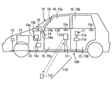
- the forced ventilation apparatus 100 of 1st Embodiment is an apparatus which performs the forced ventilation of the indoor 14 by operating the air blower 18a of the air conditioner 18 for vehicles, for example in the state in which the indoor 14 of the vehicle 10 was left at high temperature. is there.
- the forced ventilation device 100 is a device in which the power window device 17 and the air conditioner 18 are associated with a smart entry system 110 that locks and unlocks the door 15 of the vehicle 10 and a timer 120 for timekeeping.
- the vehicle 10 is, for example, an engine vehicle including an engine 11 as a driving source for traveling.
- the driver's seat of the vehicle 10 is set on the right side of the vehicle and is a so-called right-hand drive vehicle.
- the ignition switch 12 for turning on the power is turned on, power is supplied from the vehicle battery to the engine 11 and other devices described later.
- the ignition switch 12 is connected to a vehicle interior network bus 13 such as a LIN (Local Interconnect Network) or a CAN (Controller Area Network registered trademark).
- vehicle interior network bus 13 such as a LIN (Local Interconnect Network) or a CAN (Controller Area Network registered trademark).
- the ignition switch 12 may be connected to the vehicle interior network bus 13 via, for example, an ignition switch control unit.
- the vehicle 10 is provided with left and right (driver's seat side and passenger's side) front seat side doors 15a and left and right rear seat side doors 15b as doors 15 for a user to get on and off. It is a type of vehicle.
- Each door 15a, 15b is provided with a door knob 15c that serves as a grip when opening and closing.
- the door 15 is provided with a vertically openable / closable window (window glass) 16.
- the window 16 includes a front seat side window 16a provided on the front seat side door 15a and a rear seat side window 16b provided on the rear seat side door 15b. Therefore, each of the windows 16a and 16b has four settings, front, rear, left and right, like the doors 15a and 15b.
- the power window device 17 may be used as an example of an opening / closing mechanism that opens and closes the windows 16a and 16b by moving the windows 16a and 16b up and down.
- the power window device 17 includes a window motor 17a that moves the windows 16a and 16b up and down, and a body ECU 17b that controls the operation of the window motor 17a.
- the window motor 17a is provided in each door 15a, 15b so as to correspond to each window 16a, 16b.
- the body ECU 17b is connected to the vehicle interior network bus 13.
- the air conditioner 18 is an apparatus that air-conditions the interior 14 of the vehicle 10, and is disposed inside the instrument panel 19 in the interior 14.
- the air conditioner 18 includes a blower 18a, an air conditioning unit 18b, an air conditioning ECU 18c, and the like.
- the blower 18a includes a fan and a motor, and introduces air in the room 14 (inside air) or outside air (outside air) of the vehicle 10 into the air conditioning unit 18b, and a blower duct 18d provided on the downstream side of the air conditioning unit 18b. And it is the apparatus which blows into the room 14 through the blower outlet 18e opened to the room 14.
- the outlet 18 e is provided in the instrument panel 19.
- the air conditioning unit 18b includes a cooling heat exchanger provided in the refrigeration cycle apparatus in which the refrigerant is circulated and a heating heat exchanger provided in a heater circuit in which the engine cooling water is circulated, and air is blown by the blower 18a.
- the air is cooled or heated to adjust the temperature of the blown air so that the set temperature is set by the user.
- the air conditioning ECU 18c is an air conditioning control unit that controls operations of the blower 18a and the air conditioning unit 18b.
- the air conditioning ECU 18 c is connected to the vehicle interior network bus 13.
- the air conditioner 18 is provided with an air conditioner switch for operating the refrigeration cycle apparatus (cooling operation) and an inside / outside air switching switch for introducing either the inside air or the outside air.
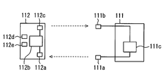
- the smart entry system 110 can lock and unlock the doors 15a and 15b without directly inserting keys into the key cylinders of the doors 15a and 15b and without manually operating the portable device 112. It is a system to do. As shown in FIGS. 1 and 2, the smart entry system 110 includes a vehicle-side main body 111 and a portable device 112, and the ignition switch 12, power window device 17, and air conditioner 18 described above are included. It is configured to work together.
- the vehicle-side main body 111 is provided in the vehicle 10 and includes a main body transmission unit 111a, a main body reception unit 111b, a main body control unit 111c, and the like.
- the main body transmission unit 111a uses an LF (low frequency) wave as a long wave to transmit an interrogation signal to the portable device 112 outside or inside the vehicle 10 (indoor 14) by wireless communication (radio wave communication).
- the main body transmission unit 111a is formed as a transmission antenna that transmits an interrogation signal.
- the main body transmission unit 111a is provided in each of the left and right front seat side doors 15a.
- the interrogation signal from the main body transmission unit 111a does not require an external trigger and is transmitted intermittently (at a predetermined transmission interval) when the vehicle is stopped.
- the main body reception unit 111b is a reception unit that receives a response signal by an RF (Radio Frequency) wave as a high frequency transmitted from the portable device 112.
- the main body reception unit 111b is formed as a reception antenna that receives a response signal.
- the main body reception unit 111b can receive a response signal from the portable device 112 from the outside or the inside (the room 14) of the vehicle 10.
- the main body receiver 111b outputs the received response signal to the main body controller 111c.
- the main body control unit 111c is a control unit that outputs an interrogation signal to the portable device 112 via the main body transmission unit 111a and receives a response signal from the portable device 112 via the main body reception unit 111b. Yes.
- the main body control unit 111c corresponds to the control unit of the present disclosure.
- the main body controller 111 c is connected to the vehicle interior network bus 13.
- the main body control unit 111c When the main body control unit 111c receives a response signal from the portable device 112 in the detection area when the doors 15a and 15b are locked or unlocked, the main body control unit 111c is registered in advance in the main body control unit 111c. Check the authentication signal. Further, when this collation is successful and the user performs an operation such as touching the door knob 15c, a command for locking or unlocking the lock mechanism of each door 15a, 15b is output. It has become.
- the operation such as contact with the door knob 15c is, for example, an operation such as touching a predetermined part of the door knob 15c or grasping the door knob 15c.
- the detection area is an area in which the portable device 112 (mobile control unit 112b) can respond to the interrogation signal from the main body transmission unit 111a, and a range in which an inquiry signal can reach from the main body transmission unit 111a. It becomes the area of.
- the detection area is an area facing the front seat side door 15a (left and right) mainly provided with the main body transmission unit 111a, and the user carrying the portable device 112 approaches the vehicle 10 in front of him The distance is short enough to see the vehicle (for example, a distance of about 5 m to 10 m).
- the portable device 112 is a portable key carried by the user, and includes a portable reception unit 112a, a portable control unit 112b, a portable transmission unit 112c, a lock button 112d, an unlock button 112e, and the like.
- the mobile receiver 112a is a receiver that receives the interrogation signal transmitted from the main body transmitter 111a and outputs the signal to the mobile controller 112b described later.
- the portable receiving unit 112a is formed as a receiving antenna that receives an interrogation signal.
- the mobile control unit 112b is a control unit that outputs a response signal required for collation to the mobile transmission unit 112c based on the interrogation signal input from the mobile reception unit 112a.
- the portable control unit 112b sends a request signal corresponding to each input signal to the main body control unit 111c. Is output (details will be described later).
- the portable transmitter 112c is a transmitter that transmits a response signal or a request signal from the portable controller 112b to the main body receiver 111b.
- the portable transmitter 112c is formed as an antenna that transmits a response signal or a request signal.
- the lock button 112d is an input unit that performs an input for locking the door 15 regardless of an interrogation signal when pressed by the user. Specifically, the lock button 112d generates a door lock request signal for requesting locking (locking) of the door 15, and outputs the door lock request signal to the portable control unit 112b. The door lock request signal is transmitted from the portable control unit 112b to the main body control unit 111c.
- the unlock button 112e is an input unit that performs an input for unlocking the door 15 regardless of the call signal when pressed by the user. Specifically, the unlock button 112e generates a door unlock request signal for requesting unlocking (unlocking) of the door 15, and outputs the door unlock request signal to the portable control unit 112b. The door unlock request signal is transmitted from the portable control unit 112b to the main body control unit 111c.
- Each of the buttons 112d and 112e is basically a button that is selected and pressed according to each request. However, apart from that, in the present embodiment, each button 112d, 112e generates a forced ventilation request signal for performing forced ventilation when operated in a manner different from the pressing operation originally used. , And can be output to the portable control unit 112b.
- the forced ventilation request signal is transmitted from the portable control unit 112b to the main body control unit 111c.
- the operation for generating the forced ventilation request signal is different from the originally used pressing operation. For example, when are sequentially pressed.
- the timer 120 serves as a time measuring means for measuring the operation time of the blower 18a during forced ventilation control, which will be described later, and is connected to the main body control unit 111c.
- the user sets the forced ventilation mode in advance by pressing the buttons 112d and 112e of the portable device 112 in advance. For example, the user generates a forced ventilation request signal by simultaneously pressing both the two buttons 112d and 112e, or pressing the two buttons 112d and 112e in order, and controls the main body from the portable control unit 112b. It is transmitted to the unit 111c.
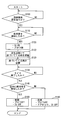
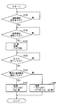
- forced ventilation control is performed based on the control flow shown in FIG.
- the situation in which this forced ventilation mode is implemented is a scene in which the vehicle 10 is stopped in a parking lot under hot weather, for example, and the user approaches the vehicle to finish driving and drive again.
- step S100 the main body control unit 111c determines whether or not the forced ventilation mode is set. If it is determined that there is a setting, the process proceeds to step S110. If it is determined NO in step S100, step S100 is repeated.
- step S110 the main body control unit 111c determines whether or not a user has been detected. Specifically, the main body control unit 111c determines whether or not the portable device 112 is detected in the detection area based on a response signal from the portable device 112 carried by the user. Furthermore, the main body control unit 111c determines whether or not the response signals can be collated.
- the main body control unit 111c transmits an interrogation signal intermittently when the vehicle is stopped.
- the portable device 112 can detect a call signal, and transmits a response signal to the main body control unit 111c in response to the call signal.
- the main body control unit 111c confirms the presence of the portable device 112 in the detection area.
- the main body control unit 111c collates the response signal with the authentication signal that it has, and if the collation is successful, the portable device 112 authenticates that it is the correct portable device 112 set in the vehicle 10. To do.
- step S110 if the main body control part 111c performs affirmation determination, ie, the detection and authentication of the portable device 112, it will progress to step S120, and if negative determination is carried out, it will repeat step S110.
- step S120 the main body controller 111c turns on the ignition switch 12, opens the window 16, and operates the blower 18a to perform forced ventilation.
- the main body control unit 111c directly or when the ignition switch 12 connected via the vehicle interior network bus 13 is provided with a control unit for the ignition switch, turns on the ignition switch. Outputs a command.
- the main body control unit 111c outputs a command for opening the window 16 to the body ECU 17b connected via the vehicle interior network bus 13.
- the window 16 to be opened is, for example, a rear seat side window 16b.
- the rear seat side window 16b is opened at a predetermined opening degree determined in advance, for example.
- the main body control unit 111c outputs a command for operating the blower 18a to the air conditioning ECU 18c connected via the vehicle interior network bus 13. For example, the blower 18a is operated at full power when a MAX voltage is applied. The blower 18a is activated regardless of whether the air conditioner switch in the air conditioner 18 is on or off and the setting of the inside / outside air changeover switch. At this time, the main body control unit 111c starts measuring time by the timer 120.
- step S130 the main body control unit 111c determines whether or not the time measured by the timer 120 has expired. Specifically, the main body control unit 111c determines whether or not the time measured by the timer 120, that is, the operating time of the blower 18a has passed a predetermined time. If the determination is affirmative in step S130, the main body control unit 111c proceeds to step S140. If the determination is negative, step S130 is repeated.
- step S140 the main body control unit 111c determines whether or not the user (mobile device 112) has been detected in the room 14. Specifically, the main body control unit 111 c determines whether or not the portable device 112 is in the room 14 based on whether or not the portable device 112 has responded to the interrogation signal transmitted to the room 14. This indicates whether the user approaching the vehicle 10 performs a contact operation on the door knob 15c, unlocks the door 15, and gets on the vehicle 10.
- step S140 the main body control unit 111c closes the window 16 and stops the blower 18a in step S150, and ends the forced ventilation by turning off the ignition switch 12. Specifically, in response to this step S150, the main body control unit 111c outputs a command for closing the window 16 to the body ECU 17b, and also causes the air-conditioning ECU 18c to stop the blower 18a. This is handled by outputting an OFF command to the ignition switch 12 (or the control unit for the ignition switch).
- step S140 the main body control unit 111c closes the window 16, stops the blower 18a, locks the door 15, and turns off the ignition switch 12 in step S160.
- the procedure for closing the window 16, stopping the blower 18a, and turning off the ignition switch 12 are the same as in step S150.
- the main body control unit 111 c locks the door 15.
- the door 15 is not unlocked (it remains locked). It will be. In this state, the main body control unit 111c maintains the locked state of the door 15.
- the portable device 112 in the smart entry system 110 and the main body control unit 111c are used, and the main body control unit is exchanged between the interrogation signal and the response signal by radio waves.
- 111c detects that the portable device 112 has entered the detection area.
- the main body control unit 111c is set in advance for forced ventilation mode.
- the response signal is successfully verified, the main body control unit 111c turns on the ignition switch 12 and opens the window 16 of the vehicle 10 by the power window device 17.
- the forced ventilation is performed by operating the blower 18a of the air conditioner 18.
- the window 16 is opened, so that effective ventilation is performed. At this time, the user is in the detection area with respect to the vehicle 10, and even if the window 16 is opened, forced ventilation is performed in front of the user's eyes, so security can be secured. It will be a thing.
- the window 16 opened at the time of forced ventilation is the window 16b on the rear seat side of the vehicle 10.
- the outlet 18e of the air conditioner 18 in the vehicle 10 is provided in the front part (instrument panel 19) of the room 14. Therefore, by setting the window 16 to be opened as the rear seat side window 16b, the air to be blown flows from the front to the rear of the room 14 and escapes to the outside from the rear seat side window 16b. Overall effective ventilation is possible.
- a timer 120 that measures the operating time of the blower 18a is provided, and the main body control unit 111c, when the operating time of the blower 18a measured by the timer 120 passes a predetermined time, The opened window 16 is closed, the blower 18a is stopped, and the ignition switch 12 is turned off.
- the main body control unit 111c locks the door 15 if the indoor unit 14 does not detect the portable device 112 even when the operation time of the blower 18a timed by the timer 120 exceeds a predetermined time. It is supposed to be.
- FIG. 4 A second embodiment is shown in FIG. This embodiment opens the window 16 on the approaching side so that the user can grasp which side of the vehicle 10 is approaching when performing forced ventilation with respect to the first embodiment. It is what I did.
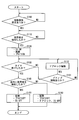
- the flowchart of FIG. 4 is obtained by changing step S120 of FIG. 3 described in the first embodiment to steps S121, S122, and S123.
- step S110 determines in step S110 that the portable device 112 is in the detection area and has successfully verified the response signal
- step S121 the main body control unit 111c first turns on the ignition switch 12 and activates the blower 18a. And immediately start forced ventilation.
- step S122 the main body control unit 111c sends an interrogation signal from the main body transmission unit 111a in the left and right front seat doors 15a to the right outside (driver seat side outside) and the left outside (passenger seat side outside).
- the main body control unit 111c sends an interrogation signal from the main body transmission unit 111a in the left and right front seat doors 15a to the right outside (driver seat side outside) and the left outside (passenger seat side outside).
- the portable device 112 responds to the interrogation signal transmitted from the right front seat door 15a among the left and right front seat doors 15a, it is recognized that the user is approaching from the right side of the vehicle 10.
- the portable device 112 responds to the interrogation signal transmitted from the left front seat door 15a among the left and right front seat doors 15a, the user grasps that the user is approaching from the left side of the vehicle 10. Is done.
- step S123 the main body control unit 111c opens the window 16 on the side where the user approaches when opening the window 16.
- the window to be opened is the side on which the user approaches, and it is desirable to use the rear seat side window 16b of the front seat side and the rear seat side.
- FIG. 5 A third embodiment is shown in FIG.
- the blower 18a when the blower 18a is operated by performing forced ventilation with respect to the first embodiment, when the user requests an operation to unlock the door 15, the blower 18a is operated. The door 15 is unlocked as it is.
- the flowchart of FIG. 5 is obtained by adding steps S131 and S132 to FIG. 3 described in the first embodiment.
- step S130 when the main body control unit 111c determines in step S130 after step S120 that the operation time of the blower 18a by the timer 120 has not exceeded the predetermined time, the process proceeds to step S131, and the user applies the door knob 15c to the door knob 15c. It is determined whether or not there has been an operation such as contact (operation to request unlocking of the door 15).
- step S131 If the determination in step S131 is affirmative, the body control unit 111c unlocks the door 15 while operating the blower 18a in step S132, and returns to step S130.
- FIG. 6 A fourth embodiment is shown in FIG.
- the engine 11 is started when the portable device 112 is detected in the room 14 after the blower 18a is operated for a predetermined time by performing forced ventilation with respect to the first embodiment.
- the flowchart of FIG. 6 is obtained by changing step S150 of FIG. 3 described in the first embodiment to step S151.
- the main body control unit 111c is associated with a start switch for starting the engine 11.
- the main body control unit 111c can start the engine 11 by requesting the start switch to start the engine 11.
- the main body control unit 111c determines whether the user (portable device 112) has been detected in the room 14 in step S140.
- step S140 the main body control unit 111c closes the window 16 and stops the blower 18a in step S151 to end forced ventilation, and also starts the engine 11.
- forced ventilation is automatically terminated when a predetermined time has elapsed after the operation of the blower 18a. Furthermore, if the portable device 112 is detected in the room 14, it is determined that the user has boarded. In this situation, the user can start driving immediately by starting the engine 11. That is, it is possible to smoothly perform the forced ventilation, end the operation, and start the subsequent operation.
- a dedicated mechanical switch provided on a vehicle operation panel or the like in the instrument panel 19 or a touch switch on a vehicle information display screen may be used.
- a terminal connected to the main body control unit 111c may be used.
- the main body transmission unit 111a is described as being provided on the left and right front seat doors 15a.
- the main body transmission unit 111a is also provided on the left and right rear seat doors 15b and further on the rear trunk. May be. Thereby, it becomes possible to detect the user (portable device 112) approaching the vehicle in a wider range.
- the main body transmission unit 111a is provided on the left and right front seat side doors 15a, the left and right rear seat side doors 15b, and further on the rear trunk. The user may be able to select and set whether to function.
- the window opened when implementing forced ventilation was made into the rear seat side window 16b, it is not limited to this, The ventilation capacity of the air blower 18a, or the indoor 14 to ventilate Depending on the area and the like, the front seat side window 16a may be opened. Furthermore, the window that can be opened may be a combination of the rear seat side window 16b and the front seat side window 16a (other windows).
- the window that can be opened may be set by the user to select which part of the window is to be opened when the first forced ventilation mode is set.
- the opening of the window 16 when performing forced ventilation is a predetermined opening.
- the predetermined opening means an opening having an arbitrary size such as a small opening, a medium opening, and a large opening. Furthermore, the user may be allowed to set the degree of opening when setting the first forced ventilation mode.
- the applied voltage of the blower 18a that is activated during forced ventilation is the MAX voltage, but is not limited thereto, and may be set as an arbitrary voltage.
Landscapes
- Physics & Mathematics (AREA)
- Thermal Sciences (AREA)
- Engineering & Computer Science (AREA)
- Mechanical Engineering (AREA)
- Lock And Its Accessories (AREA)
- Air-Conditioning For Vehicles (AREA)
Abstract
車両(10)の室内(14)が高温に放置された状況で、車両(10)用の空調装置(18)の送風機(18a)を作動させて、室内(14)内の強制換気を行う強制換気装置において、制御部(111c)は、ユーザによる強制換気のためのモード設定が予め成されており、ユーザと共に携帯機(112)が、車両(10)に近づいて、応答信号によって携帯機(112)の検知を可能とする所定の検知エリアに入り、応答信号の照合に成功すると、車両(10)のイグニッションスイッチ(12)をオンさせて、開閉機構(17)によって窓(16、16a、16b)を開くと共に、空調装置(18)に対して送風機(18a)の作動を指示する。これにより、ユーザの操作による手間をなくし、またセキュリティを確保できる。
Description
本出願は、当該開示内容が参照によって本出願に組み込まれた、2014年11月4日に出願された日本特許出願2014-224474を基にしている。
本開示は、車両ドアの施錠および解除を行うスマートエントリーシステムを用いた強制換気装置に関するものである。
従来の自動車用強制換気装置として、例えば、特許文献1に記載されたものが知られている。特許文献1の強制換気装置においては、キーレスエントリー装置からの換気指示信号に基づいてパワーウィンド装置のパワーウィンドモータと、空調装置のブロワモータと、空調装置の内外気切替えアクチュエータとに強制換気開始の制御指令が出力される。そして、この制御指令に基づいて、ドアガラスが下げられると共に、外気導入による送風が行われて、車室内が強制換気されるようになっている。
換気指示信号を出力するにあたっては、キーレスエントリー装置に設けられたリモコン送信機を用いて、ユーザが遠隔操作することで行われるようになっている。
これにより、炎天下の駐車等により高温となった車室内温度を乗車に先立って予め下げることができるようになっている。
しかしながら、上記特許文献1の強制換気装置では、キーレスエントリー装置を活用したものであるので、換気を行う際に、ユーザは、リモコン送信機を都度、操作する必要が生ずる。また、特許文献1の強制換気装置は、車両遠方からのリモコン送信機の操作(遠隔操作)によるものであるので、車両の近くにユーザ本人がいない状況にもかかわらずドアガラスが下げられることになり、セキュリティが確保されない場合がある。
本開示の目的は、上記問題に鑑み、ユーザの操作による手間をなくし、またセキュリティを確保できる強制換気装置を提供することにある。
本開示の一態様によると、強制換気装置は、車両の室内が高温に放置された状況で、車両用の空調装置の送風機を作動させて、室内の強制換気を行う。強制換気装置は、携帯機と、制御部と、開閉機構と、を備える。携帯機は、ユーザによって携帯され、スマートエントリーシステムに用いられる。制御部は、車両に設けられて、携帯機に対する呼掛け信号を電波送信する。制御部は、呼掛け信号に電波応答して携帯機から電波送信される応答信号を照合することで、車両のドアの施錠あるいは解錠を行う。開閉機構は、ドアの窓を開閉する。ユーザによる強制換気のためのモードが予め設定されている場合かつ、ユーザと共に携帯機が、車両に近づいて、携帯機の応答信号が制御部によって検知可能な所定の検知エリアに入り、応答信号の照合に成功した場合、制御部は、車両のイグニッションスイッチをオンさせて、開閉機構によって窓を開くと共に、空調装置に対して送風機の作動を指示する。
これによれば、スマートエントリーシステムにおける携帯機と、制御部とを用いており、電波による呼掛け信号と応答信号とのやり取りによって、制御部は、携帯機が検知エリア内に入ったことを検知する。そして、制御部は、強制換気のためのモードが予め設定されており、応答信号の照合に成功すると、イグニッションスイッチをオンさせて、開閉機構によって車両の窓を開き、空調装置の送風機を作動させることで強制換気を実施する。
よって、携帯機を携帯するユーザが、車両に近づくことで、自動的に強制換気が実施されるので、ポケットやバッグ等から携帯機を取り出して、手動操作する必要がなく、ユーザの操作の手間を無くすことができる。
また、強制換気を実施するにあたって、窓が開かれることで、効果的な換気が行われる。このとき、ユーザは、車両に対して検知エリア内にいることになり、窓が開かれた状態であっても、ユーザの眼前で実施される強制換気となるので、セキュリティも確保できる。
以下に、図面を参照しながら本開示を実施するための複数の形態を説明する。各形態において先行する形態で説明した事項に対応する部分には同一の参照符号を付して重複する説明を省略する場合がある。各形態において構成の一部のみを説明している場合は、構成の他の部分については先行して説明した他の形態を適用することができる。各実施形態で具体的に組み合わせが可能であることを明示している部分同士の組み合わせばかりではなく、特に組み合わせに支障が生じなければ、明示していなくても実施形態同士を部分的に組み合せることも可能である。
(第1実施形態)
第1実施形態における強制換気装置100について、図1~図3を用いて説明する。第1実施形態の強制換気装置100は、例えば、車両10の室内14が高温に放置された状態で、車両用の空調装置18の送風機18aを作動させて、室内14の強制換気を行う装置である。強制換気装置100は、車両10のドア15の施錠および解錠を行うスマートエントリーシステム110、および計時用のタイマー120に、パワーウィンド装置17および空調装置18が関連付けされた装置となっている。
(第1実施形態)
第1実施形態における強制換気装置100について、図1~図3を用いて説明する。第1実施形態の強制換気装置100は、例えば、車両10の室内14が高温に放置された状態で、車両用の空調装置18の送風機18aを作動させて、室内14の強制換気を行う装置である。強制換気装置100は、車両10のドア15の施錠および解錠を行うスマートエントリーシステム110、および計時用のタイマー120に、パワーウィンド装置17および空調装置18が関連付けされた装置となっている。
図1に示すように、車両10は、例えば、走行用駆動源としてのエンジン11を備えるエンジン車両である。車両10の運転席は、車両の右側に設定されており、いわゆる右ハンドル車となっている。電源投入用のイグニッションスイッチ12がオンされると、車両バッテリからエンジン11を初め、後述する各装置に電力が供給されるようになっている。
イグニッションスイッチ12は、例えば、LIN(Local Interconnect Network)や、CAN(Controller Area Network 登録商標)等の車室内ネットワークバス13に接続されている。尚、イグニッションスイッチ12は、例えば、イグニッションスイッチ用の制御部を介して、車室内ネットワークバス13に接続されるようにしてもよい。
車両10にはユーザが乗降するためのドア15として、左右(運転席側と助手席側)の前席側ドア15a、および左右の後席側ドア15bが設けられており、車両10は4ドアタイプの車両となっている。各ドア15a、15bには、開閉時の握り手となるドアノブ15cがそれぞれ設けられている。また、ドア15には上下開閉式の窓(窓ガラス)16が設けられている。窓16は、前席側ドア15aに設けられた前席側窓16aと、後席側ドア15bに設けられた後席側窓16bとがある。よって、各窓16a、16bも各ドア15a、15bと同様に前後左右の4つの設定となっている。
パワーウィンド装置17は、上記の各窓16a、16bを昇降させることで、各窓16a、16bを開閉する開閉機構の一例として用いられてもよい。パワーウィンド装置17は、各窓16a、16bを昇降させるウィンドモータ17aと、このウィンドモータ17aの作動を制御するボディECU17bとを備えている。ウィンドモータ17aは、各窓16a、16bに対応するように各ドア15a、15bにそれぞれ設けられている。ボディECU17bは、車室内ネットワークバス13に接続されている。
空調装置18は、車両10の室内14の空調を行う装置であり、室内14のインストルメントパネル19の内側に配置されている。空調装置18は、送風機18a、空調部18b、および空調ECU18c等を備えている。
送風機18aは、ファンとモータと備え、室内14の空気(内気)、あるいは車両10の外部空気(外気)を空調部18bに導入して、空調部18bの下流側に設けられた送風ダクト18d、および室内14に開口する吹出し口18eを介して室内14に送風する機器となっている。吹出し口18eは、インストルメントパネル19に設けられている。
空調部18bは、冷媒が循環される冷凍サイクル装置に設けられた冷却用熱交換器と、エンジン冷却水が循環されるヒータ回路に設けられた加熱用熱交換器とを備え、送風機18aによって送風された空気を冷却あるいは加熱して、ユーザの設定する設定温度となるように送風空気の温度を調節する機器となっている。
空調ECU18cは、上記の送風機18a、および空調部18b等の作動を制御する空調制御部である。空調ECU18cは、車室内ネットワークバス13に接続されている。
尚、空調装置18には、冷凍サイクル装置を作動させる(冷房作動)ためのエアコンスイッチ、および内気あるいは外気のいずれかを導入するための内外気切替えスイッチが設けられている。
スマートエントリーシステム110は、各ドア15a、15bのキーシリンダーに直接、キーを差し込むことなく、更には、携帯機112を手操作等することなく、各ドア15a、15bの施錠および解錠を可能とするシステムとなっている。スマートエントリーシステム110は、図1、図2に示すように、車両側本体部111と、携帯機112とを備えており、且つ、上記のイグニッションスイッチ12、パワーウィンド装置17、および空調装置18が連動するように構成されている。
車両側本体部111は、車両10に設けられており、本体送信部111a、本体受信部111b、および本体制御部111c等を備えている。
本体送信部111aは、長波としてのLF(low Frequency)波を用い、無線通信(電波通信)によって、車両10の外部あるいは内部(室内14)の携帯機112に対して呼掛け信号を送信する送信部となっている。本体送信部111aは、呼掛け信号を送信する送信用アンテナとして形成されている。本体送信部111aは、例えば、左右の前席側ドア15aのそれぞれに設けられている。本体送信部111aによる呼掛け信号は、外部からのトリガを必要とせず、車両の停車時において間欠的に(所定の送信間隔で)送信されるものとなっている。
本体受信部111bは、携帯機112から送信される高周波としてのRF(Radio Frequency)波による応答信号を受信する受信部となっている。本体受信部111bは、応答信号を受信する受信用アンテナとして形成されている。本体受信部111bは、車両10の外部あるいは内部(室内14)からの携帯機112による応答信号を受信できるようになっている。本体受信部111bは、受信した応答信号を本体制御部111cに出力するようになっている。
本体制御部111cは、携帯機112に対して本体送信部111aを介して呼掛け信号を出力すると共に、携帯機112からの応答信号を、本体受信部111bを介して受信する制御部となっている。本体制御部111cは、本開示の制御部に対応する。本体制御部111cは、車室内ネットワークバス13に接続されている。
本体制御部111cは、各ドア15a、15bの施錠時あるいは解錠時において、検知エリア内で、携帯機112からの応答信号を受けると、受けた応答信号と本体制御部111cに予め登録された認証用信号とを照合する。更に、この照合が成功して、且つ、ユーザによるドアノブ15cへの接触等の操作があると、各ドア15a、15bのロック機構に対して施錠あるいは解錠を行うための指令を出力するようになっている。ドアノブ15cへの接触等の操作は、例えば、ドアノブ15cの所定部位に触れる、あるいはドアノブ15cを握る等の操作である。
ここで、検知エリアとは、本体送信部111aからの呼掛け信号に対して、携帯機112(携帯制御部112b)が応答可能となる領域であり、本体送信部111aから問合せ信号が届き得る範囲の領域となる。具体的には、検知エリアは、主に本体送信部111aが設けられた前席側ドア15a(左右)と向かい合う領域であり、携帯機112を携帯するユーザが、車両10に近づいて、眼前に車両を見て取れる程度の近距離(例えば、5m~10m程度の距離)となっている。
一方、携帯機112は、ユーザが携帯する携帯型キーであり、携帯受信部112a、携帯制御部112b、携帯送信部112c、ロックボタン112d、およびアンロックボタン112e等を備えている。
携帯受信部112aは、本体送信部111aから送信される呼掛け信号を受信して、後述する携帯制御部112bに出力する受信部となっている。携帯受信部112aは、呼掛け信号を受信する受信用アンテナとして形成されている。
携帯制御部112bは、携帯受信部112aから入力された呼掛け信号に基づいて、照合に必要とされる応答信号を携帯送信部112cに出力する制御部となっている。また、携帯制御部112bは、ロックボタン112d、およびアンロックボタン112eのいずれか、あるいは両者の押下操作に伴う入力信号があると、本体制御部111cに対して、各入力信号に応じた要求信号を出力するようになっている(詳細後述)。
携帯送信部112cは、携帯制御部112bからの応答信号、あるいは要求信号を本体受信部111bに送信する送信部となっている。携帯送信部112cは、応答信号、あるいは要求信号を送信するアンテナとして形成されている。
ロックボタン112dは、ユーザによって押下されることで、呼掛け信号に関係なく、ドア15の施錠のための入力を行う入力部となっている。具体的には、ロックボタン112dは、ドア15のロック(施錠)を要求するドアロック要求信号を生成して、携帯制御部112bに出力するようになっている。ドアロック要求信号は、携帯制御部112bから本体制御部111cに送信される。
アンロックボタン112eは、ロックボタン112dと同様に、ユーザによって押下されることで、呼掛け信号に関係なく、ドア15の解錠のための入力を行う入力部となっている。具体的には、アンロックボタン112eは、ドア15のアンロック(解錠)を要求するドアアンロック要求信号を生成して、携帯制御部112bに出力するようになっている。ドアアンロック要求信号は、携帯制御部112bから本体制御部111cに送信される。
上記の各ボタン112d、112eは、基本的には、それぞれ、上記の各要求に応じていずれか1つが選択されて押下されるボタンとなっている。しかしながら、それとは別に、本実施形態では、各ボタン112d、112eは、本来使用される押下操作とは異なる要領で操作されたときに、強制換気を実施するための強制換気要求信号を生成して、携帯制御部112bに出力できるようになっている。強制換気要求信号は、携帯制御部112bから本体制御部111cに送信される。
強制換気要求信号を生成するための、本来使用される押下操作とは異なる要領の操作とは、例えば、2つのボタン112d、112eの両者が同時に押下された場合、あるいは、2つのボタン112d、112eが順番に押下された場合等とすることができる。
タイマー120は、後述する強制換気制御時の送風機18aの作動時間を計時する計時手段となっており、本体制御部111cに接続されている。
上記のように構成される強制換気装置100の作動について、図3のフローチャートを加えて説明する。尚、図3のフローチャートは、本体制御部111cが行う制御内容を示している。
まず、ユーザは、特に夏場における強制換気が必要であるとすると、事前に、携帯機112の各ボタン112d、112eの押下操作によって、強制換気モードの設定を行っておく。例えば、ユーザは、2つのボタン112d、112eの両者を同時に押下する、あるいは、2つのボタン112d、112eを順番に押下する等によって、強制換気要求信号を生成して、携帯制御部112bから本体制御部111cに送信しておく。
強制換気モード設定が成された場合は、図3に示す制御フローに基づいて、強制換気制御が実施されることになる。この強制換気モードが実施されるシチュエーションは、例えば炎天下で駐車場に車両10が停車されており、用事を終えてユーザが再び運転するために車両に近づいていく場面である。
まず、ステップS100で、本体制御部111cは、強制換気モードの設定があるか否かを判定し、設定ありと判定するとステップS110に進む。ステップS100で、否と判定すれば、ステップS100を繰り返す。
ステップS110では、本体制御部111cは、ユーザを検知したか否かを判定する。具体的には、本体制御部111cは、ユーザが携帯する携帯機112からの応答信号に基づいて、検知エリア内に携帯機112を検知したか否かを判定する。更には、本体制御部111cは、応答信号の照合ができたか否かを判定する。
つまり、本体制御部111cは、停車時において間欠的に呼掛け信号を送信している。ユーザが検知エリア内に入ると、携帯機112は、呼掛け信号を検知可能となって、この呼掛け信号に対して応答信号を本体制御部111cに送信する。これによって、本体制御部111cは、検知エリア内における携帯機112の存在を確認するのである。このとき、本体制御部111cは、応答信号と、自身が有する認証用信号とを照合し、照合に成功すると、この携帯機112は、車両10に設定された正しい携帯機112であることを認証する。
そして、ステップS110で、本体制御部111cは、肯定判定、つまり携帯機112の検知と認証とを行うと、ステップS120に進み、否定判定するとステップS110を繰り返す。
ステップS120では、本体制御部111cは、イグニッションスイッチ12をオンにし、窓16を開けて、送風機18aを作動させることで強制換気を実施する。具体的には、本体制御部111cは、車室内ネットワークバス13を介して接続されるイグニッションスイッチ12に直接、あるいは、イグニッションスイッチ用の制御部が設けられる場合は、この制御部にイグニションスイッチオンの指令を出力する。
また、本体制御部111cは、車室内ネットワークバス13を介して接続されるボディECU17bに対して、窓16を開けるための指令を出力する。開かれる窓16は、例えば、後席側窓16bとなっている。後席側窓16bは、例えば、予め定められた所定の開度で開かれるようになっている。
また、本体制御部111cは、車室内ネットワークバス13を介して接続される空調ECU18cに対して、送風機18aを作動させるための指令を出力する。送風機18aは、例えば、MAX電圧が印加されてフルパワーで作動するようになっている。送風機18aは、空調装置18におけるエアコンスイッチのオンオフ、内外気切替えスイッチの設定に関わらず、作動されるようになっている。このとき、本体制御部111cは、タイマー120による計時をスタートさせる。
次に、ステップS130で、本体制御部111cは、タイマー120による計時がタイムアップしたか否かを判定する。具体的には、本体制御部111cは、タイマー120による計時時間、つまり、送風機18aの作動時間が、予め定めた所定時間を過ぎたか否かを判定する。ステップS130で、本体制御部111cは、肯定判定するとステップS140に進み、否定判定するとステップS130を繰り返す。
ステップS140では、本体制御部111cは、室内14にユーザ(携帯機112)を検知したか否かを判定する。具体的には、本体制御部111cは、室内14に送信している呼掛け信号に対して携帯機112が応答したか否かをもって、室内14に携帯機112があるか否かを判定する。これは、車両10に近づいたユーザがドアノブ15cへの接触操作を行い、ドア15を解錠して、車両10に乗車したか否かを示す内容となる。
ステップS140で肯定判定すると、本体制御部111cは、ステップS150で、窓16を閉じ、送風機18aを停止させ、併せて、イグニッションスイッチ12をオフにすることで強制換気を終了させる。このステップS150での対応は、具体的には、本体制御部111cは、ボディECU17bに対して、窓16を閉めるための指令を出力し、また、空調ECU18cに対して、送風機18aを停止させるための指令を出力し、イグニッションスイッチ12(あるいはイグニッションスイッチ用の制御部)に対するオフの指令を出力することで対応する。
一方、ステップS140で否定判定すると、本体制御部111cは、ステップS160で、窓16を閉じ、送風機18aを停止させ、ドア15の施錠を行い、併せて、イグニッションスイッチ12をオフにする。窓16の閉成、送風機18aの停止、イグニッションスイッチ12のオフ要領は、上記ステップS150と同様である。
上記実施制御項目のうち、ドア15の施錠については、ユーザが室内14内に一旦乗車して、例えば別の用事を思い出して、車から降りた場合であると、ドア15は解錠された状態となっている可能性があるので、本体制御部111cは、ドア15の施錠を行う。また、ユーザが車両10に近づいていったものの、途中で別の用事を思い出して、乗車せずに離れていった場合であると、ドア15の解錠は行われていない(施錠のまま)ことになる。この状態であると、本体制御部111cは、ドア15の施錠状態を維持する。
以上のように、本実施形態では、スマートエントリーシステム110における携帯機112と、本体制御部111cとを用いたものとなっており、電波による呼掛け信号と応答信号とのやり取りによって、本体制御部111cは、携帯機112が検知エリア内に入ったことを検知する。そして、本体制御部111cは、強制換気のためのモード設定が予め成されており、応答信号の照合に成功すると、イグニッションスイッチ12をオンさせて、パワーウィンド装置17によって車両10の窓16を開き、空調装置18の送風機18aを作動させることで強制換気を実施する。
よって、携帯機112を携帯するユーザが、車両10に近づくことで、自動的に強制換気が実施されるので、ポケットやバッグ等から携帯機112を取り出して、手動操作する必要がなく、ユーザの操作の手間を無くすことができる。
また、強制換気を実施するにあたって、窓16が開かれることで、効果的な換気が行われる。このとき、ユーザは、車両10に対して検知エリア内にいることになり、窓16が開かれた状態であっても、ユーザの眼前で実施される強制換気となるので、セキュリティ上も安心できるものとなる。
また、本実施形態では、強制換気のときに開かれる窓16は、車両10の後席側の窓16bとしている。通常、車両10における空調装置18の吹出し口18eは、室内14の前部(インストルメントパネル19)に設けられている。よって、開かれる窓16を後席側の窓16bとすることで、送風される空気が室内14の前方から後方に流れ、後席側窓16bから外部に抜けていくことになるので、室内14全体の効果的な換気が可能となる。
また、本実施形態では、送風機18aの作動時間を計時するタイマー120を備えており、本体制御部111cは、タイマー120によって計時される送風機18aの作動時間が、予め定めた所定時間を経過すると、開かれた窓16を閉じ、送風機18aを停止させ、イグニッションスイッチ12をオフにするようになっている。
このように、タイマー120の計時によって、自動的に強制換気を停止することができる。また、イグニッションスイッチ12をオフとすることで、バッテリにおける不要な電力消費を抑えることができる。
また、本実施形態では、本体制御部111cは、タイマー120によって計時される送風機18aの作動時間が、所定時間を経過しても、室内14に携帯機112を検知しないと、ドア15を施錠状態にするようになっている。
これにより、携帯機112が、検知エリア内に入って所定時間経過しても、室内14に携帯機112が検知されないと、ユーザは、一旦、車両に近づいたものの、乗車しなかったと判断されるので、この場合は、ドア15を施錠状態とする(施錠状態を維持する)ことでセキュリティ上の問題が発生することが無い。
(第2実施形態)
第2実施形態を図4に示す。本実施形態は、上記第1実施形態に対して、強制換気を実施する際に、ユーザが車両10のどちら側から近づいてくるのかを把握できるようにして、近づいてくる側の窓16を開くようにしたものである。図4のフローチャートは、上記第1実施形態で説明した図3のステップS120を、ステップS121、S122、S123に変更したものである。
(第2実施形態)
第2実施形態を図4に示す。本実施形態は、上記第1実施形態に対して、強制換気を実施する際に、ユーザが車両10のどちら側から近づいてくるのかを把握できるようにして、近づいてくる側の窓16を開くようにしたものである。図4のフローチャートは、上記第1実施形態で説明した図3のステップS120を、ステップS121、S122、S123に変更したものである。
本体制御部111cは、ステップS110で、携帯機112が検知エリアにあり、応答信号の照合に成功したと判定すると、ステップS121で、まず、イグニッションスイッチ12をオンにすると共に、送風機18aを作動させて、速やかに強制換気を開始する。
そして、ステップS122で、本体制御部111cは、左右の前席側ドア15aにおける本体送信部111aからの呼掛け信号を、右側外部(運転席側外部)および左側外部(助手席側外部)に対して交互に送信することで、ユーザが車両10の左右のどちら側から近づいてくるのかを把握する。つまり、左右の前席側ドア15aのうち、右側の前席側ドア15aから送信された呼掛け信号に携帯機112が応答した場合は、ユーザは、車両10の右側から近づいていると把握される。同様に、左右の前席側ドア15aのうち、左側の前席側ドア15aから送信された呼掛け信号に携帯機112が応答した場合は、ユーザは、車両10の左側から近づいていると把握される。
次に、ステップS123で、本体制御部111cは、窓16を開ける際に、ユーザが近づいてくる側の窓16を開ける。この場合、開かれる窓は、ユーザが近づいてくる側であり、前席側と後席側のうち、後席側窓16bとするのが望ましい。
これにより、強制換気を実施するにあたって、ユーザが近づいている側の窓が開かれるので、ユーザは、換気が実施されることを眼前で確認することができる。また、開かれる窓側に第3者が近づいて来たとしても、第3者を眼前で認識し、迅速な対応が可能となるので、セキュリティ上の安心度を増すことができる。
(第3実施形態)
第3実施形態を図5に示す。本実施形態は、上記第1実施形態に対して、強制換気の実施によって送風機18aを作動させているときに、ユーザによってドア15の解錠を要求する操作があると、送風機18aを作動させたまま、ドア15の解錠を行うようにしたものである。図5のフローチャートは、上記第1実施形態で説明した図3に対して、ステップS131、S132を追加したものである。
(第3実施形態)
第3実施形態を図5に示す。本実施形態は、上記第1実施形態に対して、強制換気の実施によって送風機18aを作動させているときに、ユーザによってドア15の解錠を要求する操作があると、送風機18aを作動させたまま、ドア15の解錠を行うようにしたものである。図5のフローチャートは、上記第1実施形態で説明した図3に対して、ステップS131、S132を追加したものである。
具体的には、本体制御部111cは、ステップS120の後にステップS130で、タイマー120による送風機18aの作動時間が所定時間を過ぎていないと判定すると、ステップS131に移行し、ユーザによるドアノブ15cへの接触等の操作(ドア15の解錠要求操作)があったか否かを判定する。
そして、ステップS131で、肯定判定すると、本体制御部111cは、ステップS132で、送風機18aを作動させたまま、ドア15の解錠を行い、ステップS130に戻る。
これにより、強制換気中(送風機18aが作動中)であっても、解錠要求操作をすれば、ドア15は解錠されるので、ユーザは速やかに乗車することができる。
(第4実施形態)
第4実施形態を図6に示す。本実施形態は、上記第1実施形態に対して、強制換気の実施によって送風機18aを所定時間作動させた後に、室内14に携帯機112を検知すると、エンジン11を始動させるようにしたものである。図6のフローチャートは、上記第1実施形態で説明した図3のステップS150を、ステップS151に変更したものである。
(第4実施形態)
第4実施形態を図6に示す。本実施形態は、上記第1実施形態に対して、強制換気の実施によって送風機18aを所定時間作動させた後に、室内14に携帯機112を検知すると、エンジン11を始動させるようにしたものである。図6のフローチャートは、上記第1実施形態で説明した図3のステップS150を、ステップS151に変更したものである。
本実施形態では、本体制御部111cは、エンジン11を始動させるためのスタートスイッチと関連付けされている。本体制御部111cは、スタートスイッチに対して、エンジン11の始動を要求することで、エンジン11の始動が可能となっている。
本体制御部111cは、ステップS130で、送風機18aの作動時間が所定時間を経過したと判定すると、ステップS140で室内14にユーザ(携帯機112)を検知したかを判定する。
そして、ステップS140で肯定判定すると、本体制御部111cは、ステップS151で、窓16を閉じ、送風機18aを停止させることで強制換気を終了させ、併せて、エンジン11を始動させる。
これにより、送風機18aの作動後、所定時間が経過されると自動的に強制換気が終了される。更に、室内14に携帯機112が検知されれば、ユーザは乗車したものと判断される。この状況において、エンジン11が始動されることで、ユーザは、すぐに運転を開始することができる。つまり、強制換気の実施、終了、およびその後の運転のスタートをスムースに行うことができる。
上記各実施形態では、強制換気モードを設定するための入力手段として、携帯機112におけるロックボタン112d、アンロックボタン112eを活用するものとして説明した。しかしながら、これに代えて、例えば、インストルメントパネル19における車両用操作パネル等に設けられる専用メカスイッチ、あるいは車両情報表示用の画面上のタッチスイッチ等としてもよい。更には、本体制御部111cに接続される端末機を用いたものとしてもよい。
また、上記各実施形態では、本体送信部111aは、左右の前席側ドア15aに設けられるものとして説明したが、左右の後席側ドア15b、更には、後部トランク等にも設けられるようにしてもよい。これにより、より広い範囲で、車両に近づいてくるユーザ(携帯機112)を検知することができるようになる。
あるいは、本体送信部111aは、左右の前席側ドア15a、左右の後席側ドア15b、更には後部トランクに設けられるものとして、最初の強制換気モードの設定時に、どの部位の本体送信部111aを機能させるようにするかを、ユーザが選択設定できるようにしてもよい。
また、上記各実施形態では、強制換気を実施する際に開けられる窓は、後席側窓16bとしたが、これに限定されるものではなく、送風機18aの換気能力、または換気させたい室内14の領域等に応じて、前席側窓16aを開くようにしてもよい。更には、開けられる窓は、後席側窓16bと前席側窓16a(他の窓)との組合せとしてもよい。
あるいは、開けられる窓は、最初の強制換気モードの設定時に、どの部位の窓を開けるようにするかを、ユーザが選択設定できるようにしてもよい。
また、上記各実施形態では、強制換気を実施する際の窓16の開度は、所定開度とした。所定開度とは、小開度、中開度、大開度等、任意の大きさの開度を意味している。更には、最初の強制換気モードの設定時に、どの程度の開度にするかを、ユーザが設定できるようにしてもよい。
また、上記各実施形態では、強制換気時に作動される送風機18aの印加電圧は、MAX電圧となるようにしたが、これに限らず、任意の電圧として設定してもよい。
本開示は、実施例に準拠して記述されたが、本開示は当該実施例や構造に限定されるものではないと理解される。本開示は、様々な変形例や均等範囲内の変形をも包含する。加えて、様々な組み合わせや形態、さらには、それらに一要素のみ、それ以上、あるいはそれ以下、を含む他の組み合わせや形態をも、本開示の範疇や思想範囲に入るものである。
Claims (7)
- 車両(10)の室内(14)が高温に放置された状況で、前記車両(10)用の空調装置(18)の送風機(18a)を作動させて、前記室内(14)の強制換気を行う強制換気装置であって、
ユーザによって携帯されるスマートエントリーシステム(110)用の携帯機(112)と、
前記車両(10)に設けられて、前記携帯機(112)に対する呼掛け信号を電波送信して、前記呼掛け信号に電波応答して前記携帯機(112)から電波送信される応答信号を照合することで、前記車両(10)のドア(15、15a、15b)の施錠あるいは解錠を行う制御部(111c)と、
前記ドア(15、15a、15b)の窓(16、16a、16b)を開閉する開閉機構(17)と、を備え、
前記ユーザによる前記強制換気のためのモードが予め設定されている場合かつ、前記ユーザと共に前記携帯機(112)が、前記車両(10)に近づいて、前記携帯機(112)の前記応答信号が制御部(111c)によって検知可能な所定の検知エリアに入り、前記応答信号の照合に成功した場合、前記制御部(111c)は、前記車両(10)のイグニッションスイッチ(12)をオンさせて、前記開閉機構(17)によって前記窓(16、16a、16b)を開くと共に、前記空調装置(18)に対して前記送風機(18a)の作動を指示する強制換気装置。 - 前記窓(16b)は、前記車両(10)の後席側の窓である請求項1に記載の強制換気装置。
- 前記制御部(111c)は、前記呼掛け信号を前記車両(10)の右側外部および左側外部に対して交互に送信することで、前記ユーザが前記右側外部あるいは前記左側外部のいずれ側から近づいているかを把握可能としており、
前記窓(16、16a、16b)は、前記ユーザが近づいている側の窓である請求項1または請求項2に記載の強制換気装置。 - 前記送風機(18a)の作動時間を計時するタイマー(120)を備えており、
前記制御部(111c)は、前記タイマー(120)によって計時される前記作動時間が、予め定めた所定時間を経過すると、前記窓(16、16a、16b)を閉じ、前記送風機(18a)を停止させ、前記イグニッションスイッチ(12)をオフにする請求項1~請求項3のいずれか1つに記載の強制換気装置。 - 前記制御部(111c)は、前記タイマー(120)によって計時される前記作動時間が、前記所定時間に満たないときに、前記ユーザによって前記ドア(15、15a、15b)の解錠を要求する操作があると、前記送風機(18a)を作動させたまま、前記ドア(15、15a、15b)の解錠を行う請求項4に記載の強制換気装置。
- 前記制御部(111c)は、前記タイマー(120)によって計時される前記作動時間が、前記所定時間を経過しても、前記室内(14)に前記携帯機(112)を検知しないと、前記ドア(15、15a、15b)を施錠状態にする請求項4または請求項5に記載の強制換気装置。
- 前記送風機(18a)の作動時間を計時するタイマー(120)を備えており、
前記制御部(111c)は、前記タイマー(120)によって計時される前記作動時間が、予め定めた所定時間を経過し、前記室内(14)に前記携帯機(112)を検知すると、前記窓(16、16a、16b)を閉じ、前記送風機(18a)を停止させ、前記車両(10)の走行用駆動源(11)を始動させる請求項1~請求項3のいずれか1つに記載の強制換気装置。
Priority Applications (1)
| Application Number | Priority Date | Filing Date | Title |
|---|---|---|---|
| US15/519,498 US10668784B2 (en) | 2014-11-04 | 2015-10-29 | Forced-ventilation device |
Applications Claiming Priority (2)
| Application Number | Priority Date | Filing Date | Title |
|---|---|---|---|
| JP2014224474A JP6327116B2 (ja) | 2014-11-04 | 2014-11-04 | 強制換気装置 |
| JP2014-224474 | 2014-11-04 |
Publications (1)
| Publication Number | Publication Date |
|---|---|
| WO2016072069A1 true WO2016072069A1 (ja) | 2016-05-12 |
Family
ID=55908812
Family Applications (1)
| Application Number | Title | Priority Date | Filing Date |
|---|---|---|---|
| PCT/JP2015/005440 Ceased WO2016072069A1 (ja) | 2014-11-04 | 2015-10-29 | 強制換気装置 |
Country Status (3)
| Country | Link |
|---|---|
| US (1) | US10668784B2 (ja) |
| JP (1) | JP6327116B2 (ja) |
| WO (1) | WO2016072069A1 (ja) |
Families Citing this family (8)
| Publication number | Priority date | Publication date | Assignee | Title |
|---|---|---|---|---|
| US10647174B2 (en) * | 2015-03-13 | 2020-05-12 | National Chin-Yi University Of Technology | In-car temperature-controlling device for car in parked state |
| JP7048189B2 (ja) * | 2018-03-07 | 2022-04-05 | 株式会社アイシン | 空調補助システム、空調補助プログラム |
| US11040601B2 (en) | 2018-12-20 | 2021-06-22 | Ford Global Technologies, Llc | Air sanitizing apparatus for interior of vehicle and method of sanitizing air in the vehicle using the apparatus |
| JP7400191B2 (ja) | 2019-02-01 | 2023-12-19 | 株式会社アイシン | 車両換気制御システム |
| US11433734B2 (en) * | 2019-11-22 | 2022-09-06 | Toyota Motor Engineering & Manufacturing North America, Inc. | Autonomous operation of vehicle vents |
| CN112428787B (zh) * | 2020-11-26 | 2023-03-28 | 重庆长安汽车股份有限公司 | 一种汽车乘员舱自动换气的控制方法及系统 |
| JP2024089898A (ja) * | 2022-12-22 | 2024-07-04 | トヨタ自動車株式会社 | 情報処理装置、車両、及び、方法 |
| US12370977B2 (en) * | 2023-07-17 | 2025-07-29 | Ford Global Technologies, Llc | Path-based detection of user approach for passive entry |
Citations (7)
| Publication number | Priority date | Publication date | Assignee | Title |
|---|---|---|---|---|
| JPH0338425A (ja) * | 1989-07-06 | 1991-02-19 | Fuji Heavy Ind Ltd | 自動車用強制換気装置 |
| JPH07137529A (ja) * | 1993-11-12 | 1995-05-30 | Suzuki Motor Corp | 車両用換気装置 |
| JP2002029385A (ja) * | 2000-05-12 | 2002-01-29 | Tokai Rika Co Ltd | 車両用遠隔操作装置 |
| JP2005206135A (ja) * | 2003-12-26 | 2005-08-04 | Zexel Valeo Climate Control Corp | 車両用換気装置 |
| JP2006273299A (ja) * | 2005-03-02 | 2006-10-12 | Nissan Motor Co Ltd | 車両用換気装置 |
| JP2007276698A (ja) * | 2006-04-10 | 2007-10-25 | Calsonic Kansei Corp | ドアロック連動強制換気システム |
| JP2013193723A (ja) * | 2012-03-23 | 2013-09-30 | Mitsubishi Motors Corp | 電動車両の自動停止装置 |
Family Cites Families (4)
| Publication number | Priority date | Publication date | Assignee | Title |
|---|---|---|---|---|
| JP2825335B2 (ja) | 1990-10-30 | 1998-11-18 | カルソニック株式会社 | 換気兼用車内冷房装置 |
| US5167129A (en) | 1990-07-26 | 1992-12-01 | Calsonic Corporation | Automotive air conditioning system |
| JPH0549421U (ja) * | 1991-12-16 | 1993-06-29 | カルソニック株式会社 | 自動車用空気調和装置 |
| JP3913661B2 (ja) * | 2002-10-09 | 2007-05-09 | 本田技研工業株式会社 | 車両用自動ドアロック施解錠装置 |
-
2014
- 2014-11-04 JP JP2014224474A patent/JP6327116B2/ja not_active Expired - Fee Related
-
2015
- 2015-10-29 US US15/519,498 patent/US10668784B2/en active Active
- 2015-10-29 WO PCT/JP2015/005440 patent/WO2016072069A1/ja not_active Ceased
Patent Citations (7)
| Publication number | Priority date | Publication date | Assignee | Title |
|---|---|---|---|---|
| JPH0338425A (ja) * | 1989-07-06 | 1991-02-19 | Fuji Heavy Ind Ltd | 自動車用強制換気装置 |
| JPH07137529A (ja) * | 1993-11-12 | 1995-05-30 | Suzuki Motor Corp | 車両用換気装置 |
| JP2002029385A (ja) * | 2000-05-12 | 2002-01-29 | Tokai Rika Co Ltd | 車両用遠隔操作装置 |
| JP2005206135A (ja) * | 2003-12-26 | 2005-08-04 | Zexel Valeo Climate Control Corp | 車両用換気装置 |
| JP2006273299A (ja) * | 2005-03-02 | 2006-10-12 | Nissan Motor Co Ltd | 車両用換気装置 |
| JP2007276698A (ja) * | 2006-04-10 | 2007-10-25 | Calsonic Kansei Corp | ドアロック連動強制換気システム |
| JP2013193723A (ja) * | 2012-03-23 | 2013-09-30 | Mitsubishi Motors Corp | 電動車両の自動停止装置 |
Also Published As
| Publication number | Publication date |
|---|---|
| JP6327116B2 (ja) | 2018-05-23 |
| US10668784B2 (en) | 2020-06-02 |
| JP2016088263A (ja) | 2016-05-23 |
| US20170225541A1 (en) | 2017-08-10 |
Similar Documents
| Publication | Publication Date | Title |
|---|---|---|
| JP6327116B2 (ja) | 強制換気装置 | |
| KR100638388B1 (ko) | 키리스 엔트리장치 | |
| JP6079577B2 (ja) | 車両ドア制御装置 | |
| JP7400191B2 (ja) | 車両換気制御システム | |
| US8827171B2 (en) | Vehicular automatic temperature regulation system | |
| US20070290554A1 (en) | Vehicle control system | |
| JP2016088263A5 (ja) | ||
| WO2014125650A1 (ja) | 車両制御装置 | |
| JP2006298014A (ja) | 車両用空調装置 | |
| JP2012046085A (ja) | 車両用空調システム | |
| JP2014213659A (ja) | 車両用空調制御装置 | |
| JP6142775B2 (ja) | 車両用エンジン始動操作システム | |
| KR20080043668A (ko) | 자동차용 pke 시스템 | |
| JP7195137B2 (ja) | 車両用ドア装置 | |
| JP2005273329A (ja) | 無線式ドア施解錠装置及び方法 | |
| JP2019081524A (ja) | 換気支援システム及び車両 | |
| JP2016088332A (ja) | 車両制御装置 | |
| JP6290690B2 (ja) | 遠隔操作システム | |
| JP4187211B2 (ja) | 車両用換気装置 | |
| JP6996975B2 (ja) | ドアロックシステム | |
| JP4539448B2 (ja) | 車両用スマートエントリーシステム | |
| JP2015030292A (ja) | 車両用空調システム | |
| JP2007276698A (ja) | ドアロック連動強制換気システム | |
| JP2022114674A (ja) | 筐体装置、および遠隔制御システム | |
| JP4706352B2 (ja) | 施錠システム |
Legal Events
| Date | Code | Title | Description |
|---|---|---|---|
| 121 | Ep: the epo has been informed by wipo that ep was designated in this application |
Ref document number: 15857247 Country of ref document: EP Kind code of ref document: A1 |
|
| NENP | Non-entry into the national phase |
Ref country code: DE |
|
| 122 | Ep: pct application non-entry in european phase |
Ref document number: 15857247 Country of ref document: EP Kind code of ref document: A1 |