WO2016072009A1 - Connecteur stérile et dispositif de culture cellulaire l'utilisant - Google Patents
Connecteur stérile et dispositif de culture cellulaire l'utilisant Download PDFInfo
- Publication number
- WO2016072009A1 WO2016072009A1 PCT/JP2014/079537 JP2014079537W WO2016072009A1 WO 2016072009 A1 WO2016072009 A1 WO 2016072009A1 JP 2014079537 W JP2014079537 W JP 2014079537W WO 2016072009 A1 WO2016072009 A1 WO 2016072009A1
- Authority
- WO
- WIPO (PCT)
- Prior art keywords
- flow path
- housing
- cell culture
- sealing member
- connector
- Prior art date
Links
Images


Classifications
-
- C—CHEMISTRY; METALLURGY
- C12—BIOCHEMISTRY; BEER; SPIRITS; WINE; VINEGAR; MICROBIOLOGY; ENZYMOLOGY; MUTATION OR GENETIC ENGINEERING
- C12M—APPARATUS FOR ENZYMOLOGY OR MICROBIOLOGY; APPARATUS FOR CULTURING MICROORGANISMS FOR PRODUCING BIOMASS, FOR GROWING CELLS OR FOR OBTAINING FERMENTATION OR METABOLIC PRODUCTS, i.e. BIOREACTORS OR FERMENTERS
- C12M37/00—Means for sterilizing, maintaining sterile conditions or avoiding chemical or biological contamination
- C12M37/04—Seals
-
- C—CHEMISTRY; METALLURGY
- C12—BIOCHEMISTRY; BEER; SPIRITS; WINE; VINEGAR; MICROBIOLOGY; ENZYMOLOGY; MUTATION OR GENETIC ENGINEERING
- C12M—APPARATUS FOR ENZYMOLOGY OR MICROBIOLOGY; APPARATUS FOR CULTURING MICROORGANISMS FOR PRODUCING BIOMASS, FOR GROWING CELLS OR FOR OBTAINING FERMENTATION OR METABOLIC PRODUCTS, i.e. BIOREACTORS OR FERMENTERS
- C12M23/00—Constructional details, e.g. recesses, hinges
- C12M23/34—Internal compartments or partitions
-
- C—CHEMISTRY; METALLURGY
- C12—BIOCHEMISTRY; BEER; SPIRITS; WINE; VINEGAR; MICROBIOLOGY; ENZYMOLOGY; MUTATION OR GENETIC ENGINEERING
- C12M—APPARATUS FOR ENZYMOLOGY OR MICROBIOLOGY; APPARATUS FOR CULTURING MICROORGANISMS FOR PRODUCING BIOMASS, FOR GROWING CELLS OR FOR OBTAINING FERMENTATION OR METABOLIC PRODUCTS, i.e. BIOREACTORS OR FERMENTERS
- C12M23/00—Constructional details, e.g. recesses, hinges
- C12M23/38—Caps; Covers; Plugs; Pouring means
-
- C—CHEMISTRY; METALLURGY
- C12—BIOCHEMISTRY; BEER; SPIRITS; WINE; VINEGAR; MICROBIOLOGY; ENZYMOLOGY; MUTATION OR GENETIC ENGINEERING
- C12M—APPARATUS FOR ENZYMOLOGY OR MICROBIOLOGY; APPARATUS FOR CULTURING MICROORGANISMS FOR PRODUCING BIOMASS, FOR GROWING CELLS OR FOR OBTAINING FERMENTATION OR METABOLIC PRODUCTS, i.e. BIOREACTORS OR FERMENTERS
- C12M23/00—Constructional details, e.g. recesses, hinges
- C12M23/44—Multiple separable units; Modules
Definitions
- the present invention relates to a sterile connector and a cell culture apparatus having the same, and more particularly to a sterile connector suitable for aseptically removing a cell culture container from a closed cell culture apparatus and a cell culture apparatus having the same.
- a closed cell culture container In cell culture, in order to prevent external contamination, a closed cell culture container is connected to a closed cell culture container via a tube, and culture is performed in this closed system (closed system).
- a cell culture apparatus is generally used.
- the aseptic connector assembly includes a first connector and a second connector.
- the first connector includes a stem that defines a flow path therein, a first housing that surrounds the stem and defines a first opening, and a first opening.
- the second connector is configured to mate with the first housing and includes a second housing defining the second opening and a second valve disposed on the second opening. When the first housing and the second housing are engaged, the first valve and the second valve are engaged.
- the first valve and the second valve cannot be engaged only by pushing one of the first connector and the second connector to the other side, and the stem in the first connector is moved. Operation is required. If the two-step operation procedure is mistaken, for example, when the first connector is pulled out from the second connector, the first and second valves cannot be sealed, and microorganisms from the outside or There is a risk of invasion of particles containing bacteria. In addition, since two-step operation is required, improvement in workability by the worker cannot be expected.
- the present invention provides a sterile connector capable of easily taking out a desired cell culture vessel from a closed cell culture device while preventing invasion of particles containing microorganisms or bacteria from the outside, and a cell culture device having the same. Is to provide.
- an aseptic connector of the present invention includes (1) a first housing having a first flow path for allowing fluid to flow inside, and a first tube continuous with the first flow path. A first opening in which one end of the first pipe line is released, a second opening defined by an end of the first housing, and the first opening A first connector having a first sealing member disposed on the inner side in the axial direction of the first housing from the second opening and covering the second opening; (2) fluid inside A second housing having a second flow path for flow, a third opening defined by an end of the second housing, and a second sealing member covering the third opening.
- the cell culture device of the present invention is configured such that a cell culture container having an inflow channel through which a liquid required for culture flows and a discharge channel through which liquid after use is discharged, and a plurality of cell culture containers can be connected in parallel.
- the upstream branch channel and the downstream branch channel corresponding to each cell culture vessel, and at least the upstream branch channel to any desired cell culture vessel of the plurality of cell culture vessels
- An integrated flow path member for feeding a liquid required for culture to the inflow flow path via the flow path, and the integrated flow path member is continuous with each of the upstream branch flow path and the downstream branch flow path
- a first housing having a first conduit; a first opening formed by releasing one end of each first conduit; and a second opening defined by an end of the first housing
- a first sealing member that covers the second opening
- the cyst culture container covers a second housing enclosing the inflow channel and the outflow channel, a third opening defined by an end of the second housing, and the third opening.
- a second sealing member, and the first sealing member seals a gap between an inner peripheral surface of the first housing and an outer peripheral surface of the second housing, and the second sealing member.
- the stop member seals the gap between the second housing and the outer peripheral surface of the first conduit, and connects the cell culture container to the accumulation channel member.
- the cell culture container of the present invention is configured such that a cell culture container having an inflow channel through which a liquid required for culture flows and a discharge channel through which liquid after use is discharged can be connected in parallel to a plurality of cell culture containers.
- the upstream branch channel and the downstream branch channel corresponding to each cell culture vessel, and at least the upstream branch channel to any desired cell culture vessel of the plurality of cell culture vessels
- a collecting channel member for sending a liquid required for culture to the inflow channel via the first channel that is continuous with the inflow channel and the discharge channel.
- a second sealing member, and the first sealing member seals a gap between an inner peripheral surface of the first housing and an outer peripheral surface of the second housing, and the second sealing member.
- the stop member seals the gap between the second housing and the outer peripheral surface of the first conduit, and connects the cell culture container to the accumulation channel member.
- a sterile connector capable of easily taking out a desired cell culture container from a closed cell culture apparatus while preventing invasion of particles containing microorganisms or bacteria from the outside, and a cell culture apparatus having the same Can be provided.
- FIG.1 shows the state with which the 1st connector and the 2nd connector were connected
- FIG.1 (b) FIG. 1C shows a state in the middle of pulling out the second connector from the first connector
- FIG. 1C shows a state after the second connector is pulled out from the first connector.
- Fig.2 shows the state with which the 1st connector and the 2nd connector were connected
- FIG.2 (b) Shows a state in the middle of pulling out the second connector from the first connector
- FIG.2 shows the state with which the 1st connector and the 2nd connector were connected
- FIG.2 (b) Shows a state in the middle of pulling out the second connector from the first connector
- FIG. 3A is an external view of the sterile connector shown in FIG. 2
- FIG. 3A is an external view of the sealing member
- FIG. 3B is an external view of the first and second connectors
- FIG. FIG. 6 is an exploded perspective view of the second connector.
- It is a longitudinal cross-sectional view of the aseptic connector of Example 3 which concerns on the other Example of this invention
- Fig.4 (a) shows the state with which the 1st connector and the 2nd connector were connected
- FIG.4 (b) Shows a state in the middle of pulling out the second connector from the first connector
- FIG. 4C shows a state after the second connector is pulled out from the first connector.
- FIG. 7 is an external perspective view of a cell culture container and an accumulation channel member constituting the cell culture device shown in FIG. 6.
- FIG. 8 is a longitudinal sectional view of the cell culture container and the accumulation channel member shown in FIG. 7.
- FIG. 9 is an enlarged view of a region B shown in FIG. It is a longitudinal cross-sectional view of the integrated flow path member shown in FIG. 8, and is an operation explanatory view of the flow path switching member.
- FIG. 8 It is a fragmentary longitudinal cross-sectional view of the connection part of the cell culture container and accumulation flow path member shown in FIG. 8, and is a figure which shows the structure of a fixing part. It is a figure which shows the modification of the cell culture container and accumulation flow path member which comprise the cell culture apparatus shown in FIG. 7, (a) is a top view of a cell culture container, FIG.12 (b) is a cell culture container and It is an external appearance perspective view of an accumulation channel member.
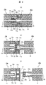
- FIG. 1 is a schematic configuration diagram of a sterile connector according to a first embodiment of the present invention.
- the first connector 10 and the second connector 20 constituting the sterile connector are connected.
- FIG. 1B shows a state in the middle of pulling out (removing) the second connector 20 from the first connector 10
- the first connector 10 includes a first flow path 11 through which a fluid flows and a first housing 14 at one end.
- the second opening 15 is defined, the first connector end 18 is formed at the other end, and the end of the first flow path 11 is formed (continuously formed), and the inner diameter of the first housing 14 is larger than that of the first housing 14.
- a cylindrical first conduit 13 having a small outer diameter is provided.
- the distal end portion of the first conduit 13 extends along the axial direction of the first connector 10 by a predetermined distance from the end of the first housing 14 that defines the second opening 15. 10 axially inside. Further, the distal end portion of the first conduit 13 is opened to form a first opening 12, and the first opening 12 communicates with the first flow path 11.
- a first concave portion 16 that is a space having a concave shape in the longitudinal section is formed by the outer peripheral surface of the first duct 13 and the inner peripheral surface of the first housing 14. In other words, from the end of the first housing 14 that defines the second opening 15, the first connector 10 extends into the cylindrical space that continues to the inside along the axial direction of the first connector 10.
- a first pipe line 13 having an outer diameter smaller than the inner diameter of the housing 14 has a first flow path 11 therein and is formed in a convex shape in a vertical cross section so as to protrude toward the second opening 15 side. ing.
- a disc-shaped first sealing member 17 is provided at the end of the first housing 14 that defines the second opening 15 so as to close the second opening 15.
- the disc-shaped first sealing member 17 has an outer peripheral surface fixed to the inner peripheral surface of the first housing 14 and has a single first slit 17A at a substantially central portion.
- the second connector 20 has a cylindrical second housing 25, a second flow path 21 through which fluid flows, and a third opening defined by the second housing 25 at one end. 22 and a second connector end 26 at the other end.
- the inside of the second housing 25 that continues from the end of the second housing 25 that defines the third opening 22 to the tip of the second flow path 21 along the axial direction of the second connector 20.
- the inner diameter of the second housing 25 that defines the second recess 24 is larger than the diameter of the second flow path 21, and the diameter of the first flow path 11 is substantially equal to the diameter of the second flow path 21. .
- a disc-shaped second sealing member 23 is provided at the end of the second housing 25 that defines the third opening 22 so as to close the third opening 22.
- the disc-shaped second sealing member 23 has an outer peripheral surface fixed to the inner peripheral surface of the second housing 25 and has a second slit 23 ⁇ / b> A at a substantially central portion.
- the outer peripheral surface of the first sealing member 17 and the inner peripheral surface of the first housing 14 are fixed, and the outer peripheral surface of the second sealing member 23 and the inner peripheral surface of the second housing 25 are Is fixed by, for example, bonding with an adhesive or heat welding.
- an adhesion method that does not affect the cells such as using an adhesive having no cytotoxicity, is desirable.
- the outer diameter of the first conduit 13 of the first connector 10 is smaller than the inner diameter of the end of the second housing 25 that defines the third opening 22 of the second connector 20. Further, the outer diameter of the second housing 25 of the second connector 20 is smaller than the inner diameter of the first housing 14 that defines the second opening 15 of the first connector 10.
- the first sealing member 17 and the second sealing member 23 are preferably made of a material that has elasticity, excellent adhesion, and can be sterilized.
- an elastic body such as rubber is preferable. is there.
- the members constituting the first flow path 11 and the second flow path 21, that is, the first housing 14 and the second housing 25 are not toxic to cells such as polycarbonate, polystyrene, polypropylene, and the like. It is desirable to form with plastic which has both plasticity and rigidity. Instead of plastic, it may be formed of a metal that is not toxic to cells.
- 1A is a vertical cross-sectional view in a state where the first connector 10 and the second connector 20 are connected or fitted, and the right view is a cross-sectional view taken along the line AA. Either one of the first connector 10 and the second connector 20 is pushed into the other side to be connected or fitted.
- first connector 10 is fixed and the second connector 20 is moved will be described as an example.
- the second outer surface defining the first conduit 13 constituting the first connector 10 and the second opening 22 of the second connector 20 are defined.
- a gap with the inner peripheral surface of the housing 25 is sealed with a second sealing member 23.
- the gap between the outer peripheral surface of the second housing 25 of the second connector 20 and the inner peripheral surface of the first housing 14 that defines the second opening 15 of the first connector 10 is the first gap. It is sealed with a sealing member 17.
- the first flow path 11 and the second flow path 21 communicate with each other through the second recess 24.
- the housing 25, the first sealing member 17, and the first housing 14 are arranged, and hermeticity is established by the first sealing member 17 and the second sealing member 23. That is, the first flow path 11 and the second flow path 21 can be communicated while maintaining a closed system.
- the distal end portion of the second housing 25 is inserted into the first connector 10 through the first slit 17A provided in the substantially central portion of the first sealing member 17 as described above. Accordingly, the first sealing member 17 is pushed into the inner peripheral surface side of the first housing 14.
- the second sealing member 23 is connected to the second housing by the distal end portion of the first pipe line 13 through a single second slit 23A provided in the approximate center of the second sealing member 23. By being pushed into the inner peripheral surface side of 25.
- the second connector 20 When the second connector 20 is moved to the right from the connection or fitting state shown in FIG. 1A, the second connector 20 is moved from the first connector 10 shown in FIG. It will be in the state of being pulled out (removed). As shown in the left diagram of FIG. 1B, the end of the second housing 25 that defines the third opening 22 is more than the tip of the first conduit 13, that is, the first opening 12. They are separated by moving in the right direction toward the page. At this time, when the first conduit 13 that has pushed the second sealing member 23 toward the inner peripheral surface of the second housing is detached from the end of the second housing 25, for example, rubber or the like The 2nd sealing member 23 formed with an elastic body will be in the state which seals the 3rd opening part 22 with an own elastic force.
- the distal end portion of the second housing 25 that defines the third opening 22 is still located inside the first housing 14 that defines the second opening 15.
- the gap between the outer peripheral surface of the second housing 25 and the inner peripheral surface of the first housing 14 is maintained in a state of being sealed by the first sealing member 17.
- the second housing 25, the first sealing member 17 and the first sealing member 23 are arranged concentrically in the radial direction around the center of the second sealing member 23.
- the second channel 21 is sealed (closed) by being arranged with the housing 14 and sealing the third opening 22 by the second sealing member 23.
- the second slit 23A is not shown, but this is because the third opening 22 is automatically formed by the elastic force of the second sealing member 23 as described above. At this time, the second slit 23A through which the first pipe 13 has been inserted until then is closed by the elastic force, and is not shown.
- FIG. 1C shows a state after the second connector 20 is pulled out from the first connector 10.
- the end of the second housing 25 that defines the third opening 22 becomes the second It is spaced apart from the end of the first housing 14 that defines the opening 15.
- the end of the first housing 14 that defines the second opening 15 has pushed the first sealing member 17 into the inner peripheral surface of the first housing 14 until then. Leave from 25.
- gum will be in the state which seals the 2nd opening part 15 with an own elastic force, for example.
- the first slit 17A is closed by an elastic force.
- the 1st connector 10 and the 2nd connector 20 can be removed by the 1st sealing member 17 and the 2nd sealing member 23, respectively, maintaining a closed system.
- the first connector 10 having the first flow path 11 and the second connector 20 having the second flow path 21 can be removed while maintaining a closed system.
- a possible aseptic connector can be realized.
- FIG. 2 is a vertical cross-sectional view of the aseptic connector of Example 2 according to another example of the present invention.
- 2A shows a state in which the first connector and the second connector are connected
- FIG. 2B shows a state in the middle of pulling out the second connector from the first connector.
- c) shows a state after the second connector is pulled out from the first connector.
- the 1st sealing member 17 and the 2nd sealing member 23 were directly fixed to the inner peripheral surface of the 1st housing 14 and the 2nd housing 25 by adhesion
- the first and second housings are provided with a structure for holding these sealing members, and the shape of the sealing member is different from that of the first embodiment.
- the same components as those in FIG. 1 are denoted by the same reference numerals, and description thereof is omitted below.
- the first sealing member 17a has a substantially H-shaped longitudinal section, and the outer edge of the disc-shaped portion on the first conduit 13a side is divided into two.
- the first housings 14a and 14b thus formed are sandwiched and fixed.
- the first housings 14a and 14b divided into two parts are bonded or thermally welded to each other on the outer peripheral side.
- the 1st pipe line 13a has the shape where the outer diameter expands to the left side from the 1st opening part 12 along the axial direction of the 1st connector 10a. That is, the outer peripheral surface of the first conduit 13 is inclined like a conical side surface.
- the second sealing member 23a has a substantially H-shaped vertical cross section, and the outer edge portion of the disk-like portion on the second flow path 21 side is sandwiched between the second housings 25a and 25b divided into two. And fixed.
- the two divided second housings 25a and 25b are bonded or thermally welded to each other on the outer peripheral side.
- the second recess 24 defined by the inner peripheral surface of the divided second housing 25a is directed from the second sealing member 23a side to the tip end portion of the second flow path 21, and is divided. The diameter of the inner peripheral surface of the housing 25a is reduced.
- the 2nd which connects the 1st flow path 11 and the 2nd flow path 21.
- the diameter of the recess 24, that is, the inner diameter of the second housing 25 a can be made closer to the flow path diameters of the first flow path 11 and the second flow path 21.
- the area where the channel rapidly expands is reduced.
- the channel resistance in the first channel 11 and the second channel 21 communicated with each other can be made uniform as compared with the first embodiment.
- the second housing 25a divided into two includes a region containing the second recess 24 and a region containing the second flow path 21.
- the outer diameter of the region including the second recess 24 is smaller than the outer diameter of the region including the second flow path 21, and the second housing 25 a includes the second recess 24 and the second flow path 21.
- a step portion is provided at a position corresponding to the connecting portion.
- the gap between the outer peripheral surface of the first conduit 13a and the inner peripheral surfaces of the second housings 25a and 25b is sealed by the second sealing member 23a. Is done.
- the gap between the outer peripheral surfaces of the second housings 25a and 25b divided into two and the inner peripheral surface of the first housing 14 is sealed by the first sealing member 17a.
- the disc-shaped portion on the second opening 15 side of the first sealing member 17a is inserted into the second housing 25a containing the second recess 22 through the first slit 17A. Elastically deforms and increases its thickness.
- the disc-shaped portion on the second opening 15 side of the first sealing member 17a is in close contact with the step portion of the second housing 25a, so that the first connector 10a and the second connector 20a
- the airtightness can be improved as compared with the first embodiment.
- the third opening 22 of the second connector 20a is automatically sealed by the elastic force of the second sealing member 23 itself.
- the second opening 15 of the first connector 10a is automatically sealed by the elastic force of the first sealing member 17 itself.
- FIG. 3 is an external view of the sterile connector shown in FIG. 2
- FIG. 3 (a) is an external view of the first sealing member 17
- FIG. 3 (b) is an external view of the first and second connectors.
- FIG. 3C is an exploded perspective view of the first and second connectors.
- the above-described first sealing member 17a having a substantially H-shaped longitudinal section is composed of two disk-shaped portions having different diameters and a connecting portion for connecting them, and the first sealing member 17a The slit 17A is formed so as to penetrate the two disk-shaped portions and the connection portion connecting them.
- FIGS. 3B and 3C the first sealing member 17a described above is assembled so as to be sandwiched between the first housings 14a and 14b divided into two.
- the second sealing member 23a is assembled so as to be sandwiched between the second housings 25a and 25b divided into two.
- the first housings 14 a and 14 b divided into two are bonded or thermally welded to each other on the outer peripheral side, but the following configuration may be used instead.
- it has the surface which supports the outer peripheral part of the inner peripheral surface of the 1st housing 14b divided into 2 parts shown in FIG.3 (c), and the small diameter disc-shaped part which comprises the 1st sealing member 17a.
- a male screw and a female screw are respectively formed on the outer peripheral surface of the convex and cylindrical first housing 14a, and the first housings 14a and 14b are screwed together.
- the second housings 25a and 25b divided into two may be screwed together.
- an adhesive having no cytotoxicity may be applied to the screw portions and then screwed.
- the outer peripheral surface of the first pipe line 13 has an inclination so that the resistance when inserting the second slit 23A of the second sealing member 23a. Can be reduced.
- the channel resistances in the first channel 11 and the second channel 21 communicated with each other can be made uniform as compared with the first embodiment.
- FIG. 4 is a longitudinal sectional view of the aseptic connector of Example 3 according to another embodiment of the present invention, and FIG. 4 (a) shows a state in which the first connector and the second connector are connected. 4 (b) shows a state in the middle of pulling out the second connector from the first connector, and FIG. 4 (c) shows a state after the second connector is pulled out from the first connector.
- the first pipe line 13a constituting the first connector 10a of the second embodiment is formed in a needle shape
- the shape of the second connector 20 shown in the first embodiment is the second connector.
- the second embodiment is different from the first and second embodiments in that the outer diameter of the second housing is different between the region containing the second recess 24 and the region containing the second flow path.
- the same components as those in the first embodiment or the second embodiment are denoted by the same reference numerals, and the description thereof is omitted below.
- the configuration in which the connector is removed without applying pressure is the first configuration shown in FIG.
- the present invention is not limited to the configuration of the connector 10b and the second connector 20b, but can be similarly applied to the structure of the sterile connector of the first embodiment described above, that is, the configuration of the first connector 10 and the second connector 20 shown in FIG. . Further, the present invention can be similarly applied to the structure of the sterile connector according to the second embodiment described above, that is, the configuration of the first connector 10a and the second connector 20a shown in FIG.
- the liquid in the first flow path 11 is set to a negative pressure, that is, the first flow path is equivalently brought into the suction state, so that the first concave portion is removed from the needle-like first conduit 13b.
- the liquid can be prevented from leaking into the 16 spaces.
- an elastic tube (not shown) is connected to each of the first connector end 18 of the first connector 10b and the second connector end 26 of the second connector 20b, a pinch valve is connected to one elastic tube, and the other Connect the iron pump to the elastic tube. In the connection state shown in FIG. 4A, the pinch valve is closed, and the ironing pump is driven so that the liquid flows from the second channel 21 to the first channel 11.
- the second connector 20b is connected to the first connector as shown in FIGS. 4B and 4C. If it removes from 10b, it can prevent that a liquid leaks from the 1st opening part 12 of the 1st flow path 11.
- FIG. 1st connector 10b and the 2nd connector 20b which are shown in FIG. 4, but the 1st shown in the above-mentioned FIG.
- the present invention can be similarly applied to the configurations of the connector 10 and the second connector 20, and the first connector 10a and the second connector 20a shown in FIG.
- the sealing property (closing property) of the second connector 20b can be further improved.
- FIG. 5 shows a longitudinal sectional view of the first connector of Example 4 according to another example of the present invention.
- the present embodiment is different from the first embodiment in that a mechanism is provided for setting a positive pressure in the space of the first recess 16 in the first connector 10 shown in the first embodiment.
- Constituent elements similar to those of the first embodiment are denoted by the same reference numerals, and redundant description is omitted below.
- the first connector 10 c has one end communicating with the first recess 16 and the other end closed to form a closed space integrally with the first recess 16 and the volume of the closed space.
- the variable protrusion 14c has, for example, a bellows structure.
- the volume of the closed space formed integrally with the first recess 16 is reduced, and the space in the first recess 16 is made positive.
- the volume of the closed space formed integrally with the first recess 16 is expanded, and the inside of the space of the first recess 16 is set to a negative pressure.
- variable projection 14c When the variable projection 14c is pressed in a state where the first connector 10c is connected to the second connector 20 shown in FIG. 1, for example, the pressure in the space of the first recess 16 becomes positive.
- the liquid When the first connector 10c is pulled out from the second connector 20 while maintaining this state, the liquid is first introduced into the first flow path 11 from the first conduit 13 constituting the first connector 10c. It does not leak into the space of the recess 16 of the above. Therefore, the liquid is prevented from adhering to the outer surfaces of the second sealing member 23 constituting the second connector 20 and the end of the second housing 25 (the end defining the third opening 22). it can.
- the second connector is the second connector 20 of the first embodiment.
- the present invention is not limited to this, and the structure of the second connector 20a shown in FIG. 2 or the second connector 20b shown in FIG. Also good.
- it replaces with the 1st sealing member 17 and the 1st pipe line 13 which comprise the 1st connector 10c, and the 1st pipe line 13a and the 1st sealing member 17a which are shown in FIG. 2, or FIG.
- the variable protrusion 14c may be a structure that can be integrated with the first recess 16 to form a closed space.
- variable projection 14c a port capable of communicating with the first recess 16 is provided in the first housing 14, the pump and the port are connected by an elastic tube or the like, and the space of the first recess 16 is in a positive pressure state. It may be configured so that
- the first conduit in the first flow path is formed in the first flow path. It becomes possible to prevent liquid leakage.
- FIG. 6 shows an overall schematic configuration diagram of the cell culture device of Example 5 according to another example of the present invention.
- the cell culture apparatus 1 includes a cell culture container 31, a supply bag 32 containing a medium such as a cell culture solution, a recovery bag 33 that collects a medium such as a cell culture solution after use, and a flow.
- a path switching member 38 is provided.
- the cell culture container 31 is connected to the supply bag 32 and the collection bag 33 through a flow path.
- FIG. 6 shows an example in which four cell culture containers 31 are arranged, the present invention is not limited to this, and a desired number of cell culture containers 31 may be arranged.
- the cell culture apparatus 1 has one end connected to the supply back 32 and the other end connected to the upstream branch flow path 35 (upstream branch flow path connected to each cell culture vessel 31).
- the flow path 34 one end connected to the recovery bag 33, the other end connected to the flow path switching member 38, the downstream common flow path 37, and the downstream side connecting the flow path switching member 38 and each cell culture vessel 31
- a branch channel 36 (a downstream branch channel connected to each cell culture vessel 31) is provided.
- the cell culture apparatus 1 Since the cell culture apparatus 1 is a closed culture system, it is necessary to apply the driving force of a liquid such as a cell culture medium as a medium from outside the closed culture system. Therefore, a peristaltic pump 39 that permeates the elastic tube from the outside is disposed in the upstream common flow path 34. Therefore, at least a part of the upstream common channel 34 needs to be a channel having elasticity.
- the liquid such as the intracellular solution in the upstream common flow path 34 is pressurized and flows in the upstream common flow path 34 toward the cell culture container 31 side. That is, a positive pressure is generated in the flow path.
- the peristaltic pump 39 may be disposed in the downstream common flow path 37.
- the downstream common flow path 37 has a negative pressure, and a liquid such as a cell culture solution that is a medium is sucked out from the supply bag 32.
- the two squeezing pumps 39 arranged in the upstream common channel 34 and the downstream common channel 37 can reduce the pressure load on the liquid such as the cell culture fluid flowing in the channel.
- the liquid such as the cell culture solution in the supply bag 32 is sent to the cell culture container 31 through the upstream common channel 34 and the upstream branch channel 35.
- the flow is switched to the cell culture container 31 connected to the downstream common flow path 37 by the switching operation of the flow path switching member 38.
- the used cell culture liquid or the like that has remained in the cell culture container 31 until then is pushed out by the inflowing liquid such as the cell culture liquid, and the downstream branch flow path 36 and the flow path switching member 38. And it is sent to the collection bag 33 through the downstream common channel 37.
- FIG. 7 shows an integrated flow path member as an integrated member that combines the upstream and downstream common flow paths, the upstream and downstream branch flow paths, and the flow path switching member that constitute the cell culture apparatus shown in FIG.
- the external perspective view of this integrated flow path member and the cell culture container is shown.
- the cell culture vessel 41 includes a culture surface 41a, an inflow channel 41b and a discharge channel 41c described later.
- the integrated flow path member 42 includes a flow path switching member 43 and is configured to be connectable to the four cell culture containers 41.
- FIG. 8 is a longitudinal sectional view of the cell culture container and the accumulation channel member shown in FIG.
- the cell culture vessel 41 includes a culture surface 41a, an inflow channel 41b, and an exhaust channel 41c.
- the inflow channel 41b communicates with the culture surface 41a at an inlet 41e, and the exhaust channel 41c It communicates with the culture surface 41a at the outlet 41f.
- the integrated flow path member 42 includes an inlet 42a, an upstream common flow path 42b, an upstream branch flow path 42c, a downstream branch flow path 42d, a storage chamber 42e of the flow path switching member 43, and a downstream common flow path on the upper surface.
- a path 42f and a discharge port 42g are provided.
- the cell culture container 41 and the accumulation channel member 42 have a connection port 41d and a port 42h, respectively, so that they can be connected to each other.
- the integrated flow path member 42 includes a plurality of ports 42h that can be connected to a plurality of cell culture vessels 41.
- the cell culture vessel 41 and the collecting flow path member 42 are made of a plastic that is not toxic to cells such as polycarbonate, polystyrene, polypropylene, and has rigidity together with plasticity.
- An inflow channel 41b and an exhaust channel 41d are connected to the connection port 41d of the cell culture container 41.
- the inflow channel 41b and the exhaust channel 41d are connected to the connection port 41d on one side surface of the cell culture container 41. It is connected.
- the upstream branch flow path 42b and the downstream branch flow path 42d are connected to the port 42h of the integrated flow path member 42.
- the upstream branch flow path 42c and the downstream branch flow path 42d are connected to each of the integrated flow path members 42. It is connected with the port 42h up and down on the side.
- the upstream branch channel 42c and the inflow channel 41b of the cell culture container 41, the downstream branch channel 42d and the discharge channel 41c of the cell culture container 41 are used. Are configured to communicate with each other.
- the inlet channel 41b and the outlet channel 41d are connected to the connection port 41d on the same side surface of the cell culture container 41, and the upstream branch channel 42b and the downstream branch channel 42d are integrated flow. Since the structure is connected to the port 42 on each side surface of the path member 42, the cell culture container 41 can be attached to and detached from the integrated flow path member 42 from one direction, so that the attachment / detachment operation is facilitated.
- FIG. 9 is an enlarged view of the region B shown in FIG. 8, and is a partially enlarged view of a connection portion between the cell culture container 41 and the accumulation channel member 42.
- the second connector 20 shown in FIG. 1 is provided on the same side surface where the inflow channel 41b and the exhaust channel 41c of the cell culture vessel 41 are arranged, respectively. And it is provided up and down so as to be continuous with the discharge channel 41c.
- the first connector 10 shown in FIG. 1 is connected to the upstream branch flow path 42c and the downstream branch flow path 42d of the integrated flow path member 42 on the same side surface where the upstream branch flow path 42c and the downstream branch flow path 42d are arranged, respectively.
- the inflow channel 41b of the cell culture device 41 communicates with the upstream branch channel 42c of the integrated channel member 42 through the space of the second recess 24 of the second connector 20 while maintaining a closed system. Is done.
- the discharge channel 41 c of the cell culture device 41 maintains a closed system with the lower branch channel 42 d of the integrated channel member 42 through the space of the second recess 24 of the second connector 20. While communicating.
- the second sealing member 23 is caused by its own elastic force.
- the third opening 22 of the second connector 20 is closed.
- the inflow channel 41b and the discharge channel 41c of the cell culture container 41 are sealed.
- the first sealing member 17 closes the second opening 15 of the first connector 10 by its own elastic force.
- the upstream branch flow path 42c and the downstream branch flow path 42d of the integrated flow path member 42 are sealed.
- a configuration in which the first connector 10 illustrated in FIG. 1 is provided in the integrated flow path member 42 and the second connector 20 is provided in the cell culture container 41 is not limited thereto.
- One connector 10 may be provided in the cell culture container 41 and the second connector 10 may be provided in the accumulation channel member 42.
- the first connector 10a and the second connector 20a of the second embodiment may be used, and further, the aseptic connector shown in the third or fourth embodiment may be used.
- FIG. 10 is a vertical cross-sectional view of the integrated flow path member 42 shown in FIG.
- the flow path switching member 43 disposed in the storage chamber 42e includes a downstream branch flow path 42d communicating with the discharge flow path 41c of the desired culture vessel 41, a downstream common flow path 42f, and the like.
- a connection flow path is provided inside.
- a plurality of permanent magnets 50 are embedded without interfering with this connection flow path and spaced apart from each other in an annular shape.
- a plurality of electromagnets 51 made of a magnetic material with a coil wound are separated from each other and embedded in the integrated flow path member 42 at a position facing the permanent magnets 50 outside the storage chamber 42e. Yes.
- the flow path switching member 43 is rotated, so that the connection flow path is positioned at a position facing the desired downstream branch flow path 42d.
- the conducting wire for energizing the coil is routed to the outside of the closed cell culture device 1.
- the rotational axis of the flow path switching member 43 substantially coincides with the central axis of the lower common flow path 42f of the integrated flow path member 42.
- the drive mechanism of the flow path switching member 43 is not limited to the configuration including the permanent magnet 50 and the electromagnet 51 described above.
- the flow path switching member 43 extends so as to protrude from below the integrated flow path member 42 (the lower common flow path 42f side), and a rotational driving force is applied to the protruding portion by, for example, a stepping motor or a servo motor. It may be configured to transmit. In this case, in order to maintain a closed system, it is necessary to cover the periphery of the protrusion with, for example, a film-shaped sealing member.
- FIG. 11 is a partial vertical cross-sectional view of the connection portion between the cell culture container 41 and the accumulation channel member 42 shown in FIG. 8, and shows the structure of the fixing portion.
- FIG. 11 shows, as an example, a configuration in which the first connector 10a of Example 2 shown in FIG. 2 is provided so that the inflow channel 41b of the cell culture container 41 is continuous with the first channel.
- 2 shows a configuration in which the second connector 20a shown in FIG. 2 is provided so that the upper branch flow path 42c of the integrated flow path member 42 is continuous with the second flow path 21.
- the outer peripheral surface of the region containing the second flow path 21 (the upstream branch flow path 42c in FIG. 11) is divided into two parts.
- the 2nd connector 20a has the convex structure 52 formed in the annular
- the first connector 10a (connector including the inflow channel 41b of the cell culture container 41) is an annular shape at the outer peripheral surface of the first housing 14a and does not interfere with the first sealing member 17a.
- the concave structure 53 is provided. When the cell culture container 41 and the accumulation channel member 42 are connected, the concave structure 53 and the convex structure 52 are engaged with each other, thereby forming a snap-fit structure and preventing the cell culture container 41 from unintentionally falling off.
- the discharge channel 41c of the cell culture container 41 and the downstream branch channel 42d of the integrated channel member 42 have the same configuration as described above.
- FIG. 11 illustrates the case where the first connector 10a and the second connector 20b of the second embodiment shown in FIG. 2 are used as the first connector and the second connector constituting the aseptic connector.
- the sterile connector of Example 1 shown in FIG. 1 the sterile connector of Example 3 shown in FIG. 4, or the sterile connector of Example 4 shown in FIG. 5 may be used as the sterile connector.
- FIG. 12 is a view showing a modification of the cell culture container and the accumulation channel member constituting the cell culture apparatus shown in FIG. 7,
- FIG. 12 (a) is a top view of the cell culture container, and
- FIG. It is an external appearance perspective view of a cell culture container and an accumulation channel member. 7 and 8 described above, the inflow channel 41b and the exhaust channel 41c in the cell culture container 41 are arranged vertically with respect to the culture surface 41a, and the upstream branch channel 42c of the integrated channel member 42 and The downstream branch flow path 42d is arranged vertically within the same side surface.
- the inflow channel 41b and the exhaust channel 41c in the cell culture container 41 are arranged vertically with respect to the culture surface 41a, and the upstream branch channel 42c of the integrated channel member 42 and The downstream branch flow path 42d is arranged vertically within the same side surface.
- the culture surface 41a communicates with the culture surface 41a at two locations on the diagonal line of the culture surface 41a on the bottom surface side of the cylindrical culture surface 41a, and has a circular cross section.
- An inflow channel 41b and a discharge channel 41c extending in parallel to the tangential direction of the surface 41a in the same horizontal plane are provided. Thereby, the inflow channel 41b and the exhaust channel 41c are connected to the connection port 41d in the horizontal direction on the same side surface of the cell culture container 41.
- the integrated flow path member 42 has the entire side surface (only one side is illustrated in FIG. 12B) as a whole, for example, a sealing member 54 made of an elastic body such as rubber.
- the slits 55 are respectively provided at positions that are opposite to the inlet channel 41b and the outlet channel 41c of the cell culture container 41 and that can be inserted.
- a connector continuous with the upstream branch flow path 42b is located at the position of each slit 55, that is, the slit 55 facing the inflow flow path 41b. It is arranged in.
- a connector continuous with the downstream branch flow path 42d is disposed in the integrated flow path member 42 at the position of the slit 55 facing the discharge flow path 41c.
- a number of parts can be reduced compared with the structure shown in FIG. That is, in FIG. 9, two sealing members are arranged on each side surface of the integrated flow path member 42, but in the configuration shown in FIG. 12C, one sealing member is arranged on one side surface. Can be halved.
- the slits 55 may be formed in accordance with the number of flow paths connected to each other, and three slits 55 or four slits 55 may be formed on the same side surface of the integrated flow path member 42.
- the flow path switching member 43 has a connection flow path that can connect the downstream common flow path 42f and the downstream branch flow path 42d.
- the present invention is not limited to this.
- a configuration having a connection channel that enables connection between the upstream common channel 42 b and the upstream branch channel 42 c and a configuration in which the connection channel is arranged in the upper part of the integrated channel member 42 may be adopted.
- this invention is not limited to the above-mentioned Example, Various modifications are included.
- the above-described embodiments have been described in detail for easy understanding of the present invention, and are not necessarily limited to those having all the configurations described.
- a part of the configuration of one embodiment can be replaced with the configuration of another embodiment, and the configuration of another embodiment can be added to the configuration of one embodiment.
- SYMBOLS 1 Cell culture apparatus, 10, 10a, 10b ... 1st connector, 11 ... 1st flow path, 12 ... 1st opening part, 13, 13a, 13b ... 1st pipe line, 14, 14a, 14b ... 1st housing, 14c ... Variable projection part, 15 ... 2nd opening part, 16 ... 1st recessed part, 17, 17a, ... 1st sealing member, 17A ... 1st slit, 18 ... 1st Connector end, 20, 20a ... second connector, 21 ... second flow path, 22 ... third opening, 23, 23a, 23b ... second sealing member, 23A ... second slit, 24 ...
Landscapes
- Health & Medical Sciences (AREA)
- Life Sciences & Earth Sciences (AREA)
- Organic Chemistry (AREA)
- Engineering & Computer Science (AREA)
- Bioinformatics & Cheminformatics (AREA)
- Chemical & Material Sciences (AREA)
- Zoology (AREA)
- Wood Science & Technology (AREA)
- Sustainable Development (AREA)
- Microbiology (AREA)
- Biotechnology (AREA)
- Biomedical Technology (AREA)
- Biochemistry (AREA)
- General Engineering & Computer Science (AREA)
- General Health & Medical Sciences (AREA)
- Genetics & Genomics (AREA)
- Clinical Laboratory Science (AREA)
- Molecular Biology (AREA)
- Apparatus Associated With Microorganisms And Enzymes (AREA)
Abstract
Cette invention concerne un connecteur stérile constitué d'un premier connecteur 10 qui comprend : un premier boîtier 14 comportant un premier canal d'écoulement 11 pour faire s'écouler un fluide ; une première canalisation 13 reliée au premier canal d'écoulement 11 ; une première ouverture 12 et une deuxième ouverture 14, ladite première ouverture 12 étant positionnée vers l'intérieur par rapport à la deuxième ouverture 15 dans le sens axial du premier boîtier 14 ; et un premier élément d'étanchéité 17 couvrant la deuxième ouverture 15. Le connecteur stérile est en outre constitué d'un second connecteur qui comprend : un second boîtier 25 comportant un second canal d'écoulement 21 pour faire s'écouler un fluide ; une troisième ouverture 22 ; et un second élément d'étanchéité recouvrant la troisième ouverture 22. Les premier et second connecteurs 10 et 20 peuvent être détachés l'un de l'autre. Le premier élément d'étanchéité 17 scelle un espace entre la surface circonférentielle intérieure du premier boîtier 14 et la surface circonférentielle extérieure du second boîtier 25, tandis que le second élément d'étanchéité 23 scelle un espace entre la surface circonférentielle intérieure du second boîtier 25 et la surface circonférentielle extérieure de la première canalisation 13 de façon que le premier canal d'écoulement 11 soit en communication avec le second canal d'écoulement 21.
Priority Applications (4)
| Application Number | Priority Date | Filing Date | Title |
|---|---|---|---|
| JP2016557418A JPWO2016072009A1 (ja) | 2014-11-07 | 2014-11-07 | 無菌コネクタ及びそれを有する細胞培養装置 |
| US15/521,348 US20190153377A1 (en) | 2014-11-07 | 2014-11-07 | Sterile connector and cell culture device provided therewith |
| CN201480083175.1A CN107075442A (zh) | 2014-11-07 | 2014-11-07 | 无菌连接器及具有该无菌连接器的细胞培养装置 |
| PCT/JP2014/079537 WO2016072009A1 (fr) | 2014-11-07 | 2014-11-07 | Connecteur stérile et dispositif de culture cellulaire l'utilisant |
Applications Claiming Priority (1)
| Application Number | Priority Date | Filing Date | Title |
|---|---|---|---|
| PCT/JP2014/079537 WO2016072009A1 (fr) | 2014-11-07 | 2014-11-07 | Connecteur stérile et dispositif de culture cellulaire l'utilisant |
Publications (1)
| Publication Number | Publication Date |
|---|---|
| WO2016072009A1 true WO2016072009A1 (fr) | 2016-05-12 |
Family
ID=55908761
Family Applications (1)
| Application Number | Title | Priority Date | Filing Date |
|---|---|---|---|
| PCT/JP2014/079537 WO2016072009A1 (fr) | 2014-11-07 | 2014-11-07 | Connecteur stérile et dispositif de culture cellulaire l'utilisant |
Country Status (4)
| Country | Link |
|---|---|
| US (1) | US20190153377A1 (fr) |
| JP (1) | JPWO2016072009A1 (fr) |
| CN (1) | CN107075442A (fr) |
| WO (1) | WO2016072009A1 (fr) |
Families Citing this family (2)
| Publication number | Priority date | Publication date | Assignee | Title |
|---|---|---|---|---|
| US10431926B2 (en) * | 2015-04-14 | 2019-10-01 | Hewlett Packard Enterprise Development Lp | Magnetic fluid connector |
| CN118460373B (zh) * | 2024-07-11 | 2024-10-15 | 中国科学院苏州生物医学工程技术研究所 | 一种拆组式类器官芯片以及类器官芯片拆组方法 |
Citations (6)
| Publication number | Priority date | Publication date | Assignee | Title |
|---|---|---|---|---|
| US4334551A (en) * | 1979-04-30 | 1982-06-15 | Becton Dickinson & Company | Connector |
| JPH0380191U (fr) * | 1989-12-07 | 1991-08-16 | ||
| JP2000033124A (ja) * | 1998-06-26 | 2000-02-02 | Fresenius Medical Care Deutsche Gmbh | シ―ル部品を備えたコネクタ要素 |
| JP2002515311A (ja) * | 1998-05-20 | 2002-05-28 | バクスター・インターナショナル・インコーポレイテッド | ニードルレスコネクタ |
| JP2008000331A (ja) * | 2006-06-22 | 2008-01-10 | Jms Co Ltd | 連通用ロックコネクタ |
| WO2013002320A1 (fr) * | 2011-06-30 | 2013-01-03 | テルモ株式会社 | Ensemble de connexion et connecteur mâle |
Family Cites Families (8)
| Publication number | Priority date | Publication date | Assignee | Title |
|---|---|---|---|---|
| NL8300386A (nl) * | 1983-02-02 | 1984-09-03 | Steritech Bv | Inrichting voor het steriel met elkaar in verbinding stellen van twee kamers. |
| CN2178118Y (zh) * | 1993-08-21 | 1994-09-28 | 江苏省人民医院 | 持续负压引流器 |
| US7914502B2 (en) * | 2003-07-31 | 2011-03-29 | Nypro Inc. | Anti-drawback medical valve |
| JP4563782B2 (ja) * | 2004-11-26 | 2010-10-13 | 株式会社日立製作所 | 培養装置 |
| JP4403169B2 (ja) * | 2006-12-15 | 2010-01-20 | 株式会社日立製作所 | 細胞培養装置及びその制御方法 |
| US8251346B2 (en) * | 2008-03-04 | 2012-08-28 | Infusion Innovations, Inc. | Devices, assemblies, and methods for controlling fluid flow |
| CN102215903B (zh) * | 2008-03-25 | 2014-08-06 | 美国圣戈班性能塑料公司 | 连接器组件 |
| CN104203337B (zh) * | 2012-02-15 | 2017-06-30 | 可得制品公司 | 无菌性联结装置 |
-
2014
- 2014-11-07 WO PCT/JP2014/079537 patent/WO2016072009A1/fr active Application Filing
- 2014-11-07 JP JP2016557418A patent/JPWO2016072009A1/ja active Pending
- 2014-11-07 US US15/521,348 patent/US20190153377A1/en not_active Abandoned
- 2014-11-07 CN CN201480083175.1A patent/CN107075442A/zh active Pending
Patent Citations (6)
| Publication number | Priority date | Publication date | Assignee | Title |
|---|---|---|---|---|
| US4334551A (en) * | 1979-04-30 | 1982-06-15 | Becton Dickinson & Company | Connector |
| JPH0380191U (fr) * | 1989-12-07 | 1991-08-16 | ||
| JP2002515311A (ja) * | 1998-05-20 | 2002-05-28 | バクスター・インターナショナル・インコーポレイテッド | ニードルレスコネクタ |
| JP2000033124A (ja) * | 1998-06-26 | 2000-02-02 | Fresenius Medical Care Deutsche Gmbh | シ―ル部品を備えたコネクタ要素 |
| JP2008000331A (ja) * | 2006-06-22 | 2008-01-10 | Jms Co Ltd | 連通用ロックコネクタ |
| WO2013002320A1 (fr) * | 2011-06-30 | 2013-01-03 | テルモ株式会社 | Ensemble de connexion et connecteur mâle |
Also Published As
| Publication number | Publication date |
|---|---|
| US20190153377A1 (en) | 2019-05-23 |
| JPWO2016072009A1 (ja) | 2017-08-03 |
| CN107075442A (zh) | 2017-08-18 |
Similar Documents
| Publication | Publication Date | Title |
|---|---|---|
| US10307583B2 (en) | Aseptic coupling devices | |
| JP2022084727A (ja) | 交互接線流の使い捨て濾過ユニット | |
| JP6163198B2 (ja) | キャップ | |
| EP2941287B1 (fr) | Clapet antiretour à filtre intégré | |
| US9121509B2 (en) | Valve that is normally closed in the free state | |
| US20220186169A1 (en) | Power device of a micro channel for external circulation of a bioreactor | |
| US8973596B2 (en) | Applicator assembly with integral check-valve | |
| JP2007222167A (ja) | 微生物学的試験装置、それを含む試験および培養システム、ならびにそれを使用する方法 | |
| US11873913B2 (en) | Umbrella check valve assembly having retention plate | |
| CA2934996A1 (fr) | Module de membrane a fibre creuse | |
| JP6138940B2 (ja) | 流体処理カセットのためのばね式で開くシート | |
| US20120316576A1 (en) | Dermatome swivel double acting valve | |
| WO2016072009A1 (fr) | Connecteur stérile et dispositif de culture cellulaire l'utilisant | |
| JP6079018B2 (ja) | 生体試料移送装置及び生体試料移送方法 | |
| WO2020003504A1 (fr) | Système de culture par perfusion | |
| JP6219682B2 (ja) | パッキン付き弁、弁ユニット | |
| US10350400B2 (en) | Apparatus and methods for aseptic fluid interconnects | |
| JP3192421U (ja) | 培養容器用アダプタ及びこれを備えた培地供給システム | |
| CN216141554U (zh) | 细胞培养瓶 | |
| CN215799613U (zh) | 培养瓶盖 | |
| JP2005137407A (ja) | 接続具 | |
| US20200188915A1 (en) | Fluid Processing Cassettes Incorporating Micro- And Macrofluidic Channels | |
| JP2015096191A (ja) | 流体処理装置用接続機構およびそれを用いた流体処理システムと流体処理装置の作動方法 | |
| JP2015228801A (ja) | 培地用バルブ及びこれを備えた培地供給システム | |
| CN102716534A (zh) | 点滴注射液自动两次两接触面密封的方法及装置 |
Legal Events
| Date | Code | Title | Description |
|---|---|---|---|
| 121 | Ep: the epo has been informed by wipo that ep was designated in this application |
Ref document number: 14905450 Country of ref document: EP Kind code of ref document: A1 |
|
| ENP | Entry into the national phase |
Ref document number: 2016557418 Country of ref document: JP Kind code of ref document: A |
|
| NENP | Non-entry into the national phase |
Ref country code: DE |
|
| 122 | Ep: pct application non-entry in european phase |
Ref document number: 14905450 Country of ref document: EP Kind code of ref document: A1 |