WO2016072009A1 - Sterile connector and cell culture device provided therewith - Google Patents
Sterile connector and cell culture device provided therewith Download PDFInfo
- Publication number
- WO2016072009A1 WO2016072009A1 PCT/JP2014/079537 JP2014079537W WO2016072009A1 WO 2016072009 A1 WO2016072009 A1 WO 2016072009A1 JP 2014079537 W JP2014079537 W JP 2014079537W WO 2016072009 A1 WO2016072009 A1 WO 2016072009A1
- Authority
- WO
- WIPO (PCT)
- Prior art keywords
- flow path
- housing
- cell culture
- sealing member
- connector
- Prior art date
Links
Images


Classifications
-
- C—CHEMISTRY; METALLURGY
- C12—BIOCHEMISTRY; BEER; SPIRITS; WINE; VINEGAR; MICROBIOLOGY; ENZYMOLOGY; MUTATION OR GENETIC ENGINEERING
- C12M—APPARATUS FOR ENZYMOLOGY OR MICROBIOLOGY; APPARATUS FOR CULTURING MICROORGANISMS FOR PRODUCING BIOMASS, FOR GROWING CELLS OR FOR OBTAINING FERMENTATION OR METABOLIC PRODUCTS, i.e. BIOREACTORS OR FERMENTERS
- C12M37/00—Means for sterilizing, maintaining sterile conditions or avoiding chemical or biological contamination
- C12M37/04—Seals
-
- C—CHEMISTRY; METALLURGY
- C12—BIOCHEMISTRY; BEER; SPIRITS; WINE; VINEGAR; MICROBIOLOGY; ENZYMOLOGY; MUTATION OR GENETIC ENGINEERING
- C12M—APPARATUS FOR ENZYMOLOGY OR MICROBIOLOGY; APPARATUS FOR CULTURING MICROORGANISMS FOR PRODUCING BIOMASS, FOR GROWING CELLS OR FOR OBTAINING FERMENTATION OR METABOLIC PRODUCTS, i.e. BIOREACTORS OR FERMENTERS
- C12M23/00—Constructional details, e.g. recesses, hinges
- C12M23/34—Internal compartments or partitions
-
- C—CHEMISTRY; METALLURGY
- C12—BIOCHEMISTRY; BEER; SPIRITS; WINE; VINEGAR; MICROBIOLOGY; ENZYMOLOGY; MUTATION OR GENETIC ENGINEERING
- C12M—APPARATUS FOR ENZYMOLOGY OR MICROBIOLOGY; APPARATUS FOR CULTURING MICROORGANISMS FOR PRODUCING BIOMASS, FOR GROWING CELLS OR FOR OBTAINING FERMENTATION OR METABOLIC PRODUCTS, i.e. BIOREACTORS OR FERMENTERS
- C12M23/00—Constructional details, e.g. recesses, hinges
- C12M23/38—Caps; Covers; Plugs; Pouring means
-
- C—CHEMISTRY; METALLURGY
- C12—BIOCHEMISTRY; BEER; SPIRITS; WINE; VINEGAR; MICROBIOLOGY; ENZYMOLOGY; MUTATION OR GENETIC ENGINEERING
- C12M—APPARATUS FOR ENZYMOLOGY OR MICROBIOLOGY; APPARATUS FOR CULTURING MICROORGANISMS FOR PRODUCING BIOMASS, FOR GROWING CELLS OR FOR OBTAINING FERMENTATION OR METABOLIC PRODUCTS, i.e. BIOREACTORS OR FERMENTERS
- C12M23/00—Constructional details, e.g. recesses, hinges
- C12M23/44—Multiple separable units; Modules
Definitions
- the present invention relates to a sterile connector and a cell culture apparatus having the same, and more particularly to a sterile connector suitable for aseptically removing a cell culture container from a closed cell culture apparatus and a cell culture apparatus having the same.
- a closed cell culture container In cell culture, in order to prevent external contamination, a closed cell culture container is connected to a closed cell culture container via a tube, and culture is performed in this closed system (closed system).
- a cell culture apparatus is generally used.
- the aseptic connector assembly includes a first connector and a second connector.
- the first connector includes a stem that defines a flow path therein, a first housing that surrounds the stem and defines a first opening, and a first opening.
- the second connector is configured to mate with the first housing and includes a second housing defining the second opening and a second valve disposed on the second opening. When the first housing and the second housing are engaged, the first valve and the second valve are engaged.
- the first valve and the second valve cannot be engaged only by pushing one of the first connector and the second connector to the other side, and the stem in the first connector is moved. Operation is required. If the two-step operation procedure is mistaken, for example, when the first connector is pulled out from the second connector, the first and second valves cannot be sealed, and microorganisms from the outside or There is a risk of invasion of particles containing bacteria. In addition, since two-step operation is required, improvement in workability by the worker cannot be expected.
- the present invention provides a sterile connector capable of easily taking out a desired cell culture vessel from a closed cell culture device while preventing invasion of particles containing microorganisms or bacteria from the outside, and a cell culture device having the same. Is to provide.
- an aseptic connector of the present invention includes (1) a first housing having a first flow path for allowing fluid to flow inside, and a first tube continuous with the first flow path. A first opening in which one end of the first pipe line is released, a second opening defined by an end of the first housing, and the first opening A first connector having a first sealing member disposed on the inner side in the axial direction of the first housing from the second opening and covering the second opening; (2) fluid inside A second housing having a second flow path for flow, a third opening defined by an end of the second housing, and a second sealing member covering the third opening.
- the cell culture device of the present invention is configured such that a cell culture container having an inflow channel through which a liquid required for culture flows and a discharge channel through which liquid after use is discharged, and a plurality of cell culture containers can be connected in parallel.
- the upstream branch channel and the downstream branch channel corresponding to each cell culture vessel, and at least the upstream branch channel to any desired cell culture vessel of the plurality of cell culture vessels
- An integrated flow path member for feeding a liquid required for culture to the inflow flow path via the flow path, and the integrated flow path member is continuous with each of the upstream branch flow path and the downstream branch flow path
- a first housing having a first conduit; a first opening formed by releasing one end of each first conduit; and a second opening defined by an end of the first housing
- a first sealing member that covers the second opening
- the cyst culture container covers a second housing enclosing the inflow channel and the outflow channel, a third opening defined by an end of the second housing, and the third opening.
- a second sealing member, and the first sealing member seals a gap between an inner peripheral surface of the first housing and an outer peripheral surface of the second housing, and the second sealing member.
- the stop member seals the gap between the second housing and the outer peripheral surface of the first conduit, and connects the cell culture container to the accumulation channel member.
- the cell culture container of the present invention is configured such that a cell culture container having an inflow channel through which a liquid required for culture flows and a discharge channel through which liquid after use is discharged can be connected in parallel to a plurality of cell culture containers.
- the upstream branch channel and the downstream branch channel corresponding to each cell culture vessel, and at least the upstream branch channel to any desired cell culture vessel of the plurality of cell culture vessels
- a collecting channel member for sending a liquid required for culture to the inflow channel via the first channel that is continuous with the inflow channel and the discharge channel.
- a second sealing member, and the first sealing member seals a gap between an inner peripheral surface of the first housing and an outer peripheral surface of the second housing, and the second sealing member.
- the stop member seals the gap between the second housing and the outer peripheral surface of the first conduit, and connects the cell culture container to the accumulation channel member.
- a sterile connector capable of easily taking out a desired cell culture container from a closed cell culture apparatus while preventing invasion of particles containing microorganisms or bacteria from the outside, and a cell culture apparatus having the same Can be provided.
- FIG.1 shows the state with which the 1st connector and the 2nd connector were connected
- FIG.1 (b) FIG. 1C shows a state in the middle of pulling out the second connector from the first connector
- FIG. 1C shows a state after the second connector is pulled out from the first connector.
- Fig.2 shows the state with which the 1st connector and the 2nd connector were connected
- FIG.2 (b) Shows a state in the middle of pulling out the second connector from the first connector
- FIG.2 shows the state with which the 1st connector and the 2nd connector were connected
- FIG.2 (b) Shows a state in the middle of pulling out the second connector from the first connector
- FIG. 3A is an external view of the sterile connector shown in FIG. 2
- FIG. 3A is an external view of the sealing member
- FIG. 3B is an external view of the first and second connectors
- FIG. FIG. 6 is an exploded perspective view of the second connector.
- It is a longitudinal cross-sectional view of the aseptic connector of Example 3 which concerns on the other Example of this invention
- Fig.4 (a) shows the state with which the 1st connector and the 2nd connector were connected
- FIG.4 (b) Shows a state in the middle of pulling out the second connector from the first connector
- FIG. 4C shows a state after the second connector is pulled out from the first connector.
- FIG. 7 is an external perspective view of a cell culture container and an accumulation channel member constituting the cell culture device shown in FIG. 6.
- FIG. 8 is a longitudinal sectional view of the cell culture container and the accumulation channel member shown in FIG. 7.
- FIG. 9 is an enlarged view of a region B shown in FIG. It is a longitudinal cross-sectional view of the integrated flow path member shown in FIG. 8, and is an operation explanatory view of the flow path switching member.
- FIG. 8 It is a fragmentary longitudinal cross-sectional view of the connection part of the cell culture container and accumulation flow path member shown in FIG. 8, and is a figure which shows the structure of a fixing part. It is a figure which shows the modification of the cell culture container and accumulation flow path member which comprise the cell culture apparatus shown in FIG. 7, (a) is a top view of a cell culture container, FIG.12 (b) is a cell culture container and It is an external appearance perspective view of an accumulation channel member.
- FIG. 1 is a schematic configuration diagram of a sterile connector according to a first embodiment of the present invention.
- the first connector 10 and the second connector 20 constituting the sterile connector are connected.
- FIG. 1B shows a state in the middle of pulling out (removing) the second connector 20 from the first connector 10
- the first connector 10 includes a first flow path 11 through which a fluid flows and a first housing 14 at one end.
- the second opening 15 is defined, the first connector end 18 is formed at the other end, and the end of the first flow path 11 is formed (continuously formed), and the inner diameter of the first housing 14 is larger than that of the first housing 14.
- a cylindrical first conduit 13 having a small outer diameter is provided.
- the distal end portion of the first conduit 13 extends along the axial direction of the first connector 10 by a predetermined distance from the end of the first housing 14 that defines the second opening 15. 10 axially inside. Further, the distal end portion of the first conduit 13 is opened to form a first opening 12, and the first opening 12 communicates with the first flow path 11.
- a first concave portion 16 that is a space having a concave shape in the longitudinal section is formed by the outer peripheral surface of the first duct 13 and the inner peripheral surface of the first housing 14. In other words, from the end of the first housing 14 that defines the second opening 15, the first connector 10 extends into the cylindrical space that continues to the inside along the axial direction of the first connector 10.
- a first pipe line 13 having an outer diameter smaller than the inner diameter of the housing 14 has a first flow path 11 therein and is formed in a convex shape in a vertical cross section so as to protrude toward the second opening 15 side. ing.
- a disc-shaped first sealing member 17 is provided at the end of the first housing 14 that defines the second opening 15 so as to close the second opening 15.
- the disc-shaped first sealing member 17 has an outer peripheral surface fixed to the inner peripheral surface of the first housing 14 and has a single first slit 17A at a substantially central portion.
- the second connector 20 has a cylindrical second housing 25, a second flow path 21 through which fluid flows, and a third opening defined by the second housing 25 at one end. 22 and a second connector end 26 at the other end.
- the inside of the second housing 25 that continues from the end of the second housing 25 that defines the third opening 22 to the tip of the second flow path 21 along the axial direction of the second connector 20.
- the inner diameter of the second housing 25 that defines the second recess 24 is larger than the diameter of the second flow path 21, and the diameter of the first flow path 11 is substantially equal to the diameter of the second flow path 21. .
- a disc-shaped second sealing member 23 is provided at the end of the second housing 25 that defines the third opening 22 so as to close the third opening 22.
- the disc-shaped second sealing member 23 has an outer peripheral surface fixed to the inner peripheral surface of the second housing 25 and has a second slit 23 ⁇ / b> A at a substantially central portion.
- the outer peripheral surface of the first sealing member 17 and the inner peripheral surface of the first housing 14 are fixed, and the outer peripheral surface of the second sealing member 23 and the inner peripheral surface of the second housing 25 are Is fixed by, for example, bonding with an adhesive or heat welding.
- an adhesion method that does not affect the cells such as using an adhesive having no cytotoxicity, is desirable.
- the outer diameter of the first conduit 13 of the first connector 10 is smaller than the inner diameter of the end of the second housing 25 that defines the third opening 22 of the second connector 20. Further, the outer diameter of the second housing 25 of the second connector 20 is smaller than the inner diameter of the first housing 14 that defines the second opening 15 of the first connector 10.
- the first sealing member 17 and the second sealing member 23 are preferably made of a material that has elasticity, excellent adhesion, and can be sterilized.
- an elastic body such as rubber is preferable. is there.
- the members constituting the first flow path 11 and the second flow path 21, that is, the first housing 14 and the second housing 25 are not toxic to cells such as polycarbonate, polystyrene, polypropylene, and the like. It is desirable to form with plastic which has both plasticity and rigidity. Instead of plastic, it may be formed of a metal that is not toxic to cells.
- 1A is a vertical cross-sectional view in a state where the first connector 10 and the second connector 20 are connected or fitted, and the right view is a cross-sectional view taken along the line AA. Either one of the first connector 10 and the second connector 20 is pushed into the other side to be connected or fitted.
- first connector 10 is fixed and the second connector 20 is moved will be described as an example.
- the second outer surface defining the first conduit 13 constituting the first connector 10 and the second opening 22 of the second connector 20 are defined.
- a gap with the inner peripheral surface of the housing 25 is sealed with a second sealing member 23.
- the gap between the outer peripheral surface of the second housing 25 of the second connector 20 and the inner peripheral surface of the first housing 14 that defines the second opening 15 of the first connector 10 is the first gap. It is sealed with a sealing member 17.
- the first flow path 11 and the second flow path 21 communicate with each other through the second recess 24.
- the housing 25, the first sealing member 17, and the first housing 14 are arranged, and hermeticity is established by the first sealing member 17 and the second sealing member 23. That is, the first flow path 11 and the second flow path 21 can be communicated while maintaining a closed system.
- the distal end portion of the second housing 25 is inserted into the first connector 10 through the first slit 17A provided in the substantially central portion of the first sealing member 17 as described above. Accordingly, the first sealing member 17 is pushed into the inner peripheral surface side of the first housing 14.
- the second sealing member 23 is connected to the second housing by the distal end portion of the first pipe line 13 through a single second slit 23A provided in the approximate center of the second sealing member 23. By being pushed into the inner peripheral surface side of 25.
- the second connector 20 When the second connector 20 is moved to the right from the connection or fitting state shown in FIG. 1A, the second connector 20 is moved from the first connector 10 shown in FIG. It will be in the state of being pulled out (removed). As shown in the left diagram of FIG. 1B, the end of the second housing 25 that defines the third opening 22 is more than the tip of the first conduit 13, that is, the first opening 12. They are separated by moving in the right direction toward the page. At this time, when the first conduit 13 that has pushed the second sealing member 23 toward the inner peripheral surface of the second housing is detached from the end of the second housing 25, for example, rubber or the like The 2nd sealing member 23 formed with an elastic body will be in the state which seals the 3rd opening part 22 with an own elastic force.
- the distal end portion of the second housing 25 that defines the third opening 22 is still located inside the first housing 14 that defines the second opening 15.
- the gap between the outer peripheral surface of the second housing 25 and the inner peripheral surface of the first housing 14 is maintained in a state of being sealed by the first sealing member 17.
- the second housing 25, the first sealing member 17 and the first sealing member 23 are arranged concentrically in the radial direction around the center of the second sealing member 23.
- the second channel 21 is sealed (closed) by being arranged with the housing 14 and sealing the third opening 22 by the second sealing member 23.
- the second slit 23A is not shown, but this is because the third opening 22 is automatically formed by the elastic force of the second sealing member 23 as described above. At this time, the second slit 23A through which the first pipe 13 has been inserted until then is closed by the elastic force, and is not shown.
- FIG. 1C shows a state after the second connector 20 is pulled out from the first connector 10.
- the end of the second housing 25 that defines the third opening 22 becomes the second It is spaced apart from the end of the first housing 14 that defines the opening 15.
- the end of the first housing 14 that defines the second opening 15 has pushed the first sealing member 17 into the inner peripheral surface of the first housing 14 until then. Leave from 25.
- gum will be in the state which seals the 2nd opening part 15 with an own elastic force, for example.
- the first slit 17A is closed by an elastic force.
- the 1st connector 10 and the 2nd connector 20 can be removed by the 1st sealing member 17 and the 2nd sealing member 23, respectively, maintaining a closed system.
- the first connector 10 having the first flow path 11 and the second connector 20 having the second flow path 21 can be removed while maintaining a closed system.
- a possible aseptic connector can be realized.
- FIG. 2 is a vertical cross-sectional view of the aseptic connector of Example 2 according to another example of the present invention.
- 2A shows a state in which the first connector and the second connector are connected
- FIG. 2B shows a state in the middle of pulling out the second connector from the first connector.
- c) shows a state after the second connector is pulled out from the first connector.
- the 1st sealing member 17 and the 2nd sealing member 23 were directly fixed to the inner peripheral surface of the 1st housing 14 and the 2nd housing 25 by adhesion
- the first and second housings are provided with a structure for holding these sealing members, and the shape of the sealing member is different from that of the first embodiment.
- the same components as those in FIG. 1 are denoted by the same reference numerals, and description thereof is omitted below.
- the first sealing member 17a has a substantially H-shaped longitudinal section, and the outer edge of the disc-shaped portion on the first conduit 13a side is divided into two.
- the first housings 14a and 14b thus formed are sandwiched and fixed.
- the first housings 14a and 14b divided into two parts are bonded or thermally welded to each other on the outer peripheral side.
- the 1st pipe line 13a has the shape where the outer diameter expands to the left side from the 1st opening part 12 along the axial direction of the 1st connector 10a. That is, the outer peripheral surface of the first conduit 13 is inclined like a conical side surface.
- the second sealing member 23a has a substantially H-shaped vertical cross section, and the outer edge portion of the disk-like portion on the second flow path 21 side is sandwiched between the second housings 25a and 25b divided into two. And fixed.
- the two divided second housings 25a and 25b are bonded or thermally welded to each other on the outer peripheral side.
- the second recess 24 defined by the inner peripheral surface of the divided second housing 25a is directed from the second sealing member 23a side to the tip end portion of the second flow path 21, and is divided. The diameter of the inner peripheral surface of the housing 25a is reduced.
- the 2nd which connects the 1st flow path 11 and the 2nd flow path 21.
- the diameter of the recess 24, that is, the inner diameter of the second housing 25 a can be made closer to the flow path diameters of the first flow path 11 and the second flow path 21.
- the area where the channel rapidly expands is reduced.
- the channel resistance in the first channel 11 and the second channel 21 communicated with each other can be made uniform as compared with the first embodiment.
- the second housing 25a divided into two includes a region containing the second recess 24 and a region containing the second flow path 21.
- the outer diameter of the region including the second recess 24 is smaller than the outer diameter of the region including the second flow path 21, and the second housing 25 a includes the second recess 24 and the second flow path 21.
- a step portion is provided at a position corresponding to the connecting portion.
- the gap between the outer peripheral surface of the first conduit 13a and the inner peripheral surfaces of the second housings 25a and 25b is sealed by the second sealing member 23a. Is done.
- the gap between the outer peripheral surfaces of the second housings 25a and 25b divided into two and the inner peripheral surface of the first housing 14 is sealed by the first sealing member 17a.
- the disc-shaped portion on the second opening 15 side of the first sealing member 17a is inserted into the second housing 25a containing the second recess 22 through the first slit 17A. Elastically deforms and increases its thickness.
- the disc-shaped portion on the second opening 15 side of the first sealing member 17a is in close contact with the step portion of the second housing 25a, so that the first connector 10a and the second connector 20a
- the airtightness can be improved as compared with the first embodiment.
- the third opening 22 of the second connector 20a is automatically sealed by the elastic force of the second sealing member 23 itself.
- the second opening 15 of the first connector 10a is automatically sealed by the elastic force of the first sealing member 17 itself.
- FIG. 3 is an external view of the sterile connector shown in FIG. 2
- FIG. 3 (a) is an external view of the first sealing member 17
- FIG. 3 (b) is an external view of the first and second connectors.
- FIG. 3C is an exploded perspective view of the first and second connectors.
- the above-described first sealing member 17a having a substantially H-shaped longitudinal section is composed of two disk-shaped portions having different diameters and a connecting portion for connecting them, and the first sealing member 17a The slit 17A is formed so as to penetrate the two disk-shaped portions and the connection portion connecting them.
- FIGS. 3B and 3C the first sealing member 17a described above is assembled so as to be sandwiched between the first housings 14a and 14b divided into two.
- the second sealing member 23a is assembled so as to be sandwiched between the second housings 25a and 25b divided into two.
- the first housings 14 a and 14 b divided into two are bonded or thermally welded to each other on the outer peripheral side, but the following configuration may be used instead.
- it has the surface which supports the outer peripheral part of the inner peripheral surface of the 1st housing 14b divided into 2 parts shown in FIG.3 (c), and the small diameter disc-shaped part which comprises the 1st sealing member 17a.
- a male screw and a female screw are respectively formed on the outer peripheral surface of the convex and cylindrical first housing 14a, and the first housings 14a and 14b are screwed together.
- the second housings 25a and 25b divided into two may be screwed together.
- an adhesive having no cytotoxicity may be applied to the screw portions and then screwed.
- the outer peripheral surface of the first pipe line 13 has an inclination so that the resistance when inserting the second slit 23A of the second sealing member 23a. Can be reduced.
- the channel resistances in the first channel 11 and the second channel 21 communicated with each other can be made uniform as compared with the first embodiment.
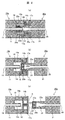
- FIG. 4 is a longitudinal sectional view of the aseptic connector of Example 3 according to another embodiment of the present invention, and FIG. 4 (a) shows a state in which the first connector and the second connector are connected. 4 (b) shows a state in the middle of pulling out the second connector from the first connector, and FIG. 4 (c) shows a state after the second connector is pulled out from the first connector.
- the first pipe line 13a constituting the first connector 10a of the second embodiment is formed in a needle shape
- the shape of the second connector 20 shown in the first embodiment is the second connector.
- the second embodiment is different from the first and second embodiments in that the outer diameter of the second housing is different between the region containing the second recess 24 and the region containing the second flow path.
- the same components as those in the first embodiment or the second embodiment are denoted by the same reference numerals, and the description thereof is omitted below.
- the configuration in which the connector is removed without applying pressure is the first configuration shown in FIG.
- the present invention is not limited to the configuration of the connector 10b and the second connector 20b, but can be similarly applied to the structure of the sterile connector of the first embodiment described above, that is, the configuration of the first connector 10 and the second connector 20 shown in FIG. . Further, the present invention can be similarly applied to the structure of the sterile connector according to the second embodiment described above, that is, the configuration of the first connector 10a and the second connector 20a shown in FIG.
- the liquid in the first flow path 11 is set to a negative pressure, that is, the first flow path is equivalently brought into the suction state, so that the first concave portion is removed from the needle-like first conduit 13b.
- the liquid can be prevented from leaking into the 16 spaces.
- an elastic tube (not shown) is connected to each of the first connector end 18 of the first connector 10b and the second connector end 26 of the second connector 20b, a pinch valve is connected to one elastic tube, and the other Connect the iron pump to the elastic tube. In the connection state shown in FIG. 4A, the pinch valve is closed, and the ironing pump is driven so that the liquid flows from the second channel 21 to the first channel 11.
- the second connector 20b is connected to the first connector as shown in FIGS. 4B and 4C. If it removes from 10b, it can prevent that a liquid leaks from the 1st opening part 12 of the 1st flow path 11.
- FIG. 1st connector 10b and the 2nd connector 20b which are shown in FIG. 4, but the 1st shown in the above-mentioned FIG.
- the present invention can be similarly applied to the configurations of the connector 10 and the second connector 20, and the first connector 10a and the second connector 20a shown in FIG.
- the sealing property (closing property) of the second connector 20b can be further improved.
- FIG. 5 shows a longitudinal sectional view of the first connector of Example 4 according to another example of the present invention.
- the present embodiment is different from the first embodiment in that a mechanism is provided for setting a positive pressure in the space of the first recess 16 in the first connector 10 shown in the first embodiment.
- Constituent elements similar to those of the first embodiment are denoted by the same reference numerals, and redundant description is omitted below.
- the first connector 10 c has one end communicating with the first recess 16 and the other end closed to form a closed space integrally with the first recess 16 and the volume of the closed space.
- the variable protrusion 14c has, for example, a bellows structure.
- the volume of the closed space formed integrally with the first recess 16 is reduced, and the space in the first recess 16 is made positive.
- the volume of the closed space formed integrally with the first recess 16 is expanded, and the inside of the space of the first recess 16 is set to a negative pressure.
- variable projection 14c When the variable projection 14c is pressed in a state where the first connector 10c is connected to the second connector 20 shown in FIG. 1, for example, the pressure in the space of the first recess 16 becomes positive.
- the liquid When the first connector 10c is pulled out from the second connector 20 while maintaining this state, the liquid is first introduced into the first flow path 11 from the first conduit 13 constituting the first connector 10c. It does not leak into the space of the recess 16 of the above. Therefore, the liquid is prevented from adhering to the outer surfaces of the second sealing member 23 constituting the second connector 20 and the end of the second housing 25 (the end defining the third opening 22). it can.
- the second connector is the second connector 20 of the first embodiment.
- the present invention is not limited to this, and the structure of the second connector 20a shown in FIG. 2 or the second connector 20b shown in FIG. Also good.
- it replaces with the 1st sealing member 17 and the 1st pipe line 13 which comprise the 1st connector 10c, and the 1st pipe line 13a and the 1st sealing member 17a which are shown in FIG. 2, or FIG.
- the variable protrusion 14c may be a structure that can be integrated with the first recess 16 to form a closed space.
- variable projection 14c a port capable of communicating with the first recess 16 is provided in the first housing 14, the pump and the port are connected by an elastic tube or the like, and the space of the first recess 16 is in a positive pressure state. It may be configured so that
- the first conduit in the first flow path is formed in the first flow path. It becomes possible to prevent liquid leakage.
- FIG. 6 shows an overall schematic configuration diagram of the cell culture device of Example 5 according to another example of the present invention.
- the cell culture apparatus 1 includes a cell culture container 31, a supply bag 32 containing a medium such as a cell culture solution, a recovery bag 33 that collects a medium such as a cell culture solution after use, and a flow.
- a path switching member 38 is provided.
- the cell culture container 31 is connected to the supply bag 32 and the collection bag 33 through a flow path.
- FIG. 6 shows an example in which four cell culture containers 31 are arranged, the present invention is not limited to this, and a desired number of cell culture containers 31 may be arranged.
- the cell culture apparatus 1 has one end connected to the supply back 32 and the other end connected to the upstream branch flow path 35 (upstream branch flow path connected to each cell culture vessel 31).
- the flow path 34 one end connected to the recovery bag 33, the other end connected to the flow path switching member 38, the downstream common flow path 37, and the downstream side connecting the flow path switching member 38 and each cell culture vessel 31
- a branch channel 36 (a downstream branch channel connected to each cell culture vessel 31) is provided.
- the cell culture apparatus 1 Since the cell culture apparatus 1 is a closed culture system, it is necessary to apply the driving force of a liquid such as a cell culture medium as a medium from outside the closed culture system. Therefore, a peristaltic pump 39 that permeates the elastic tube from the outside is disposed in the upstream common flow path 34. Therefore, at least a part of the upstream common channel 34 needs to be a channel having elasticity.
- the liquid such as the intracellular solution in the upstream common flow path 34 is pressurized and flows in the upstream common flow path 34 toward the cell culture container 31 side. That is, a positive pressure is generated in the flow path.
- the peristaltic pump 39 may be disposed in the downstream common flow path 37.
- the downstream common flow path 37 has a negative pressure, and a liquid such as a cell culture solution that is a medium is sucked out from the supply bag 32.
- the two squeezing pumps 39 arranged in the upstream common channel 34 and the downstream common channel 37 can reduce the pressure load on the liquid such as the cell culture fluid flowing in the channel.
- the liquid such as the cell culture solution in the supply bag 32 is sent to the cell culture container 31 through the upstream common channel 34 and the upstream branch channel 35.
- the flow is switched to the cell culture container 31 connected to the downstream common flow path 37 by the switching operation of the flow path switching member 38.
- the used cell culture liquid or the like that has remained in the cell culture container 31 until then is pushed out by the inflowing liquid such as the cell culture liquid, and the downstream branch flow path 36 and the flow path switching member 38. And it is sent to the collection bag 33 through the downstream common channel 37.
- FIG. 7 shows an integrated flow path member as an integrated member that combines the upstream and downstream common flow paths, the upstream and downstream branch flow paths, and the flow path switching member that constitute the cell culture apparatus shown in FIG.
- the external perspective view of this integrated flow path member and the cell culture container is shown.
- the cell culture vessel 41 includes a culture surface 41a, an inflow channel 41b and a discharge channel 41c described later.
- the integrated flow path member 42 includes a flow path switching member 43 and is configured to be connectable to the four cell culture containers 41.
- FIG. 8 is a longitudinal sectional view of the cell culture container and the accumulation channel member shown in FIG.
- the cell culture vessel 41 includes a culture surface 41a, an inflow channel 41b, and an exhaust channel 41c.
- the inflow channel 41b communicates with the culture surface 41a at an inlet 41e, and the exhaust channel 41c It communicates with the culture surface 41a at the outlet 41f.
- the integrated flow path member 42 includes an inlet 42a, an upstream common flow path 42b, an upstream branch flow path 42c, a downstream branch flow path 42d, a storage chamber 42e of the flow path switching member 43, and a downstream common flow path on the upper surface.
- a path 42f and a discharge port 42g are provided.
- the cell culture container 41 and the accumulation channel member 42 have a connection port 41d and a port 42h, respectively, so that they can be connected to each other.
- the integrated flow path member 42 includes a plurality of ports 42h that can be connected to a plurality of cell culture vessels 41.
- the cell culture vessel 41 and the collecting flow path member 42 are made of a plastic that is not toxic to cells such as polycarbonate, polystyrene, polypropylene, and has rigidity together with plasticity.
- An inflow channel 41b and an exhaust channel 41d are connected to the connection port 41d of the cell culture container 41.
- the inflow channel 41b and the exhaust channel 41d are connected to the connection port 41d on one side surface of the cell culture container 41. It is connected.
- the upstream branch flow path 42b and the downstream branch flow path 42d are connected to the port 42h of the integrated flow path member 42.
- the upstream branch flow path 42c and the downstream branch flow path 42d are connected to each of the integrated flow path members 42. It is connected with the port 42h up and down on the side.
- the upstream branch channel 42c and the inflow channel 41b of the cell culture container 41, the downstream branch channel 42d and the discharge channel 41c of the cell culture container 41 are used. Are configured to communicate with each other.
- the inlet channel 41b and the outlet channel 41d are connected to the connection port 41d on the same side surface of the cell culture container 41, and the upstream branch channel 42b and the downstream branch channel 42d are integrated flow. Since the structure is connected to the port 42 on each side surface of the path member 42, the cell culture container 41 can be attached to and detached from the integrated flow path member 42 from one direction, so that the attachment / detachment operation is facilitated.
- FIG. 9 is an enlarged view of the region B shown in FIG. 8, and is a partially enlarged view of a connection portion between the cell culture container 41 and the accumulation channel member 42.
- the second connector 20 shown in FIG. 1 is provided on the same side surface where the inflow channel 41b and the exhaust channel 41c of the cell culture vessel 41 are arranged, respectively. And it is provided up and down so as to be continuous with the discharge channel 41c.
- the first connector 10 shown in FIG. 1 is connected to the upstream branch flow path 42c and the downstream branch flow path 42d of the integrated flow path member 42 on the same side surface where the upstream branch flow path 42c and the downstream branch flow path 42d are arranged, respectively.
- the inflow channel 41b of the cell culture device 41 communicates with the upstream branch channel 42c of the integrated channel member 42 through the space of the second recess 24 of the second connector 20 while maintaining a closed system. Is done.
- the discharge channel 41 c of the cell culture device 41 maintains a closed system with the lower branch channel 42 d of the integrated channel member 42 through the space of the second recess 24 of the second connector 20. While communicating.
- the second sealing member 23 is caused by its own elastic force.
- the third opening 22 of the second connector 20 is closed.
- the inflow channel 41b and the discharge channel 41c of the cell culture container 41 are sealed.
- the first sealing member 17 closes the second opening 15 of the first connector 10 by its own elastic force.
- the upstream branch flow path 42c and the downstream branch flow path 42d of the integrated flow path member 42 are sealed.
- a configuration in which the first connector 10 illustrated in FIG. 1 is provided in the integrated flow path member 42 and the second connector 20 is provided in the cell culture container 41 is not limited thereto.
- One connector 10 may be provided in the cell culture container 41 and the second connector 10 may be provided in the accumulation channel member 42.
- the first connector 10a and the second connector 20a of the second embodiment may be used, and further, the aseptic connector shown in the third or fourth embodiment may be used.
- FIG. 10 is a vertical cross-sectional view of the integrated flow path member 42 shown in FIG.
- the flow path switching member 43 disposed in the storage chamber 42e includes a downstream branch flow path 42d communicating with the discharge flow path 41c of the desired culture vessel 41, a downstream common flow path 42f, and the like.
- a connection flow path is provided inside.
- a plurality of permanent magnets 50 are embedded without interfering with this connection flow path and spaced apart from each other in an annular shape.
- a plurality of electromagnets 51 made of a magnetic material with a coil wound are separated from each other and embedded in the integrated flow path member 42 at a position facing the permanent magnets 50 outside the storage chamber 42e. Yes.
- the flow path switching member 43 is rotated, so that the connection flow path is positioned at a position facing the desired downstream branch flow path 42d.
- the conducting wire for energizing the coil is routed to the outside of the closed cell culture device 1.
- the rotational axis of the flow path switching member 43 substantially coincides with the central axis of the lower common flow path 42f of the integrated flow path member 42.
- the drive mechanism of the flow path switching member 43 is not limited to the configuration including the permanent magnet 50 and the electromagnet 51 described above.
- the flow path switching member 43 extends so as to protrude from below the integrated flow path member 42 (the lower common flow path 42f side), and a rotational driving force is applied to the protruding portion by, for example, a stepping motor or a servo motor. It may be configured to transmit. In this case, in order to maintain a closed system, it is necessary to cover the periphery of the protrusion with, for example, a film-shaped sealing member.
- FIG. 11 is a partial vertical cross-sectional view of the connection portion between the cell culture container 41 and the accumulation channel member 42 shown in FIG. 8, and shows the structure of the fixing portion.
- FIG. 11 shows, as an example, a configuration in which the first connector 10a of Example 2 shown in FIG. 2 is provided so that the inflow channel 41b of the cell culture container 41 is continuous with the first channel.
- 2 shows a configuration in which the second connector 20a shown in FIG. 2 is provided so that the upper branch flow path 42c of the integrated flow path member 42 is continuous with the second flow path 21.
- the outer peripheral surface of the region containing the second flow path 21 (the upstream branch flow path 42c in FIG. 11) is divided into two parts.
- the 2nd connector 20a has the convex structure 52 formed in the annular
- the first connector 10a (connector including the inflow channel 41b of the cell culture container 41) is an annular shape at the outer peripheral surface of the first housing 14a and does not interfere with the first sealing member 17a.
- the concave structure 53 is provided. When the cell culture container 41 and the accumulation channel member 42 are connected, the concave structure 53 and the convex structure 52 are engaged with each other, thereby forming a snap-fit structure and preventing the cell culture container 41 from unintentionally falling off.
- the discharge channel 41c of the cell culture container 41 and the downstream branch channel 42d of the integrated channel member 42 have the same configuration as described above.
- FIG. 11 illustrates the case where the first connector 10a and the second connector 20b of the second embodiment shown in FIG. 2 are used as the first connector and the second connector constituting the aseptic connector.
- the sterile connector of Example 1 shown in FIG. 1 the sterile connector of Example 3 shown in FIG. 4, or the sterile connector of Example 4 shown in FIG. 5 may be used as the sterile connector.
- FIG. 12 is a view showing a modification of the cell culture container and the accumulation channel member constituting the cell culture apparatus shown in FIG. 7,
- FIG. 12 (a) is a top view of the cell culture container, and
- FIG. It is an external appearance perspective view of a cell culture container and an accumulation channel member. 7 and 8 described above, the inflow channel 41b and the exhaust channel 41c in the cell culture container 41 are arranged vertically with respect to the culture surface 41a, and the upstream branch channel 42c of the integrated channel member 42 and The downstream branch flow path 42d is arranged vertically within the same side surface.
- the inflow channel 41b and the exhaust channel 41c in the cell culture container 41 are arranged vertically with respect to the culture surface 41a, and the upstream branch channel 42c of the integrated channel member 42 and The downstream branch flow path 42d is arranged vertically within the same side surface.
- the culture surface 41a communicates with the culture surface 41a at two locations on the diagonal line of the culture surface 41a on the bottom surface side of the cylindrical culture surface 41a, and has a circular cross section.
- An inflow channel 41b and a discharge channel 41c extending in parallel to the tangential direction of the surface 41a in the same horizontal plane are provided. Thereby, the inflow channel 41b and the exhaust channel 41c are connected to the connection port 41d in the horizontal direction on the same side surface of the cell culture container 41.
- the integrated flow path member 42 has the entire side surface (only one side is illustrated in FIG. 12B) as a whole, for example, a sealing member 54 made of an elastic body such as rubber.
- the slits 55 are respectively provided at positions that are opposite to the inlet channel 41b and the outlet channel 41c of the cell culture container 41 and that can be inserted.
- a connector continuous with the upstream branch flow path 42b is located at the position of each slit 55, that is, the slit 55 facing the inflow flow path 41b. It is arranged in.
- a connector continuous with the downstream branch flow path 42d is disposed in the integrated flow path member 42 at the position of the slit 55 facing the discharge flow path 41c.
- a number of parts can be reduced compared with the structure shown in FIG. That is, in FIG. 9, two sealing members are arranged on each side surface of the integrated flow path member 42, but in the configuration shown in FIG. 12C, one sealing member is arranged on one side surface. Can be halved.
- the slits 55 may be formed in accordance with the number of flow paths connected to each other, and three slits 55 or four slits 55 may be formed on the same side surface of the integrated flow path member 42.
- the flow path switching member 43 has a connection flow path that can connect the downstream common flow path 42f and the downstream branch flow path 42d.
- the present invention is not limited to this.
- a configuration having a connection channel that enables connection between the upstream common channel 42 b and the upstream branch channel 42 c and a configuration in which the connection channel is arranged in the upper part of the integrated channel member 42 may be adopted.
- this invention is not limited to the above-mentioned Example, Various modifications are included.
- the above-described embodiments have been described in detail for easy understanding of the present invention, and are not necessarily limited to those having all the configurations described.
- a part of the configuration of one embodiment can be replaced with the configuration of another embodiment, and the configuration of another embodiment can be added to the configuration of one embodiment.
- SYMBOLS 1 Cell culture apparatus, 10, 10a, 10b ... 1st connector, 11 ... 1st flow path, 12 ... 1st opening part, 13, 13a, 13b ... 1st pipe line, 14, 14a, 14b ... 1st housing, 14c ... Variable projection part, 15 ... 2nd opening part, 16 ... 1st recessed part, 17, 17a, ... 1st sealing member, 17A ... 1st slit, 18 ... 1st Connector end, 20, 20a ... second connector, 21 ... second flow path, 22 ... third opening, 23, 23a, 23b ... second sealing member, 23A ... second slit, 24 ...
Landscapes
- Health & Medical Sciences (AREA)
- Life Sciences & Earth Sciences (AREA)
- Organic Chemistry (AREA)
- Engineering & Computer Science (AREA)
- Bioinformatics & Cheminformatics (AREA)
- Chemical & Material Sciences (AREA)
- Zoology (AREA)
- Wood Science & Technology (AREA)
- Sustainable Development (AREA)
- Microbiology (AREA)
- Biotechnology (AREA)
- Biomedical Technology (AREA)
- Biochemistry (AREA)
- General Engineering & Computer Science (AREA)
- General Health & Medical Sciences (AREA)
- Genetics & Genomics (AREA)
- Clinical Laboratory Science (AREA)
- Molecular Biology (AREA)
- Apparatus Associated With Microorganisms And Enzymes (AREA)
Abstract
A sterile connector is provided with a first connector 10 that comprises: a first housing 14 provided with a first flow channel 11 for flowing a fluid therethrough; a first pipeline 13 connected to the first flow channel 11; a first opening 12 and a second opening 14, said first opening 12 being positioned inward from the second opening 15 along the axial direction of the first housing 14; and a first sealing member 17 covering the second opening 15. Also, the sterile connector is provided with a second connector that comprises: a second housing 25 provided with a second flow channel 21 for flowing a fluid therethrough; a third opening 22; and a second sealing member 23 covering the third opening 22. The first and second connectors 10 and 20 are detachable from each other. The first sealing member 17 seals a space between the inner circumferential surface of the first housing 14 and the outer circumferential surface of the second housing 25, while the second sealing member 23 seals a space between the inner circumferential surface of the second housing 25 and the outer circumferential surface of the first pipeline 13 so that the first flow channel 11 is communicated with the second flow channel 21.
Description
本発明は、無菌コネクタ及びそれを有する細胞培養装置に係り、特に、閉鎖系の細胞培養装置から細胞培養容器等を無菌的に取外す場合に好適な無菌コネクタ及びそれを有する細胞培養装置に関する。
The present invention relates to a sterile connector and a cell culture apparatus having the same, and more particularly to a sterile connector suitable for aseptically removing a cell culture container from a closed cell culture apparatus and a cell culture apparatus having the same.
細胞培養において、外部からのコンタミネーションを防ぐために、密閉型の細胞培養容器に培地バッグや排液バッグを、チューブを介して接続し、この閉じた系(閉鎖系)の中で培養を行う閉鎖系細胞培養装置が一般的に用いられている。
In cell culture, in order to prevent external contamination, a closed cell culture container is connected to a closed cell culture container via a tube, and culture is performed in this closed system (closed system). A cell culture apparatus is generally used.
また、外部からのコンタミネーションを防止しつつ、異なる2つの流路を接続可能とする無菌コネクタアセンブリとして、特許文献1に記載される構造が提案されている。この無菌コネクタアセンブリは、第1コネクタ及び第2コネクタよりなり、第1コネクタは、内部に流路を画定するステム、このステムを包囲し且つ第1開口部を画定する第1ハウジング及び第1開口部の上に配置される第1弁を有する。また、第2のコネクタは、第1ハウジングと嵌合するよう構成され、第2開口部を画定する第2ハウジング、第2開口部の上に配置される第2弁を有する。そして、第1ハウジングと第2ハウジングが係合すると、第1弁と第2弁とが係合する構成を備えている。
Also, a structure described in Patent Document 1 has been proposed as an aseptic connector assembly that can connect two different flow paths while preventing external contamination. The aseptic connector assembly includes a first connector and a second connector. The first connector includes a stem that defines a flow path therein, a first housing that surrounds the stem and defines a first opening, and a first opening. A first valve disposed on the section. The second connector is configured to mate with the first housing and includes a second housing defining the second opening and a second valve disposed on the second opening. When the first housing and the second housing are engaged, the first valve and the second valve are engaged.
しかしながら、特許文献1に記載される無菌コネクタアセンブリは、第1コネクタの第1弁と第2コネクタの第2弁とを当接させた後、第1コネクタ内のステムを第2コネクタ側へ移動させることにより、ステムが第1弁及び第2弁を押し開き、これら第1弁及び第2弁を折り畳むよう係合することで封止するものである。
However, in the aseptic connector assembly described in Patent Document 1, after the first valve of the first connector and the second valve of the second connector are brought into contact with each other, the stem in the first connector is moved to the second connector side. By doing so, the stem pushes open the first valve and the second valve, and the first valve and the second valve are folded and engaged to be sealed.
従って、第1コネクタ及び第2コネクタのうちいずれか一方を他方側へ押し込むことのみでは、第1弁及び第2弁の係合はなし得ず、第1コネクタ内のステムを移動さるという2段階の操作が必要となる。仮に、この2段階操作の手順を取り違えた場合、例えば、第1コネクタを第2コネクタより引き抜く場合において、第1及び第2弁によるそれぞれの流路の封止ができず、外部からの微生物あるいは細菌類等を含む粒子の侵入を招く恐れがある。また、2段階操作を要するものであるため、作業者による作業性の向上は望めない。
Therefore, the first valve and the second valve cannot be engaged only by pushing one of the first connector and the second connector to the other side, and the stem in the first connector is moved. Operation is required. If the two-step operation procedure is mistaken, for example, when the first connector is pulled out from the second connector, the first and second valves cannot be sealed, and microorganisms from the outside or There is a risk of invasion of particles containing bacteria. In addition, since two-step operation is required, improvement in workability by the worker cannot be expected.
一方、例えば細胞シートを用いた角膜の移植の治験では、前日に複数の細胞培養容器で培養していた中から一個の細胞培養容器の細胞シートを取り出し、検査することが手順化されている。今後大量の細胞を培養する場合、培養細胞の品質を検査するため、一部の培養細胞を取り出し評価することが考えられる。複数の細胞培養容器が接続される閉鎖系の細胞培養装置において、全体の閉鎖系を保ちながら上記のように細胞を取り出して検査することが望まれている。
On the other hand, in a clinical trial of corneal transplantation using, for example, a cell sheet, it is a procedure to take out and inspect a cell sheet in one cell culture container from the cells cultured in a plurality of cell culture containers on the previous day. In the case of culturing a large amount of cells in the future, in order to inspect the quality of the cultured cells, it is considered that some cultured cells are taken out and evaluated. In a closed cell culture apparatus to which a plurality of cell culture containers are connected, it is desired to take out and inspect cells as described above while maintaining the entire closed system.
そこで、本発明は、外界からの微生物あるいは細菌類等を含む粒子の侵入を防止しつつ、閉鎖系の細胞培養装置から所望の細胞培養容器を容易に取り出し得る無菌コネクタ及びそれを有する細胞培養装置を提供することにある。
Accordingly, the present invention provides a sterile connector capable of easily taking out a desired cell culture vessel from a closed cell culture device while preventing invasion of particles containing microorganisms or bacteria from the outside, and a cell culture device having the same. Is to provide.
上記課題を解決するため、本発明の無菌コネクタは、(1)内部に流体を通流させる第1の流路を有する第1のハウジングと、前記第1の流路と連続する第1の管路と、当該第1の管路の一端が解放されてなる第1の開口部と、前記第1のハウジングの端部により画定される第2の開口部と、前記第1の開口部は前記第2の開口部より前記第1のハウジングの軸方向内側に配され、前記第2の開口部を覆う第1の封止部材と、を有する第1のコネクタと、(2)内部に流体を通流させる第2の流路を有する第2のハウジングと、前記第2のハウジングの端部により画定される第3の開口部と、前記第3の開口部を覆う第2の封止部材と、を有する第2のコネクタと、を備え、前記第1及び第2のコネクタは、相互に着脱可能であって、前記第1の封止部材が、前記第2の開口部を画定する第1のハウジングの内周面と前記第2のハウジングの外周面との間隙を封止し、前記第2の封止部材が、前記前記第3の開口部を画定する第2のハウジングの内周面と前記第1の管路の外周面との間隙を封止し、前記第1の流路及び第2の流路を連通することを特徴とする。
In order to solve the above-mentioned problems, an aseptic connector of the present invention includes (1) a first housing having a first flow path for allowing fluid to flow inside, and a first tube continuous with the first flow path. A first opening in which one end of the first pipe line is released, a second opening defined by an end of the first housing, and the first opening A first connector having a first sealing member disposed on the inner side in the axial direction of the first housing from the second opening and covering the second opening; (2) fluid inside A second housing having a second flow path for flow, a third opening defined by an end of the second housing, and a second sealing member covering the third opening. A second connector having the first and second connectors, wherein the first and second connectors are detachable from each other, 1 sealing member seals a gap between the inner peripheral surface of the first housing and the outer peripheral surface of the second housing that defines the second opening, and the second sealing member includes: The gap between the inner peripheral surface of the second housing defining the third opening and the outer peripheral surface of the first conduit is sealed, and the first flow path and the second flow path are communicated with each other. It is characterized by doing.
また、本発明の細胞培養装置は、培養に要する液体を通流する流入流路と使用後の液体を排出する排出流路を有する細胞培養容器と、複数の細胞培養容器を並列接続可能に構成され、各細胞培養容器に対応して上流側分岐流路及び下流側分岐流路を有し、少なくとも、前記複数の細胞培養容器のうちいずれか所望の細胞培養容器へ、前記上流側分岐流路を介して前記流入流路へ培養に要する液体を送液する集積流路部材と、を備え、前記集積流路部材は、前記上流側分岐流路及び前記下流側分岐流路のそれぞれと連続する第1の管路を有する第1のハウジングと、各第1の管路の一端が解放されてなる第1の開口部と、前記第1のハウジングの端部により画定される第2の開口部と、前記第2の開口部を覆う第1の封止部材とを備え、前記細胞培養容器は、前記流入流路及び排出流路をそれぞれ内包する第2のハウジングと、前記第2のハウジングの端部により画定される第3の開口部と、前記第3の開口部を覆う第2の封止部材とを備え、前記第1の封止部材が、前記第1のハウジングの内周面と前記第2のハウジングの外周面との間隙を封止し、前記第2の封止部材が、前記第2のハウジングと前記第1の管路の外周面との間隙を封止し、前記細胞培養容器を前記集積流路部材に接続することを特徴とする。
In addition, the cell culture device of the present invention is configured such that a cell culture container having an inflow channel through which a liquid required for culture flows and a discharge channel through which liquid after use is discharged, and a plurality of cell culture containers can be connected in parallel. The upstream branch channel and the downstream branch channel corresponding to each cell culture vessel, and at least the upstream branch channel to any desired cell culture vessel of the plurality of cell culture vessels An integrated flow path member for feeding a liquid required for culture to the inflow flow path via the flow path, and the integrated flow path member is continuous with each of the upstream branch flow path and the downstream branch flow path A first housing having a first conduit; a first opening formed by releasing one end of each first conduit; and a second opening defined by an end of the first housing And a first sealing member that covers the second opening, The cyst culture container covers a second housing enclosing the inflow channel and the outflow channel, a third opening defined by an end of the second housing, and the third opening. A second sealing member, and the first sealing member seals a gap between an inner peripheral surface of the first housing and an outer peripheral surface of the second housing, and the second sealing member. The stop member seals the gap between the second housing and the outer peripheral surface of the first conduit, and connects the cell culture container to the accumulation channel member.
また、本発明の細胞培養容器は、培養に要する液体を通流する流入流路と使用後の液体を排出する排出流路を有する細胞培養容器と、複数の細胞培養容器を並列接続可能に構成され、各細胞培養容器に対応して上流側分岐流路及び下流側分岐流路を有し、少なくとも、前記複数の細胞培養容器のうちいずれか所望の細胞培養容器へ、前記上流側分岐流路を介して前記流入流路へ培養に要する液体を送液する集積流路部材と、を備え、前記細胞培養容器は、前記流入流路及び前記排出流路のそれぞれと連続する第1の管路を有する第1のハウジングと、各第1の管路の一端が解放されてなる第1の開口部と、前記第1のハウジングの端部により画定される第2の開口部と、前記第2の開口部を覆う第1の封止部材とを備え、前記集積流路部材は、前記上流側分岐流路及び下流側分岐流路をそれぞれ内包する第2のハウジングと、前記第2のハウジングの端部により画定される第3の開口部と、前記第3の開口部を覆う第2の封止部材とを備え、前記第1の封止部材が、前記第1のハウジングの内周面と前記第2のハウジングの外周面との間隙を封止し、前記第2の封止部材が、前記第2のハウジングと前記第1の管路の外周面との間隙を封止し、前記細胞培養容器を前記集積流路部材に接続することを特徴とする。
In addition, the cell culture container of the present invention is configured such that a cell culture container having an inflow channel through which a liquid required for culture flows and a discharge channel through which liquid after use is discharged can be connected in parallel to a plurality of cell culture containers. The upstream branch channel and the downstream branch channel corresponding to each cell culture vessel, and at least the upstream branch channel to any desired cell culture vessel of the plurality of cell culture vessels And a collecting channel member for sending a liquid required for culture to the inflow channel via the first channel that is continuous with the inflow channel and the discharge channel. A first opening formed by releasing one end of each first conduit, a second opening defined by the end of the first housing, and the second A first sealing member that covers the opening of the integrated flow path member And a second housing enclosing each of the upstream branch flow path and the downstream branch flow path, a third opening defined by an end of the second housing, and covering the third opening. A second sealing member, and the first sealing member seals a gap between an inner peripheral surface of the first housing and an outer peripheral surface of the second housing, and the second sealing member. The stop member seals the gap between the second housing and the outer peripheral surface of the first conduit, and connects the cell culture container to the accumulation channel member.
本発明によれば、外界からの微生物あるいは細菌類等を含む粒子の侵入を防止しつつ、閉鎖系の細胞培養装置から所望の細胞培養容器を容易に取り出し得る無菌コネクタ及びそれを有する細胞培養装置を提供することが可能となる。
According to the present invention, a sterile connector capable of easily taking out a desired cell culture container from a closed cell culture apparatus while preventing invasion of particles containing microorganisms or bacteria from the outside, and a cell culture apparatus having the same Can be provided.
上記した以外の課題、構成及び効果は、以下の実施形態の説明により明らかにされる。
Issues, configurations, and effects other than those described above will be clarified by the following description of the embodiments.
以下、本発明の実施例について図面を用いて説明する。
Hereinafter, embodiments of the present invention will be described with reference to the drawings.
図1は、本発明の一実施例に係る実施例1の無菌コネクタの概略構成図であり、図1(a)に、無菌コネクタを構成する第1のコネクタ10と第2のコネクタ20が接続された状態を示し、図1(b)に、第1のコネクタ10より第2のコネクタ20を引き抜く(取り外す)途中段階の状態を示し、図1(c)に、第1のコネクタ10から第2のコネクタ20が引き抜かれ(取り外され)、相互に離間する状態を示す。
FIG. 1 is a schematic configuration diagram of a sterile connector according to a first embodiment of the present invention. In FIG. 1A, the first connector 10 and the second connector 20 constituting the sterile connector are connected. FIG. 1B shows a state in the middle of pulling out (removing) the second connector 20 from the first connector 10, and FIG. 1C shows the state from the first connector 10 to the first connector 10. 2 shows a state in which the two connectors 20 are pulled out (detached) and separated from each other.
図1(c)に示すように、第1のコネクタ10は、円筒状の第1のハウジング14内に、内部に流体を通流する第1の流路11、一端に第1のハウジング14により画定される第2の開口部15、他端に第1のコネクタ端18、及び第1の流路11の端部に形成され(連続して形成され)、第1のハウジング14の内径よりも小さい外径を有する円筒状の第1の管路13を備える。
As shown in FIG. 1 (c), the first connector 10 includes a first flow path 11 through which a fluid flows and a first housing 14 at one end. The second opening 15 is defined, the first connector end 18 is formed at the other end, and the end of the first flow path 11 is formed (continuously formed), and the inner diameter of the first housing 14 is larger than that of the first housing 14. A cylindrical first conduit 13 having a small outer diameter is provided.
第1の管路13の先端部は、第1のコネクタ10の軸方向に沿って、第2の開口部15を画定する第1のハウジング14の端部より所定の距離だけ、第1のコネクタ10の軸方向内側に位置する。また、第1の管路13の先端部は開放され第1の開口部12を成し、この第1の開口部12は第1の流路11と連通する。第1の管路13の外周面と第1のハウジング14の内周面により、縦断面凹形状の空間である第1の凹部16が形成される。換言すれば、第2の開口部15を画定する第1のハウジング14の端部より、第1のコネクタ10の軸方向に沿ってその内部へと連続する円柱状の空間内に、第1のハウジング14の内径よりも小さな外径を有する第1の管路13が、内部に第1の流路11を有し、第2の開口部15側へと向かい突き出るよう縦断面凸状に形成されている。
The distal end portion of the first conduit 13 extends along the axial direction of the first connector 10 by a predetermined distance from the end of the first housing 14 that defines the second opening 15. 10 axially inside. Further, the distal end portion of the first conduit 13 is opened to form a first opening 12, and the first opening 12 communicates with the first flow path 11. A first concave portion 16 that is a space having a concave shape in the longitudinal section is formed by the outer peripheral surface of the first duct 13 and the inner peripheral surface of the first housing 14. In other words, from the end of the first housing 14 that defines the second opening 15, the first connector 10 extends into the cylindrical space that continues to the inside along the axial direction of the first connector 10. A first pipe line 13 having an outer diameter smaller than the inner diameter of the housing 14 has a first flow path 11 therein and is formed in a convex shape in a vertical cross section so as to protrude toward the second opening 15 side. ing.
第2の開口部15を画定する第1のハウシング14の端部には、第2の開口部15を塞ぐよう円板状の第1の封止部材17が設けられている。この円板状の第1の封止部材17は、その外周面が第1のハウジング14の内周面に固定されると共に、略中央部に一条の第1のスリット17Aを有する。
A disc-shaped first sealing member 17 is provided at the end of the first housing 14 that defines the second opening 15 so as to close the second opening 15. The disc-shaped first sealing member 17 has an outer peripheral surface fixed to the inner peripheral surface of the first housing 14 and has a single first slit 17A at a substantially central portion.
また、第2のコネクタ20は、円筒状の第2のハウジング25内に、内部に流体を通流する第2の流路21、一端に第2のハウジング25により画定される第3の開口部22、及び他端に第2のコネクタ端26を備える。第3の開口部22を画定する第2のハウジング25の端部より、第2のコネクタ20の軸方向に沿って第2の流路21の先端部まで連続する、第2のハウジンン25の内周面により画定される円柱状の空間である第2の凹部24が形成される。第2の凹部24を画定する第2のハウジング25の内径は、第2の流路21の直径よりも大きく、第1の流路11の直径は、第2の流路21の直径とほぼ等しい。第3の開口部22を画定する第2のハウジング25の端部には、第3の開口部22を塞ぐよう円板状の第2の封止部材23が設けられている。この円板状の第2の封止部材23は、その外周面が第2のハウジング25の内周面に固定されると共に、略中央部に一条の第2のスリット23Aを有する。ここで、第1の封止部材17の外周面と第1のハウジング14の内周面との固定、及び、第2の封止部材23の外周面と第2のハウジング25の内周面との固定は、例えば、接着剤による接着や熱溶着する等により行われる。なお、接着する際は、細胞毒性のない接着剤を使用する等、細胞に影響を与えない接着方法が望ましい。
The second connector 20 has a cylindrical second housing 25, a second flow path 21 through which fluid flows, and a third opening defined by the second housing 25 at one end. 22 and a second connector end 26 at the other end. The inside of the second housing 25 that continues from the end of the second housing 25 that defines the third opening 22 to the tip of the second flow path 21 along the axial direction of the second connector 20. A second recess 24, which is a cylindrical space defined by the peripheral surface, is formed. The inner diameter of the second housing 25 that defines the second recess 24 is larger than the diameter of the second flow path 21, and the diameter of the first flow path 11 is substantially equal to the diameter of the second flow path 21. . A disc-shaped second sealing member 23 is provided at the end of the second housing 25 that defines the third opening 22 so as to close the third opening 22. The disc-shaped second sealing member 23 has an outer peripheral surface fixed to the inner peripheral surface of the second housing 25 and has a second slit 23 </ b> A at a substantially central portion. Here, the outer peripheral surface of the first sealing member 17 and the inner peripheral surface of the first housing 14 are fixed, and the outer peripheral surface of the second sealing member 23 and the inner peripheral surface of the second housing 25 are Is fixed by, for example, bonding with an adhesive or heat welding. When adhering, an adhesion method that does not affect the cells, such as using an adhesive having no cytotoxicity, is desirable.
第1のコネクタ10の第1の管路13の外径は、第2のコネクタ20の第3の開口部22を画定する第2のハウジング25の端部の内径より小さい。また、第2のコネクタ20の第2のハウジング25の外径は、第1のコネクタ10の第2の開口部15を画定する第1のハウジング14の内径よりも小さい。
The outer diameter of the first conduit 13 of the first connector 10 is smaller than the inner diameter of the end of the second housing 25 that defines the third opening 22 of the second connector 20. Further, the outer diameter of the second housing 25 of the second connector 20 is smaller than the inner diameter of the first housing 14 that defines the second opening 15 of the first connector 10.
また、第1の封止部材17及び第2の封止部材23は、弾性を有し密着性に優れ、かつ滅菌が可能である材質であることが好ましく、例えばゴム等の弾性体が好適である。また、第1の流路11及び第2の流路21を構成する部材、すなわち、第1のハウジング14及び第2のハウジング25は、例えば、ポリカーボネート、ポリスチレン、ポリプロピレン等の細胞に対し毒性が無く、可塑性と共に剛性を有するプラスチックで形成することが望ましい。なお、プラスチックに替えて、細胞に対し毒性の無い金属で形成しても良い。
The first sealing member 17 and the second sealing member 23 are preferably made of a material that has elasticity, excellent adhesion, and can be sterilized. For example, an elastic body such as rubber is preferable. is there. Further, the members constituting the first flow path 11 and the second flow path 21, that is, the first housing 14 and the second housing 25 are not toxic to cells such as polycarbonate, polystyrene, polypropylene, and the like. It is desirable to form with plastic which has both plasticity and rigidity. Instead of plastic, it may be formed of a metal that is not toxic to cells.
次に、第1のコネクタ10及び第2のコネクタ20により構成される無菌コネクタ引き抜き(取り外し)動作について説明する。
Next, the aseptic connector pulling out (removing) operation constituted by the first connector 10 and the second connector 20 will be described.
図1(a)の左図は、第1のコネクタ10と第2のコネクタ20が接続あるいは嵌合した状態での縦断面図であり、右図はA-A横断面矢視図である。第1のコネクタ10及び第2のコネクタ20のうち、いずれか一方を他方側へと押し込むことで接続あるいは嵌合状態となる。なお、以下では、一例として、第1のコネクタ10を固定し、第2のコネクタ20を移動させる場合を例とし、説明する。
1A is a vertical cross-sectional view in a state where the first connector 10 and the second connector 20 are connected or fitted, and the right view is a cross-sectional view taken along the line AA. Either one of the first connector 10 and the second connector 20 is pushed into the other side to be connected or fitted. Hereinafter, as an example, the case where the first connector 10 is fixed and the second connector 20 is moved will be described as an example.
図1(a)の左図に示すように、第1のコネクタ10を構成する第1の管路13の外周面と、第2のコネクタ20の第2の開口部22を画定する第2のハウジング25の内周面との間隙は、第2の封止部材23により封止されている。また、第2のコネクタ20の第2のハウジング25の外周面と、第1のコネクタ10の第2の開口部15を画定する第1のハウジング14の内周面との間隙は、第1の封止部材17により封止されている。そして、第1の流路11及び第2の流路21は、第2の凹部24を介して連通する。このとき、図1(a)の右図に示すように、第1の開口部12を中心として、同心円状に径方向に、第1の管路13、第2の封止部材23、第2のハウジング25、第1の封止部材17及び第1のハウジング14と配され、第1の封止部材17及び第2の封止部材23により密閉性が確立される。すなわち、閉鎖系を保ちつつ、第1の流路11及び第2の流路21を連通することが可能となる。これは、上述のとおり第1の封止部材17の略中央部に設けられた一条の第1のスリット17Aを介して、第2のハウジング25の先端部が第1のコネクタ10側へ挿通することにより、第1の封止部材17は、第1のハウジング14の内周面側と押し込まれる。そして、第2の封止部材23の略中央に設けられた一条の第2のスリット23Aを介して、第1の管路13の先端部により第2の封止部材23が、第2のハウジング25の内周面側へと押し込まれることによる。
As shown in the left diagram of FIG. 1A, the second outer surface defining the first conduit 13 constituting the first connector 10 and the second opening 22 of the second connector 20 are defined. A gap with the inner peripheral surface of the housing 25 is sealed with a second sealing member 23. Further, the gap between the outer peripheral surface of the second housing 25 of the second connector 20 and the inner peripheral surface of the first housing 14 that defines the second opening 15 of the first connector 10 is the first gap. It is sealed with a sealing member 17. The first flow path 11 and the second flow path 21 communicate with each other through the second recess 24. At this time, as shown in the right view of FIG. 1A, the first conduit 13, the second sealing member 23, and the second concentrically in the radial direction around the first opening 12. The housing 25, the first sealing member 17, and the first housing 14 are arranged, and hermeticity is established by the first sealing member 17 and the second sealing member 23. That is, the first flow path 11 and the second flow path 21 can be communicated while maintaining a closed system. As described above, the distal end portion of the second housing 25 is inserted into the first connector 10 through the first slit 17A provided in the substantially central portion of the first sealing member 17 as described above. Accordingly, the first sealing member 17 is pushed into the inner peripheral surface side of the first housing 14. Then, the second sealing member 23 is connected to the second housing by the distal end portion of the first pipe line 13 through a single second slit 23A provided in the approximate center of the second sealing member 23. By being pushed into the inner peripheral surface side of 25.
図1(a)に示す接続あるいは嵌合状態から、第2のコネクタ20を紙面に向かい右方向へ移動させると、図1(b)に示す、第1のコネクタ10より第2のコネクタ20を引き抜く(取り外す)途中の状態となる。図1(b)の左図に示すように、第3の開口部22を画定する第2のハウジング25の端部が、第1の管路13の先端部すなわち、第1の開口部12より、紙面に向かって右方向に移動することにより離間する。このとき、第2の封止部材23を第2のハウジング内周面側へ押し込んでいた第1の管路13が、第2のハウジン25の端部から離脱することにより、例えば、ゴム等の弾性体で形成される第2の封止部材23は、自身の弾性力により第3の開口部22を封止する状態となる。この状態では、未だ、第3の開口部22を画定する第2のハウジング25の先端部は、第2の開口部15を画定する第1のハウジング14の内部に位置する。これにより、第2のハウジング25の外周面と第1のハウジング14の内周面との間隙は、第1の封止部材17により封止された状態を維持する。図1(b)の右図に示すように、第2の封止部材23の中央を中心として、同心円状に径方向に、第2のハウジング25、第1の封止部材17及び第1のハウジング14と配され、第2の封止部材23により第3の開口部22が封止されることで、第2の流路21は密閉(閉鎖)される。図1(b)の右図では、第2のスリット23Aを図示していないが、これは、上述のように第2の封止部材23の弾性力により、第3の開口部22が自動的に密閉状態となり、このとき、それまで第1の管路13が挿通されていた第2のスリット23Aは、弾性力により閉塞されるため図示を省略している。
When the second connector 20 is moved to the right from the connection or fitting state shown in FIG. 1A, the second connector 20 is moved from the first connector 10 shown in FIG. It will be in the state of being pulled out (removed). As shown in the left diagram of FIG. 1B, the end of the second housing 25 that defines the third opening 22 is more than the tip of the first conduit 13, that is, the first opening 12. They are separated by moving in the right direction toward the page. At this time, when the first conduit 13 that has pushed the second sealing member 23 toward the inner peripheral surface of the second housing is detached from the end of the second housing 25, for example, rubber or the like The 2nd sealing member 23 formed with an elastic body will be in the state which seals the 3rd opening part 22 with an own elastic force. In this state, the distal end portion of the second housing 25 that defines the third opening 22 is still located inside the first housing 14 that defines the second opening 15. As a result, the gap between the outer peripheral surface of the second housing 25 and the inner peripheral surface of the first housing 14 is maintained in a state of being sealed by the first sealing member 17. As shown in the right view of FIG. 1B, the second housing 25, the first sealing member 17 and the first sealing member 23 are arranged concentrically in the radial direction around the center of the second sealing member 23. The second channel 21 is sealed (closed) by being arranged with the housing 14 and sealing the third opening 22 by the second sealing member 23. In the right view of FIG. 1B, the second slit 23A is not shown, but this is because the third opening 22 is automatically formed by the elastic force of the second sealing member 23 as described above. At this time, the second slit 23A through which the first pipe 13 has been inserted until then is closed by the elastic force, and is not shown.
図1(b)に示す状態から、更に、第2のコネクタ20を紙面に向かい右方向へ移動させると、図1(c)に示す状態となる。図1(c)の左図は、第1のコネクタ10から第2のコネクタ20が引き抜かれた後の状態を示している。図1(b)に示す状態から、更に、第2のコネクタ20を紙面に向かい右方向へ移動させると、第3の開口部22を画定する第2のハウジング25の端部が、第2の開口部15を画定する第1のハウジング14の端部より離間する。このとき、第2の開口部15を画定する第1のハウジング14の端部が、それまで第1の封止部材17を第1のハウジング14の内周面側へ押し込んでいた第2のハウジング25より離脱する。これにより、例えば、ゴム等の弾性体で形成される第1の封止部材17は、自身の弾性力により第2の開口部15を封止する状態となる。第1のスリット17Aは、第2の封止部材23と同様に、弾性力により閉塞される。これにより、第1のコネクタ10及び第2のコネクタ20は、それぞれ、第1の封止部材17及び第2の封止部材23により、閉鎖系を保ちつつ、取り外しが可能となる。
When the second connector 20 is further moved rightward from the state shown in FIG. 1B toward the paper surface, the state shown in FIG. 1C is obtained. The left view of FIG. 1C shows a state after the second connector 20 is pulled out from the first connector 10. When the second connector 20 is further moved rightward from the state shown in FIG. 1B toward the paper surface, the end of the second housing 25 that defines the third opening 22 becomes the second It is spaced apart from the end of the first housing 14 that defines the opening 15. At this time, the end of the first housing 14 that defines the second opening 15 has pushed the first sealing member 17 into the inner peripheral surface of the first housing 14 until then. Leave from 25. Thereby, the 1st sealing member 17 formed with elastic bodies, such as rubber | gum, will be in the state which seals the 2nd opening part 15 with an own elastic force, for example. Similarly to the second sealing member 23, the first slit 17A is closed by an elastic force. Thereby, the 1st connector 10 and the 2nd connector 20 can be removed by the 1st sealing member 17 and the 2nd sealing member 23, respectively, maintaining a closed system.
本実施例では、第1のコネクタ10を固定し、第2のコネクタ20を移動させる例を説明したが、これに替えて、第2のコネクタ20を固定し、第1のコネクタ10を移動させても上述と同様の機能が達成される。
In the present embodiment, the example in which the first connector 10 is fixed and the second connector 20 is moved has been described, but instead, the second connector 20 is fixed and the first connector 10 is moved. However, the same function as described above is achieved.
本実施例によれば、第1の流路11を有する第1のコネクタ10と、第2の流路21を有する第2のコネクタ20を、閉鎖系を保ちつつ取り外すことが可能となる。
According to the present embodiment, the first connector 10 having the first flow path 11 and the second connector 20 having the second flow path 21 can be removed while maintaining a closed system.
また、これにより第1の流路11あるいは第2の流路21へ、外界から微生物あるいは細菌類等を含む粒子の侵入を防止しつつ、一方のコネクタを一方向へ移動することのみで取り外しを可能とする無菌コネクタを実現できる。
In addition, this prevents the particles including microorganisms or bacteria from entering the first flow path 11 or the second flow path 21 from the outside, and is removed only by moving one connector in one direction. A possible aseptic connector can be realized.
図2に、本発明の他の実施例に係る実施例2の無菌コネクタの縦断面である。図2(a)は第1のコネクタ及び第2のコネクタが接続された状態を示し、図2(b)は第1のコネクタより第2のコネクタを引き抜く途中段階の状態を示し、図2(c)は第1のコネクタから第2のコネクタ引抜後の状態を示す。実施例1では、第1の封止部材17及び第2の封止部材23を、それぞれ第1のハウジング14及び第2のハウジング25の内周面に、直接、接着あるいは熱溶着により固定した。本実施例では、これら封止部材を保持する構造を第1及び第2のハウジングに備えると共に、封止部材の形状等が実施例1と異なる。図1と同様の構成要素に同一符号を付し、以下では説明を省略する。
FIG. 2 is a vertical cross-sectional view of the aseptic connector of Example 2 according to another example of the present invention. 2A shows a state in which the first connector and the second connector are connected, and FIG. 2B shows a state in the middle of pulling out the second connector from the first connector. c) shows a state after the second connector is pulled out from the first connector. In Example 1, the 1st sealing member 17 and the 2nd sealing member 23 were directly fixed to the inner peripheral surface of the 1st housing 14 and the 2nd housing 25 by adhesion | attachment or heat welding, respectively. In this embodiment, the first and second housings are provided with a structure for holding these sealing members, and the shape of the sealing member is different from that of the first embodiment. The same components as those in FIG. 1 are denoted by the same reference numerals, and description thereof is omitted below.
図2の(c)に示すように、第1の封止部材17aは、縦断面形状が略H字状をなし、第1の管路13a側の円板状部の外縁部が、2分割された第1のハウジング14a及び14bにより挟持され固定される。なお、この2分割された第1のハウジング14a及び14bは、それぞれ外周側にて相互に接着あるいは熱溶着されている。また、第1の管路13aは、その外径が、第1の開口部12より第1のコネクタ10aの軸方向に沿って左側へと拡大する形状を有する。すなわち、第1の管路13の外周面は、円錐の側面のように傾斜している。これにより、第1の管路13が、後述する第2の封止部材23aに設けられた一条の第2のスリット23Aを挿入する際の抵抗が軽減される。
As shown in FIG. 2 (c), the first sealing member 17a has a substantially H-shaped longitudinal section, and the outer edge of the disc-shaped portion on the first conduit 13a side is divided into two. The first housings 14a and 14b thus formed are sandwiched and fixed. The first housings 14a and 14b divided into two parts are bonded or thermally welded to each other on the outer peripheral side. Moreover, the 1st pipe line 13a has the shape where the outer diameter expands to the left side from the 1st opening part 12 along the axial direction of the 1st connector 10a. That is, the outer peripheral surface of the first conduit 13 is inclined like a conical side surface. Thereby, the resistance at the time of inserting the 1st 2nd slit 23A provided in the 2nd sealing member 23a which the 1st pipe line 13 mentions later is reduced.
また、第2の封止部材23aは、縦断面略H字状をなし、第2の流路21側の円板状部の外縁部が、2分割された第2のハウジング25a及び25bにより挟持され固定される。この2分割された第2のハウジング25a及び25bは、それぞれ外周側にて相互に接着あるいは熱溶着されている。分割された第2のハウジング25aの内周面により画定される第2の凹部24は、第2の封止部材23a側より第2の流路21の先端部へと向かい、分割された第2のハウジング25aの内周面の径が縮小する形状を有する。これにより、図2(a)に示す、第1のコネクタ10a及び第2のコネクタ20aが接続あるいは嵌合した状態において、第1の流路11及び第2の流路21を連通する第2の凹部24の径、すなわち、第2のハウジング25aの内径を、第1の流路11及び第2の流路21の流路径に近づけることが可能となる。第1の流路11より第2の流路21へ通流される流体、又は、第2の流路21より第1の流路へ通流される流体にとって、急激に流路が拡大する領域を低減でき、連通される第1の流路11及び第2の流路21内の流路抵抗を、実施例1に比較し均一化できる。
The second sealing member 23a has a substantially H-shaped vertical cross section, and the outer edge portion of the disk-like portion on the second flow path 21 side is sandwiched between the second housings 25a and 25b divided into two. And fixed. The two divided second housings 25a and 25b are bonded or thermally welded to each other on the outer peripheral side. The second recess 24 defined by the inner peripheral surface of the divided second housing 25a is directed from the second sealing member 23a side to the tip end portion of the second flow path 21, and is divided. The diameter of the inner peripheral surface of the housing 25a is reduced. Thereby, in the state which the 1st connector 10a and the 2nd connector 20a which were shown to Fig.2 (a) connected or fitted, it is the 2nd which connects the 1st flow path 11 and the 2nd flow path 21. The diameter of the recess 24, that is, the inner diameter of the second housing 25 a can be made closer to the flow path diameters of the first flow path 11 and the second flow path 21. For the fluid that flows from the first channel 11 to the second channel 21 or the fluid that flows from the second channel 21 to the first channel, the area where the channel rapidly expands is reduced. In addition, the channel resistance in the first channel 11 and the second channel 21 communicated with each other can be made uniform as compared with the first embodiment.
また、図2(c)に示すように、2分割された第2のハウジング25aは、第2の凹部24を内包する領域と、第2の流路21を内包する領域とを備える。第2の凹部24を内包する領域の外径は、第2の流路21を内包する領域の外径より小さく、第2のハウジング25aは、第2の凹部24と第2の流路21との連結部に相当する位置に段差部を有する。
Further, as shown in FIG. 2C, the second housing 25a divided into two includes a region containing the second recess 24 and a region containing the second flow path 21. The outer diameter of the region including the second recess 24 is smaller than the outer diameter of the region including the second flow path 21, and the second housing 25 a includes the second recess 24 and the second flow path 21. A step portion is provided at a position corresponding to the connecting portion.
図2(a)に示す接合あるいは嵌合状態では、第1の管路13aの外周面及び第2のハウジング25a及び25bの内周面との間隙は、第2の封止部材23aにより封止される。また、2分割された第2のハウジング25a及び25bの外周面と、第1のハウジング14の内周面との間隙は第1の封止部材17aにより封止される。このとき、第1の封止部材17aの第2の開口部15側の円板状部は、第2の凹部22を内包する第2のハウジング25a部が第1のスリット17Aを挿通することにより弾性変形し、その厚さが増大する。また、第1の封止部材17aの第2の開口部15側の円板状部は、第2のハウジング25aの段差部に密接することで、第1のコネクタ10aと第2のコネクタ20aの密閉性を実施例1に比し向上できる。
In the joined or fitted state shown in FIG. 2A, the gap between the outer peripheral surface of the first conduit 13a and the inner peripheral surfaces of the second housings 25a and 25b is sealed by the second sealing member 23a. Is done. The gap between the outer peripheral surfaces of the second housings 25a and 25b divided into two and the inner peripheral surface of the first housing 14 is sealed by the first sealing member 17a. At this time, the disc-shaped portion on the second opening 15 side of the first sealing member 17a is inserted into the second housing 25a containing the second recess 22 through the first slit 17A. Elastically deforms and increases its thickness. Further, the disc-shaped portion on the second opening 15 side of the first sealing member 17a is in close contact with the step portion of the second housing 25a, so that the first connector 10a and the second connector 20a The airtightness can be improved as compared with the first embodiment.
図2(b)に示す状態では、実施例1と同様に、第2の封止部材23自身の弾性力により、第2のコネクタ20aの第3の開口部22が自動的に密閉状態となる。また、同様に、図2(c)に示す状態では、第1の封止部材17自身の弾性力により、第1のコネクタ10aの第2の開口部15が自動的に密閉状態となる。
In the state shown in FIG. 2B, as in the first embodiment, the third opening 22 of the second connector 20a is automatically sealed by the elastic force of the second sealing member 23 itself. . Similarly, in the state shown in FIG. 2C, the second opening 15 of the first connector 10a is automatically sealed by the elastic force of the first sealing member 17 itself.
図3は、図2に示す無菌コネクタの外観図であり、図3(a)は第1の封止部材17の外観図、図3(b)は第1及び第2のコネクタの外観図、図3(c)は第1及び第2のコネクタの分解斜視図である。図3(a)に示すように、上述の縦断面略H字状の第1の封止部材17aは、異なる径の2つの円板状部とこれらを接続する接続部からなり、第1のスリット17Aは、2つの円板状部及びこれらを接続する接続部を貫通するよう形成されている。また、図3(b)及び図3(c)に示すように、上述の、第1の封止部材17aは、2分割された第1のハウジング14a及び14bにより挟持するよう組み立てられる。また、第2の封止部材23aは、2分割された第2のハウジング25a及び25bにより挟持されるよう組み立てられる。図2において、2分割された第1のハウジング14a及び14bを外周側にて相互に接着あるいは熱溶着する旨説明したが、これに替えて以下の構成としても良い。例えば、図3(c)に示す、2分割された第1のハウジング14bの内周面及び、第1の封止部材17aを構成する小径の円板状部の外縁部を支持する面を有する、凸状且つ円筒状の第1のハウジング14aの外周面に、それぞれ雄ネジ及び雌ネジを形成し、これら第1のハウジング14a及び14bを螺合する。また、同様に、2分割された第2のハウジング25a及び25bを螺合する構成としても良い。なお、更にこれら螺合部の密閉性を向上するため、細胞毒性を有さない接着剤をネジ部に塗布した後、螺合しても良い。
3 is an external view of the sterile connector shown in FIG. 2, FIG. 3 (a) is an external view of the first sealing member 17, and FIG. 3 (b) is an external view of the first and second connectors. FIG. 3C is an exploded perspective view of the first and second connectors. As shown in FIG. 3A, the above-described first sealing member 17a having a substantially H-shaped longitudinal section is composed of two disk-shaped portions having different diameters and a connecting portion for connecting them, and the first sealing member 17a The slit 17A is formed so as to penetrate the two disk-shaped portions and the connection portion connecting them. As shown in FIGS. 3B and 3C, the first sealing member 17a described above is assembled so as to be sandwiched between the first housings 14a and 14b divided into two. Further, the second sealing member 23a is assembled so as to be sandwiched between the second housings 25a and 25b divided into two. In FIG. 2, it has been described that the first housings 14 a and 14 b divided into two are bonded or thermally welded to each other on the outer peripheral side, but the following configuration may be used instead. For example, it has the surface which supports the outer peripheral part of the inner peripheral surface of the 1st housing 14b divided into 2 parts shown in FIG.3 (c), and the small diameter disc-shaped part which comprises the 1st sealing member 17a. A male screw and a female screw are respectively formed on the outer peripheral surface of the convex and cylindrical first housing 14a, and the first housings 14a and 14b are screwed together. Similarly, the second housings 25a and 25b divided into two may be screwed together. In addition, in order to further improve the sealing performance of these screwed portions, an adhesive having no cytotoxicity may be applied to the screw portions and then screwed.
本実施例によれば、実施例1の効果に加え、第1の管路13の外周面に傾斜を有することにより、第2の封止部材23aの第2のスリット23Aを挿入する際の抵抗を軽減することが可能となる。
According to the present embodiment, in addition to the effects of the first embodiment, the outer peripheral surface of the first pipe line 13 has an inclination so that the resistance when inserting the second slit 23A of the second sealing member 23a. Can be reduced.
また、連通される第1の流路11及び第2の流路21内の流路抵抗を、実施例1に比較し均一化できる。
Further, the channel resistances in the first channel 11 and the second channel 21 communicated with each other can be made uniform as compared with the first embodiment.
図4は、本発明の他の実施例に係る実施例3の無菌コネクタの縦断面図であり、図4(a)は第1のコネクタ及び第2のコネクタが接続された状態を示し、図4(b)は第1のコネクタより第2のコネクタを引き抜く途中段階の状態を示し、図4(c)は第1のコネクタから第2のコネクタ引抜後の状態を示す。本実施例では、実施例2の第1のコネクタ10aを構成する第1の管路13aをニードル状とし、第2のコネクタの形状を実施例1に示す第2のコネクタ20の形状を、第2の凹部24を内包する領域と第2の流路を内包する領域とで、第2のハウジングの外径が異なるよう形成した点が、上述の実施例1及び実施例2と異なる。実施例1又は実施例2と同様の構成要素に同一符号を付し、以下ではその説明を省略する。
FIG. 4 is a longitudinal sectional view of the aseptic connector of Example 3 according to another embodiment of the present invention, and FIG. 4 (a) shows a state in which the first connector and the second connector are connected. 4 (b) shows a state in the middle of pulling out the second connector from the first connector, and FIG. 4 (c) shows a state after the second connector is pulled out from the first connector. In the present embodiment, the first pipe line 13a constituting the first connector 10a of the second embodiment is formed in a needle shape, and the shape of the second connector 20 shown in the first embodiment is the second connector. The second embodiment is different from the first and second embodiments in that the outer diameter of the second housing is different between the region containing the second recess 24 and the region containing the second flow path. The same components as those in the first embodiment or the second embodiment are denoted by the same reference numerals, and the description thereof is omitted below.
図4(a)及び図4(b)に示す状態では、図2(a)及び図2(b)と同様に、本来、第1の封止部材17aの第2の開口部15側の円板状部は、弾性変形によりその厚さが増大するが、図4ではその記載を省略している。
In the state shown in FIGS. 4A and 4B, the circle on the second opening 15 side of the first sealing member 17a is essentially the same as in FIGS. 2A and 2B. The thickness of the plate-like portion increases due to elastic deformation, but the description thereof is omitted in FIG.
図4(a)に示す接合あるいは嵌合状態において、本実施例の第2の封止部材23bには、実施例1及び実施例2と異なり、スリットは形成されていない。ニードル状の第1の管路13bが第2の封止部材23bを貫通することで、第1の流路11は、第2の凹部22を介して第2の流路22と連通する。第1のハウジング14及び第2のハウジング25との間の封止(密閉)については、実施例2と同様である。
In the joined or fitted state shown in FIG. 4A, unlike the first and second embodiments, no slit is formed in the second sealing member 23b of the present embodiment. The first flow path 11 communicates with the second flow path 22 via the second recess 22 by the needle-shaped first pipe line 13b penetrating the second sealing member 23b. The sealing (sealing) between the first housing 14 and the second housing 25 is the same as in the second embodiment.
図4(b)に示す状態では、二ドール状の第1の管路13bが第2の封止部材23bより引き抜かれると、それまで、第2の封止部材23bに形成された第1の管路13bの外径に相当する微細孔は、第2の封止部材23b自身の弾性力により閉塞される。図4(c)の状態については、上述の実施例2と同様であり、説明を省略する。
In the state shown in FIG. 4B, when the two-dollar first conduit 13b is pulled out from the second sealing member 23b, the first sealing member 23b formed up to that time is The minute hole corresponding to the outer diameter of the conduit 13b is closed by the elastic force of the second sealing member 23b itself. The state shown in FIG. 4C is the same as that in the second embodiment described above, and a description thereof is omitted.
図4(b)に示す状態において、仮に第1の流路11内の流体、例えば、液体に圧力が付加されていると、液体は第1の凹部16の空間内に漏れ出す。このような場合においても、第1の封止部材17a及び第2の封止部材23bにより、第1の凹部16内は密閉され、閉鎖系が維持されているため無菌性は維持される。但し、第1の封止部材17aより、第1の凹部16の空間内に位置する、第2のコネクタ20bを構成する第2のハウジング25及び第2の封止部材23bの外表面に、液体が付着する可能性がある。従って、第1のコネクタ10bより第2のコネクタ20bを取り外す際に、特に、第1の流路11内の液体に圧力を付加する必要が無い場合は、圧力を付加せずにコネクタの取り外し作業を行うことが望ましい。なお、このように、第1の流路11内の液体に圧力を付加する必要が無い場合において、圧力を付加せずにコネクタの取り外し作業を行うとする構成は、図4に示す第1のコネクタ10b及び第2のコネクタ20bの構成に限らず、上述の実施例1の無菌コネクタの構造、すなわち、図1に示す第1のコネクタ10及び第2のコネクタ20の構成においても同様に適用できる。また、上述の実施例2の無菌コネクタの構造、すなわち、図2に示す第1のコネクタ10a及び第2のコネクタ20aの構成においても同様に適用できる。
In the state shown in FIG. 4B, if pressure is applied to the fluid in the first flow path 11, for example, the liquid, the liquid leaks into the space of the first recess 16. Even in such a case, the inside of the first recess 16 is sealed by the first sealing member 17a and the second sealing member 23b, and the sterility is maintained because the closed system is maintained. However, liquid is applied to the outer surfaces of the second housing 25 and the second sealing member 23b constituting the second connector 20b located in the space of the first recess 16 from the first sealing member 17a. May adhere. Therefore, when removing the second connector 20b from the first connector 10b, particularly when there is no need to apply pressure to the liquid in the first flow path 11, the connector is removed without applying pressure. It is desirable to do. In this way, when it is not necessary to apply pressure to the liquid in the first flow path 11, the configuration in which the connector is removed without applying pressure is the first configuration shown in FIG. The present invention is not limited to the configuration of the connector 10b and the second connector 20b, but can be similarly applied to the structure of the sterile connector of the first embodiment described above, that is, the configuration of the first connector 10 and the second connector 20 shown in FIG. . Further, the present invention can be similarly applied to the structure of the sterile connector according to the second embodiment described above, that is, the configuration of the first connector 10a and the second connector 20a shown in FIG.
なお、第1の流路11内の液体を陰圧にすること、すなわち、等価的に第1の流路を吸引状態とすることで、ニードル状の第1の管路13bから、第1凹部16の空間内へ液体が漏れ出すことを防止できる。この場合、第1のコネクタ10bの第1のコネクタ端18及び、第2のコネクタ20bの第2のコネクタ端26に、それぞれ図示しない弾性チューブを接続し、一方の弾性チューブにピンチ弁、他方の弾性チューブにしごきポンプを接続する。図4(a)に示す接続状態において、ピンチ弁を閉じ、第2の流路21から第1の流路11へ液体が通流するよう、しごきポンプを駆動する。しごきポンプを一定時間駆動し、第1の流路11内を所望の陰圧とした後、図4(b)及び図4(c)に示すように、第2のコネクタ20bを第1のコネクタ10bより取り外せば、第1の流路11の第1の開口部12より、液体が漏れだすことを防止できる。なお、このように第1の流路内の液体を陰圧にする構成は、図4に示す第1のコネクタ10b及び第2のコネクタ20bの構成に限らず、上述の図1に示す第1のコネクタ10及び第2のコネクタ20、図2に示す第1のコネクタ10a及び第2のコネクタ20aの構成においても同様に適用できる。
In addition, the liquid in the first flow path 11 is set to a negative pressure, that is, the first flow path is equivalently brought into the suction state, so that the first concave portion is removed from the needle-like first conduit 13b. The liquid can be prevented from leaking into the 16 spaces. In this case, an elastic tube (not shown) is connected to each of the first connector end 18 of the first connector 10b and the second connector end 26 of the second connector 20b, a pinch valve is connected to one elastic tube, and the other Connect the iron pump to the elastic tube. In the connection state shown in FIG. 4A, the pinch valve is closed, and the ironing pump is driven so that the liquid flows from the second channel 21 to the first channel 11. After the squeeze pump is driven for a certain period of time and the inside of the first flow path 11 is set to a desired negative pressure, the second connector 20b is connected to the first connector as shown in FIGS. 4B and 4C. If it removes from 10b, it can prevent that a liquid leaks from the 1st opening part 12 of the 1st flow path 11. FIG. In addition, the structure which makes the liquid in a 1st flow path a negative pressure in this way is not restricted to the structure of the 1st connector 10b and the 2nd connector 20b which are shown in FIG. 4, but the 1st shown in the above-mentioned FIG. The present invention can be similarly applied to the configurations of the connector 10 and the second connector 20, and the first connector 10a and the second connector 20a shown in FIG.
本実施例によれば、実施例1の効果に加え、第2の封止部材23bにスリットを要さないため、第2のコネクタ20bの密閉性(閉鎖性)を更に向上できる。
According to the present embodiment, in addition to the effects of the first embodiment, since the second sealing member 23b does not require a slit, the sealing property (closing property) of the second connector 20b can be further improved.
図5に、本発明の他の実施例に係る実施例4の第1のコネクタの縦断面図を示す。本実施例では、実施例1に示す第1のコネクタ10内の第1の凹部16の空間内を陽圧にする機構を備える点が実施例1と異なる。実施例1と同様の構成要素に同一符号を付し、以下では、重複する説明を省略する。
FIG. 5 shows a longitudinal sectional view of the first connector of Example 4 according to another example of the present invention. The present embodiment is different from the first embodiment in that a mechanism is provided for setting a positive pressure in the space of the first recess 16 in the first connector 10 shown in the first embodiment. Constituent elements similar to those of the first embodiment are denoted by the same reference numerals, and redundant description is omitted below.
図5に示すように、第1のコネクタ10cは、一端が第1の凹部16と連通し、他端が閉塞され、第1の凹部16と一体となり閉塞空間を形成すると共にその閉塞空間の容積を可変とし得る可変突起14cを、第1のハウジング10cに備える。可変突起14cは、例えば、蛇腹構造を有する。可変突起14cは、作業者による押下により、第1の凹部16と一体となり形成される閉塞空間の容積が縮小し、第1の凹部16の空間内を陽圧にする。また、作業者により引かれることで、第1の凹部16と一体となり形成される閉塞空間の容積が拡大し、第1の凹部16の空間内を陰圧にする。
As shown in FIG. 5, the first connector 10 c has one end communicating with the first recess 16 and the other end closed to form a closed space integrally with the first recess 16 and the volume of the closed space. Is provided on the first housing 10c. The variable protrusion 14c has, for example, a bellows structure. When the operator presses the variable projection 14c, the volume of the closed space formed integrally with the first recess 16 is reduced, and the space in the first recess 16 is made positive. Further, by being pulled by the operator, the volume of the closed space formed integrally with the first recess 16 is expanded, and the inside of the space of the first recess 16 is set to a negative pressure.
第1のコネクタ10cが、例えば図1に示す第2のコネクタ20に接続された状態で、可変突起14cが押下されると、第1の凹部16の空間内は陽圧となる。この状態を維持しつつ、第1のコネクタ10cを第2のコネクタ20より引き抜くと、第1のコネクタ10cを構成する第1の管路13より、第1の流路11内から液体が第1の凹部16の空間内に漏れ出すことはない。よって、第2のコネクタ20を構成する第2の封止部材23及び第2のハウジング25の端部(第3の開口部22を画定する端部)の外表面に液体が付着することを防止できる。
When the variable projection 14c is pressed in a state where the first connector 10c is connected to the second connector 20 shown in FIG. 1, for example, the pressure in the space of the first recess 16 becomes positive. When the first connector 10c is pulled out from the second connector 20 while maintaining this state, the liquid is first introduced into the first flow path 11 from the first conduit 13 constituting the first connector 10c. It does not leak into the space of the recess 16 of the above. Therefore, the liquid is prevented from adhering to the outer surfaces of the second sealing member 23 constituting the second connector 20 and the end of the second housing 25 (the end defining the third opening 22). it can.
本実施例では、第2のコネクタを実施例1の第2のコネクタ20としたが、これに限らず、図2に示す第2のコネクタ20aあるいは図4に示す第2のコネクタ20bの構造としても良い。また、第1のコネクタ10cを構成する第1の封止部材17及び第1の管路13に替えて、図2に示す第1の管路13a及び第1の封止部材17aあるいは、図4に示す第1の管路13b及び第1の封止部材17aに替えても良い。いずれの場合においても、可変突起14cが、第1の凹部16と一体となり閉塞空間を形成できる構造であれば良い。
In the present embodiment, the second connector is the second connector 20 of the first embodiment. However, the present invention is not limited to this, and the structure of the second connector 20a shown in FIG. 2 or the second connector 20b shown in FIG. Also good. Moreover, it replaces with the 1st sealing member 17 and the 1st pipe line 13 which comprise the 1st connector 10c, and the 1st pipe line 13a and the 1st sealing member 17a which are shown in FIG. 2, or FIG. The first pipe 13b and the first sealing member 17a shown in FIG. In any case, the variable protrusion 14c may be a structure that can be integrated with the first recess 16 to form a closed space.
また、可変突起14cに替えて、第1の凹部16と連通可能なポートを第1のハウジング14に設け、ポンプとポートを弾性チューブ等で接続し、第1の凹部16の空間を陽圧状態とし得るよう構成しても良い。
Further, instead of the variable projection 14c, a port capable of communicating with the first recess 16 is provided in the first housing 14, the pump and the port are connected by an elastic tube or the like, and the space of the first recess 16 is in a positive pressure state. It may be configured so that
本実施例によれば、実施例1の効果に加え、第1のコネクタを第2のコネクタから取り外す場合において、第1のコネクタを構成する第1の管路より、第1の流路内の液体の漏洩を防止することが可能となる。
According to the present embodiment, in addition to the effects of the first embodiment, when the first connector is removed from the second connector, the first conduit in the first flow path is formed in the first flow path. It becomes possible to prevent liquid leakage.
図6に、本発明の他の実施例に係る実施例5の細胞培養装置の全体概略構成図を示す。図6に示すように、細胞培養装置1は、細胞培養容器31、細胞培養液等の培地が収容された供給バッグ32、使用後の細胞培養液等の培地を回収する回収バッグ33、と流路切替え部材38を有する。細胞培養容器31は、供給バッグ32及び回収バッグ33と流路を介して接続されている。図6では、細胞培養容器31を4個配する例を示すが、これに限らず所望の個数の細胞培養容器31を配しても良い。また、細胞培養装置1は、一端が供給バック32に接続され、他端が上流側分岐流路35(各細胞培養容器31と接続される上流側の分岐流路)に接続される上流側共通流路34、一端が回収バック33に接続され、他端が流路切替え部材38に接続される下流共通流路37、及び、流路切替え部材38と各細胞培養容器31とを接続する下流側分岐流路36(各細胞培養容器31と接続される下流側の分岐流路)を備える。
FIG. 6 shows an overall schematic configuration diagram of the cell culture device of Example 5 according to another example of the present invention. As shown in FIG. 6, the cell culture apparatus 1 includes a cell culture container 31, a supply bag 32 containing a medium such as a cell culture solution, a recovery bag 33 that collects a medium such as a cell culture solution after use, and a flow. A path switching member 38 is provided. The cell culture container 31 is connected to the supply bag 32 and the collection bag 33 through a flow path. Although FIG. 6 shows an example in which four cell culture containers 31 are arranged, the present invention is not limited to this, and a desired number of cell culture containers 31 may be arranged. Further, the cell culture apparatus 1 has one end connected to the supply back 32 and the other end connected to the upstream branch flow path 35 (upstream branch flow path connected to each cell culture vessel 31). The flow path 34, one end connected to the recovery bag 33, the other end connected to the flow path switching member 38, the downstream common flow path 37, and the downstream side connecting the flow path switching member 38 and each cell culture vessel 31 A branch channel 36 (a downstream branch channel connected to each cell culture vessel 31) is provided.
細胞培養装置1は、閉鎖培養系であるため、培地である細胞培養液等の液体の駆動力は、閉鎖培養系外から付与する必要がある。そこで、弾性チューブを、その外側よりしごき送液するしごきポンプ39を、上流側共通流路34に配する。そのため、上流側共通流路34の少なくとも一部は弾性を有する流路とする必要がある。しごきポンプ39の駆動により、上流側共通流路34内の細胞内溶液等の液体は加圧され、上流側共通流路34内を細胞培養容器31側へと流動する。すなわち流路内は陽圧となる。なお、上流側共通流路34にしごきポンプ39を配することに替えて、下流側共通流路37にしごきポンプ39を配しても良い。この場合、下流側共通流路37内は陰圧となり、供給バック32より培地である細胞培養液等の液体が吸い出される。また、これらに限らず、上流側共通流路34及び下流側共通流路37の双方にそれぞれ、しごきポンプ39を配する構成としても良い。この場合、上流側共通流路34及び下流側共通流路37に配される2台のしごきポンプ39により、それぞれ、流路内を流動する細胞培養液等の液体に対する圧力負荷を低減できる。
Since the cell culture apparatus 1 is a closed culture system, it is necessary to apply the driving force of a liquid such as a cell culture medium as a medium from outside the closed culture system. Therefore, a peristaltic pump 39 that permeates the elastic tube from the outside is disposed in the upstream common flow path 34. Therefore, at least a part of the upstream common channel 34 needs to be a channel having elasticity. By driving the squeezing pump 39, the liquid such as the intracellular solution in the upstream common flow path 34 is pressurized and flows in the upstream common flow path 34 toward the cell culture container 31 side. That is, a positive pressure is generated in the flow path. Instead of providing the peristaltic pump 39 in the upstream common flow path 34, the peristaltic pump 39 may be disposed in the downstream common flow path 37. In this case, the downstream common flow path 37 has a negative pressure, and a liquid such as a cell culture solution that is a medium is sucked out from the supply bag 32. Moreover, it is good also as a structure which distributes the squeezing pump 39 to both the upstream common flow path 34 and the downstream common flow path 37 not only in these. In this case, the two squeezing pumps 39 arranged in the upstream common channel 34 and the downstream common channel 37 can reduce the pressure load on the liquid such as the cell culture fluid flowing in the channel.
しごきポンプ39の駆動により、供給バッグ32内の細胞培養液等の液体は、上流側共通流路34及び上流側分岐流路35を介して細胞培養容器31に送液される。その際、流路切替え部材38の切替え動作によって、下流側共通流路37と接続される細胞培養容器31へ送液される。細胞培養容器31内では、流入する細胞培養液等の液体により、それまで細胞培養容器31内に滞留する使用後の細胞培養液等は押し出され、下流側分岐流路36、流路切替え部材38及び下流側共通流路37を介して回収バッグ33に送られる。
By driving the squeezing pump 39, the liquid such as the cell culture solution in the supply bag 32 is sent to the cell culture container 31 through the upstream common channel 34 and the upstream branch channel 35. At that time, the flow is switched to the cell culture container 31 connected to the downstream common flow path 37 by the switching operation of the flow path switching member 38. In the cell culture container 31, the used cell culture liquid or the like that has remained in the cell culture container 31 until then is pushed out by the inflowing liquid such as the cell culture liquid, and the downstream branch flow path 36 and the flow path switching member 38. And it is sent to the collection bag 33 through the downstream common channel 37.
図7に、図6に示す細胞培養装置を構成する、上流側及び下流側共通流路、上流側及び下流側分岐流路、並びに流路切替え部材をまとめて一体型の部材として集積流路部材を成し、この集積流路部材及び細胞培養容器の外観斜視図を示す。図7に示すように、細胞培養容器41は、培養面41a、後述する流入流路41b及び排出流路41cを備える。集積流路部材42は、流路切替え部材43を備え、4個の細胞培養容器41と接続可能に構成されている。
FIG. 7 shows an integrated flow path member as an integrated member that combines the upstream and downstream common flow paths, the upstream and downstream branch flow paths, and the flow path switching member that constitute the cell culture apparatus shown in FIG. The external perspective view of this integrated flow path member and the cell culture container is shown. As shown in FIG. 7, the cell culture vessel 41 includes a culture surface 41a, an inflow channel 41b and a discharge channel 41c described later. The integrated flow path member 42 includes a flow path switching member 43 and is configured to be connectable to the four cell culture containers 41.
図8は、図7に示す細胞培養容器及び集積流路部材の縦断面図である。図8に示すように、細胞培養容器41は、培養面41a、流入流路41b及び排出流路41cを備え、流入流路41bは入口41eにて培養面41aと連通し、排出流路41cは出口41fにて培養面41aと連通する。
FIG. 8 is a longitudinal sectional view of the cell culture container and the accumulation channel member shown in FIG. As shown in FIG. 8, the cell culture vessel 41 includes a culture surface 41a, an inflow channel 41b, and an exhaust channel 41c. The inflow channel 41b communicates with the culture surface 41a at an inlet 41e, and the exhaust channel 41c It communicates with the culture surface 41a at the outlet 41f.
また、集積流路部材42は、上面に流入口42a、上流側共通流路42b、上流側分岐流路42c、下流側分岐流路42d、流路切替え部材43の格納室42e、下流側共通流路42f、排出口42gを備える。また、細胞培養容器41と集積流路部材42は、互いに接続が可能なように、それぞれ接続口41d、ポート42hを有する。集積流路部材42は複数の細胞培養容器41と接続可能に複数のポート42hを備える。
Further, the integrated flow path member 42 includes an inlet 42a, an upstream common flow path 42b, an upstream branch flow path 42c, a downstream branch flow path 42d, a storage chamber 42e of the flow path switching member 43, and a downstream common flow path on the upper surface. A path 42f and a discharge port 42g are provided. The cell culture container 41 and the accumulation channel member 42 have a connection port 41d and a port 42h, respectively, so that they can be connected to each other. The integrated flow path member 42 includes a plurality of ports 42h that can be connected to a plurality of cell culture vessels 41.
ここで、細胞培養容器41及び集積流路部材42は、例えば、ポリカーボネート、ポリスチレン、ポリプロピレン等の細胞に対し毒性が無く、可塑性と共に剛性を有するプラスチックで形成することが望ましい。
Here, it is desirable that the cell culture vessel 41 and the collecting flow path member 42 are made of a plastic that is not toxic to cells such as polycarbonate, polystyrene, polypropylene, and has rigidity together with plasticity.
細胞培養容器41の接続口41dには、流入流路41bと排出流路41dが繋がり、これら流入流路41b及び排出流路41dは、細胞培養容器41の一の側面にて、接続口41dと繋がっている。集積流路部材42のポート42hには、上流側分岐流路42bと下流側分岐流路42dが繋がり、これら上流側分岐流路42c及び下流側分岐流路42dは、集積流路部材42の各側面において上下にポート42hと繋がっている。そして、細胞培養容器41を集積流路部材42に接続したとき、上流側分岐流路42cと細胞培養容器41の流入流路41b、下流側分岐流路42dと細胞培養容器41の排出流路41cが、それぞれ連通するよう構成される。
An inflow channel 41b and an exhaust channel 41d are connected to the connection port 41d of the cell culture container 41. The inflow channel 41b and the exhaust channel 41d are connected to the connection port 41d on one side surface of the cell culture container 41. It is connected. The upstream branch flow path 42b and the downstream branch flow path 42d are connected to the port 42h of the integrated flow path member 42. The upstream branch flow path 42c and the downstream branch flow path 42d are connected to each of the integrated flow path members 42. It is connected with the port 42h up and down on the side. When the cell culture container 41 is connected to the accumulation channel member 42, the upstream branch channel 42c and the inflow channel 41b of the cell culture container 41, the downstream branch channel 42d and the discharge channel 41c of the cell culture container 41 are used. Are configured to communicate with each other.
上述のように、流入流路41b及び排出流路41dが、細胞培養容器41の同一の側面にて接続口41dに、また、上流側分岐流路42b及び下流側分岐流路42dが、集積流路部材42の各側面にてポート42と繋がる構造であることから、集積流路部材42に対して、一方向から細胞培養容器41の着脱が行えるため、着脱操作が容易となる。
As described above, the inlet channel 41b and the outlet channel 41d are connected to the connection port 41d on the same side surface of the cell culture container 41, and the upstream branch channel 42b and the downstream branch channel 42d are integrated flow. Since the structure is connected to the port 42 on each side surface of the path member 42, the cell culture container 41 can be attached to and detached from the integrated flow path member 42 from one direction, so that the attachment / detachment operation is facilitated.
図9は、図8に示す領域Bの拡大図であり、細胞培養容器41と集積流路部材42の接続部の部分拡大図である。図8に示すように、細胞培養容器41の流入流路41b及び排出流路41cが配される同一の側面に、図1に示す第2のコネクタ20が、ぞれぞれ、流入流路41b及び排出流路41cと連続するよう上下に設けられている。また、集積流路部材42の上流側分岐流路42c及び下流側分岐流路42dが配される同一の側面に、図1に示す第1のコネクタ10が、それぞれ、上流側分岐流路42c及び下流側分岐流路42dと連続するよう上下に設けられている。これにより、細胞培養装置41の流入流路41bは、第2のコネクタ20の第2の凹部24の空間を介して、集積流路部材42の上流側分岐流路42cと閉鎖系を保ちつつ連通される。また、同様に、細胞培養装置41の排出流路41cは、第2のコネクタ20の第2の凹部24の空間を介して、集積流路部材42の下側分岐流路42dと閉鎖系を保ちつつ連通される。
FIG. 9 is an enlarged view of the region B shown in FIG. 8, and is a partially enlarged view of a connection portion between the cell culture container 41 and the accumulation channel member 42. FIG. As shown in FIG. 8, the second connector 20 shown in FIG. 1 is provided on the same side surface where the inflow channel 41b and the exhaust channel 41c of the cell culture vessel 41 are arranged, respectively. And it is provided up and down so as to be continuous with the discharge channel 41c. Further, the first connector 10 shown in FIG. 1 is connected to the upstream branch flow path 42c and the downstream branch flow path 42d of the integrated flow path member 42 on the same side surface where the upstream branch flow path 42c and the downstream branch flow path 42d are arranged, respectively. It is provided up and down so as to be continuous with the downstream branch flow path 42d. Thereby, the inflow channel 41b of the cell culture device 41 communicates with the upstream branch channel 42c of the integrated channel member 42 through the space of the second recess 24 of the second connector 20 while maintaining a closed system. Is done. Similarly, the discharge channel 41 c of the cell culture device 41 maintains a closed system with the lower branch channel 42 d of the integrated channel member 42 through the space of the second recess 24 of the second connector 20. While communicating.
このように、細胞培養容器41が集積流路部材42に接続された状態において、細胞培養容器41を取り出す操作を以下に説明する。
The operation of taking out the cell culture container 41 in the state where the cell culture container 41 is connected to the accumulation channel member 42 will be described below.
図9に示す状態から、細胞培養容器41を紙面に向かって右方向へ移動させると、図1(b)にて説明したように、先ず、第2の封止部材23が自身の弾性力により、第2のコネクタ20の第3の開口部22を閉塞する。これにより、細胞培養容器41の流入流路41b及び排出流路41cが密閉される。続いて、図1(c)にて説明したように、第1の封止部材17が自身の弾性力により、第1のコネクタ10の第2の開口部15を閉塞する。これにより、集積流路部材42の上流側分岐流路42c及び下流側分岐流路42dが密閉される。本実施例の細胞培養装置1によれば、集積流路部材42から細胞培養容器41を一方向に引き抜くことのみで、閉鎖系を保ちつつ、容易に所望の細胞培養容器41を取り出すことが可能となる。
When the cell culture container 41 is moved rightward from the state shown in FIG. 9 toward the paper surface, first, as described in FIG. 1B, first, the second sealing member 23 is caused by its own elastic force. The third opening 22 of the second connector 20 is closed. Thereby, the inflow channel 41b and the discharge channel 41c of the cell culture container 41 are sealed. Subsequently, as described in FIG. 1C, the first sealing member 17 closes the second opening 15 of the first connector 10 by its own elastic force. Thereby, the upstream branch flow path 42c and the downstream branch flow path 42d of the integrated flow path member 42 are sealed. According to the cell culture apparatus 1 of the present embodiment, it is possible to easily take out the desired cell culture container 41 while maintaining a closed system by simply pulling out the cell culture container 41 from the accumulation channel member 42 in one direction. It becomes.
なお、図9では、一例として、図1に示す第1のコネクタ10を集積流路部材42に、第2のコネクタ20を細胞培養容器41に設ける構成を示したが、これに限らず、第1のコネクタ10を細胞培養容器41に、第2のコネクタ10を集積流路部材42に設けても良い。また、実施例2の第1のコネクタ10a及び第2のコネクタ20aを用いても良く、更には、実施例3又は実施例4に示した無菌コネクタを用いても良い。
In FIG. 9, as an example, a configuration in which the first connector 10 illustrated in FIG. 1 is provided in the integrated flow path member 42 and the second connector 20 is provided in the cell culture container 41 is not limited thereto. One connector 10 may be provided in the cell culture container 41 and the second connector 10 may be provided in the accumulation channel member 42. Further, the first connector 10a and the second connector 20a of the second embodiment may be used, and further, the aseptic connector shown in the third or fourth embodiment may be used.
ここで、集積流路部材42を構成する流路切替え部材43の動作について説明する。図10は、図8に示す集積流路部材42の縦断面であり、流路切替え部材43の動作説明図である。図10に示すように、格納室42e内に配される流路切替え部材43は、所望の培養容器41の排出流路41cと連通する下流側分岐流路42dと、下流側共通流路42fとを連通可能とするため、内部に接続流路を有している。この接続流路と干渉せず、且つ、円環状に相互に離間し、複数の永久磁石50が埋め込まれている。また、格納室42eの外側であって、各永久磁石50と対向する位置に、コイルが捲回された磁性体からなる複数の電磁石51が相互に離間し集積流路部材42内に埋め込まれている。そしてコイルに導線(図示せず)にて通電することにより、流路切替え部材43を回転させることで、所望の下流側分岐流路42dと相対する位置に接続流路が位置付けられる。なお、コイルに通電するための導線は、閉鎖系の細胞培養装置1の外部へ引き回される。また、流路切替え部材43の回転軸は、集積流路部材42の下側共通流路42fの中心軸とほぼ一致する。
Here, the operation of the flow path switching member 43 constituting the integrated flow path member 42 will be described. FIG. 10 is a vertical cross-sectional view of the integrated flow path member 42 shown in FIG. As shown in FIG. 10, the flow path switching member 43 disposed in the storage chamber 42e includes a downstream branch flow path 42d communicating with the discharge flow path 41c of the desired culture vessel 41, a downstream common flow path 42f, and the like. In order to enable communication, a connection flow path is provided inside. A plurality of permanent magnets 50 are embedded without interfering with this connection flow path and spaced apart from each other in an annular shape. In addition, a plurality of electromagnets 51 made of a magnetic material with a coil wound are separated from each other and embedded in the integrated flow path member 42 at a position facing the permanent magnets 50 outside the storage chamber 42e. Yes. Then, by energizing the coil with a conducting wire (not shown), the flow path switching member 43 is rotated, so that the connection flow path is positioned at a position facing the desired downstream branch flow path 42d. In addition, the conducting wire for energizing the coil is routed to the outside of the closed cell culture device 1. The rotational axis of the flow path switching member 43 substantially coincides with the central axis of the lower common flow path 42f of the integrated flow path member 42.
なお、流路切替え部材43の駆動機構は、上記の永久磁石50及び電磁石51からなる構成に限られない。例えば、流路切替え部材43を、集積流路部材42の下方(下側共通流路42f側)より突出するよう延在させ、この突出部に、例えば、ステッピングモータあるいはサーボモータにより回転駆動力を伝達する構成としても良い。この場合、閉鎖系を保つため、例えば、膜状の封止部材により、上記突出部の周囲を覆う必要がある。
In addition, the drive mechanism of the flow path switching member 43 is not limited to the configuration including the permanent magnet 50 and the electromagnet 51 described above. For example, the flow path switching member 43 extends so as to protrude from below the integrated flow path member 42 (the lower common flow path 42f side), and a rotational driving force is applied to the protruding portion by, for example, a stepping motor or a servo motor. It may be configured to transmit. In this case, in order to maintain a closed system, it is necessary to cover the periphery of the protrusion with, for example, a film-shaped sealing member.
図11は、図8に示す細胞培養容器41と集積流路部材42との接続部の部分縦断面図であり、固定部の構造を示す図である。図11では、一例として、図2に示す実施例2の第1のコネクタ10aを、細胞培養容器41の流入流路41bが第1の流路と連続するよう設けた構成を示している。また、図2に示す第2のコネクタ20aを、集積流路部材42の上側分岐流路42cが第2の流路21と連続するよう設けた構成を示している。そして、第2のコネクタ20aを構成する第2のハウジング25aのうち、第2の流路21(図11では、上流側分岐流路42c)を内包する領域の外周面を、2分割された第2のハウジング25bの先端部よりも更に前方(紙面上左側)へ延在されている。そして、第2のコネクタ20aは、延在された第2のハウジング25aの先端部近傍に、その内周面に円環状に形成された凸構造52を有する。また、第1のコネクタ10a(細胞培養容器41の流入流路41bを内包するコネクタ)は、第1のハウジング14aの外周面であって、第1の封止部材17aと干渉しない位置に円環状の凹構造53を有する。細胞培養容器41と集積流路部材42の接続時において、これら凹構造53と凸構造52とが係合することで、スナップフィット構造をなし、意図しない細胞培養容器41の脱落を防止できる。なお、図示しないが、細胞培養容器41の排出流路41c及び、集積流路部材42の下流側分岐流路42dについても上記と同様の構成を有する。
FIG. 11 is a partial vertical cross-sectional view of the connection portion between the cell culture container 41 and the accumulation channel member 42 shown in FIG. 8, and shows the structure of the fixing portion. FIG. 11 shows, as an example, a configuration in which the first connector 10a of Example 2 shown in FIG. 2 is provided so that the inflow channel 41b of the cell culture container 41 is continuous with the first channel. 2 shows a configuration in which the second connector 20a shown in FIG. 2 is provided so that the upper branch flow path 42c of the integrated flow path member 42 is continuous with the second flow path 21. In the second housing 25a constituting the second connector 20a, the outer peripheral surface of the region containing the second flow path 21 (the upstream branch flow path 42c in FIG. 11) is divided into two parts. 2 extends further forward (on the left side in the drawing) than the tip of the housing 25b. And the 2nd connector 20a has the convex structure 52 formed in the annular | circular shape in the internal peripheral surface in the front-end | tip part vicinity of the extended 2nd housing 25a. The first connector 10a (connector including the inflow channel 41b of the cell culture container 41) is an annular shape at the outer peripheral surface of the first housing 14a and does not interfere with the first sealing member 17a. The concave structure 53 is provided. When the cell culture container 41 and the accumulation channel member 42 are connected, the concave structure 53 and the convex structure 52 are engaged with each other, thereby forming a snap-fit structure and preventing the cell culture container 41 from unintentionally falling off. Although not shown, the discharge channel 41c of the cell culture container 41 and the downstream branch channel 42d of the integrated channel member 42 have the same configuration as described above.
なお、図11では、無菌コネクタを構成する第1のコネクタ及び第2のコネクタとして、図2に示す実施例2の第1のコネクタ10a及び第2のコネクタ20bを用いる場合を例示したが、これに限られない。例えば、無菌コネクタとして、図1に示す実施例1の無菌コネクタ、図4に示す実施例3の無菌コネクタ、あるいは図5に示す実施例4の無菌コネクタを用いても良い。
11 illustrates the case where the first connector 10a and the second connector 20b of the second embodiment shown in FIG. 2 are used as the first connector and the second connector constituting the aseptic connector. Not limited to. For example, the sterile connector of Example 1 shown in FIG. 1, the sterile connector of Example 3 shown in FIG. 4, or the sterile connector of Example 4 shown in FIG. 5 may be used as the sterile connector.
図12は、図7に示す細胞培養装置を構成する細胞培養容器及び集積流路部材の変形例を示す図であり、図12(a)は細胞培養容器の上面図、図12(b)は細胞培養容器及び集積流路部材の外観斜視図である。上述の図7及び図8では、細胞培養容器41内の流入流路41b及び排出流路41cを、培養面41aを基準として上下に配置し、集積流路部材42の上流側分岐流路42c及び下流側分岐流路42dを同一側面内で上下に配する構成とした。図12(a)に示す細胞培養容器41では、円筒状の培養面41aの底面側に、培養面41aの対角線上の2箇所にてそれぞれ、培養面41aと連通され、横断面円形状の培養面41aの接線方向へと同一水平面内で平行に延在する流入流路41b及び排出流路41cを備える。これにより、流入流路41b及び排出流路41cは、細胞培養容器41の同一側面にて、水平方向に左右に接続口41dと繋がる。
12 is a view showing a modification of the cell culture container and the accumulation channel member constituting the cell culture apparatus shown in FIG. 7, FIG. 12 (a) is a top view of the cell culture container, and FIG. It is an external appearance perspective view of a cell culture container and an accumulation channel member. 7 and 8 described above, the inflow channel 41b and the exhaust channel 41c in the cell culture container 41 are arranged vertically with respect to the culture surface 41a, and the upstream branch channel 42c of the integrated channel member 42 and The downstream branch flow path 42d is arranged vertically within the same side surface. In the cell culture vessel 41 shown in FIG. 12 (a), the culture surface 41a communicates with the culture surface 41a at two locations on the diagonal line of the culture surface 41a on the bottom surface side of the cylindrical culture surface 41a, and has a circular cross section. An inflow channel 41b and a discharge channel 41c extending in parallel to the tangential direction of the surface 41a in the same horizontal plane are provided. Thereby, the inflow channel 41b and the exhaust channel 41c are connected to the connection port 41d in the horizontal direction on the same side surface of the cell culture container 41.
また、図12(b)に示すように、集積流路部材42は、各側面(図12(b)では1つの側面のみ例示)全体を、例えば、ゴム等の弾性体よりなる封止部材54で覆い、細胞培養容器41の流入流路41b及び排出流路41cと相対する位置、挿通可能な位置にそれぞれスリット55を有する。図12(b)では、図示しないが、それぞれのスリット55、すなわち、流入流路41bと相対するスリット55の位置に、上流側分岐流路42bと連続するコネクタが、集積流路部材42の内部に配されている。また、同様に、排出流路41cと相対するスリット55の位置に、下流側分岐流路42dと連続するコネクタが、集積流路部材42の内部に配されている。このように構成することで、図9に示す構造と比較し部品点数を低減できる。すなわち、図9では集積流路部材42の各側面に、2つの封止部材を配するものであるが、図12(c)に示す構成では、1つの側面に配する封止部材は1つに半減できる。なお、スリット55は、相互に接続する流路の本数に応じて、形成すれば良く、集積流路部材42の同一側面に、三条のスリット55あるいは四条のスリット55を形成しても良い。
Also, as shown in FIG. 12B, the integrated flow path member 42 has the entire side surface (only one side is illustrated in FIG. 12B) as a whole, for example, a sealing member 54 made of an elastic body such as rubber. The slits 55 are respectively provided at positions that are opposite to the inlet channel 41b and the outlet channel 41c of the cell culture container 41 and that can be inserted. In FIG. 12B, although not shown, a connector continuous with the upstream branch flow path 42b is located at the position of each slit 55, that is, the slit 55 facing the inflow flow path 41b. It is arranged in. Similarly, a connector continuous with the downstream branch flow path 42d is disposed in the integrated flow path member 42 at the position of the slit 55 facing the discharge flow path 41c. By comprising in this way, a number of parts can be reduced compared with the structure shown in FIG. That is, in FIG. 9, two sealing members are arranged on each side surface of the integrated flow path member 42, but in the configuration shown in FIG. 12C, one sealing member is arranged on one side surface. Can be halved. The slits 55 may be formed in accordance with the number of flow paths connected to each other, and three slits 55 or four slits 55 may be formed on the same side surface of the integrated flow path member 42.
本実施例では、流路切替え部材43を、下流側共通流路42fと下流側分岐流路42dとを接続可能な接続流路を有する構成としたがこれに限られるものではない。例えば、上流側共通流路42bと上流側分岐流路42cとの接続を可能とする接続流路を有する構成とし、集積流路部材42内の上部に配する構成としても良い。
In this embodiment, the flow path switching member 43 has a connection flow path that can connect the downstream common flow path 42f and the downstream branch flow path 42d. However, the present invention is not limited to this. For example, a configuration having a connection channel that enables connection between the upstream common channel 42 b and the upstream branch channel 42 c and a configuration in which the connection channel is arranged in the upper part of the integrated channel member 42 may be adopted.
本実施例によれば、外界からの微生物あるいは細菌類等を含む粒子の侵入を防止しつつ、閉鎖系の細胞培養装置から所望の細胞培養容器を容易に取り出すことが可能となる。
According to this embodiment, it is possible to easily take out a desired cell culture vessel from a closed cell culture apparatus while preventing invasion of particles containing microorganisms or bacteria from the outside.
また、本実施例によれば、所望の細胞培養容器を一方向に移動させることのみで、閉鎖系を保ちつつ、集積流路流路部材へ容易に着脱可能となる。
In addition, according to the present embodiment, only by moving a desired cell culture vessel in one direction, it can be easily attached to and detached from the integrated flow channel member while maintaining a closed system.
また、本実施例によれば、連通される、集積流路部材内の流路と細胞培養容器内の流路における閉鎖系を保ちつつ、流路抵抗を均一化することを可能となる。
In addition, according to the present embodiment, it is possible to make the flow resistance uniform while maintaining a closed system in the flow path in the integrated flow path member and the flow path in the cell culture container.
なお、本発明は上記した実施例に限定されるものではなく、様々な変形例が含まれる。例えば、上記した実施例は本発明を分かりやすく説明するために詳細に説明したものであり、必ずしも説明した全ての構成を備えるものに限定されるものではない。また、ある実施例の構成の一部を他の実施例の構成に置き換えることが可能であり、また、ある実施例の構成に他の実施例の構成を加えることも可能である。また、各実施例の構成の一部について、他の実施例の構成の追加・削除・置換をすることが可能である。
In addition, this invention is not limited to the above-mentioned Example, Various modifications are included. For example, the above-described embodiments have been described in detail for easy understanding of the present invention, and are not necessarily limited to those having all the configurations described. Further, a part of the configuration of one embodiment can be replaced with the configuration of another embodiment, and the configuration of another embodiment can be added to the configuration of one embodiment. Further, it is possible to add, delete, and replace the configurations of other embodiments with respect to a part of the configurations of the embodiments.
1…細胞培養装置,10,10a,10b…第1のコネクタ,11…第1の流路,12…第1の開口部,13,13a,13b…第1の管路,14,14a,14b…第1のハウジング,14c…可変突起部,15…第2の開口部,16…第1の凹部,17,17a,…第1の封止部材,17A…第1のスリット,18…第1のコネクタ端,20,20a…第2のコネクタ,21…第2の流路,22…第3の開口部,23,23a,23b…第2の封止部材,23A…第2のスリット,24…第2の凹部,25,25a,25b…第2のハウジング,26…第2のコネクタ端,31,41…細胞培養容器,32…供給バッグ,33…回収バック,34,42b…上流側共通流路,35,42c…上流側分岐流路,36,42d…下流側分岐流路,37,42f…下流側共通流路,38…流路切替え機構,39…しごきポンプ,41a…培養面,41b…流入流路,41c…排出流路,41d…接続口,41e…入口,41f…出口,42…集積流路部材,42a…流入口,42e…格納室,42g…排出口,42h…ポート,50…磁石,51…電磁石,52…凸構造,53…凹構造,54…封止部材,55…スリット
DESCRIPTION OF SYMBOLS 1 ... Cell culture apparatus, 10, 10a, 10b ... 1st connector, 11 ... 1st flow path, 12 ... 1st opening part, 13, 13a, 13b ... 1st pipe line, 14, 14a, 14b ... 1st housing, 14c ... Variable projection part, 15 ... 2nd opening part, 16 ... 1st recessed part, 17, 17a, ... 1st sealing member, 17A ... 1st slit, 18 ... 1st Connector end, 20, 20a ... second connector, 21 ... second flow path, 22 ... third opening, 23, 23a, 23b ... second sealing member, 23A ... second slit, 24 ... second recess, 25, 25a, 25b ... second housing, 26 ... second connector end, 31,41 ... cell culture vessel, 32 ... supply bag, 33 ... recovery bag, 34,42b ... upstream common Flow path, 35, 42c: upstream branch flow path, 36, 42d: downstream branch flow path , 37, 42f ... downstream common channel, 38 ... channel switching mechanism, 39 ... squeeze pump, 41a ... culture surface, 41b ... inflow channel, 41c ... discharge channel, 41d ... connection port, 41e ... inlet, 41f ... Exit, 42 ... Integral flow path member, 42a ... Inlet, 42e ... Storage chamber, 42g ... Exhaust, 42h ... Port, 50 ... Magnet, 51 ... Electromagnet, 52 ... Convex structure, 53 ... Concave structure, 54 ... Sealed Stop member, 55 ... slit
Claims (16)
- 内部に流体を通流させる第1の流路を有する第1のハウジングと、前記第1の流路と連続する第1の管路と、当該第1の管路の一端が解放されてなる第1の開口部と、前記第1のハウジングの端部により画定される第2の開口部と、前記第1の開口部は前記第2の開口部より前記第1のハウジングの軸方向内側に配され、前記第2の開口部を覆う第1の封止部材と、を有する第1のコネクタと、
内部に流体を通流させる第2の流路を有する第2のハウジングと、前記第2のハウジングの端部により画定される第3の開口部と、前記第3の開口部を覆う第2の封止部材と、を有する第2のコネクタと、を備え、
前記第1及び第2のコネクタは、相互に着脱可能であって、
前記第1の封止部材が、前記第2の開口部を画定する第1のハウジングの内周面と前記第2のハウジングの外周面との間隙を封止し、
前記第2の封止部材が、前記第3の開口部を画定する第2のハウジングの内周面と前記第1の管路の外周面との間隙を封止し、前記第1の流路及び第2の流路を連通することを特徴とする無菌コネクタ。 A first housing having a first flow path through which a fluid flows, a first pipe line continuous with the first flow path, and a first pipe open at one end of the first pipe line. 1 opening, a second opening defined by an end of the first housing, and the first opening are arranged axially inward of the first housing from the second opening. And a first connector having a first sealing member covering the second opening,
A second housing having a second flow path through which a fluid flows; a third opening defined by an end of the second housing; and a second covering the third opening. A second connector having a sealing member,
The first and second connectors are detachable from each other,
The first sealing member seals a gap between the inner peripheral surface of the first housing and the outer peripheral surface of the second housing that defines the second opening;
The second sealing member seals a gap between an inner peripheral surface of the second housing defining the third opening and an outer peripheral surface of the first conduit, and the first flow path And a second connector for communicating with the second flow path. - 請求項1に記載の無菌コネクタにおいて、
前記第1の封止部材は、略中央部に第1のスリットを有し、
前記第2の封止部材は、略中央部に第2のスリットを有し、
前記第2のハウジングが前記第1のスリットを介して、前記第1のハウジング内へ挿通され、前記第1の管路が前記第2のスリットを介して、前記第2のハウジング内に挿通可能とされることを特徴とする無菌コネクタ。 The aseptic connector according to claim 1,
The first sealing member has a first slit in a substantially central portion,
The second sealing member has a second slit in a substantially central portion,
The second housing can be inserted into the first housing through the first slit, and the first conduit can be inserted into the second housing through the second slit. Aseptic connector, characterized in that - 請求項1に記載の無菌コネクタにおいて
前記第1の管路はニードル状を成し、当該第1の管路が前記第2の封止部材を貫通することで、前記第1の流路及び前記第2の流路を連通することを特徴とする無菌コネクタ。 2. The aseptic connector according to claim 1, wherein the first pipe line has a needle shape, and the first pipe line penetrates the second sealing member, so that the first flow path and the first pipe line are formed. A sterile connector characterized in that the second flow path is communicated. - 請求項2に記載の無菌コネクタにおいて、
前記第1の封止部材は、縦断面が略H字状を成し、異なる2つの径を有する円板状部と、当該2つの円板状部を接続する接続部からなり、前記第1のスリットは、前記2つの円板状部及び接続部を貫通するよう形成されることを特徴とする無菌コネクタ。 The aseptic connector according to claim 2,
The first sealing member includes a disk-shaped portion having a substantially H-shaped longitudinal cross section and having two different diameters, and a connecting portion that connects the two disk-shaped portions. The aseptic connector is characterized in that the slit is formed so as to penetrate the two disk-shaped portions and the connecting portion. - 請求項4に記載の無菌コネクタにおいて、
前記第1のハウジングは、前記第1の開口部より当該第1のハウジングの軸方向外側にて2分割されると共に、
前記第1の封止部材の前記第1の開口部と対向する前記円板状部の外縁部が、前記分割された第1のハウジングにより挟持され固定されることを特徴とする無菌コネクタ。 The aseptic connector according to claim 4,
The first housing is divided into two on the outer side in the axial direction of the first housing from the first opening,
An aseptic connector, characterized in that an outer edge portion of the disk-like portion facing the first opening of the first sealing member is sandwiched and fixed by the divided first housing. - 請求項5に記載の無菌コネクタにおいて、
前記第2の封止部材は、縦断面略H字状を成し、異なる径の2つの円板状部と、当該2つの円板状部を接続する接続部からなり、前記第2のスリットは、前記2つの円板状部及び接続部を貫通するよう形成されることを特徴とする無菌コネクタ。 The aseptic connector according to claim 5,
The second sealing member has a substantially H-shaped vertical cross section, and includes two disk-shaped portions having different diameters and a connection portion that connects the two disk-shaped portions, and the second slit Is a sterile connector characterized in that it is formed so as to penetrate the two disk-shaped parts and the connecting part. - 請求項6に記載の無菌コネクタにおいて、
前記第2のハウジングは、前記第3の開口部を画定する端部側にて2分割されると共に、
前記第2の封止部材の前記第2の流路と対向する前記円板状部の外縁が、前記分割された第2のハウジングにより挟持され、前記第2の流路側に配される分割された一方の第2のハウジングの内周面は、前記第2の流路に向かうに従い内径が縮小する形状を有することを特徴とする無菌コネクタ。 The aseptic connector according to claim 6,
The second housing is divided into two at the end side defining the third opening,
An outer edge of the disk-shaped portion facing the second flow path of the second sealing member is sandwiched by the divided second housing and is divided on the second flow path side. The inner peripheral surface of the other second housing has a shape in which the inner diameter is reduced toward the second flow path. - 請求項2に記載の無菌コネクタにおいて、
前記第1のハウジングの内周面と前記第1の管路の外周面との間に形成される空間に一端が連通し、且つ、他端が閉塞され、内部容積を可変とし得る可変突起を、前記第1のハウジングに設け、前記空間内の圧力状態を陽圧又は陰圧とすることを特徴とする無菌コネクタ。 The aseptic connector according to claim 2,
A variable projection that has one end communicating with a space formed between the inner peripheral surface of the first housing and the outer peripheral surface of the first pipe and having the other end closed, and the internal volume being variable. A sterile connector provided in the first housing, wherein the pressure state in the space is positive pressure or negative pressure. - 請求項2に記載の無菌コネクタにおいて、
前記第1及び第2のコネクタが接続された状態から、一方のコネクタを他方のコネクタより離間する方向へ移動する場合、前記第1の管路が前記第2の封止部材から離間することで、前記第2の封止部材が前記第3の開口を封止し、前記第2のハウジングが前記第1の封止部材より離間することで、前記第1の封止部材が前記第2の開口部を封止することを特徴とする無菌コネクタ。 The aseptic connector according to claim 2,
When moving one connector in a direction away from the other connector from the state where the first and second connectors are connected, the first pipe line is separated from the second sealing member. The second sealing member seals the third opening, and the second housing is separated from the first sealing member, whereby the first sealing member is the second sealing member. A sterile connector characterized by sealing an opening. - 請求項2又は請求項3に記載の無菌コネクタにおいて、
前記第1及び第2のコネクタが接続された状態から、一方のコネクタを他方のコネクタより離間する方向へ移動する場合、前記第1の流路内の流体を陰圧状態とすることを特徴とする無菌コネクタ。 The aseptic connector according to claim 2 or claim 3,
When moving one connector in a direction away from the other connector from the state where the first and second connectors are connected, the fluid in the first flow path is in a negative pressure state. To aseptic connector. - 培養に要する液体を通流する流入流路と使用後の液体を排出する排出流路を有する細胞培養容器と、
複数の細胞培養容器を並列接続可能に構成され、各細胞培養容器に対応して上流側分岐流路及び下流側分岐流路を有し、少なくとも、前記複数の細胞培養容器のうちいずれか所望の細胞培養容器へ、前記上流側分岐流路を介して前記流入流路へ培養に要する液体を送液する集積流路部材と、を備え、
前記集積流路部材は、前記上流側分岐流路及び前記下流側分岐流路のそれぞれと連続する第1の管路を有する第1のハウジングと、各第1の管路の一端が解放されてなる第1の開口部と、前記第1のハウジングの端部により画定される第2の開口部と、前記第2の開口部を覆う第1の封止部材とを備え、
前記細胞培養容器は、前記流入流路及び排出流路をそれぞれ内包する第2のハウジングと、前記第2のハウジングの端部により画定される第3の開口部と、前記第3の開口部を覆う第2の封止部材とを備え、
前記第1の封止部材が、前記第1のハウジングの内周面と前記第2のハウジングの外周面との間隙を封止し、前記第2の封止部材が、前記第2のハウジングと前記第1の管路の外周面との間隙を封止し、前記細胞培養容器を前記集積流路部材に接続することを特徴とする細胞培養装置。 A cell culture vessel having an inflow channel for passing a liquid required for culture and a discharge channel for discharging the liquid after use;
A plurality of cell culture containers are configured to be connected in parallel, and have an upstream branch channel and a downstream branch channel corresponding to each cell culture container, and at least any one of the plurality of cell culture containers is desired. An integrated flow path member for feeding a liquid required for culture to the inflow flow path through the upstream branch flow path to the cell culture vessel, and
The integrated flow path member has a first housing having a first pipe line continuous with each of the upstream branch flow path and the downstream branch flow path, and one end of each first pipe line is released. A first opening, a second opening defined by an end of the first housing, and a first sealing member covering the second opening,
The cell culture container includes a second housing enclosing the inflow channel and the outflow channel, a third opening defined by an end of the second housing, and the third opening. A second sealing member for covering,
The first sealing member seals a gap between the inner peripheral surface of the first housing and the outer peripheral surface of the second housing, and the second sealing member is connected to the second housing. A cell culture apparatus, wherein a gap between the first pipe line and the outer peripheral surface is sealed, and the cell culture container is connected to the integrated flow path member. - 培養に要する液体を通流する流入流路と使用後の液体を排出する排出流路を有する細胞培養容器と、
複数の細胞培養容器を並列接続可能に構成され、各細胞培養容器に対応して上流側分岐流路及び下流側分岐流路を有し、少なくとも、前記複数の細胞培養容器のうちいずれか所望の細胞培養容器へ、前記上流側分岐流路を介して前記流入流路へ培養に要する液体を送液する集積流路部材と、を備え、
前記細胞培養容器は、前記流入流路及び前記排出流路のそれぞれと連続する第1の管路を有する第1のハウジングと、各第1の管路の一端が解放されてなる第1の開口部と、前記第1のハウジングの端部により画定される第2の開口部と、前記第2の開口部を覆う第1の封止部材とを備え、
前記集積流路部材は、前記上流側分岐流路及び下流側分岐流路をそれぞれ内包する第2のハウジングと、前記第2のハウジングの端部により画定される第3の開口部と、前記第3の開口部を覆う第2の封止部材とを備え、
前記第1の封止部材が、前記第1のハウジングの内周面と前記第2のハウジングの外周面との間隙を封止し、前記第2の封止部材が、前記第2のハウジングと前記第1の管路の外周面との間隙を封止し、前記細胞培養容器を前記集積流路部材に接続することを特徴とする細胞培養装置。 A cell culture vessel having an inflow channel for passing a liquid required for culture and a discharge channel for discharging the liquid after use;
A plurality of cell culture containers are configured to be connected in parallel, and have an upstream branch channel and a downstream branch channel corresponding to each cell culture container, and at least any one of the plurality of cell culture containers is desired. An integrated flow path member for feeding a liquid required for culture to the inflow flow path through the upstream branch flow path to the cell culture vessel, and
The cell culture container has a first housing having a first conduit continuous with each of the inflow channel and the discharge channel, and a first opening in which one end of each first conduit is released. A second opening defined by an end of the first housing, and a first sealing member covering the second opening,
The integrated flow path member includes a second housing containing the upstream branch flow path and the downstream branch flow path, a third opening defined by an end of the second housing, and the first A second sealing member that covers the three openings,
The first sealing member seals a gap between the inner peripheral surface of the first housing and the outer peripheral surface of the second housing, and the second sealing member is connected to the second housing. A cell culture apparatus, wherein a gap between the first pipe line and the outer peripheral surface is sealed, and the cell culture container is connected to the integrated flow path member. - 請求項11又は請求項12に記載の細胞培養装置において、
前記第1の封止部材は、略中央部に第1のスリットを有し、
前記第2の封止部材は、略中央部に第2のスリットを有し、
前記第2のハウジングが前記第1のスリットを介して、前記第1のハウジング内へ挿通され、前記第1の管路が前記2のスリットを介して、前記第2のハウジング内に挿通可能とされることにより、前記流入流路と前記上流側分岐流路が連通され、前記排出流路と前記下流側分岐流路が連通されることを特徴とする細胞培養装置。 The cell culture device according to claim 11 or 12,
The first sealing member has a first slit in a substantially central portion,
The second sealing member has a second slit in a substantially central portion,
The second housing is inserted into the first housing through the first slit, and the first conduit can be inserted into the second housing through the second slit. By doing so, the inflow channel and the upstream branch channel communicate with each other, and the discharge channel and the downstream branch channel communicate with each other. - 請求項13に記載の細胞培養装置において、
前記流入流路及び排出流路の各端部は、前記細胞培養容器の1つの側面に配されると共に、前記上流側分岐流路及び下流側分岐流路の各端部は、前記集積流路部材の同一側面に配されることを特徴とする細胞培養装置。 The cell culture device according to claim 13,
Each end of the inflow channel and the discharge channel is disposed on one side surface of the cell culture container, and each end of the upstream branch channel and the downstream branch channel is connected to the integrated channel. A cell culture device arranged on the same side of a member. - 請求項11に記載の細胞培養装置において、
前記集積流路部材に接続される細胞培養容器を取り外す場合において、前記第1の管路が前記2の封止部材から離間することにより、前記第2の封止部材が前記細胞培養容器の流入流路及び排出流路を封止し、前記第2のハウジングが前記第1の封止部材より離間することで、前記第1の封止部材が前記集積流路部材の上流側分岐流路及び下流側分岐流路を封止することを特徴とする細胞培養容器。 The cell culture device according to claim 11,
When removing the cell culture container connected to the integrated flow path member, the second sealing member flows into the cell culture container by separating the first conduit from the second sealing member. The flow path and the discharge flow path are sealed, and the second housing is separated from the first sealing member, so that the first sealing member has an upstream branch flow path and the integrated flow path member A cell culture container characterized by sealing a downstream branch channel. - 請求項12に記載の細胞培養装置において、
前記集積流路部材に接続される細胞培養容器を取り外す場合において、前記第1の管路が前記2の封止部材から離間することにより、前記第2の封止部材が前記集積流路部材の上流側分岐流路及び下流側排出流路を封止し、前記第2のハウジングが前記第1の封止部材より離間することで、前記第1の封止部材が前記細胞培養容器の流入流路及び排出流路を封止することを特徴とする細胞培養容器。 The cell culture device according to claim 12,
When removing the cell culture container connected to the integrated flow path member, the first sealing line is separated from the second sealing member, so that the second sealing member is connected to the integrated flow path member. The upstream branch flow path and the downstream discharge flow path are sealed, and the second housing is separated from the first sealing member, so that the first sealing member flows into the cell culture container. A cell culture container characterized by sealing a channel and a discharge channel.
Priority Applications (4)
| Application Number | Priority Date | Filing Date | Title |
|---|---|---|---|
| US15/521,348 US20190153377A1 (en) | 2014-11-07 | 2014-11-07 | Sterile connector and cell culture device provided therewith |
| JP2016557418A JPWO2016072009A1 (en) | 2014-11-07 | 2014-11-07 | Aseptic connector and cell culture apparatus having the same |
| PCT/JP2014/079537 WO2016072009A1 (en) | 2014-11-07 | 2014-11-07 | Sterile connector and cell culture device provided therewith |
| CN201480083175.1A CN107075442A (en) | 2014-11-07 | 2014-11-07 | Sterile connector and the cell culture apparatus with the sterile connector |
Applications Claiming Priority (1)
| Application Number | Priority Date | Filing Date | Title |
|---|---|---|---|
| PCT/JP2014/079537 WO2016072009A1 (en) | 2014-11-07 | 2014-11-07 | Sterile connector and cell culture device provided therewith |
Publications (1)
| Publication Number | Publication Date |
|---|---|
| WO2016072009A1 true WO2016072009A1 (en) | 2016-05-12 |
Family
ID=55908761
Family Applications (1)
| Application Number | Title | Priority Date | Filing Date |
|---|---|---|---|
| PCT/JP2014/079537 WO2016072009A1 (en) | 2014-11-07 | 2014-11-07 | Sterile connector and cell culture device provided therewith |
Country Status (4)
| Country | Link |
|---|---|
| US (1) | US20190153377A1 (en) |
| JP (1) | JPWO2016072009A1 (en) |
| CN (1) | CN107075442A (en) |
| WO (1) | WO2016072009A1 (en) |
Families Citing this family (1)
| Publication number | Priority date | Publication date | Assignee | Title |
|---|---|---|---|---|
| WO2016167745A1 (en) * | 2015-04-14 | 2016-10-20 | Hewlett Packard Enterprise Development Lp | Magnetic fluid connector |
Citations (6)
| Publication number | Priority date | Publication date | Assignee | Title |
|---|---|---|---|---|
| US4334551A (en) * | 1979-04-30 | 1982-06-15 | Becton Dickinson & Company | Connector |
| JPH0380191U (en) * | 1989-12-07 | 1991-08-16 | ||
| JP2000033124A (en) * | 1998-06-26 | 2000-02-02 | Fresenius Medical Care Deutsche Gmbh | Connecter element equipped with sealing part |
| JP2002515311A (en) * | 1998-05-20 | 2002-05-28 | バクスター・インターナショナル・インコーポレイテッド | Needleless connector |
| JP2008000331A (en) * | 2006-06-22 | 2008-01-10 | Jms Co Ltd | Lock connector for flow connection |
| WO2013002320A1 (en) * | 2011-06-30 | 2013-01-03 | テルモ株式会社 | Connector assembly and male connector |
Family Cites Families (8)
| Publication number | Priority date | Publication date | Assignee | Title |
|---|---|---|---|---|
| NL8300386A (en) * | 1983-02-02 | 1984-09-03 | Steritech Bv | STERILE DEVICE CONNECTING TWO ROOMS. |
| CN2178118Y (en) * | 1993-08-21 | 1994-09-28 | 江苏省人民医院 | Continuous negative pressure drainage apparatus |
| US7914502B2 (en) * | 2003-07-31 | 2011-03-29 | Nypro Inc. | Anti-drawback medical valve |
| JP4563782B2 (en) * | 2004-11-26 | 2010-10-13 | 株式会社日立製作所 | Incubator |
| JP4403169B2 (en) * | 2006-12-15 | 2010-01-20 | 株式会社日立製作所 | Cell culture apparatus and control method thereof |
| US7918243B2 (en) * | 2007-02-01 | 2011-04-05 | Saint-Gobain Performance Plastics Corporation | Connector assembly |
| US8251346B2 (en) * | 2008-03-04 | 2012-08-28 | Infusion Innovations, Inc. | Devices, assemblies, and methods for controlling fluid flow |
| EP3342450B1 (en) * | 2012-02-15 | 2021-12-15 | Colder Products Company | Aseptic coupling devices |
-
2014
- 2014-11-07 WO PCT/JP2014/079537 patent/WO2016072009A1/en active Application Filing
- 2014-11-07 JP JP2016557418A patent/JPWO2016072009A1/en active Pending
- 2014-11-07 US US15/521,348 patent/US20190153377A1/en not_active Abandoned
- 2014-11-07 CN CN201480083175.1A patent/CN107075442A/en active Pending
Patent Citations (6)
| Publication number | Priority date | Publication date | Assignee | Title |
|---|---|---|---|---|
| US4334551A (en) * | 1979-04-30 | 1982-06-15 | Becton Dickinson & Company | Connector |
| JPH0380191U (en) * | 1989-12-07 | 1991-08-16 | ||
| JP2002515311A (en) * | 1998-05-20 | 2002-05-28 | バクスター・インターナショナル・インコーポレイテッド | Needleless connector |
| JP2000033124A (en) * | 1998-06-26 | 2000-02-02 | Fresenius Medical Care Deutsche Gmbh | Connecter element equipped with sealing part |
| JP2008000331A (en) * | 2006-06-22 | 2008-01-10 | Jms Co Ltd | Lock connector for flow connection |
| WO2013002320A1 (en) * | 2011-06-30 | 2013-01-03 | テルモ株式会社 | Connector assembly and male connector |
Also Published As
| Publication number | Publication date |
|---|---|
| JPWO2016072009A1 (en) | 2017-08-03 |
| CN107075442A (en) | 2017-08-18 |
| US20190153377A1 (en) | 2019-05-23 |
Similar Documents
| Publication | Publication Date | Title |
|---|---|---|
| US10307583B2 (en) | Aseptic coupling devices | |
| EP2941287B1 (en) | Check valve with integrated filter | |
| JP5161457B2 (en) | Male luer connector | |
| JP2022084727A (en) | Disposable filtering unit for alternate tangent flow | |
| JP6163198B2 (en) | cap | |
| US9121509B2 (en) | Valve that is normally closed in the free state | |
| US8973596B2 (en) | Applicator assembly with integral check-valve | |
| JP2007222167A (en) | Microbiological testing apparatus, test and culture system including the same and method for using the same | |
| US11873913B2 (en) | Umbrella check valve assembly having retention plate | |
| US20120316576A1 (en) | Dermatome swivel double acting valve | |
| CA2934996A1 (en) | Hollow-fiber membrane module | |
| JP6138940B2 (en) | Spring-loaded sheet for fluid treatment cassette | |
| WO2022121717A1 (en) | A power device of a micro channel for external circulation of a bioreactor | |
| JP6079018B2 (en) | Biological sample transfer device and biological sample transfer method | |
| WO2016072009A1 (en) | Sterile connector and cell culture device provided therewith | |
| WO2020003504A1 (en) | Perfusion culture system | |
| CN206970605U (en) | A kind of gobbet automatic fitration bactericidal device | |
| JP3192421U (en) | Culture vessel adapter and culture medium supply system provided with the same | |
| US20210364095A1 (en) | Valve for single-use applications | |
| CN214881577U (en) | Bioreactor system integrated with cell separation device | |
| JP6219682B2 (en) | Valve with packing, valve unit | |
| US10350400B2 (en) | Apparatus and methods for aseptic fluid interconnects | |
| WO2020016983A1 (en) | Perfusion culture attachment | |
| US11745178B2 (en) | Fluid processing cassettes incorporating micro- and macrofluidic channels | |
| JP2005137407A (en) | Connector |
Legal Events
| Date | Code | Title | Description |
|---|---|---|---|
| 121 | Ep: the epo has been informed by wipo that ep was designated in this application |
Ref document number: 14905450 Country of ref document: EP Kind code of ref document: A1 |
|
| ENP | Entry into the national phase |
Ref document number: 2016557418 Country of ref document: JP Kind code of ref document: A |
|
| NENP | Non-entry into the national phase |
Ref country code: DE |
|
| 122 | Ep: pct application non-entry in european phase |
Ref document number: 14905450 Country of ref document: EP Kind code of ref document: A1 |