EP3342450B1 - Aseptic coupling devices - Google Patents
Aseptic coupling devices Download PDFInfo
- Publication number
- EP3342450B1 EP3342450B1 EP18157865.9A EP18157865A EP3342450B1 EP 3342450 B1 EP3342450 B1 EP 3342450B1 EP 18157865 A EP18157865 A EP 18157865A EP 3342450 B1 EP3342450 B1 EP 3342450B1
- Authority
- EP
- European Patent Office
- Prior art keywords
- aseptic coupling
- coupling device
- aseptic
- main body
- membrane
- Prior art date
- Legal status (The legal status is an assumption and is not a legal conclusion. Google has not performed a legal analysis and makes no representation as to the accuracy of the status listed.)
- Active
Links
- 230000008878 coupling Effects 0.000 title claims description 191
- 238000010168 coupling process Methods 0.000 title claims description 191
- 238000005859 coupling reaction Methods 0.000 title claims description 191
- 239000012528 membrane Substances 0.000 claims description 75
- 238000007789 sealing Methods 0.000 claims description 51
- 239000012530 fluid Substances 0.000 claims description 30
- 230000013011 mating Effects 0.000 claims description 2
- 230000037361 pathway Effects 0.000 description 19
- 238000000034 method Methods 0.000 description 11
- 230000006835 compression Effects 0.000 description 6
- 238000007906 compression Methods 0.000 description 6
- 239000000306 component Substances 0.000 description 5
- 238000012545 processing Methods 0.000 description 5
- 239000000853 adhesive Substances 0.000 description 4
- 230000001070 adhesive effect Effects 0.000 description 4
- 230000006870 function Effects 0.000 description 4
- 230000036512 infertility Effects 0.000 description 4
- 229920000515 polycarbonate Polymers 0.000 description 4
- 239000004417 polycarbonate Substances 0.000 description 4
- 239000004698 Polyethylene Substances 0.000 description 3
- 239000004775 Tyvek Substances 0.000 description 3
- 229920000690 Tyvek Polymers 0.000 description 3
- 230000015572 biosynthetic process Effects 0.000 description 3
- 238000003780 insertion Methods 0.000 description 3
- 230000037431 insertion Effects 0.000 description 3
- 244000005700 microbiome Species 0.000 description 3
- 229920000728 polyester Polymers 0.000 description 3
- 229920000573 polyethylene Polymers 0.000 description 3
- -1 polyethylene terephthalate Polymers 0.000 description 3
- 230000008569 process Effects 0.000 description 3
- 230000001954 sterilising effect Effects 0.000 description 3
- 238000004659 sterilization and disinfection Methods 0.000 description 3
- 230000000007 visual effect Effects 0.000 description 3
- IAYPIBMASNFSPL-UHFFFAOYSA-N Ethylene oxide Chemical compound C1CO1 IAYPIBMASNFSPL-UHFFFAOYSA-N 0.000 description 2
- 230000001010 compromised effect Effects 0.000 description 2
- 238000010586 diagram Methods 0.000 description 2
- 229920000295 expanded polytetrafluoroethylene Polymers 0.000 description 2
- 239000006260 foam Substances 0.000 description 2
- 239000011888 foil Substances 0.000 description 2
- 239000007789 gas Substances 0.000 description 2
- 239000007788 liquid Substances 0.000 description 2
- 239000000463 material Substances 0.000 description 2
- 229920000139 polyethylene terephthalate Polymers 0.000 description 2
- 239000005020 polyethylene terephthalate Substances 0.000 description 2
- 239000011148 porous material Substances 0.000 description 2
- 239000007787 solid Substances 0.000 description 2
- 229920012266 Poly(ether sulfone) PES Polymers 0.000 description 1
- 239000004695 Polyether sulfone Substances 0.000 description 1
- 230000009471 action Effects 0.000 description 1
- XAGFODPZIPBFFR-UHFFFAOYSA-N aluminium Chemical compound [Al] XAGFODPZIPBFFR-UHFFFAOYSA-N 0.000 description 1
- 229910052782 aluminium Inorganic materials 0.000 description 1
- 230000000712 assembly Effects 0.000 description 1
- 238000000429 assembly Methods 0.000 description 1
- 239000012620 biological material Substances 0.000 description 1
- 239000008280 blood Substances 0.000 description 1
- 210000004369 blood Anatomy 0.000 description 1
- 239000012503 blood component Substances 0.000 description 1
- 230000000295 complement effect Effects 0.000 description 1
- 239000002131 composite material Substances 0.000 description 1
- 238000013461 design Methods 0.000 description 1
- 239000000839 emulsion Substances 0.000 description 1
- 238000005516 engineering process Methods 0.000 description 1
- 239000000835 fiber Substances 0.000 description 1
- 230000002209 hydrophobic effect Effects 0.000 description 1
- 230000003993 interaction Effects 0.000 description 1
- 239000000155 melt Substances 0.000 description 1
- 239000000203 mixture Substances 0.000 description 1
- 229920006393 polyether sulfone Polymers 0.000 description 1
- 238000000926 separation method Methods 0.000 description 1
- 229920002379 silicone rubber Polymers 0.000 description 1
- 239000004945 silicone rubber Substances 0.000 description 1
- 239000000126 substance Substances 0.000 description 1
- 239000000725 suspension Substances 0.000 description 1
- 238000012546 transfer Methods 0.000 description 1
- 238000011144 upstream manufacturing Methods 0.000 description 1
Images


Classifications
-
- F—MECHANICAL ENGINEERING; LIGHTING; HEATING; WEAPONS; BLASTING
- F16—ENGINEERING ELEMENTS AND UNITS; GENERAL MEASURES FOR PRODUCING AND MAINTAINING EFFECTIVE FUNCTIONING OF MACHINES OR INSTALLATIONS; THERMAL INSULATION IN GENERAL
- F16L—PIPES; JOINTS OR FITTINGS FOR PIPES; SUPPORTS FOR PIPES, CABLES OR PROTECTIVE TUBING; MEANS FOR THERMAL INSULATION IN GENERAL
- F16L19/00—Joints in which sealing surfaces are pressed together by means of a member, e.g. a swivel nut, screwed on or into one of the joint parts
- F16L19/04—Joints in which sealing surfaces are pressed together by means of a member, e.g. a swivel nut, screwed on or into one of the joint parts using additional rigid rings, sealing directly on at least one pipe end, which is flared either before or during the making of the connection
- F16L19/05—Joints in which sealing surfaces are pressed together by means of a member, e.g. a swivel nut, screwed on or into one of the joint parts using additional rigid rings, sealing directly on at least one pipe end, which is flared either before or during the making of the connection with a rigid pressure ring between the screwed member and the exterior of the flared pipe end
-
- A—HUMAN NECESSITIES
- A61—MEDICAL OR VETERINARY SCIENCE; HYGIENE
- A61M—DEVICES FOR INTRODUCING MEDIA INTO, OR ONTO, THE BODY; DEVICES FOR TRANSDUCING BODY MEDIA OR FOR TAKING MEDIA FROM THE BODY; DEVICES FOR PRODUCING OR ENDING SLEEP OR STUPOR
- A61M39/00—Tubes, tube connectors, tube couplings, valves, access sites or the like, specially adapted for medical use
- A61M39/10—Tube connectors; Tube couplings
- A61M39/16—Tube connectors; Tube couplings having provision for disinfection or sterilisation
- A61M39/18—Methods or apparatus for making the connection under sterile conditions, i.e. sterile docking
-
- A—HUMAN NECESSITIES
- A61—MEDICAL OR VETERINARY SCIENCE; HYGIENE
- A61M—DEVICES FOR INTRODUCING MEDIA INTO, OR ONTO, THE BODY; DEVICES FOR TRANSDUCING BODY MEDIA OR FOR TAKING MEDIA FROM THE BODY; DEVICES FOR PRODUCING OR ENDING SLEEP OR STUPOR
- A61M39/00—Tubes, tube connectors, tube couplings, valves, access sites or the like, specially adapted for medical use
- A61M39/10—Tube connectors; Tube couplings
- A61M39/1011—Locking means for securing connection; Additional tamper safeties
-
- A—HUMAN NECESSITIES
- A61—MEDICAL OR VETERINARY SCIENCE; HYGIENE
- A61M—DEVICES FOR INTRODUCING MEDIA INTO, OR ONTO, THE BODY; DEVICES FOR TRANSDUCING BODY MEDIA OR FOR TAKING MEDIA FROM THE BODY; DEVICES FOR PRODUCING OR ENDING SLEEP OR STUPOR
- A61M39/00—Tubes, tube connectors, tube couplings, valves, access sites or the like, specially adapted for medical use
- A61M39/10—Tube connectors; Tube couplings
- A61M39/16—Tube connectors; Tube couplings having provision for disinfection or sterilisation
-
- F—MECHANICAL ENGINEERING; LIGHTING; HEATING; WEAPONS; BLASTING
- F16—ENGINEERING ELEMENTS AND UNITS; GENERAL MEASURES FOR PRODUCING AND MAINTAINING EFFECTIVE FUNCTIONING OF MACHINES OR INSTALLATIONS; THERMAL INSULATION IN GENERAL
- F16L—PIPES; JOINTS OR FITTINGS FOR PIPES; SUPPORTS FOR PIPES, CABLES OR PROTECTIVE TUBING; MEANS FOR THERMAL INSULATION IN GENERAL
- F16L37/00—Couplings of the quick-acting type
- F16L37/08—Couplings of the quick-acting type in which the connection between abutting or axially overlapping ends is maintained by locking members
- F16L37/10—Couplings of the quick-acting type in which the connection between abutting or axially overlapping ends is maintained by locking members using a rotary external sleeve or ring on one part
- F16L37/113—Couplings of the quick-acting type in which the connection between abutting or axially overlapping ends is maintained by locking members using a rotary external sleeve or ring on one part the male part having lugs on its periphery penetrating into the corresponding slots provided in the female part
-
- F—MECHANICAL ENGINEERING; LIGHTING; HEATING; WEAPONS; BLASTING
- F16—ENGINEERING ELEMENTS AND UNITS; GENERAL MEASURES FOR PRODUCING AND MAINTAINING EFFECTIVE FUNCTIONING OF MACHINES OR INSTALLATIONS; THERMAL INSULATION IN GENERAL
- F16L—PIPES; JOINTS OR FITTINGS FOR PIPES; SUPPORTS FOR PIPES, CABLES OR PROTECTIVE TUBING; MEANS FOR THERMAL INSULATION IN GENERAL
- F16L37/00—Couplings of the quick-acting type
- F16L37/28—Couplings of the quick-acting type with fluid cut-off means
- F16L37/30—Couplings of the quick-acting type with fluid cut-off means with fluid cut-off means in each of two pipe-end fittings
-
- A—HUMAN NECESSITIES
- A61—MEDICAL OR VETERINARY SCIENCE; HYGIENE
- A61M—DEVICES FOR INTRODUCING MEDIA INTO, OR ONTO, THE BODY; DEVICES FOR TRANSDUCING BODY MEDIA OR FOR TAKING MEDIA FROM THE BODY; DEVICES FOR PRODUCING OR ENDING SLEEP OR STUPOR
- A61M39/00—Tubes, tube connectors, tube couplings, valves, access sites or the like, specially adapted for medical use
- A61M39/10—Tube connectors; Tube couplings
- A61M2039/1033—Swivel nut connectors, e.g. threaded connectors, bayonet-connectors
-
- F—MECHANICAL ENGINEERING; LIGHTING; HEATING; WEAPONS; BLASTING
- F16—ENGINEERING ELEMENTS AND UNITS; GENERAL MEASURES FOR PRODUCING AND MAINTAINING EFFECTIVE FUNCTIONING OF MACHINES OR INSTALLATIONS; THERMAL INSULATION IN GENERAL
- F16L—PIPES; JOINTS OR FITTINGS FOR PIPES; SUPPORTS FOR PIPES, CABLES OR PROTECTIVE TUBING; MEANS FOR THERMAL INSULATION IN GENERAL
- F16L2201/00—Special arrangements for pipe couplings
- F16L2201/40—Special arrangements for pipe couplings for special environments
- F16L2201/44—Special arrangements for pipe couplings for special environments sterile
-
- Y—GENERAL TAGGING OF NEW TECHNOLOGICAL DEVELOPMENTS; GENERAL TAGGING OF CROSS-SECTIONAL TECHNOLOGIES SPANNING OVER SEVERAL SECTIONS OF THE IPC; TECHNICAL SUBJECTS COVERED BY FORMER USPC CROSS-REFERENCE ART COLLECTIONS [XRACs] AND DIGESTS
- Y10—TECHNICAL SUBJECTS COVERED BY FORMER USPC
- Y10T—TECHNICAL SUBJECTS COVERED BY FORMER US CLASSIFICATION
- Y10T29/00—Metal working
- Y10T29/49—Method of mechanical manufacture
- Y10T29/49815—Disassembling
Definitions
- Aseptic coupling devices can be used to connect two or more sterilized pathways.
- aseptic coupling devices can be used to couple a fluid pathway from a first piece of processing equipment or container to a fluid pathway from a second piece of processing equipment or container to establish a sterile pathway for fluid transfer therebetween.
- Typical aseptic coupling devices require a "dry-to-dry" or “dry connection” that is created using one or more pathway clamping devices placed upstream of the aseptic coupling devices so that the aseptic coupling devices are kept free of fluid while the connection between the aseptic coupling devices is made. Once the sterile connection between the aseptic coupling devices is made, the clamping devices are removed to allow fluid to flow through the aseptic coupling devices.
- US 2010/0230950 discloses the combination of features of the preamble of claim 1. It describes the formation of a sterile connection that includes inserting a first aseptic coupling device into a second aseptic coupling device, removing a first membrane from the first aseptic coupling device and a second membrane from the second aseptic coupling device, and rotating a locking clip on the first aseptic coupling device to compress a first seal member of the first aseptic coupling device with a second seal member of the second aseptic coupling device to form a sterile fluid passageway.
- US 2009/0232586 describes a sterile connector assembly for mounting on a fluid system includes a first connector and a second connector.
- the first connector includes a stem defining a fluid passage therethrough, a first housing surrounding the stem and defining a first aperture, and a first valve disposed over the first aperture.
- the second connector includes a second housing configured to matingly engage the first housing.
- the second housing defines a second aperture and defines a seal structure.
- the seal structure is configured to engage the stem.
- the second connector also includes a second valve disposed over the second aperture. The second valve is configured to engage the first valve when the first housing engages the second housing.
- US 2006/0192165 describes a connector assembly and a fluid system or device.
- US 3,909,910 describes a sterile connector for the end of a conduit employed in the passage of blood or of blood components.
- This disclosure relates to aseptic coupling devices and aseptic coupling arrangements.
- a first aseptic coupling device for coupling to a second aseptic coupling device is provided.
- the first aseptic coupling device comprises a first main body defining a first face and a first fluid passage therethrough.
- the first aseptic coupling device can also include a first sealing member received at least partially within the first main body and a first membrane coupled to the first face of the first main body to cover the first sealing member.
- a ring adapter rotatable about the first main body and a locking ring coupled to the ring adapter can also be provided.
- the locking ring can be configured to couple the aseptic coupling device to the second aseptic coupling device.
- the first aseptic coupling device can also be provided with an indexing feature that indexes the rotational position of the locking ring to an indexed position on the first main body.
- the locking ring can also be configured to be rotatable from the initial indexed position to a secured position.
- the locking ring and/or the ring adapter may comprise at least one locking feature for preventing the locking ring and ring adapter from rotating from the secured position towards the initial indexed position when the aseptic coupling device is coupled to the second aseptic coupling device.
- the second aseptic coupling device comprises a second main body defining a second face and a second fluid passage therethrough.
- a second sealing member received at least partially within the second main body and a second membrane coupled to the second face to cover the second sealing member may also be provided.
- the second aseptic coupling device may also be provided with a stop surface configured to engage the stop member of the locking ring when the locking ring is in the secured position.
- an aseptic coupling arrangement includes the first and second aseptic coupling devices.
- the aseptic coupling arrangement can be configured such that a portion of the first aseptic coupling device can be received in the second aseptic coupling device to form a pre-coupled state only when the locking ring is in the indexed position.
- the aseptic coupling arrangement can be further configured such that the first and second aseptic coupling devices can be coupled together by rotating the locking ring from the initial indexed position to the secured position wherein a compressive force sufficient to press the first and second seals together to form a seal is provided while still allowing for the first and second membranes to be removable from the first and second coupling devices.
- the rotation may also include an intermediate position between the initial indexed position and the secured position in which the membranes are removable while the seals are sufficiently compressed to form an initial seal.
- the lock ring and retaining ring can be rotated to the secured position from the intermediate position after the membranes have been removed.
- a method for forming a sterile connection may include the step of inserting a first aseptic coupling device into a second aseptic coupling device and the step of rotating a locking ring of the first aseptic coupling device into a secured position from an initially indexed position whereby the first and second aseptic coupling devices are in a coupled state. Another step in the method can be moving the locking ring and/or retaining ring into the secured position such that the locking ring and retaining ring are prevented from rotating back towards the initial indexed position.
- the method may also include the step of removing a first membrane from the first aseptic coupling device and removing a second membrane from the second aseptic coupling device. The removal of the membranes may be simultaneous or near simultaneous, or in some applications sequential. After removal of the membranes a sterile fluid passageway is formed.
- the locking ring may be rotated into an intermediate position prior to the step of removing the first and second membranes.
- the term "sterilize” means a process of freeing, to a specified degree, a surface or volume from microorganisms.
- the sterility of various components can be achieved using one or more sterilization techniques, including gamma irradiation, E-beam, ethylene oxide (EtO), and/or autoclave technologies.
- the term "aseptic” refers to any process that maintains a sterilized surface or volume.
- fluid means any substance that can be made to flow including, but is not limited to, liquids, gases, granular or powdered solids, mixtures or emulsions of two or more fluids, suspensions of solids within liquids or gases, etc.
- System 10 includes a first piece of processing equipment 20 and a second piece of processing equipment 30.
- equipment 20 and 30 are bioreactors including biomaterial.
- equipment 20 and 30 can be other apparatuses that require a sterile connection therebetween such as, for example, a bioreactor and a media bag or other receptacle.
- Equipment 20 includes a fluid pathway 22 extending therefrom that is terminated by an aseptic coupling arrangement 50 including a first aseptic coupling device 100.
- equipment 30 includes a fluid pathway 32 extending therefrom that is terminated by a second aseptic coupling device 200 of the aseptic coupling arrangement 50.
- the environment within pathways 22 and 32 and aseptic coupling devices 100 and 200 are sterile.
- Aseptic coupling device 100 can be connected to aseptic coupling device 200. Once aseptic coupling device 100 is connected to aseptic coupling device 200, a sterile fluid pathway is established between equipment 20 and equipment 30. Once the sterile fluid pathway is established, fluid can be transferred from equipment 20 to equipment 30, or vice versa.
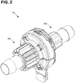
- aseptic coupling devices 100 and 200 are shown in a pre-coupled state. In this state, the aseptic coupling device 100 is received into a portion of aseptic coupling device 200. However, a sterile flow path has not yet been created because membranes associated with the aseptic coupling devices 100, 200 have not yet been removed.
- aseptic coupling device 100 is a male coupling device
- aseptic coupling device 200 is a female coupling device
- device 100 may be referred to as male coupling device 100
- device 200 may be referred to as female coupling device 200.
- the concepts presented herein are not limited to only those embodiments where coupling device 100 is a male coupling device and where coupling device 200 is a female coupling device.
- the devices 100, 200 are keyed so that the devices 100, 200 can only be coupled in one manner, as described below. In alternative embodiments, other configurations are possible.
- the male aseptic coupling device 100 includes a main body 102, a membrane 104, a ring adapter 106, a locking ring 108, a sealing member 109, and a removable cover 300.
- the main body 102 has a first open end 112 and a second open end 114 through which a fluid passage 116 is defined.
- the main body 102 defines a first, second, and third internal diameter D.sub.1, D.sub.2, and D.sub.3 along fluid passage 116.
- the third diameter D.sub.3 is provided at a dimension that is sufficient to allow for insertion into a conduit (i.e. pathway 22), such as a hose or tube, having a nominal internal diameter.
- the second diameter D.sub.2 is provided at a dimension that is generally about the same as the nominal internal diameter of the conduit to which the main body 102 is designed for connection.
- D.sub.3 When D.sub.3 is provided at a sufficient dimension, D.sub.2 can be designed to provide a 2.5 cm (1 inch) flow. In one embodiment, the third diameter D.sub.3 is provided at a dimension that is generally about the same as or slightly less than the external diameter of sealing member 109. At a location where the first and second internal diameters D.sub.1, D.sub.2 adjoin, a seal seat 138 is formed for supporting and forming a seal with sealing member 109.
- Sealing member 109 is shown in further detail at FIGS. 19-21 .
- the seal seat 138 is located a distance L.sub.1 from a first 10 face 118 of the main body 102.
- Sealing member 109 has a thickness L.sub.2 that is slightly greater than L.sub.1 to ensure that the sealing member 109 makes sufficient contact with the corresponding sealing member 209 in the main body 202 and seal seat 138 to form an aseptic seal.
- Sealing member 109 also has an internal diameter D.sub.4 that is about the same dimension as second diameter D.sub.2.
- Sealing member 109 also has an external diameter D.sub.5 that is about the same dimension as first diameter D.sub.1. Sealing member 109 also has a sidewall S that has a reduced thickness at the midpoint of the sidewall S. This structure enhances the axial compression performance of the sealing member 109 while ensuring that flow through the sealing member 109 is not restricted by the unintended formation of an inwardly extending bulge under compression. This structure also provides for enhanced sealing when the system is pressurized.
- diameter D.sub.1 is about 3.8 cm (1.5 inch), for example 3.78 cm 1.49 inch); diameter D.sub.2 is about 2.5 cm (1 inch), for example 2.64 cm (1.04 inch); diameter D.sub.3 is about 2.5 cm (1 inch), for example 2.3 cm (0.92 inch); diameter D.sub.4 is about 2.5 cm (1 inch), for example 2.6 cm (1.02 inch); diameter D.sub.5 is about 3.8 cm (1.5 inch), for example 3.81 cm (1.50 inch); length L.sub.1 is about 1.5 cm (0.6 inch), for example 1.49 cm (0.59 inch); length L.sub.2 is about 1.5 cm (0.6 inch), for example 1.57 cm (0.62 inch); and the nominal internal diameter of the pathway 22 is about 2.5 cm (1 inch), for example 2.54 cm (1.0 inch). These dimensions are generally applicable for a 2.5 cm (1 inch) nominal termination. One skilled in the art will appreciate that other dimensions are possible, for example where the nominal termination is 1.9 cm (3 ⁇ 4 inch) or 3.8 cm (1 1 ⁇ 2 inch).
- the first end 112 of the main body 102 is the end which interfaces with the female coupling device 200. As shown, the first end 112 includes a first face 118 and a second face 120 that are spaced from each other by a plurality of ribs 122. The first face 118 and ribs 122 provide structure for ensuring aligned engagement with the female coupling device 200.
- the first face 118 and ribs 122 also include features to prevent the main body 102 of the male coupling device 100 from rotating with respect to the main body 202 of the female coupling device 200 once the main body 102 is received into the female coupling device 200. In part, this is accomplished by a first alignment feature 124 that is configured to align with a corresponding alignment feature 214 on the main body 202. When main bodies 102, 202 are aligned together by the alignment features 124, 214, the alignment feature 124 is disposed between first and second securing arms 210, discussed later, on the main body 202 which prevent the main bodies 102, 202 from rotating with respect to each other.
- a further visual indication of alignment is provided by the alignment of protrusions 124a and 214a on alignment features 124 and 214, respectively.
- Tabs 126 are also provided on the first face 118 that engage an end opposite alignment feature 124 on the securing arms 210 that further prevent the main bodies 102, 202 from being able to rotate with respect to each other.
- a rib122 is also provided at each tab 126 to provide further engaging structure.
- two securing arms 210 and three alignment features are shown, one skilled in the art, upon learning of the disclosed concepts presented herein, will appreciate that other numbers and configurations of alignment features and securing arms may be utilized to achieve the same positioning and anti-rotation functions.
- the first face 118 of main body 102 and the securing arms 210 are also complementarily shaped to ensure that the first face 118 of main body 102 and a first face 208 of the main body 202 can be engaged together only in a single orientation and only by movement along the longitudinal axis X of the bodies 102, 202. This arrangement prevents a user from sliding the faces 118 and 208 against each other and potentially damaging the aseptic seal provided by the membranes 104, 204, discussed later, attached to each coupling device 100, 200.
- the first face 118 of the main body 102 further includes a pair of stand-off protrusions 128 configured to engage a corresponding pair of stand-off protrusions 216 on the first face 208 of main body 202 of the female coupling device 200.
- the stand-off protrusions 128, 216 ensure that the first faces 118, 208 have a clearance between them and do not fully compress against each other when the coupling devices 100, 200 are placed in a coupled state. As configured, stand-off protrusions 128, 216 help to stabilize the connection to reduce the possibility of side load induced leakage.
- stand-off protrusions 128, 216 help to stabilize the connection to reduce the possibility of side load induced leakage.
- the first face 118 also includes surface locations 130a, 130b to allow for membrane 104 to be attached to the front face.
- the surface locations 130a, 130b are provided with an adhesive to which the membrane is adhered.
- the adhesive can be provided on the membrane 104 which can be subsequently attached to surface locations 130a, 130b.
- the membrane 104 is heat welded to the first face 118. In such an embodiment, surface locations 130a, 130b are not necessarily required.
- connection feature 132 is barbed to form a hose barb (HB) type connection so that the main body 102 can be connected to a fluid pathway (e.g., 22) such as a tube or hose of a specified diameter, for example 3 ⁇ 4", 1", and 11 ⁇ 2".
- a fluid pathway e.g. 22
- a sanitary type connection feature may be provided.
- the main body 102 also includes a ridge member 134. Ridge member 134 and the second face 120 of the main body 102 are configured to retain the ring adapter 106, discussed later, such that the ring adapter 106 can rotate about the main body 102.
- the main body also includes a plurality of tabs 136 for guiding and indexing the rotation of the ring adapter 106.
- one of the tabs 136a has a length, extending in a direction parallel to the longitudinal axis X, sufficient to engage with a first indexing feature 150 and a second indexing feature 152 provided on the ring adapter 106.
- Tab 136a functions as a surface against which the indexing features 150 and 152 can snap against to provide rotational resistance and an audible click when the ring adapter 106 and locking ring 108 are rotated into and out of the indexed position and into the secured position, respectively.
- tabs 136 have a width, in a direction extending normal from the longitudinal axis X, sufficient to hold the ring adapter 106 aligned as the ring adapter is indexed into and out of indexing positions.
- four tabs 136 are provided on the main body 102 with one of the tabs 136 being an indexing tab 136a.
- more or less than four tabs 136 may be provided, any or all of which may be indexing tabs 136a.
- tabs 136 also act as stop members to prevent reverse rotation of the ring adapter 106 from the secured position back towards the initial indexed position by engagement with locking feature 154 provided on the ring adapter 106.
- ring adapter 106 is formed from two identical ring adapter halves 106a that mate together about main body 102. Mating of the adapter halves 106a is facilitated by edge projections 140, 142 provided at the edge of each half 106a. Edge projection 140 is complimentarily shaped to accept edge projection 142, thereby allowing the ring adapter halves 106a to mate together in a predetermined alignment.
- Each ring adapter half 106a has at least a first exterior portion 144 and a second exterior portion 146.
- the first exterior portion 144 serves as a support surface for the locking ring 108, discussed later.
- the second exterior portion 146 is provided with a plurality of fins that form a finned structure serving as a gripping feature for a user when rotating the ring adapter 106 and the locking ring 108 to which the ring adapter 106 is connected.
- the fins on the second exterior portion can be sized large enough to allow for a user to have enough leverage to rotate the ring adapter 106 without requiring the application of excessive force.
- the ring adapter 106 has a first indexing feature 150 that is configured to index with the indexing tab 136 on the main body 102.
- each adapter ring half 106a has a first indexing feature 150 comprising a pair of protrusions 150a.
- the indexing tab 136 is between the protrusions 150a, the ring adapter 106 is in an indexed position.
- a rotating force on the ring adapter 106 a user can cause the ring adapter to rotate into and out of the indexing position. Rotating the ring adapter 106 into or out of the indexing position can be felt by the user in the form of rotational resistance, and can also be heard as an audible clicking sound.
- each ring adapter half 106a is shown with a first indexing feature 150
- the assembled ring adapter 106 has two indexing positions.
- the main body 102 is shown as having a single indexing tab 136a, two indexing positions for the coupling 100 result that are separated by 180 degrees of rotation.
- the number and degree separation of the indexing positions can be altered by changing the number and/or location of the indexing tabs and the indexing features.
- Each ring adapter half 106a is also provided with a second indexing feature 152 having a pair of protrusions 152a that operate in the same manner as protrusions 150a.
- second indexing feature 152 is offset from first indexing feature 150 by about 90 degrees and corresponds to the secured position.
- a locking feature 154 is also provided on each ring adapter half 106a.
- the locking feature 154 engages with the tabs 136 on the main body 102 to prevent the ring adapter 106 from rotating in a reverse direction once rotated into the secured position. This is accomplished by providing a ramped surface 154a and a locking surface 154b. As the ring adapter 106 is rotated out of the indexed position and towards the secured position, the ramped surface 154a engages tab 136. As rotation continues, the locking feature 154 is deflected outwards and the ramped surface 154a therefore causes rotational resistance. As rotation further continues, the ramped surface 154a moves past tab 136 and is no longer engaged with tab 136.
- the locking surface 154b will engage with the tab if reverse rotation is attempted, thereby locking the ring adapter 106 in the secured position.
- a locking feature 154b is provided on each ring adapter half 106a, the above described operation occurs at two locations simultaneously. It is noted that fewer or more locking features 154 may be provided on ring adapter 106. In the embodiment shown with four tabs 136 and two locking features 154b, it is additionally noted that the locking surfaces 154b prevent reverse rotation of the ring adapter 106 from the initially indexed position and from the secured position by engagement with tabs 136.
- the ring adapter 106 is connected to the locking ring 108 via a plurality of retaining clips 148 extending through corresponding apertures 160 in the locking ring 108.
- retaining clips 148 and four corresponding apertures 160 are provided.
- the retaining clips 148 and apertures 160 are provided in an asymmetrically spaced pattern.
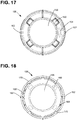
- locking ring 108 is shown in further detail at Figures 15-18 .
- locking ring 108 includes a plurality of apertures 160 for receiving the retaining clips 148 on the ring adapter 106.
- Locking ring defines a central aperture 166 through which the ring adapter 106 and main body 102 extend.
- Locking ring 108 also includes two alignment indicators 162 for ensuring that the locking ring 108 is properly aligned with the alignment protrusion 124a on the main body 102 before the main bodies 102, 202 are coupled together.
- the locking ring 108 also includes indicia 164 for showing the proper direction of rotation for the locking ring 108 to lock the ring onto body 202.
- the indicia 164 includes the word "start.”
- the locking ring 108 further includes stop members 170 for preventing the locking ring 108 from rotating in the reverse direction from the initial starting position.
- locking feature 154b also performs this function. As such, embodiments including only one or both of these features are possible without departing from the concepts disclosed herein.
- the locking ring 108 includes a pair of ramp surfaces 168.
- Ramp surfaces 168 are for engaging corresponding ramp surfaces 218 on the main body 202 of the female coupling device 200.
- ramp surfaces 168 and 218 pull the main bodies 102, 202 towards each other and force a seal between sealing members 109 and 209.
- the locking ring has rotated to ensure that a sufficient compressive force exists to form a seal between the sealing members 109, 209, but not so much so that the membranes 104, 204 separating the sealing members 109, 209 cannot be removed.
- indexing feature 152 and locking feature 154 are not present on the ring adapter half and are replaced by locking features 172, located on the locking ring 108.
- the locking features 172 form ramped surfaces beyond which reverse rotation is prevented.
- the lock features 172 engage a side edge 224a of stop surface 224 attached to each securing arm 210, when rotated to the secured position. Once engaged in this position, the locking ring 108 is prevented from moving in the reverse direction by the lock features 172.
- ramped surfaces or other types of locking features may be used, or that ramped surfaces could be provided on only the main body 202 of the female coupling device 200 or only the locking ring 108.
- the lock features 172 can be removed.
- membrane 104 is coupled to the first face 118 of the aseptic coupling device 100.
- the membrane is coupled to the first face 118 completely around and beyond the first open end 112 of the main body 102 at attachment locations 130a, 130b.
- the attachment locations 130 allow membrane 104 to extend beyond the opening in the open end 112 so that as membrane 104 is removed, the sterility of open end 112 is maintained even if membranes 104, 204 are pulled at different rates.
- membranes 104, 204 Prior to coupling the coupling devices 100, 200 together, membranes 104, 204 are folded over their respective front faces 118, 208 such that each membrane will roll on itself and detach from the front face as it is pulled out of the aseptic coupling arrangement 50.
- handles 182, 232 are provided at the ends 180, 230 of membranes 104, 204, respectively.
- the handles 182, 232 are connected to each other by attachment members 184, 234. Once attached, a single handle is formed that can be pulled by an operator with the assurance that the membranes 104, 204 will be removed in simultaneous or near simultaneous fashion. However, the membranes can be removed in sequential fashion as well, although sterility may be compromised.
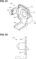
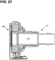
- cover 300 for the first aseptic coupling 100 is shown.
- cover 300 includes a pair of retaining arms 302 with retaining clips 304 for engaging the locking ring 108.
- Cover 300 further includes a sidewall 306 that surrounds a majority of the front face 118 of the main body 102.
- a channel 308 is also provided to hold the membrane 104 in a secure position.
- Cover 300 is also shown as including a raised surface 310 for aiding in retaining the sealing member 109 and the membrane 104 in a secure position.
- An additional raised surface 312 is provided to further retain the membrane 104 above the seal at general area of the upper attachment location 130b.
- Figures 25-27 show the cover 300 mounted onto the first aseptic coupling device 100.
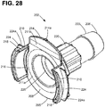
- the second aseptic coupling device 200 is shown in further detail.
- the aseptic coupling device 200 has a main body 202 including securing legs 210 having ramp surfaces 218 and stop surfaces 224 and including an alignment feature 214.
- Main body 202 also has a first open end 205 and a second open end 206 through which a fluid passage 228 is defined.
- the main body 202 defines a first, second, and third internal diameter D.sub.11, D.sub.12, and D.sub.13 along fluid passage 228.
- the diameter D.sub.13 is provided at a dimension sufficient to allow for insertion of the second end 206 into a conduit (i.e. pathway 32), such as a hose or tube having a nominal internal diameter.
- the diameter D.sub.12 is provided at a dimension that is generally about the same as the nominal internal diameter of the conduit to which the main body 202 is designed for connection. In one embodiment, D.sub.12 is sufficiently sized to provide 2.5 cm (1 inch) flow given that D.sub.13 is sufficiently sized.
- the diameter D.sub.11 is provided at a dimension that is generally about the same as or slightly less than the external diameter of sealing member 209. At a location where the diameters D.sub.11 and D.sub.12 adjoin, a seal seat 226 is formed for supporting and forming a seal with sealing member 109.
- Sealing member 209 is the same as that shown for sealing member 109 in FIGS. 19-21 .
- the seal seat 226 is located a distance L.sub.1 from a first face 208 of the main body 202.
- Sealing member 209 has a thickness L.sub.2 that is slightly greater than L.sub.1 to ensure that the sealing member 209 makes sufficient contact with the corresponding sealing member 109 in the main body 102 and the seal seat 226 to form an aseptic seal.
- Sealing member 209 also has an internal diameter D.sub.4 that is about the same dimension as second diameter D.sub.12.
- Sealing member 209 also has an external diameter D.sub.5 that is about the same dimension as first diameter D.sub.11.
- Sealing member 209 also has a sidewall S that has a reduced thickness at the midpoint of the sidewall S. This structure enhances the axial compression performance of the sealing member 209 while ensuring that flow through the sealing member 209 is not restricted by the unintended formation of an inwardly extending bulge during compression. As stated previously, the pressurized fluid acting on the seal structure also enhances the sealing characteristics of the seal.
- diameter D.sub.11 is about 3.8 cm (1.5 inch), for example 3.78 (1.49 inch); diameter D.sub.12 is about 2.5 cm (1 inch), for example 2.64 cm (1.04 inch); diameter D.sub.13 is about 2.5 cm (1 inch), for example 2.3 cm (0.
- diameter D.sub.4 is about 2.5 cm (1 inch), for example 2.6 cm (1.02 inch); diameter D.sub.5 is about 3.8 cm (1.5 inch), for example 3.81 cm (1.50 inch); length L.sub.1 is about 1.5 cm (0.6 inch), for example 1.49 cm (0.59 inch); length L.sub.2 is about 1.5 cm (0.6 inch), for example 1.57 cm (0.62 inch); and the nominal internal diameter of the pathway 32 is about 2.5 cm (1 inch), for example 2.54 cm (1.0 inch).
- the first face 208 of the main body also includes surface locations 211a, 211b to allow for membrane 204 to be attached to the front face 208.
- the surface locations 211a, 211b are provided with an adhesive to which the membrane is adhered.
- the adhesive can be provided on the membrane 204 which can be subsequently attached to surface locations 211a, 211b.
- the membrane 204 is heat welded (or heat staked) to the front face 208. In such an embodiment, surface locations 211a, 211b are not necessarily required.
- Main body 202 further comprises an exterior portion 220 that is provided with a fluted surface and serves as a gripping member for a user when rotating the ring adapter 106 and the locking ring 108 with respect to the main body 202.
- connection feature 222 is barbed so that the main body 202 can be connected to a fluid pathway (e.g., 32) such as a hose of a specified diameter, for example 3 ⁇ 4", 1", and 11 ⁇ 2".
- a fluid pathway e.g. 32
- a sanitary type connection feature may be provided.
- cover 400 for the first aseptic coupling 200 is shown.
- cover 400 includes a pair of retaining arms 402 with retaining clips 404 for engaging the stop surfaces 224 of the main body 202.
- Cover 400 further includes a sidewall 406 that engages a portion of the securing legs 210 of the main body 202.
- a channel 408 is also provided to hold the membrane 204 in a secure position.
- Cover 400 is also shown as including a raised surface 410 for aiding in retaining the sealing member 209 and the membrane 204 in a secure position.
- An additional raised surface 412 is provided to further retain the membrane 204 above the seal at general area of the upper attachment location 211b.
- Figures 35-37 show the cover 400 mounted onto the second aseptic coupling device 200.
- first face 118 of aseptic coupling device 100 is inserted into aseptic coupling device 200 along longitudinal axis X.
- securing arms 210 are received within the locking ring 108.
- ramp surfaces 218 are also received by the locking ring 108. In this position, aseptic coupling device 100 is in a pre-coupled state with respect to aseptic coupling device 200.
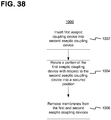
- a portion of the first aseptic coupling device is rotated with respect to the second aseptic coupling device into a secured position.
- the ramp surfaces 168, 218 are engaged by rotating the locking ring 108 with respect to the main bodies 102, 202. Once engaged, ramp surfaces 168, 218 pull aseptic coupling device 100 toward aseptic coupling device 200 to compress the sealing members 109, 209 together.
- the secured position can be obtained by rotating the ring adapter 106 until it is locked in place by the interaction of the locking feature(s) 154 and the tab(s) 136 and/or by lock members 172.
- membranes 104, 204 are removed from the first and second aseptic coupling devices to form a sterile connection.
- This step may include attaching the membrane handles 182 and 232 together and pulling them in a direction normal to and extending away from the longitudinal axis X of the aseptic coupling arrangement 50. Due to this action, membranes 104, 204 roll in on one another and are removed in a simultaneous or near simultaneous fashion. Subsequently, the sealing members 109, 209 of each of aseptic coupling devices 100, 200 engage with each other. Once this occurs, an aseptic pathway exists through passages 116, 228 of the aseptic coupling devices 100, 200. See Figure 5 .
- the protrusions 128, 216 may define the level of compression for the sealing members 109, 209 where the protrusions 128, 216 are drawn into contact with each other and prevent further compression of the sealing members 109, 209. It is also noted that step 1006 may also include removing the membranes one at a time in a sequential fashion although sterility may be compromised.
- step 1004a a portion of the first aseptic coupling device, such as the lock ring 108 and/or the ring adapter 106, is rotated with respect to the second aseptic coupling device into an intermediate position.
- the intermediate position may be a secured position in which reverse rotation is not possible or a non-secured position in which reverse rotation may occur.
- the intermediate position is a position in which the seals 109, 209 are compressed sufficiently to form a seal with each other, but not compressed such that the membranes 104, 204 cannot be removed.
- the secured position of step 1004 may be of greater compressive force than that applied in the intermediate step 1004a. In one embodiment, the compressive force in the secured position is of a magnitude that the membranes 102, 204 could not be removed with such a force present.
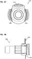
- FIG. 40-48 another example aseptic coupling arrangement 1200 including a first aseptic coupling device 1210 and a second aseptic coupling device 1220 is shown.
- the aseptic coupling arrangement 1200 is similar to the aseptic coupling arrangement 50 described above, with the following noted exceptions.
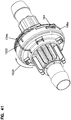
- a lock ring 108a of the first aseptic coupling device 1210 includes the indicia 164 illustrating the rotational start position of the lock ring 108a during coupling of the first aseptic coupling device 1210 to the second aseptic coupling device 1220.
- the indicia 164 lines up with the alignment protrusion 124a on the second aseptic coupling device 1220.
- the lock ring 108a also includes indicia 1221 and 1222 formed on opposing sides of the lock ring 108a.
- indicia 1221 lines up with the alignment protrusion 124a to provide a visual indication of the pre-coupled state.
- An audible indication can also be provided.
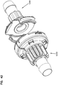
- the indicia 1222 lines up with the alignment protrusion 124a to provide a visual indication of the coupled state. See Figure 41 .
- An audible indication can also be provided.
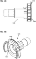
- the aseptic coupling arrangement 1200 also includes handles 1250, 1252 that are connected to each other in a manner similar to that described above for handles 182, 232. Once attached, a single handle is formed that can be pulled by an operator with the assurance that the membranes 104, 204 will be removed in simultaneous or near simultaneous fashion.
- each of the handles 1250, 1252 forms an aperture 1254, 1256, respectively. The user can place a finger or other instrument through the apertures 1254, 1256 to aid in applying the consistent force necessary to pull the membranes 104, 204.
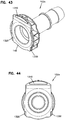
- the first face 118 of a main body 102a of the first aseptic coupling device 1210 includes protrusions 1310, 1320, 1330 formed on the first face 118. These protrusions 1310, 1320, 1330 are positioned to engage corresponding protrusions 1410, 1420, 1430 on a first face of the second aseptic coupling device 1220. See Figures 46-48 .
- a height of the protrusions 1301, 1320, 1330 and the protrusions 1410, 1420, 1430 is sized so that there is a slight gap between the protrusions 1301, 1320, 1330 and the protrusions 1410, 1420, 1430 when the aseptic coupling arrangement 1200 is in the pre-coupled state, and an even smaller gap therebetween when in the coupled state.
- any torque is applied to one or both of the first aseptic coupling device 1210 and the second aseptic coupling device 1220, one or more of the protrusions 1301, 1320, 1330 engage the protrusions 1410, 1420, 1430 to limit any rocking of the devices 1210, 1220 relative to one another.
- the aseptic coupling devices are coupled to one another and form a secure, sterile connection without requiring additional components to be added to make the connection.
- the aseptic coupling devices are coupled to one another without using external components to secure the connection.
- external components include secondary clamps.
- the aseptic coupling devices and their respective covers are made of a polymeric material.
- the aseptic coupling devices are made of polycarbonate and the sealing members used therein are made of a silicone rubber. Other materials can be used.
- membranes 104, 204 are autoclavable and gamma stable for sterilization.
- membranes 104, 204 are a composite design that consists of two components: 1 tag and 1 vent.
- the tag is a laminate including: a polyethylene terephthalate (PET) film, polyethylene (PE) foam, aluminum foil, and a sealing layer.
- PET polyethylene terephthalate
- PE polyethylene
- the foam and/or foil may or may not exist in the final configuration.
- the sealing layer allows the tag to be bonded or welded to polycarbonate connectors (e.g., aseptic coupling devices 100 and 200).
- the vent is an expanded polytetrafluoroethylene (ePTFE) membrane that will be bonded or welded onto the tag.
- Membranes 104, 204 are located over the center of the flow area of aseptic coupling devices 100 and 200, respectively, when the tags and vents are bonded or welded to connectors.
- the vent allows air and steam to flow into the system 10 during sterilization.
- the pore size of membranes 104, 204 are such that membranes 104, 204 filter out microorganisms larger than 0.2 microns.
- membranes 104, 204 are a polyethersulfone (PES) and polyester laminate membrane.
- PES polyethersulfone
- This membrane is hydrophobic and breathable.
- the pore size is such that microorganisms larger than 0.2 microns are filtered out.
- the polycarbonate melts into the polyester fibers, so that the PES acts as the filter, and the polyester acts as the structure.
- membranes 104, 204 are a Tyvek ® membrane (from DuPont) that is coated on one side to allow membranes 104, 204 to be bonded to polycarbonate connectors (e.g., aseptic coupling devices 100 and 200).
- Tyvek ® is breathable in nature, so there is no need for an additional vent.
- Tyvek ® is a non-woven polyethylene membrane.
Description
- Aseptic coupling devices can be used to connect two or more sterilized pathways. For example, aseptic coupling devices can be used to couple a fluid pathway from a first piece of processing equipment or container to a fluid pathway from a second piece of processing equipment or container to establish a sterile pathway for fluid transfer therebetween. Typical aseptic coupling devices require a "dry-to-dry" or "dry connection" that is created using one or more pathway clamping devices placed upstream of the aseptic coupling devices so that the aseptic coupling devices are kept free of fluid while the connection between the aseptic coupling devices is made. Once the sterile connection between the aseptic coupling devices is made, the clamping devices are removed to allow fluid to flow through the aseptic coupling devices.
-
US 2010/0230950 discloses the combination of features of the preamble of claim 1. It describes the formation of a sterile connection that includes inserting a first aseptic coupling device into a second aseptic coupling device, removing a first membrane from the first aseptic coupling device and a second membrane from the second aseptic coupling device, and rotating a locking clip on the first aseptic coupling device to compress a first seal member of the first aseptic coupling device with a second seal member of the second aseptic coupling device to form a sterile fluid passageway. -
US 2009/0232586 describes a sterile connector assembly for mounting on a fluid system includes a first connector and a second connector. The first connector includes a stem defining a fluid passage therethrough, a first housing surrounding the stem and defining a first aperture, and a first valve disposed over the first aperture. The second connector includes a second housing configured to matingly engage the first housing. The second housing defines a second aperture and defines a seal structure. The seal structure is configured to engage the stem. The second connector also includes a second valve disposed over the second aperture. The second valve is configured to engage the first valve when the first housing engages the second housing. -
US 2006/0192165 describes a connector assembly and a fluid system or device. -
US 3,909,910 describes a sterile connector for the end of a conduit employed in the passage of blood or of blood components. - The invention is defined in the claims.
- This disclosure relates to aseptic coupling devices and aseptic coupling arrangements. In accordance with the disclosure, a first aseptic coupling device for coupling to a second aseptic coupling device is provided.
- In one example, the first aseptic coupling device comprises a first main body defining a first face and a first fluid passage therethrough. The first aseptic coupling device can also include a first sealing member received at least partially within the first main body and a first membrane coupled to the first face of the first main body to cover the first sealing member. A ring adapter rotatable about the first main body and a locking ring coupled to the ring adapter can also be provided. The locking ring can be configured to couple the aseptic coupling device to the second aseptic coupling device. The first aseptic coupling device can also be provided with an indexing feature that indexes the rotational position of the locking ring to an indexed position on the first main body. The locking ring can also be configured to be rotatable from the initial indexed position to a secured position. The locking ring and/or the ring adapter may comprise at least one locking feature for preventing the locking ring and ring adapter from rotating from the secured position towards the initial indexed position when the aseptic coupling device is coupled to the second aseptic coupling device.
- In one example, the second aseptic coupling device comprises a second main body defining a second face and a second fluid passage therethrough. A second sealing member received at least partially within the second main body and a second membrane coupled to the second face to cover the second sealing member may also be provided. The second aseptic coupling device may also be provided with a stop surface configured to engage the stop member of the locking ring when the locking ring is in the secured position.
- In one example, an aseptic coupling arrangement includes the first and second aseptic coupling devices. The aseptic coupling arrangement can be configured such that a portion of the first aseptic coupling device can be received in the second aseptic coupling device to form a pre-coupled state only when the locking ring is in the indexed position. The aseptic coupling arrangement can be further configured such that the first and second aseptic coupling devices can be coupled together by rotating the locking ring from the initial indexed position to the secured position wherein a compressive force sufficient to press the first and second seals together to form a seal is provided while still allowing for the first and second membranes to be removable from the first and second coupling devices. The rotation may also include an intermediate position between the initial indexed position and the secured position in which the membranes are removable while the seals are sufficiently compressed to form an initial seal. In such an embodiment, the lock ring and retaining ring can be rotated to the secured position from the intermediate position after the membranes have been removed.
- A method for forming a sterile connection is also disclosed. The method may include the step of inserting a first aseptic coupling device into a second aseptic coupling device and the step of rotating a locking ring of the first aseptic coupling device into a secured position from an initially indexed position whereby the first and second aseptic coupling devices are in a coupled state. Another step in the method can be moving the locking ring and/or retaining ring into the secured position such that the locking ring and retaining ring are prevented from rotating back towards the initial indexed position. The method may also include the step of removing a first membrane from the first aseptic coupling device and removing a second membrane from the second aseptic coupling device. The removal of the membranes may be simultaneous or near simultaneous, or in some applications sequential. After removal of the membranes a sterile fluid passageway is formed. In another step, the locking ring may be rotated into an intermediate position prior to the step of removing the first and second membranes.
- Non-limiting and non-exhaustive embodiments are described with reference to the following figures, which are not necessarily drawn to scale, wherein like reference numerals refer to like parts throughout the various views unless otherwise specified.
-
Figure 1 is a schematic view of an example system including first and second pieces of processing equipment and an aseptic coupling device forming a sterile connection therebetween. -
Figure 2 is a perspective view of an example aseptic coupling arrangement in a pre-coupled state. -
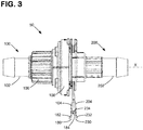
Figure 3 is a side view of the aseptic coupling arrangement ofFigure 2 . -
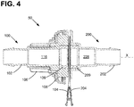
Figure 4 is a cross-sectional view of the aseptic coupling arrangement ofFigure 3 . -
Figure 5 is a cross-sectional view of the aseptic coupling arrangement ofFigure 2 in a coupled state. -
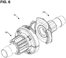
Figure 6 is a perspective view of the aseptic coupling arrangement ofFigure 2 in an uncoupled state. -
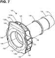
Figure 7 is a perspective view of a main body of the male aseptic coupling ofFigure 2 . -
Figure 8 is a side view of the main body ofFigure 7 . -
Figure 9 is an end view of the main body ofFigure 7 . -
Figure 10 is a cross-sectional view of the main body ofFigure 7 . -
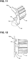
Figure 11 is a perspective view of a ring adapter half of the male aseptic coupling ofFigure 2 . -
Figure 12 is a first side view of the ring adapter half ofFigure 11 . -
Figure 13 is a second side view of the ring adapter half ofFigure 11 . -
Figure 13A is a side view of a second embodiment of a ring adapter half. -
Figure 14 is an end view of the ring adapter half ofFigure 11 . -
Figure 14A is an end view of a second embodiment of a ring adapter half. -
Figure 15 is a perspective view of a locking ring of the male aseptic coupling ofFigure 2 . -
Figure 16 is a side view of the locking ring ofFigure 15 . -
Figure 16A is a side view of a second embodiment of a locking ring. -
Figure 17 is a first end view of the locking ring ofFigure 15 . -
Figure 18 is a second end view of the locking ring ofFigure 15 . -
Figure 18A is an end view of a second embodiment of a locking ring. -
Figure. 19 is a perspective view of a sealing member used on the male and female aseptic couplings ofFigure 2 . -
Figure 20 is a side view of the sealing member ofFigure 19 . -
Figure 21 is an end view of the sealing member ofFigure 19 . -
Figure 22 is a perspective view of a cover for the male aseptic coupling ofFigure 2 . -
Figure 23 is a side view of the cover ofFigure 26 . -
Figure 24 is an end view of the cover ofFigure 26 . -
Figure 25 is a perspective view of the cover ofFigure 22 , as installed on the male aseptic coupling ofFigure 2 . -
Figure 26 is a side view of the cover ofFigure 22 , as installed on the male aseptic coupling ofFigure 2 . -
Figure 27 is a cross-sectional side view of the cover ofFigure 22 , as installed on the male aseptic coupling ofFigure 2 . -
Figure 28 is a perspective view of a main body of the female aseptic coupling ofFigure 2 . -
Figure 29 is a side view of the main body ofFigure 28 . -
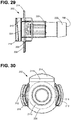
Figure 30 is an end view of the main body ofFigure 28 . -
Figure 31 is a cross-sectional side view of the main body ofFigure 28 . -
Figure 32 is a perspective view of a cover for the female aseptic coupling ofFigure 2 . -
Figure 33 is a side view of the cover ofFigure 32 . -
Figure 34 is an end view of the cover ofFigure 32 . -
Figure 35 is a perspective view of the cover ofFigure 32 , as installed on the female aseptic coupling ofFigure 2 . -
Figure 36 is a side view of the cover ofFigure 32 , as installed on the female aseptic coupling ofFigure 2 . -
Figure 37 is a cross-sectional side view of the cover ofFigure 32 , as installed on the female aseptic coupling ofFigure 2 . -
Figure 38 is a flow diagram of a method of creating an aseptic coupling of a first coupling device and a second aseptic coupling device. -
Figure 39 is a flow diagram of a method of creating an aseptic coupling of a first coupling device and a second aseptic coupling device. -
Figure 40 is a perspective view of another example aseptic coupling arrangement in a pre-coupled state. -
Figure 41 is a perspective view of the aseptic coupling arrangement ofFigure 40 in a coupled state. -
Figure 42 is a perspective view of the aseptic coupling arrangement ofFigure 40 in an uncoupled state. -
Figure 43 is a perspective view of a main body of the male aseptic coupling ofFigure 40 . -
Figure 44 is a front view of the main body ofFigure 43 . -
Figure 45 is a side view of the main body ofFigure 43 . -
Figure 46 is a perspective view of the female aseptic coupling ofFigure 40 . -
Figure 47 is a front view of the female aseptic coupling ofFigure 46 . -
Figure 48 is a side view of the female aseptic coupling ofFigure 46 . - Various embodiments will be described in detail with reference to the drawings, wherein like reference numerals represent like parts and assemblies throughout the several views. Reference to various embodiments does not limit the scope of the claims attached hereto. Additionally, any examples set forth in this specification are not intended to be limiting and merely set forth some of the many possible embodiments for the appended claims.
- As used herein, the term "sterilize" means a process of freeing, to a specified degree, a surface or volume from microorganisms. In example embodiments, the sterility of various components can be achieved using one or more sterilization techniques, including gamma irradiation, E-beam, ethylene oxide (EtO), and/or autoclave technologies.
- As used herein, the term "aseptic" refers to any process that maintains a sterilized surface or volume.
- As used herein, the term "fluid" means any substance that can be made to flow including, but is not limited to, liquids, gases, granular or powdered solids, mixtures or emulsions of two or more fluids, suspensions of solids within liquids or gases, etc.
- Referring now to
Figure 1 , anexample system 10 is shown.System 10 includes a first piece ofprocessing equipment 20 and a second piece ofprocessing equipment 30. In example embodiments,equipment equipment -
Equipment 20 includes afluid pathway 22 extending therefrom that is terminated by anaseptic coupling arrangement 50 including a firstaseptic coupling device 100. Likewise,equipment 30 includes afluid pathway 32 extending therefrom that is terminated by a secondaseptic coupling device 200 of theaseptic coupling arrangement 50. In example embodiments, the environment withinpathways aseptic coupling devices -
Aseptic coupling device 100 can be connected toaseptic coupling device 200. Onceaseptic coupling device 100 is connected toaseptic coupling device 200, a sterile fluid pathway is established betweenequipment 20 andequipment 30. Once the sterile fluid pathway is established, fluid can be transferred fromequipment 20 toequipment 30, or vice versa. - Referring now to
Figures 1-2 ,aseptic coupling devices aseptic coupling device 100 is received into a portion ofaseptic coupling device 200. However, a sterile flow path has not yet been created because membranes associated with theaseptic coupling devices - In the example shown,
aseptic coupling device 100 is a male coupling device, andaseptic coupling device 200 is a female coupling device. For ease of reference,device 100 may be referred to asmale coupling device 100 anddevice 200 may be referred to asfemale coupling device 200. However, it should be understood that the concepts presented herein are not limited to only those embodiments wherecoupling device 100 is a male coupling device and wherecoupling device 200 is a female coupling device. In the example shown, thedevices devices - In the example shown, the male
aseptic coupling device 100 includes amain body 102, amembrane 104, aring adapter 106, alocking ring 108, a sealingmember 109, and aremovable cover 300. - As most easily viewed at
Figures 7-10 , themain body 102 has a firstopen end 112 and a secondopen end 114 through which afluid passage 116 is defined. As most easily seen atFigure 10 , themain body 102 defines a first, second, and third internal diameter D.sub.1, D.sub.2, and D.sub.3 alongfluid passage 116. The third diameter D.sub.3 is provided at a dimension that is sufficient to allow for insertion into a conduit (i.e. pathway 22), such as a hose or tube, having a nominal internal diameter. The second diameter D.sub.2 is provided at a dimension that is generally about the same as the nominal internal diameter of the conduit to which themain body 102 is designed for connection. When D.sub.3 is provided at a sufficient dimension, D.sub.2 can be designed to provide a 2.5 cm (1 inch) flow. In one embodiment, the third diameter D.sub.3 is provided at a dimension that is generally about the same as or slightly less than the external diameter of sealingmember 109. At a location where the first and second internal diameters D.sub.1, D.sub.2 adjoin, aseal seat 138 is formed for supporting and forming a seal with sealingmember 109. - Sealing
member 109 is shown in further detail atFIGS. 19-21 . In the embodiment shown, theseal seat 138 is located a distance L.sub.1 from a first 10face 118 of themain body 102. Sealingmember 109 has a thickness L.sub.2 that is slightly greater than L.sub.1 to ensure that the sealingmember 109 makes sufficient contact with the corresponding sealingmember 209 in themain body 202 and sealseat 138 to form an aseptic seal. Sealingmember 109 also has an internal diameter D.sub.4 that is about the same dimension as second diameter D.sub.2. - Sealing
member 109 also has an external diameter D.sub.5 that is about the same dimension as first diameter D.sub.1. Sealingmember 109 also has a sidewall S that has a reduced thickness at the midpoint of the sidewall S. This structure enhances the axial compression performance of the sealingmember 109 while ensuring that flow through the sealingmember 109 is not restricted by the unintended formation of an inwardly extending bulge under compression. This structure also provides for enhanced sealing when the system is pressurized. - In the exemplary embodiment shown, diameter D.sub.1 is about 3.8 cm (1.5 inch), for example 3.78 cm 1.49 inch); diameter D.sub.2 is about 2.5 cm (1 inch), for example 2.64 cm (1.04 inch); diameter D.sub.3 is about 2.5 cm (1 inch), for example 2.3 cm (0.92 inch); diameter D.sub.4 is about 2.5 cm (1 inch), for example 2.6 cm (1.02 inch); diameter D.sub.5 is about 3.8 cm (1.5 inch), for example 3.81 cm (1.50 inch); length L.sub.1 is about 1.5 cm (0.6 inch), for example 1.49 cm (0.59 inch); length L.sub.2 is about 1.5 cm (0.6 inch), for example 1.57 cm (0.62 inch); and the nominal internal diameter of the
pathway 22 is about 2.5 cm (1 inch), for example 2.54 cm (1.0 inch). These dimensions are generally applicable for a 2.5 cm (1 inch) nominal termination. One skilled in the art will appreciate that other dimensions are possible, for example where the nominal termination is 1.9 cm (¾ inch) or 3.8 cm (1 ½ inch). - The
first end 112 of themain body 102 is the end which interfaces with thefemale coupling device 200. As shown, thefirst end 112 includes afirst face 118 and asecond face 120 that are spaced from each other by a plurality ofribs 122. Thefirst face 118 andribs 122 provide structure for ensuring aligned engagement with thefemale coupling device 200. - The
first face 118 andribs 122 also include features to prevent themain body 102 of themale coupling device 100 from rotating with respect to themain body 202 of thefemale coupling device 200 once themain body 102 is received into thefemale coupling device 200. In part, this is accomplished by afirst alignment feature 124 that is configured to align with acorresponding alignment feature 214 on themain body 202. Whenmain bodies alignment feature 124 is disposed between first and second securingarms 210, discussed later, on themain body 202 which prevent themain bodies - A further visual indication of alignment is provided by the alignment of
protrusions first face 118 that engage an end oppositealignment feature 124 on the securingarms 210 that further prevent themain bodies - In the exemplary embodiment shown, a rib122 is also provided at each tab 126 to provide further engaging structure. Although two securing
arms 210 and three alignment features (feature 124 and tabs 126) are shown, one skilled in the art, upon learning of the disclosed concepts presented herein, will appreciate that other numbers and configurations of alignment features and securing arms may be utilized to achieve the same positioning and anti-rotation functions. - The
first face 118 ofmain body 102 and the securingarms 210 are also complementarily shaped to ensure that thefirst face 118 ofmain body 102 and afirst face 208 of themain body 202 can be engaged together only in a single orientation and only by movement along the longitudinal axis X of thebodies faces membranes coupling device - This arrangement also ensures that the
bodies coupling arms 210 andfirst face 118 are shown as having complementing curved shapes, one skilled in the art, upon learning of the disclosed concepts presented herein, will appreciate that other complementary shapes may be utilized to ensure the same aligned engagement function. - The
first face 118 of themain body 102 further includes a pair of stand-offprotrusions 128 configured to engage a corresponding pair of stand-offprotrusions 216 on thefirst face 208 ofmain body 202 of thefemale coupling device 200. The stand-offprotrusions coupling devices protrusions - The
first face 118 also includessurface locations membrane 104 to be attached to the front face. In one embodiment, thesurface locations membrane 104 which can be subsequently attached to surfacelocations membrane 104 is heat welded to thefirst face 118. In such an embodiment,surface locations - As shown, the
second end 114 of themain body 102 is configured to be connected to a fluid pathway via aconnection feature 132. In the example shown, theconnection feature 132 is barbed to form a hose barb (HB) type connection so that themain body 102 can be connected to a fluid pathway (e.g., 22) such as a tube or hose of a specified diameter, for example ¾", 1", and 1½". Instead of a barbed connection feature, a sanitary type connection feature may be provided. - The
main body 102 also includes aridge member 134.Ridge member 134 and thesecond face 120 of themain body 102 are configured to retain thering adapter 106, discussed later, such that thering adapter 106 can rotate about themain body 102. - The main body also includes a plurality of
tabs 136 for guiding and indexing the rotation of thering adapter 106. In the embodiment shown, one of thetabs 136a has a length, extending in a direction parallel to the longitudinal axis X, sufficient to engage with afirst indexing feature 150 and asecond indexing feature 152 provided on thering adapter 106.Tab 136a functions as a surface against which the indexing features 150 and 152 can snap against to provide rotational resistance and an audible click when thering adapter 106 and lockingring 108 are rotated into and out of the indexed position and into the secured position, respectively. - Additionally, all of the
tabs 136 have a width, in a direction extending normal from the longitudinal axis X, sufficient to hold thering adapter 106 aligned as the ring adapter is indexed into and out of indexing positions. In the embodiment shown, fourtabs 136 are provided on themain body 102 with one of thetabs 136 being anindexing tab 136a. However, more or less than fourtabs 136 may be provided, any or all of which may be indexingtabs 136a. Additionally,tabs 136 also act as stop members to prevent reverse rotation of thering adapter 106 from the secured position back towards the initial indexed position by engagement with lockingfeature 154 provided on thering adapter 106. With reference toFigures, 11-14 , further details of thering adapter 106 are shown. In the exemplary embodiment presented,ring adapter 106 is formed from two identicalring adapter halves 106a that mate together aboutmain body 102. Mating of theadapter halves 106a is facilitated byedge projections Edge projection 140 is complimentarily shaped to acceptedge projection 142, thereby allowing thering adapter halves 106a to mate together in a predetermined alignment. - Each
ring adapter half 106a has at least a firstexterior portion 144 and a secondexterior portion 146. The firstexterior portion 144 serves as a support surface for thelocking ring 108, discussed later. Thesecond exterior portion 146 is provided with a plurality of fins that form a finned structure serving as a gripping feature for a user when rotating thering adapter 106 and thelocking ring 108 to which thering adapter 106 is connected. The fins on the second exterior portion can be sized large enough to allow for a user to have enough leverage to rotate thering adapter 106 without requiring the application of excessive force. - As described previously, the
ring adapter 106 has afirst indexing feature 150 that is configured to index with theindexing tab 136 on themain body 102. As most easily seen atFigure 14 , eachadapter ring half 106a has afirst indexing feature 150 comprising a pair of protrusions 150a. When theindexing tab 136 is between theprotrusions 150a, thering adapter 106 is in an indexed position. By applying a rotating force on thering adapter 106, a user can cause the ring adapter to rotate into and out of the indexing position. Rotating thering adapter 106 into or out of the indexing position can be felt by the user in the form of rotational resistance, and can also be heard as an audible clicking sound. - As each
ring adapter half 106a is shown with afirst indexing feature 150, the assembledring adapter 106 has two indexing positions. As themain body 102 is shown as having asingle indexing tab 136a, two indexing positions for thecoupling 100 result that are separated by 180 degrees of rotation. The number and degree separation of the indexing positions can be altered by changing the number and/or location of the indexing tabs and the indexing features. - Each
ring adapter half 106a is also provided with asecond indexing feature 152 having a pair ofprotrusions 152a that operate in the same manner as protrusions 150a. In the embodiment shown,second indexing feature 152 is offset fromfirst indexing feature 150 by about 90 degrees and corresponds to the secured position. By applying a rotating force on thering adapter 106, a user can cause the ring adapter to rotate into the secured position. Rotating thering adapter 106 into the secured position can be felt by the user in the form of rotational resistance, and can also be heard as an audible clicking sound. - As stated previously, a
locking feature 154 is also provided on eachring adapter half 106a. Thelocking feature 154 engages with thetabs 136 on themain body 102 to prevent thering adapter 106 from rotating in a reverse direction once rotated into the secured position. This is accomplished by providing a rampedsurface 154a and alocking surface 154b. As thering adapter 106 is rotated out of the indexed position and towards the secured position, the rampedsurface 154a engagestab 136. As rotation continues, thelocking feature 154 is deflected outwards and the rampedsurface 154a therefore causes rotational resistance. As rotation further continues, the rampedsurface 154a movespast tab 136 and is no longer engaged withtab 136. Once rotation has occurred to this point, the lockingsurface 154b will engage with the tab if reverse rotation is attempted, thereby locking thering adapter 106 in the secured position. As alocking feature 154b is provided on eachring adapter half 106a, the above described operation occurs at two locations simultaneously. It is noted that fewer or more locking features 154 may be provided onring adapter 106. In the embodiment shown with fourtabs 136 and two lockingfeatures 154b, it is additionally noted that the locking surfaces 154b prevent reverse rotation of thering adapter 106 from the initially indexed position and from the secured position by engagement withtabs 136. - The
ring adapter 106 is connected to thelocking ring 108 via a plurality of retainingclips 148 extending throughcorresponding apertures 160 in thelocking ring 108. In the particular embodiment shown, four retainingclips 148 and fourcorresponding apertures 160 are provided. In order to ensure proper alignment between theindexing feature 150 of thering adapter 106 and the rampedsurfaces 168, discussed below, of thelocking ring 108, the retainingclips 148 andapertures 160 are provided in an asymmetrically spaced pattern. - The
locking ring 108 is shown in further detail atFigures 15-18 . As stated previously, lockingring 108 includes a plurality ofapertures 160 for receiving the retaining clips 148 on thering adapter 106. Locking ring defines acentral aperture 166 through which thering adapter 106 andmain body 102 extend. Lockingring 108 also includes twoalignment indicators 162 for ensuring that thelocking ring 108 is properly aligned with thealignment protrusion 124a on themain body 102 before themain bodies locking ring 108 also includesindicia 164 for showing the proper direction of rotation for thelocking ring 108 to lock the ring ontobody 202. In the embodiment shown, theindicia 164 includes the word "start." Thelocking ring 108 further includes stopmembers 170 for preventing thelocking ring 108 from rotating in the reverse direction from the initial starting position. As mentioned above, lockingfeature 154b also performs this function. As such, embodiments including only one or both of these features are possible without departing from the concepts disclosed herein. - As stated above, the
locking ring 108 includes a pair of ramp surfaces 168. Ramp surfaces 168 are for engaging corresponding ramp surfaces 218 on themain body 202 of thefemale coupling device 200. By rotating thelocking ring 108, ramp surfaces 168 and 218 pull themain bodies members members membranes members - Referring to
Figures 13A, 14A ,16A, and 18A an alternative embodiment of thering adapter half 106a and lockingring 108 are shown. In the embodiment shown,indexing feature 152 and lockingfeature 154 are not present on the ring adapter half and are replaced by lockingfeatures 172, located on thelocking ring 108. The locking features 172 form ramped surfaces beyond which reverse rotation is prevented. In such an embodiment, the lock features 172 engage aside edge 224a ofstop surface 224 attached to each securingarm 210, when rotated to the secured position. Once engaged in this position, thelocking ring 108 is prevented from moving in the reverse direction by the lock features 172. One skilled in the art, upon learning of the disclosed concepts herein, will appreciate that additional ramped surfaces or other types of locking features may be used, or that ramped surfaces could be provided on only themain body 202 of thefemale coupling device 200 or only thelocking ring 108. In other alternatives, the lock features 172 can be removed. - As stated previously,
membrane 104 is coupled to thefirst face 118 of theaseptic coupling device 100. In examples, the membrane is coupled to thefirst face 118 completely around and beyond the firstopen end 112 of themain body 102 atattachment locations membrane 104 to extend beyond the opening in theopen end 112 so that asmembrane 104 is removed, the sterility ofopen end 112 is maintained even ifmembranes - Prior to coupling the
coupling devices membranes aseptic coupling arrangement 50. To ensure that themembranes ends membranes handles attachment members membranes - With reference to
Figures 22-24 , acover 300 for the firstaseptic coupling 100 is shown. As shown,cover 300 includes a pair of retainingarms 302 with retainingclips 304 for engaging thelocking ring 108. Cover 300 further includes asidewall 306 that surrounds a majority of thefront face 118 of themain body 102. Achannel 308 is also provided to hold themembrane 104 in a secure position. Cover 300 is also shown as including a raisedsurface 310 for aiding in retaining the sealingmember 109 and themembrane 104 in a secure position. An additional raisedsurface 312 is provided to further retain themembrane 104 above the seal at general area of theupper attachment location 130b.Figures 25-27 show thecover 300 mounted onto the firstaseptic coupling device 100. - Referring to
Figures 28-31 , the secondaseptic coupling device 200 is shown in further detail. As mentioned previously, theaseptic coupling device 200 has amain body 202 including securinglegs 210 havingramp surfaces 218 and stopsurfaces 224 and including analignment feature 214.Main body 202 also has a firstopen end 205 and a secondopen end 206 through which afluid passage 228 is defined. - As most easily seen at
FIG. 31 , themain body 202 defines a first, second, and third internal diameter D.sub.11, D.sub.12, and D.sub.13 alongfluid passage 228. The diameter D.sub.13 is provided at a dimension sufficient to allow for insertion of thesecond end 206 into a conduit (i.e. pathway 32), such as a hose or tube having a nominal internal diameter. The diameter D.sub.12 is provided at a dimension that is generally about the same as the nominal internal diameter of the conduit to which themain body 202 is designed for connection. In one embodiment, D.sub.12 is sufficiently sized to provide 2.5 cm (1 inch) flow given that D.sub.13 is sufficiently sized. The diameter D.sub.11 is provided at a dimension that is generally about the same as or slightly less than the external diameter of sealingmember 209. At a location where the diameters D.sub.11 and D.sub.12 adjoin, aseal seat 226 is formed for supporting and forming a seal with sealingmember 109. - Sealing
member 209 is the same as that shown for sealingmember 109 inFIGS. 19-21 . In the embodiment shown, theseal seat 226 is located a distance L.sub.1 from afirst face 208 of themain body 202. Sealingmember 209 has a thickness L.sub.2 that is slightly greater than L.sub.1 to ensure that the sealingmember 209 makes sufficient contact with the corresponding sealingmember 109 in themain body 102 and theseal seat 226 to form an aseptic seal. Sealingmember 209 also has an internal diameter D.sub.4 that is about the same dimension as second diameter D.sub.12. Sealingmember 209 also has an external diameter D.sub.5 that is about the same dimension as first diameter D.sub.11. Sealingmember 209 also has a sidewall S that has a reduced thickness at the midpoint of the sidewall S. This structure enhances the axial compression performance of the sealingmember 209 while ensuring that flow through the sealingmember 209 is not restricted by the unintended formation of an inwardly extending bulge during compression. As stated previously, the pressurized fluid acting on the seal structure also enhances the sealing characteristics of the seal. - In the exemplary embodiment shown, diameter D.sub.11 is about 3.8 cm (1.5 inch), for example 3.78 (1.49 inch); diameter D.sub.12 is about 2.5 cm (1 inch), for example 2.64 cm (1.04 inch); diameter D.sub.13 is about 2.5 cm (1 inch), for example 2.3 cm (0. 92 inch); diameter D.sub.4 is about 2.5 cm (1 inch), for example 2.6 cm (1.02 inch); diameter D.sub.5 is about 3.8 cm (1.5 inch), for example 3.81 cm (1.50 inch); length L.sub.1 is about 1.5 cm (0.6 inch), for example 1.49 cm (0.59 inch); length L.sub.2 is about 1.5 cm (0.6 inch), for example 1.57 cm (0.62 inch); and the nominal internal diameter of the
pathway 32 is about 2.5 cm (1 inch), for example 2.54 cm (1.0 inch). One skilled in the art will appreciate that other dimensions are possible. - The
first face 208 of the main body also includessurface locations membrane 204 to be attached to thefront face 208. In one embodiment, thesurface locations membrane 204 which can be subsequently attached to surfacelocations membrane 204 is heat welded (or heat staked) to thefront face 208. In such an embodiment,surface locations -
Main body 202 further comprises anexterior portion 220 that is provided with a fluted surface and serves as a gripping member for a user when rotating thering adapter 106 and thelocking ring 108 with respect to themain body 202. - As shown, the
second end 206 of themain body 202 is configured to be connected to a fluid pathway via aconnection feature 222. In the example shown, theconnection feature 222 is barbed so that themain body 202 can be connected to a fluid pathway (e.g., 32) such as a hose of a specified diameter, for example ¾", 1", and 1½". Instead of a barbed connection feature, a sanitary type connection feature may be provided. - With reference to
Figures 32-34 , acover 400 for the firstaseptic coupling 200 is shown. As shown,cover 400 includes a pair of retainingarms 402 with retainingclips 404 for engaging the stop surfaces 224 of themain body 202. Cover 400 further includes asidewall 406 that engages a portion of the securinglegs 210 of themain body 202. Achannel 408 is also provided to hold themembrane 204 in a secure position. Cover 400 is also shown as including a raisedsurface 410 for aiding in retaining the sealingmember 209 and themembrane 204 in a secure position. An additional raisedsurface 412 is provided to further retain themembrane 204 above the seal at general area of theupper attachment location 211b.Figures 35-37 show thecover 400 mounted onto the secondaseptic coupling device 200. - Referring now to
Figure 38 , anexample method 1000 for connectingaseptic coupling device 100 toaseptic coupling device 200 is shown. - First, at
operation 1002,first face 118 ofaseptic coupling device 100 is inserted intoaseptic coupling device 200 along longitudinal axis X. During insertion, securingarms 210 are received within thelocking ring 108. Whenfront face 118 is fully inserted, ramp surfaces 218 are also received by the lockingring 108. In this position,aseptic coupling device 100 is in a pre-coupled state with respect toaseptic coupling device 200. - Next, at
operation 1004, a portion of the first aseptic coupling device is rotated with respect to the second aseptic coupling device into a secured position. In one embodiment, the ramp surfaces 168, 218 are engaged by rotating thelocking ring 108 with respect to themain bodies aseptic coupling device 100 towardaseptic coupling device 200 to compress the sealingmembers ring adapter 106 until it is locked in place by the interaction of the locking feature(s) 154 and the tab(s) 136 and/or bylock members 172. - At
step 1006,membranes aseptic coupling arrangement 50. Due to this action,membranes members aseptic coupling devices passages aseptic coupling devices Figure 5 . As noted above, theprotrusions members protrusions members step 1006 may also include removing the membranes one at a time in a sequential fashion although sterility may be compromised. - With reference to
Figure 39 ,process 1000 is shown with anadditional step 1004a. Instep 1004a, a portion of the first aseptic coupling device, such as thelock ring 108 and/or thering adapter 106, is rotated with respect to the second aseptic coupling device into an intermediate position. The intermediate position may be a secured position in which reverse rotation is not possible or a non-secured position in which reverse rotation may occur. The intermediate position is a position in which theseals membranes step 1004 may be of greater compressive force than that applied in theintermediate step 1004a. In one embodiment, the compressive force in the secured position is of a magnitude that themembranes - Referring now to
Figures 40-48 , another exampleaseptic coupling arrangement 1200 including a firstaseptic coupling device 1210 and a secondaseptic coupling device 1220 is shown. Theaseptic coupling arrangement 1200 is similar to theaseptic coupling arrangement 50 described above, with the following noted exceptions. - A
lock ring 108a of the firstaseptic coupling device 1210 includes theindicia 164 illustrating the rotational start position of thelock ring 108a during coupling of the firstaseptic coupling device 1210 to the secondaseptic coupling device 1220. Theindicia 164 lines up with thealignment protrusion 124a on the secondaseptic coupling device 1220. - The
lock ring 108a also includesindicia lock ring 108a. When thelock ring 108a is rotated clockwise (i.e., direction 1224) to the pre-coupled state, theindicia 1221 lines up with thealignment protrusion 124a to provide a visual indication of the pre-coupled state. An audible indication can also be provided. - Further, when the
lock ring 108a is further rotated in thedirection 1224 to the coupled state, theindicia 1222 lines up with thealignment protrusion 124a to provide a visual indication of the coupled state. SeeFigure 41 . An audible indication can also be provided. - The
aseptic coupling arrangement 1200 also includeshandles handles membranes handles aperture apertures membranes - Referring to
Figures 43-45 , thefirst face 118 of amain body 102a of the firstaseptic coupling device 1210 includesprotrusions first face 118. Theseprotrusions protrusions aseptic coupling device 1220. SeeFigures 46-48 . A height of theprotrusions protrusions protrusions protrusions aseptic coupling arrangement 1200 is in the pre-coupled state, and an even smaller gap therebetween when in the coupled state. However, if any torque is applied to one or both of the firstaseptic coupling device 1210 and the secondaseptic coupling device 1220, one or more of theprotrusions protrusions devices - In some of the examples provided herein, the aseptic coupling devices are coupled to one another and form a secure, sterile connection without requiring additional components to be added to make the connection. For example, the aseptic coupling devices are coupled to one another without using external components to secure the connection. Such external components include secondary clamps.
- In example embodiments, the aseptic coupling devices and their respective covers are made of a polymeric material. For example, in one embodiment, the aseptic coupling devices are made of polycarbonate and the sealing members used therein are made of a silicone rubber. Other materials can be used.
- In some embodiments,
membranes membranes aseptic coupling devices 100 and 200). - The vent is an expanded polytetrafluoroethylene (ePTFE) membrane that will be bonded or welded onto the tag.
Membranes aseptic coupling devices system 10 during sterilization. The pore size ofmembranes membranes - In another embodiment,
membranes - In other embodiments,
membranes membranes aseptic coupling devices 100 and 200). Tyvek® is breathable in nature, so there is no need for an additional vent. Tyvek® is a non-woven polyethylene membrane.
Claims (10)
- An aseptic coupling arrangement (1200) in which a first aseptic coupling device is to be coupled to a second aseptic coupling device for establishing a sterile connection, wherein:the first aseptic coupling device (100, 1210) comprises:a first main body (102) defining a first face and a first fluid passage therethrough;a first sealing member (109) received at least partially within the first main body;a first membrane (104) coupled to the first face and covering the first sealing member; anda locking ring (108) connected to a ring adapter and configured to couple the first aseptic coupling device to the second aseptic coupling device,an indexing feature (150, 152) that indexes a rotational position of the locking ring to an indexed position (136) on the first main body; andthe second aseptic coupling device (200, 1220) comprises:a second main body (202) defining a second face and a second fluid passage therethrough;a second sealing member (209) received at least partially within the second main body;a second membrane (204) coupled to the second face to cover the second sealing member,wherein the first and second aseptic coupling devices are configured to be coupled together by rotating the locking ring from the initial indexed position to a secured position; characterized by the locking ring being rotatable about the first main body from i) the initial indexed position in which a portion of the first aseptic device can be inserted in the second aseptic coupling device to ii) the secured position in which a compressive force is created that is sufficient to form a seal of the first sealing member with a mating second sealing member but to still allow the first and second membrane to be removed.
- The aseptic coupling arrangement of claim 1, wherein the portion of the first aseptic coupling device can be inserted in the second aseptic coupling device only while the locking ring is in the initial indexed position.
- The aseptic coupling arrangement of any one of claims 1-2, wherein the first membrane comprises a first handle (182, 1250) that defines an aperture (1254) .
- The aseptic coupling arrangement of any one of claims 1-3, further comprising first stand-off protrusions extending from the first face of the first aseptic coupling device that are configured to engage second stand-off protrusions extending from a second face of the second aseptic coupling device to limit movement between the first aseptic and the second aseptic coupling devices.
- The aseptic coupling arrangement of any one of claims 1-4, wherein the second aseptic coupling device further comprises:
at least one stop member (224) configured to engage the locking ring. - The aseptic coupling arrangement of claim 5, wherein the first membrane comprises a first handle on a first free end of the first membrane, wherein the second membrane comprises a second handle on a second free end of the second membrane, wherein the first handle and the second handle are coupleable, and wherein the first handle and the second handle each define an aperture.
- The aseptic coupling arrangement of any one of claims 5-6, further comprising first stand-off protrusions extending from the first face of the first aseptic coupling device that are configured to engage second stand-off protrusions extending from the second face of the second aseptic coupling device to limit movement between the first aseptic and the second aseptic coupling devices.
- The aseptic coupling arrangement of any one of claims 1-4, , wherein the second aseptic coupling device further comprises:second stand-off protrusions (216) on the second face to ensure that the first and second faces (118, 208) have a clearance between them when the first aseptic and the second aseptic coupling devices are placed in a coupled state;two or more securing legs (210) extending from the second face;a ramp surface (218) extending from each of the securing legs; anda stop surface (224) extending from each of the securing legs and configured to engage with a locking ring of the first aseptic coupling device.
- The aseptic coupling arrangement of claim 8, wherein the first membrane comprises a first handle (182, 1250) on a first free end of the first membrane, wherein the second membrane comprises a second handle (232, 1252) on a second free end of the second membrane, wherein the first handle and the second handle are coupleable, and wherein the first handle and the second handle each define an aperture (1254, 1256).
- The aseptic coupling arrangement of any one of claims 8-9, further comprising a cover (400), the cover including a pair of retaining arms (402) that each includes a retaining clip (404) engageable with a respective one of the stop surfaces (224) of the second main body (202).
Applications Claiming Priority (3)
| Application Number | Priority Date | Filing Date | Title |
|---|---|---|---|
| US201261598986P | 2012-02-15 | 2012-02-15 | |
| PCT/US2013/026374 WO2013123347A1 (en) | 2012-02-15 | 2013-02-15 | Aseptic coupling devices |
| EP13707755.8A EP2814561B1 (en) | 2012-02-15 | 2013-02-15 | Aseptic coupling devices |
Related Parent Applications (2)
| Application Number | Title | Priority Date | Filing Date |
|---|---|---|---|
| EP13707755.8A Division EP2814561B1 (en) | 2012-02-15 | 2013-02-15 | Aseptic coupling devices |
| EP13707755.8A Division-Into EP2814561B1 (en) | 2012-02-15 | 2013-02-15 | Aseptic coupling devices |
Publications (2)
| Publication Number | Publication Date |
|---|---|
| EP3342450A1 EP3342450A1 (en) | 2018-07-04 |
| EP3342450B1 true EP3342450B1 (en) | 2021-12-15 |
Family
ID=47827443
Family Applications (2)
| Application Number | Title | Priority Date | Filing Date |
|---|---|---|---|
| EP18157865.9A Active EP3342450B1 (en) | 2012-02-15 | 2013-02-15 | Aseptic coupling devices |
| EP13707755.8A Active EP2814561B1 (en) | 2012-02-15 | 2013-02-15 | Aseptic coupling devices |
Family Applications After (1)
| Application Number | Title | Priority Date | Filing Date |
|---|---|---|---|
| EP13707755.8A Active EP2814561B1 (en) | 2012-02-15 | 2013-02-15 | Aseptic coupling devices |
Country Status (5)
| Country | Link |
|---|---|
| US (3) | US9726308B2 (en) |
| EP (2) | EP3342450B1 (en) |
| CN (2) | CN107261318B (en) |
| IN (1) | IN2014DN07554A (en) |
| WO (1) | WO2013123347A1 (en) |
Families Citing this family (27)
| Publication number | Priority date | Publication date | Assignee | Title |
|---|---|---|---|---|
| EP2409067B1 (en) * | 2009-03-16 | 2019-12-11 | Colder Products Company | Aseptic coupling devices |
| US9433725B2 (en) | 2011-12-23 | 2016-09-06 | Alcon Research, Ltd. | Combined coaxial and bimanual irrigation/aspiration apparatus |
| PT2986331T (en) | 2013-06-06 | 2019-02-01 | Novartis Ag | Transformer irrigation/aspiration device |
| WO2015013188A1 (en) * | 2013-07-23 | 2015-01-29 | Colder Products Company | Aseptic coupling devices |
| US9752714B2 (en) | 2014-03-28 | 2017-09-05 | Eldon James Corp. | Releasable valved coupler |
| US9346578B2 (en) | 2014-05-30 | 2016-05-24 | Finesse Solutions, Inc. | Aseptic connectors for bio-processing containers |
| SG10201806210SA (en) | 2014-05-30 | 2018-08-30 | Finesse Solutions Inc | Aseptic connectors for bio-processing containers |
| US9851037B2 (en) | 2014-08-20 | 2017-12-26 | Nordson Corporation | Fluid connector and method for making sealed fluid connections |
| JPWO2016072009A1 (en) * | 2014-11-07 | 2017-08-03 | 株式会社日立ハイテクノロジーズ | Aseptic connector and cell culture apparatus having the same |
| EP3405714A4 (en) | 2016-01-19 | 2019-10-16 | WilMarc Holdings, LLC | Connector system for releasably connecting fluid conduits |
| US10247342B2 (en) * | 2016-03-30 | 2019-04-02 | Pall Corporation | Connector assemblies, fluid systems including connector assemblies, and procedures for making fluid connections |
| EP3464981A4 (en) * | 2016-06-01 | 2020-03-18 | Jerry Shevitz | Device for aseptically connecting large bore tubing |
| JP6819900B2 (en) * | 2016-09-28 | 2021-01-27 | 株式会社ジェイ・エム・エス | Female connector |
| US10350401B2 (en) | 2017-03-08 | 2019-07-16 | Wilmarc Holdings, Llc | Catch assembly for releasably connecting fluid conduits |
| US11633584B2 (en) * | 2017-09-20 | 2023-04-25 | Miltenyi Biotec Gmbh | Sterile connector |
| CN109999333A (en) * | 2019-04-24 | 2019-07-12 | 华道(上海)生物医药有限公司 | Sterile docking adapter |
| CN114585411A (en) * | 2019-08-27 | 2022-06-03 | 考尔得产品公司 | Disposable asexual sterile fluid coupling |
| US11415255B1 (en) * | 2020-03-31 | 2022-08-16 | Colder Products Company | Aseptic fluid couplings |
| WO2022047023A1 (en) * | 2020-08-27 | 2022-03-03 | Colder Products Company | Fluid couplings |
| EP4264582A1 (en) | 2020-12-16 | 2023-10-25 | Fresh Blends Ltd | Smart inventory management system for a dispensing and blend-in-cup beverage platform |
| EP4288686A1 (en) * | 2021-02-08 | 2023-12-13 | Colder Products Company | Fluid couplings |
| CN117529348A (en) * | 2021-05-27 | 2024-02-06 | 恩特格里斯公司 | Sterile coupling assembly and sterile coupling method |
| US20230121701A1 (en) * | 2021-10-18 | 2023-04-20 | Colder Products Company | Fluid couplings |
| CN113996426B (en) * | 2021-10-21 | 2023-03-14 | 山东鑫海矿业技术装备股份有限公司 | Sectional type vortex breaker |
| US11796109B2 (en) | 2021-12-28 | 2023-10-24 | Cytiva Us Llc | Connector with rotatable tube |
| CN115154885A (en) * | 2022-08-15 | 2022-10-11 | 无锡耐思生命科技股份有限公司 | Aseptic connecting piece and aseptic connecting device |
| CN116576318B (en) * | 2023-07-14 | 2023-09-26 | 巨翊医疗科技(苏州)有限公司 | Sterile connection device, butt connector, system and connection method |
Family Cites Families (23)
| Publication number | Priority date | Publication date | Assignee | Title |
|---|---|---|---|---|
| US3865411A (en) | 1973-03-29 | 1975-02-11 | Union Carbide Corp | Sterile connector for conduits |
| US3909910A (en) * | 1973-03-29 | 1975-10-07 | Union Carbide Corp | Method of joining the ends of two conduits together in a sterile manner |
| US3900223A (en) | 1974-01-23 | 1975-08-19 | Sundstrand Corp | Pipe coupling |
| US4022496A (en) | 1975-03-31 | 1977-05-10 | Aeroquip Corporation | Frangible diaphragm refrigeration coupling |
| US4019512A (en) | 1975-12-04 | 1977-04-26 | Tenczar Francis J | Adhesively activated sterile connector |
| US4187846A (en) | 1978-06-22 | 1980-02-12 | Union Carbide Corporation | Sterile connectors |
| US4418945A (en) | 1981-06-08 | 1983-12-06 | International Business Machines Corporation | Sterile connectors |
| AU731128B2 (en) | 1992-10-02 | 2001-03-22 | Pall Corporation | Connector assembly |
| US5810398A (en) | 1992-10-02 | 1998-09-22 | Pall Corporation | Fluid delivery systems and methods and assemblies for making connections |
| US5492147A (en) | 1995-01-17 | 1996-02-20 | Aeroquip Corporation | Dry break coupling |
| EP1716885A3 (en) * | 1997-05-09 | 2006-11-15 | Pall Corporation | Connector assemblies, fluid systems, and methods for making a connection |
| CN1247923C (en) | 2001-04-11 | 2006-03-29 | 住友金属工业株式会社 | Threaded joint for steel pipe and surface treatment method |
| US6679529B2 (en) | 2001-08-06 | 2004-01-20 | Theodore D. Johnson | Connection system |
| DE102005020648A1 (en) | 2005-05-03 | 2006-11-16 | Sartorius Ag | Connector, connector system and use |
| WO2007133793A2 (en) | 2006-05-15 | 2007-11-22 | Colder Products Company | Aseptic coupling devices |
| US8322754B2 (en) | 2006-12-01 | 2012-12-04 | Tenaris Connections Limited | Nanocomposite coatings for threaded connections |
| EP2271398B1 (en) * | 2008-03-25 | 2018-11-14 | Saint-Gobain Performance Plastics Corporation | Connector assembly |
| US8376412B2 (en) * | 2009-03-16 | 2013-02-19 | Theodore D. Johnson | One piece connection assembly |
| EP2409067B1 (en) * | 2009-03-16 | 2019-12-11 | Colder Products Company | Aseptic coupling devices |
| US10099047B2 (en) | 2010-01-11 | 2018-10-16 | Ge Healthcare Bio-Sciences Ab | Aseptic connection of separation or reaction systems |
| US8454059B2 (en) | 2010-09-13 | 2013-06-04 | Pall Corporation | Connector assemblies, fluid systems including connector assemblies, and procedures for making fluid connections |
| US8657343B2 (en) * | 2012-02-06 | 2014-02-25 | Watts Water Technologies, Inc. | Quick connector assembly |
| US9364653B2 (en) | 2012-04-27 | 2016-06-14 | Colder Products Company | Aseptic coupling devices |
-
2013
- 2013-02-15 EP EP18157865.9A patent/EP3342450B1/en active Active
- 2013-02-15 CN CN201710414828.5A patent/CN107261318B/en active Active
- 2013-02-15 US US13/768,340 patent/US9726308B2/en active Active
- 2013-02-15 CN CN201380014527.3A patent/CN104203337B/en active Active
- 2013-02-15 IN IN7554DEN2014 patent/IN2014DN07554A/en unknown
- 2013-02-15 WO PCT/US2013/026374 patent/WO2013123347A1/en active Application Filing
- 2013-02-15 EP EP13707755.8A patent/EP2814561B1/en active Active
-
2017
- 2017-06-29 US US15/637,654 patent/US10837581B2/en active Active
-
2020
- 2020-11-16 US US17/098,671 patent/US11614188B2/en active Active
Also Published As
| Publication number | Publication date |
|---|---|
| US20170299099A1 (en) | 2017-10-19 |
| EP3342450A1 (en) | 2018-07-04 |
| CN107261318A (en) | 2017-10-20 |
| US10837581B2 (en) | 2020-11-17 |
| IN2014DN07554A (en) | 2015-04-24 |
| US20210062943A1 (en) | 2021-03-04 |
| CN107261318B (en) | 2020-12-08 |
| WO2013123347A1 (en) | 2013-08-22 |
| CN104203337A (en) | 2014-12-10 |
| US11614188B2 (en) | 2023-03-28 |
| US9726308B2 (en) | 2017-08-08 |
| EP2814561B1 (en) | 2018-04-11 |
| US20130207380A1 (en) | 2013-08-15 |
| CN104203337B (en) | 2017-06-30 |
| EP2814561A1 (en) | 2014-12-24 |
Similar Documents
| Publication | Publication Date | Title |
|---|---|---|
| US11614188B2 (en) | Aseptic coupling devices | |
| US10632297B2 (en) | Aseptic Coupling Devices | |
| US20210095802A1 (en) | Aseptic Coupling Devices | |
| US11357963B2 (en) | Aseptic coupling devices |
Legal Events
| Date | Code | Title | Description |
|---|---|---|---|
| PUAI | Public reference made under article 153(3) epc to a published international application that has entered the european phase |
Free format text: ORIGINAL CODE: 0009012 |
|
| STAA | Information on the status of an ep patent application or granted ep patent |
Free format text: STATUS: REQUEST FOR EXAMINATION WAS MADE |
|
| 17P | Request for examination filed |
Effective date: 20180221 |
|
| AC | Divisional application: reference to earlier application |
Ref document number: 2814561 Country of ref document: EP Kind code of ref document: P |
|
| AK | Designated contracting states |
Kind code of ref document: A1 Designated state(s): AL AT BE BG CH CY CZ DE DK EE ES FI FR GB GR HR HU IE IS IT LI LT LU LV MC MK MT NL NO PL PT RO RS SE SI SK SM TR |
|
| STAA | Information on the status of an ep patent application or granted ep patent |
Free format text: STATUS: EXAMINATION IS IN PROGRESS |
|
| 17Q | First examination report despatched |
Effective date: 20210211 |
|
| RIC1 | Information provided on ipc code assigned before grant |
Ipc: A61M 39/18 20060101AFI20210616BHEP Ipc: A61M 39/10 20060101ALI20210616BHEP Ipc: F16L 37/30 20060101ALI20210616BHEP Ipc: F16L 37/113 20060101ALN20210616BHEP |
|
| GRAP | Despatch of communication of intention to grant a patent |
Free format text: ORIGINAL CODE: EPIDOSNIGR1 |
|
| STAA | Information on the status of an ep patent application or granted ep patent |
Free format text: STATUS: GRANT OF PATENT IS INTENDED |
|
| INTG | Intention to grant announced |
Effective date: 20210726 |
|
| RAP3 | Party data changed (applicant data changed or rights of an application transferred) |
Owner name: COLDER PRODUCTS COMPANY |
|
| GRAS | Grant fee paid |
Free format text: ORIGINAL CODE: EPIDOSNIGR3 |
|
| GRAA | (expected) grant |
Free format text: ORIGINAL CODE: 0009210 |
|
| STAA | Information on the status of an ep patent application or granted ep patent |
Free format text: STATUS: THE PATENT HAS BEEN GRANTED |
|
| AC | Divisional application: reference to earlier application |
Ref document number: 2814561 Country of ref document: EP Kind code of ref document: P |
|
| AK | Designated contracting states |
Kind code of ref document: B1 Designated state(s): AL AT BE BG CH CY CZ DE DK EE ES FI FR GB GR HR HU IE IS IT LI LT LU LV MC MK MT NL NO PL PT RO RS SE SI SK SM TR |
|
| REG | Reference to a national code |
Ref country code: GB Ref legal event code: FG4D Ref country code: CH Ref legal event code: EP |
|
| REG | Reference to a national code |
Ref country code: IE Ref legal event code: FG4D Ref country code: DE Ref legal event code: R096 Ref document number: 602013080460 Country of ref document: DE |
|
| REG | Reference to a national code |
Ref country code: AT Ref legal event code: REF Ref document number: 1455011 Country of ref document: AT Kind code of ref document: T Effective date: 20220115 |
|
| REG | Reference to a national code |
Ref country code: NL Ref legal event code: FP |
|
| REG | Reference to a national code |
Ref country code: LT Ref legal event code: MG9D |
|
| PG25 | Lapsed in a contracting state [announced via postgrant information from national office to epo] |
Ref country code: RS Free format text: LAPSE BECAUSE OF FAILURE TO SUBMIT A TRANSLATION OF THE DESCRIPTION OR TO PAY THE FEE WITHIN THE PRESCRIBED TIME-LIMIT Effective date: 20211215 Ref country code: LT Free format text: LAPSE BECAUSE OF FAILURE TO SUBMIT A TRANSLATION OF THE DESCRIPTION OR TO PAY THE FEE WITHIN THE PRESCRIBED TIME-LIMIT Effective date: 20211215 Ref country code: FI Free format text: LAPSE BECAUSE OF FAILURE TO SUBMIT A TRANSLATION OF THE DESCRIPTION OR TO PAY THE FEE WITHIN THE PRESCRIBED TIME-LIMIT Effective date: 20211215 Ref country code: BG Free format text: LAPSE BECAUSE OF FAILURE TO SUBMIT A TRANSLATION OF THE DESCRIPTION OR TO PAY THE FEE WITHIN THE PRESCRIBED TIME-LIMIT Effective date: 20220315 |
|
| REG | Reference to a national code |
Ref country code: AT Ref legal event code: MK05 Ref document number: 1455011 Country of ref document: AT Kind code of ref document: T Effective date: 20211215 |
|
| PG25 | Lapsed in a contracting state [announced via postgrant information from national office to epo] |
Ref country code: SE Free format text: LAPSE BECAUSE OF FAILURE TO SUBMIT A TRANSLATION OF THE DESCRIPTION OR TO PAY THE FEE WITHIN THE PRESCRIBED TIME-LIMIT Effective date: 20211215 Ref country code: NO Free format text: LAPSE BECAUSE OF FAILURE TO SUBMIT A TRANSLATION OF THE DESCRIPTION OR TO PAY THE FEE WITHIN THE PRESCRIBED TIME-LIMIT Effective date: 20220315 Ref country code: LV Free format text: LAPSE BECAUSE OF FAILURE TO SUBMIT A TRANSLATION OF THE DESCRIPTION OR TO PAY THE FEE WITHIN THE PRESCRIBED TIME-LIMIT Effective date: 20211215 Ref country code: HR Free format text: LAPSE BECAUSE OF FAILURE TO SUBMIT A TRANSLATION OF THE DESCRIPTION OR TO PAY THE FEE WITHIN THE PRESCRIBED TIME-LIMIT Effective date: 20211215 Ref country code: GR Free format text: LAPSE BECAUSE OF FAILURE TO SUBMIT A TRANSLATION OF THE DESCRIPTION OR TO PAY THE FEE WITHIN THE PRESCRIBED TIME-LIMIT Effective date: 20220316 |
|
| PG25 | Lapsed in a contracting state [announced via postgrant information from national office to epo] |
Ref country code: SM Free format text: LAPSE BECAUSE OF FAILURE TO SUBMIT A TRANSLATION OF THE DESCRIPTION OR TO PAY THE FEE WITHIN THE PRESCRIBED TIME-LIMIT Effective date: 20211215 Ref country code: SK Free format text: LAPSE BECAUSE OF FAILURE TO SUBMIT A TRANSLATION OF THE DESCRIPTION OR TO PAY THE FEE WITHIN THE PRESCRIBED TIME-LIMIT Effective date: 20211215 Ref country code: RO Free format text: LAPSE BECAUSE OF FAILURE TO SUBMIT A TRANSLATION OF THE DESCRIPTION OR TO PAY THE FEE WITHIN THE PRESCRIBED TIME-LIMIT Effective date: 20211215 Ref country code: PT Free format text: LAPSE BECAUSE OF FAILURE TO SUBMIT A TRANSLATION OF THE DESCRIPTION OR TO PAY THE FEE WITHIN THE PRESCRIBED TIME-LIMIT Effective date: 20220418 Ref country code: ES Free format text: LAPSE BECAUSE OF FAILURE TO SUBMIT A TRANSLATION OF THE DESCRIPTION OR TO PAY THE FEE WITHIN THE PRESCRIBED TIME-LIMIT Effective date: 20211215 Ref country code: EE Free format text: LAPSE BECAUSE OF FAILURE TO SUBMIT A TRANSLATION OF THE DESCRIPTION OR TO PAY THE FEE WITHIN THE PRESCRIBED TIME-LIMIT Effective date: 20211215 Ref country code: CZ Free format text: LAPSE BECAUSE OF FAILURE TO SUBMIT A TRANSLATION OF THE DESCRIPTION OR TO PAY THE FEE WITHIN THE PRESCRIBED TIME-LIMIT Effective date: 20211215 |
|
| PG25 | Lapsed in a contracting state [announced via postgrant information from national office to epo] |
Ref country code: PL Free format text: LAPSE BECAUSE OF FAILURE TO SUBMIT A TRANSLATION OF THE DESCRIPTION OR TO PAY THE FEE WITHIN THE PRESCRIBED TIME-LIMIT Effective date: 20211215 Ref country code: AT Free format text: LAPSE BECAUSE OF FAILURE TO SUBMIT A TRANSLATION OF THE DESCRIPTION OR TO PAY THE FEE WITHIN THE PRESCRIBED TIME-LIMIT Effective date: 20211215 |
|
| REG | Reference to a national code |
Ref country code: DE Ref legal event code: R097 Ref document number: 602013080460 Country of ref document: DE |
|
| PG25 | Lapsed in a contracting state [announced via postgrant information from national office to epo] |
Ref country code: MC Free format text: LAPSE BECAUSE OF FAILURE TO SUBMIT A TRANSLATION OF THE DESCRIPTION OR TO PAY THE FEE WITHIN THE PRESCRIBED TIME-LIMIT Effective date: 20211215 Ref country code: IS Free format text: LAPSE BECAUSE OF FAILURE TO SUBMIT A TRANSLATION OF THE DESCRIPTION OR TO PAY THE FEE WITHIN THE PRESCRIBED TIME-LIMIT Effective date: 20220415 |
|
| PLBE | No opposition filed within time limit |
Free format text: ORIGINAL CODE: 0009261 |
|
| STAA | Information on the status of an ep patent application or granted ep patent |
Free format text: STATUS: NO OPPOSITION FILED WITHIN TIME LIMIT |
|
| REG | Reference to a national code |
Ref country code: BE Ref legal event code: MM Effective date: 20220228 |
|
| PG25 | Lapsed in a contracting state [announced via postgrant information from national office to epo] |
Ref country code: LU Free format text: LAPSE BECAUSE OF NON-PAYMENT OF DUE FEES Effective date: 20220215 Ref country code: DK Free format text: LAPSE BECAUSE OF FAILURE TO SUBMIT A TRANSLATION OF THE DESCRIPTION OR TO PAY THE FEE WITHIN THE PRESCRIBED TIME-LIMIT Effective date: 20211215 Ref country code: AL Free format text: LAPSE BECAUSE OF FAILURE TO SUBMIT A TRANSLATION OF THE DESCRIPTION OR TO PAY THE FEE WITHIN THE PRESCRIBED TIME-LIMIT Effective date: 20211215 |
|
| 26N | No opposition filed |
Effective date: 20220916 |
|
| PG25 | Lapsed in a contracting state [announced via postgrant information from national office to epo] |
Ref country code: SI Free format text: LAPSE BECAUSE OF FAILURE TO SUBMIT A TRANSLATION OF THE DESCRIPTION OR TO PAY THE FEE WITHIN THE PRESCRIBED TIME-LIMIT Effective date: 20211215 |
|
| PG25 | Lapsed in a contracting state [announced via postgrant information from national office to epo] |
Ref country code: BE Free format text: LAPSE BECAUSE OF NON-PAYMENT OF DUE FEES Effective date: 20220228 |
|
| PGFP | Annual fee paid to national office [announced via postgrant information from national office to epo] |
Ref country code: IE Payment date: 20230127 Year of fee payment: 11 Ref country code: FR Payment date: 20230109 Year of fee payment: 11 Ref country code: CH Payment date: 20230307 Year of fee payment: 11 |
|
| PG25 | Lapsed in a contracting state [announced via postgrant information from national office to epo] |
Ref country code: IT Free format text: LAPSE BECAUSE OF FAILURE TO SUBMIT A TRANSLATION OF THE DESCRIPTION OR TO PAY THE FEE WITHIN THE PRESCRIBED TIME-LIMIT Effective date: 20211215 |
|
| PGFP | Annual fee paid to national office [announced via postgrant information from national office to epo] |
Ref country code: GB Payment date: 20230111 Year of fee payment: 11 Ref country code: DE Payment date: 20230111 Year of fee payment: 11 |
|
| P01 | Opt-out of the competence of the unified patent court (upc) registered |
Effective date: 20230425 |
|
| PGFP | Annual fee paid to national office [announced via postgrant information from national office to epo] |
Ref country code: NL Payment date: 20230117 Year of fee payment: 11 |
|
| PG25 | Lapsed in a contracting state [announced via postgrant information from national office to epo] |
Ref country code: HU Free format text: LAPSE BECAUSE OF FAILURE TO SUBMIT A TRANSLATION OF THE DESCRIPTION OR TO PAY THE FEE WITHIN THE PRESCRIBED TIME-LIMIT; INVALID AB INITIO Effective date: 20130215 |