JP6138940B2 - Spring-loaded sheet for fluid treatment cassette - Google Patents
Spring-loaded sheet for fluid treatment cassette Download PDFInfo
- Publication number
- JP6138940B2 JP6138940B2 JP2015529784A JP2015529784A JP6138940B2 JP 6138940 B2 JP6138940 B2 JP 6138940B2 JP 2015529784 A JP2015529784 A JP 2015529784A JP 2015529784 A JP2015529784 A JP 2015529784A JP 6138940 B2 JP6138940 B2 JP 6138940B2
- Authority
- JP
- Japan
- Prior art keywords
- cassette
- deflection member
- fluid
- flexible layer
- sheet
- Prior art date
- Legal status (The legal status is an assumption and is not a legal conclusion. Google has not performed a legal analysis and makes no representation as to the accuracy of the status listed.)
- Active
Links
Images


Classifications
-
- A—HUMAN NECESSITIES
- A61—MEDICAL OR VETERINARY SCIENCE; HYGIENE
- A61M—DEVICES FOR INTRODUCING MEDIA INTO, OR ONTO, THE BODY; DEVICES FOR TRANSDUCING BODY MEDIA OR FOR TAKING MEDIA FROM THE BODY; DEVICES FOR PRODUCING OR ENDING SLEEP OR STUPOR
- A61M1/00—Suction or pumping devices for medical purposes; Devices for carrying-off, for treatment of, or for carrying-over, body-liquids; Drainage systems
- A61M1/14—Dialysis systems; Artificial kidneys; Blood oxygenators ; Reciprocating systems for treatment of body fluids, e.g. single needle systems for hemofiltration or pheresis
-
- B—PERFORMING OPERATIONS; TRANSPORTING
- B01—PHYSICAL OR CHEMICAL PROCESSES OR APPARATUS IN GENERAL
- B01L—CHEMICAL OR PHYSICAL LABORATORY APPARATUS FOR GENERAL USE
- B01L3/00—Containers or dishes for laboratory use, e.g. laboratory glassware; Droppers
- B01L3/56—Labware specially adapted for transferring fluids
- B01L3/567—Valves, taps or stop-cocks
-
- A—HUMAN NECESSITIES
- A61—MEDICAL OR VETERINARY SCIENCE; HYGIENE
- A61M—DEVICES FOR INTRODUCING MEDIA INTO, OR ONTO, THE BODY; DEVICES FOR TRANSDUCING BODY MEDIA OR FOR TAKING MEDIA FROM THE BODY; DEVICES FOR PRODUCING OR ENDING SLEEP OR STUPOR
- A61M1/00—Suction or pumping devices for medical purposes; Devices for carrying-off, for treatment of, or for carrying-over, body-liquids; Drainage systems
- A61M1/14—Dialysis systems; Artificial kidneys; Blood oxygenators ; Reciprocating systems for treatment of body fluids, e.g. single needle systems for hemofiltration or pheresis
- A61M1/15—Dialysis systems; Artificial kidneys; Blood oxygenators ; Reciprocating systems for treatment of body fluids, e.g. single needle systems for hemofiltration or pheresis with a cassette forming partially or totally the flow circuit for the treating fluid, e.g. the dialysate fluid circuit or the treating gas circuit
- A61M1/152—Details related to the interface between cassette and machine
- A61M1/1524—Details related to the interface between cassette and machine the interface providing means for actuating on functional elements of the cassette, e.g. plungers
-
- A—HUMAN NECESSITIES
- A61—MEDICAL OR VETERINARY SCIENCE; HYGIENE
- A61M—DEVICES FOR INTRODUCING MEDIA INTO, OR ONTO, THE BODY; DEVICES FOR TRANSDUCING BODY MEDIA OR FOR TAKING MEDIA FROM THE BODY; DEVICES FOR PRODUCING OR ENDING SLEEP OR STUPOR
- A61M1/00—Suction or pumping devices for medical purposes; Devices for carrying-off, for treatment of, or for carrying-over, body-liquids; Drainage systems
- A61M1/14—Dialysis systems; Artificial kidneys; Blood oxygenators ; Reciprocating systems for treatment of body fluids, e.g. single needle systems for hemofiltration or pheresis
- A61M1/15—Dialysis systems; Artificial kidneys; Blood oxygenators ; Reciprocating systems for treatment of body fluids, e.g. single needle systems for hemofiltration or pheresis with a cassette forming partially or totally the flow circuit for the treating fluid, e.g. the dialysate fluid circuit or the treating gas circuit
- A61M1/154—Dialysis systems; Artificial kidneys; Blood oxygenators ; Reciprocating systems for treatment of body fluids, e.g. single needle systems for hemofiltration or pheresis with a cassette forming partially or totally the flow circuit for the treating fluid, e.g. the dialysate fluid circuit or the treating gas circuit with sensing means or components thereof
-
- A—HUMAN NECESSITIES
- A61—MEDICAL OR VETERINARY SCIENCE; HYGIENE
- A61M—DEVICES FOR INTRODUCING MEDIA INTO, OR ONTO, THE BODY; DEVICES FOR TRANSDUCING BODY MEDIA OR FOR TAKING MEDIA FROM THE BODY; DEVICES FOR PRODUCING OR ENDING SLEEP OR STUPOR
- A61M1/00—Suction or pumping devices for medical purposes; Devices for carrying-off, for treatment of, or for carrying-over, body-liquids; Drainage systems
- A61M1/14—Dialysis systems; Artificial kidneys; Blood oxygenators ; Reciprocating systems for treatment of body fluids, e.g. single needle systems for hemofiltration or pheresis
- A61M1/15—Dialysis systems; Artificial kidneys; Blood oxygenators ; Reciprocating systems for treatment of body fluids, e.g. single needle systems for hemofiltration or pheresis with a cassette forming partially or totally the flow circuit for the treating fluid, e.g. the dialysate fluid circuit or the treating gas circuit
- A61M1/155—Dialysis systems; Artificial kidneys; Blood oxygenators ; Reciprocating systems for treatment of body fluids, e.g. single needle systems for hemofiltration or pheresis with a cassette forming partially or totally the flow circuit for the treating fluid, e.g. the dialysate fluid circuit or the treating gas circuit with treatment-fluid pumping means or components thereof
-
- A—HUMAN NECESSITIES
- A61—MEDICAL OR VETERINARY SCIENCE; HYGIENE
- A61M—DEVICES FOR INTRODUCING MEDIA INTO, OR ONTO, THE BODY; DEVICES FOR TRANSDUCING BODY MEDIA OR FOR TAKING MEDIA FROM THE BODY; DEVICES FOR PRODUCING OR ENDING SLEEP OR STUPOR
- A61M1/00—Suction or pumping devices for medical purposes; Devices for carrying-off, for treatment of, or for carrying-over, body-liquids; Drainage systems
- A61M1/14—Dialysis systems; Artificial kidneys; Blood oxygenators ; Reciprocating systems for treatment of body fluids, e.g. single needle systems for hemofiltration or pheresis
- A61M1/15—Dialysis systems; Artificial kidneys; Blood oxygenators ; Reciprocating systems for treatment of body fluids, e.g. single needle systems for hemofiltration or pheresis with a cassette forming partially or totally the flow circuit for the treating fluid, e.g. the dialysate fluid circuit or the treating gas circuit
- A61M1/156—Constructional details of the cassette, e.g. specific details on material or shape
- A61M1/1561—Constructional details of the cassette, e.g. specific details on material or shape at least one cassette surface or portion thereof being flexible, e.g. the cassette having a rigid base portion with preformed channels and being covered with a foil
-
- A—HUMAN NECESSITIES
- A61—MEDICAL OR VETERINARY SCIENCE; HYGIENE
- A61M—DEVICES FOR INTRODUCING MEDIA INTO, OR ONTO, THE BODY; DEVICES FOR TRANSDUCING BODY MEDIA OR FOR TAKING MEDIA FROM THE BODY; DEVICES FOR PRODUCING OR ENDING SLEEP OR STUPOR
- A61M1/00—Suction or pumping devices for medical purposes; Devices for carrying-off, for treatment of, or for carrying-over, body-liquids; Drainage systems
- A61M1/14—Dialysis systems; Artificial kidneys; Blood oxygenators ; Reciprocating systems for treatment of body fluids, e.g. single needle systems for hemofiltration or pheresis
- A61M1/15—Dialysis systems; Artificial kidneys; Blood oxygenators ; Reciprocating systems for treatment of body fluids, e.g. single needle systems for hemofiltration or pheresis with a cassette forming partially or totally the flow circuit for the treating fluid, e.g. the dialysate fluid circuit or the treating gas circuit
- A61M1/156—Constructional details of the cassette, e.g. specific details on material or shape
- A61M1/1565—Details of valves
-
- A—HUMAN NECESSITIES
- A61—MEDICAL OR VETERINARY SCIENCE; HYGIENE
- A61M—DEVICES FOR INTRODUCING MEDIA INTO, OR ONTO, THE BODY; DEVICES FOR TRANSDUCING BODY MEDIA OR FOR TAKING MEDIA FROM THE BODY; DEVICES FOR PRODUCING OR ENDING SLEEP OR STUPOR
- A61M1/00—Suction or pumping devices for medical purposes; Devices for carrying-off, for treatment of, or for carrying-over, body-liquids; Drainage systems
- A61M1/34—Filtering material out of the blood by passing it through a membrane, i.e. hemofiltration or diafiltration
-
- A—HUMAN NECESSITIES
- A61—MEDICAL OR VETERINARY SCIENCE; HYGIENE
- A61M—DEVICES FOR INTRODUCING MEDIA INTO, OR ONTO, THE BODY; DEVICES FOR TRANSDUCING BODY MEDIA OR FOR TAKING MEDIA FROM THE BODY; DEVICES FOR PRODUCING OR ENDING SLEEP OR STUPOR
- A61M1/00—Suction or pumping devices for medical purposes; Devices for carrying-off, for treatment of, or for carrying-over, body-liquids; Drainage systems
- A61M1/36—Other treatment of blood in a by-pass of the natural circulatory system, e.g. temperature adaptation, irradiation ; Extra-corporeal blood circuits
-
- B—PERFORMING OPERATIONS; TRANSPORTING
- B01—PHYSICAL OR CHEMICAL PROCESSES OR APPARATUS IN GENERAL
- B01L—CHEMICAL OR PHYSICAL LABORATORY APPARATUS FOR GENERAL USE
- B01L3/00—Containers or dishes for laboratory use, e.g. laboratory glassware; Droppers
- B01L3/50—Containers for the purpose of retaining a material to be analysed, e.g. test tubes
- B01L3/502—Containers for the purpose of retaining a material to be analysed, e.g. test tubes with fluid transport, e.g. in multi-compartment structures
-
- A—HUMAN NECESSITIES
- A61—MEDICAL OR VETERINARY SCIENCE; HYGIENE
- A61M—DEVICES FOR INTRODUCING MEDIA INTO, OR ONTO, THE BODY; DEVICES FOR TRANSDUCING BODY MEDIA OR FOR TAKING MEDIA FROM THE BODY; DEVICES FOR PRODUCING OR ENDING SLEEP OR STUPOR
- A61M2205/00—General characteristics of the apparatus
- A61M2205/12—General characteristics of the apparatus with interchangeable cassettes forming partially or totally the fluid circuit
- A61M2205/128—General characteristics of the apparatus with interchangeable cassettes forming partially or totally the fluid circuit with incorporated valves
-
- A—HUMAN NECESSITIES
- A61—MEDICAL OR VETERINARY SCIENCE; HYGIENE
- A61M—DEVICES FOR INTRODUCING MEDIA INTO, OR ONTO, THE BODY; DEVICES FOR TRANSDUCING BODY MEDIA OR FOR TAKING MEDIA FROM THE BODY; DEVICES FOR PRODUCING OR ENDING SLEEP OR STUPOR
- A61M2205/00—General characteristics of the apparatus
- A61M2205/33—Controlling, regulating or measuring
- A61M2205/3331—Pressure; Flow
-
- B—PERFORMING OPERATIONS; TRANSPORTING
- B01—PHYSICAL OR CHEMICAL PROCESSES OR APPARATUS IN GENERAL
- B01L—CHEMICAL OR PHYSICAL LABORATORY APPARATUS FOR GENERAL USE
- B01L2200/00—Solutions for specific problems relating to chemical or physical laboratory apparatus
- B01L2200/06—Fluid handling related problems
- B01L2200/0689—Sealing
-
- B—PERFORMING OPERATIONS; TRANSPORTING
- B01—PHYSICAL OR CHEMICAL PROCESSES OR APPARATUS IN GENERAL
- B01L—CHEMICAL OR PHYSICAL LABORATORY APPARATUS FOR GENERAL USE
- B01L2300/00—Additional constructional details
- B01L2300/04—Closures and closing means
- B01L2300/046—Function or devices integrated in the closure
- B01L2300/049—Valves integrated in closure
-
- B—PERFORMING OPERATIONS; TRANSPORTING
- B01—PHYSICAL OR CHEMICAL PROCESSES OR APPARATUS IN GENERAL
- B01L—CHEMICAL OR PHYSICAL LABORATORY APPARATUS FOR GENERAL USE
- B01L2300/00—Additional constructional details
- B01L2300/12—Specific details about materials
- B01L2300/123—Flexible; Elastomeric
-
- B—PERFORMING OPERATIONS; TRANSPORTING
- B01—PHYSICAL OR CHEMICAL PROCESSES OR APPARATUS IN GENERAL
- B01L—CHEMICAL OR PHYSICAL LABORATORY APPARATUS FOR GENERAL USE
- B01L2400/00—Moving or stopping fluids
- B01L2400/06—Valves, specific forms thereof
Description
関連出願
本出願は、本明細書に参照として援用される、2012年8月28日出願の米国仮特許出願第61/693,804号の利益と優先権を主張する。
This application claims the benefit and priority of US Provisional Patent Application No. 61 / 693,804, filed Aug. 28, 2012, which is incorporated herein by reference.
本発明の主題は、流体処理カセットに関し、より特定的には、そのようなカセットの柔軟なシートまたは隔膜に関連する。 The present subject matter relates to fluid treatment cassettes, and more particularly to flexible sheets or diaphragms of such cassettes.
全血は日常的に、赤血球、血小板、血漿といった種々の成分に分離される。従来の血液分離方法は、典型的にはプラスチックで構成された使い捨ての無菌処理セットとともに耐久遠心分離装置を用いる。様々な遠心分離との組み合わせで用いられる使い捨ての処理セットの構成は多岐にわたるが、一般にカセットと呼ばれる、プラスチックで成形された流れ制御部材を含むセットもある。ここで用いられているように、「カセット」の用語は、いくつかの規定された流路とバルブステーションとを含む流体処理システムの構成要素を指す。血液分離システムに加えて、カセットは他の流体処理システム(例えば透析システム、静脈内投与システム、その他)で使用され得る。 Whole blood is routinely separated into various components such as red blood cells, platelets and plasma. Conventional blood separation methods use a durable centrifuge with a disposable aseptic processing set typically made of plastic. While the configuration of disposable processing sets used in combination with various centrifuges is diverse, there are also sets that include a flow control member molded in plastic, commonly referred to as a cassette. As used herein, the term “cassette” refers to a component of a fluid treatment system that includes a number of defined flow paths and valve stations. In addition to blood separation systems, the cassette can be used in other fluid treatment systems (eg, dialysis systems, intravenous administration systems, etc.).
カセットは、流体処理システムの耐久装置のカセット保持部に固定される。カセット保持部は、流路のうちどれが互いに接続されるかを決定して流体をいくつかの源と目的地との間で方向づける、バルブステーションを開閉するためのアクチュエータを含む。 The cassette is fixed to the cassette holding part of the endurance device of the fluid treatment system. The cassette holder includes an actuator for opening and closing a valve station that determines which of the flow paths are connected to each other and directs fluid between several sources and destinations.
一例として、カセットとカセット保持部は、イリノイ州レイクズーリックのフェンウォール インコーポレイテッドによって市販されているAMICUS(登録商標)システムに用いられる。AMICUS(登録商標)システムの一つの説明は、本明細書に参照として援用される、米国特許第5,868,696号明細書により詳細に記述されている。AMICUS(登録商標)システムでは、流体の流れは予め形成された流体通路を有する一つ以上の使い捨てカセットによって制御される。それは、耐久性の際使用可能なハードウェアのパネル上に並べられているアクチュエータとセンサにインタフェイスで接続されている。それぞれのカセットは、柔軟な隔膜またはシートをアクチュエータとセンサに対向する側に有する。ハードウェアのソレノイド・クランプは、選択された流路またはバルブステーションを覆って、そこを通って流体が流れることを防ぐために、シートをカセットに押しつける。流体にとって、流路を流れることが望ましくなれば、シートを流路から引き離すのを援助するためにハードウェアによって真空が適用され、流体が流通するように流路を開く。真空を作用させるためには、いくつかの機械部品を含む追加の電力を必要としており、システムを単純化して消費電力を減らすという目的のためには、シートを流路から外すために真空を適用する必要なく、カセットを流通する流体が制御され得るシステムを提供することが有利である。 As an example, the cassette and cassette holder are used in an AMICUS® system marketed by Fenwall, Inc. of Lake Zurich, Illinois. One description of the AMICUS® system is described in more detail in US Pat. No. 5,868,696, incorporated herein by reference. In the AMICUS® system, fluid flow is controlled by one or more disposable cassettes having preformed fluid passages. It is interfaced to actuators and sensors arranged on a panel of hardware that can be used for durability. Each cassette has a flexible diaphragm or sheet on the side facing the actuator and sensor. The hardware solenoid clamp presses the sheet against the cassette to cover the selected flow path or valve station and prevent fluid from flowing therethrough. If it is desired for the fluid to flow through the flow path, a vacuum is applied by the hardware to assist in pulling the sheet away from the flow path, opening the flow path for fluid flow. Applying a vacuum requires additional power, including several mechanical parts, and for the purpose of simplifying the system and reducing power consumption, apply a vacuum to remove the seat from the flow path It would be advantageous to provide a system in which the fluid flowing through the cassette can be controlled without having to do so.
これらは本願の主題のいくつかの局面であり、別々に、または一緒に、装置やシステムにおいて、具体的にされる。これらの局面は、単独で、あるいはここに記載される主題の他の局面と結合して、具体的にされ得る。そして、これらの一緒にされた局面の記載は、これらの局面の別々の使用またはそういった局面を別々に主張することまたは添付する請求の範囲に記載された様々な組み合わせを排除することを意図しない。 These are some aspects of the subject matter of the present application, and may be embodied separately or together in an apparatus or system. These aspects can be made specific either alone or in combination with other aspects of the subject matter described herein. And the recitation of these combined aspects is not intended to exclude the separate use of these aspects or to claim such aspects separately or to exclude various combinations as set forth in the appended claims.
一つの局面においては、シートは、複数の流体流路口を有する、少なくとも1つのバルブステーションを有する流体処理カセットとともに使用するために提供される。シートは、第1と第2の面を有する全体的に柔軟な層を備える。偏向部材は全体的に柔軟な層の片面に関連づけられて、カセットのバルブステーションと協働し、閉じられた弁ステーションの位置からシートを離すように偏らせるように構成されている。 In one aspect, a sheet is provided for use with a fluid treatment cassette having at least one valve station having a plurality of fluid flow path ports. The sheet comprises a generally flexible layer having first and second surfaces. The deflection member is generally associated with one side of the flexible layer and is configured to cooperate with the valve station of the cassette to bias the seat away from the position of the closed valve station.
別の局面においては、流体処理カセットは、表側と裏側とを規定する内壁と、裏側に関連づけられる少なくとも1つのバルブステーションとを備える。複数の流体流通ポートは、バルブステーションの1つに関連づけられる。カセットは、さらに、全体的に柔軟なシート層を含む。全体的に柔軟な層は、第1と第2の面を有し、偏向部材は片面に関連づけられている。偏向部材は、バルブステーション内において、内壁と全体的に柔軟な層との間に位置している。 In another aspect, the fluid treatment cassette includes an inner wall defining a front side and a back side and at least one valve station associated with the back side. The plurality of fluid flow ports are associated with one of the valve stations. The cassette further includes a generally flexible sheet layer. The generally flexible layer has first and second surfaces and the deflection member is associated with one side. The deflection member is located in the valve station between the inner wall and the generally flexible layer.
さらに別の局面では、流体処理システムと使い捨て処理セットが組み合わせて提供される。この組み合わせは流体処理カセットとバルブアクチュエータとを含む。流体処理カセットは、表側と裏側とを規定する内壁と、裏側に関連づけられる少なくとも1つのバルブステーションとを含む。複数の流体流通ポートは、バルブステーションの1つに関連づけられる。カセットはさらに、全体的に柔軟な層を備えるシートを含む。全体的に柔軟な層は、第1の面と第2の面とを有し、いずれかの面に関連づけられた偏向部材を有する。偏向部材はバルブステーション内において、内壁と全体的に柔軟な層との間に位置する。バルブアクチュエータは、カセットのシートに係合するように構成され、カセットのシートがバルブアクチュエータと係合する時に流体流通ポートの1つと実質的に一直線に並べられるピストンを含む。ピストンは、伸長位置と引込位置において移動するように構成される。伸長位置においては、ピストンは、シートをカセットの内壁に押しつけて、関係する流体流通ポートを覆い、これによってバルブステーションを通って流体が流れることを防ぐ。引込位置では、ピストンはカセットから離され、シートが関連づけられた流体流通ポートを覆わないようにされ、これによって流体がバルブステーションを通って流れるようにする。偏向部材は、ピストンが伸長位置から引込位置に動く時、シートを流体流通ポートから移動させるのを補助するように構成されている。 In yet another aspect, a fluid treatment system and a disposable treatment set are provided in combination. This combination includes a fluid treatment cassette and a valve actuator. The fluid treatment cassette includes an inner wall defining a front side and a back side, and at least one valve station associated with the back side. The plurality of fluid flow ports are associated with one of the valve stations. The cassette further includes a sheet with a generally flexible layer. The generally flexible layer has a first surface and a second surface and has a deflection member associated with either surface. The deflecting member is located in the valve station between the inner wall and the generally flexible layer. The valve actuator is configured to engage a seat of the cassette and includes a piston that is substantially aligned with one of the fluid flow ports when the cassette seat engages the valve actuator. The piston is configured to move in the extended position and the retracted position. In the extended position, the piston presses the sheet against the inner wall of the cassette and covers the associated fluid flow port, thereby preventing fluid from flowing through the valve station. In the retracted position, the piston is moved away from the cassette so that the seat does not cover the associated fluid flow port, thereby allowing fluid to flow through the valve station. The deflection member is configured to assist in moving the seat from the fluid flow port when the piston moves from the extended position to the retracted position.
ここで開示される実施形態は本願の主題の必要な説明を提供することを目的とするものである。これらは単なる例示であり、様々な形態で実施され得る。従って、ここでの特定の詳細な開示は本願の請求項で規定される主題を制限するものと解釈されるべきではない。 The embodiments disclosed herein are intended to provide a necessary description of the present subject matter. These are merely examples and can be implemented in various forms. Accordingly, specific details disclosed herein are not to be construed as limiting the subject matter defined in the claims.
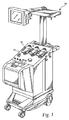
図1は、本開示に従ったカセットとシートと組み合わせて使用され得る、公知の遠心分離流体処理システム10を示す。このシステムは、現在、イリノイ州レイクズーリックのフェンウォール インコーポレイテッドのAMICUS(登録商標)分離器として市販されている。システム10は、種々の流体の処理装置として使用され得るが、特に、全血と他の生物細胞材料の懸濁液の処理によく適合する。システム10は、流体の各成分の密度に基づいて各成分に分離するために適する遠心分離チャンバ(図示しない)を含む。遠心分離器とシステム10の他の要素のより詳細な記述は、ここに参照として組み込まれる米国特許第5,868,696号明細書に見出され得る。本発明の様々な局面が図1のシステム10において使用する文脈において説明されるが、ここで説明されるカセットとシートは、制限ではなく例示として、透析装置のような他の流体処理アプリケーションや他の流体処理システムにおいて使用され得ることを理解されるべきである。 FIG. 1 illustrates a known centrifuge fluid processing system 10 that may be used in combination with cassettes and sheets according to the present disclosure. This system is currently marketed as an AMICUS® separator from Fenwall Incorporated, Lake Zurich, Illinois. The system 10 can be used as a processing device for various fluids, but is particularly well suited for processing suspensions of whole blood and other biological cell materials. The system 10 includes a centrifuge chamber (not shown) suitable for separating the components based on the density of each component of the fluid. A more detailed description of the centrifuge and other elements of the system 10 can be found in US Pat. No. 5,868,696, incorporated herein by reference. While various aspects of the present invention are described in the context of use in the system 10 of FIG. 1, the cassettes and sheets described herein are illustrative and not restrictive for other fluid processing applications such as dialysis machines and others. It should be understood that it can be used in other fluid treatment systems.
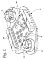
システム10の傾斜したフロントパネルは、少なくとも図2により詳細を示すカセット保持部14を含む。カセット保持部14は、使い捨ての、1回使用の処理セットの処理カセット16(図3および図4)を受容して保持するように構成されている。図1のシステム10を用いた使用に適する処理セットの例は、米国特許第5,868,696号に見出される。しかしながら、ここで記述されるカセットとシートは、本開示の範囲を離れることなく、他の処理セットにも組み込まれ得ると理解されるべきである。
The tilted front panel of the system 10 includes a
図示されたカセット16は、図3,4に示すように、内壁20(図4)によって表側22(図3)と裏側24(図4)とを現すように、または、形成するように仕切られた、射出成形された本体18を含む。説明のために、表側22は、カセット16において、使用中にシステム10とは反対の側を向き、裏側24はシステム10に対向している。柔軟なシート、すなわち、隔膜26は、カセット16の裏側24の上に張り出して、周辺を封止している。後述するように、全体的に硬い上パネル28は、カセット16の表側22の上に張り出して、カセット16内の流路を規定する、盛り上がった壁に封止されている。
As shown in FIGS. 3 and 4, the illustrated
1つの実施形態では、カセット16と、内壁20と、上パネル28は、硬い医療用のプラスチック材料で形成され、シート26は、ポリ塩化ビニルまたはシリコーンのような、柔軟な医療用のプラスチックのシートで形成されている。上パネル28とシート26の周囲は、それぞれ、カセット16の表側22と裏側24の周囲において封止されている。
In one embodiment,
図3と図4に示すように、カセット16の表側22と裏側24は、予め形成された孔を含む。カセット16の裏側24(図4)には、孔が多数のバルブステーション30と多数の圧力感知ステーション32を形成している。カセット16の表側22(図3)では、孔が流体を輸送するための多数の流路または通路34を形成する。バルブステーション30は、予め定められた方法で液路34を相互接続するために、内壁20を通って液体経路34と連通する。感知ステーション32も、選択された領域の圧力を検知するために、内壁20を通って液路34と連通する。液路34、バルブステーション30、感知ステーション32の配置と数は、異なってもよい。図示された実施形態では、カセット16は19の液路34、10のバルブステーション30、4つの感知ステーション32を提供する。
As shown in FIGS. 3 and 4, the front side 22 and the
バルブステーション30と感知ステーション32は、カセットの裏側24(図4)に開口する浅い井戸に似ている。直立する端部36は、内壁20から立ちあがり、バルブステーション30と感知ステーション32の周囲を囲む。バルブステーション30はカセット16の表側22において内壁20によって閉鎖されるが、それぞれのバルブステーション30は内壁20に貫通孔または流体流通ポート38の対を含む。流体流通ポート38は、それぞれ、カセット16の表側22において選択された異なる液路34に通じている。
感知ステーション32は、同様に、カセット16の表側22において内壁20によって閉鎖されるが、それぞれの感知ステーション32は、内壁20に3つの貫通孔またはポート38を含む(図4)。ポート38は、カセット16の表側22において、選択された液路34内に開口している。これらのポート38は、関連付けられた感知ステーション32を通して、液体の流れを、選択された液路34の間に向ける。
The
1つの実施形態においては、カセット16の裏側24に重ねられている柔軟なシート26は、超音波溶接または他の適切な手段によって、バルブステーション30または感知ステーション32の直立する周辺端部36に封止されている。このようにして、バルブステーション30と感知ステーション32は、互いに、また、本システムの他の部分から隔離される。別の実施形態では、柔軟なシート26が、シート26に対してカセット保持部14によって外部から加えられた正の力によって、直立端部36に対して着座し得る。超音波溶接のようなこの正の力は、バルブステーション30と感知ステーション32の周囲を封止する。
In one embodiment, the
バルブステーションに重ねられているシート26の中間領域へのさらなる正の力の局所的な適用(以下、「閉鎖力」という。)は、バルブステーション30内にシート26を曲げるのに役立つ。このような閉鎖力は、カセット保持部14またはそこに関連づけられたバルブ部材によって与えられる。このことはここで詳細に記述される。シート26は、ポート38の1つを封止するようにポート38に合うように配置され、液体の流れに対してバルブステーション30を閉鎖する。閉鎖力が除かれると、バルブステーション30内の流体の圧力および/またはシート26の塑性復元によって、シート26がポート38から離れ、液体の流れに対してバルブステーション30を開放する。最も有利には、シート26は、各バルブステーション30に関連づけられ、シート26がポート38から離れる際にさらに補助するように構成された、偏向部材62(図3,図5)のような偏向する特徴とともに提供される。このことはここで詳細に記述される。
Local application of further positive force (hereinafter referred to as “closing force”) to the intermediate region of the
流路の立ち上がった側面、または、立ち上がった端部40は、内壁20から立ち上がり、液路34を囲み、規定しており、カセット16の表側22では開口している。液路34は、カセット16の裏側24において、バルブステーション30と感知ステーション32(図4)のポート38以外では内壁20によって閉鎖されている。カセット16の表側22に重なっている硬いパネル28は、立ち上がった周囲の端部40に超音波溶接によって封止されて、液路34どうしと、液体34とシステムの他の部分とを封止していることが好ましいが、それ以外を除外しない。
The rising side surface or the rising
図示された実施形態では、複数の(例えば10の)予成形された管接続具42がカセット16の対辺の端部44,46から延び出ている。管接続具42は、5つが一方の側の端部44上に配列され、5つが他の側の端部46に配列されている。カセット16の他の側端部48には、図示されているように、管接続具が配置されていない。管接続具42は、使い捨てセットの残りの部分とともにカセット16に接続される外部の管(図示されていない)に接続される。
In the illustrated embodiment, a plurality (eg, ten) of pre-formed pipe fittings 42 extend from opposite ends 44, 46 of the
管接続具42は、流体が通ってカセット16に出入りするカセット16の液路を構成しており、種々の内部液路34に連通している。カセット16の他の内部液路34は、バルブステーション30と感知ステーション32を通って管接続具42に関連づけられる液路34を互いに接続する分岐液路を構成している。
The pipe connector 42 constitutes a liquid path of the
次に、カセット保持部14(図2)は、2つの対辺の側端部48に沿って所望の操作位置においてカセット16を受容し、保持または把持する。カセット保持部14は、一対の蠕動ポンプステーション50を含む。カセット16がカセット保持部14に把持されると、カセット16から延びている管のループ(選択された管接続具42によって規定される)は、ポンプステーション50と動作可能に係合される。ポンプステーション50は流体がカセット16を通って流れるように動かされる。
Next, the cassette holder 14 (FIG. 2) receives and holds or grips the
カセット16の裏側24を覆う柔軟なシート26は、弁と感知部の配列または集合54に密着するように、カセット保持部14によって圧迫される(図6、図7)。弁の集合54は、カセット16のバルブステーション30と感知ステーション32と協働する。特に図2に図示される弁の集合54は、10のバルブアクチュエータ56と4つの圧力感知変換器58とを含むが、これらのアクチュエータと変換器の数は規制されない。バルブアクチュエータ56と圧力感知変換器58は、カセット16の裏側24上に、バルブステーション32と感知ステーション32と同じ配置で、相互に配置される。カセット16がカセット保持部14に取り付けられると、バルブアクチュエータ56は、バルブステーション30と揃うように配置される。同時に、圧力感知変換器58は、カセット感知ステーション32と互いに揃うように配置される。
The
圧力感知変換器58は、カセット16の感知ステーション32内の液圧を感知する。感知された圧力は、全体システム監視機能の一部として、システム10の制御部に送られる。
The
バルブアクチュエータ56に関しては、それぞれが、電気的に作動するソレノイド・ピンまたはピストン60を含む。それぞれのピストン60は、引込位置(図6)と伸長位置(図7)との間で独立して可動である。伸長位置にあるとき、ピストン60はシート26において関連付けられているバルブステーション30に重なっている領域を押す。この位置では、ピストン60は、シート26を、関連付けられているバルブステーション30の中に曲げ、これによって、関連づけられているバルブポート38を封止する。これは、液体の流れに対してバルブステーション30を閉鎖する。引込位置では、ピストン60はシート26に力を加えない。上述のように、シート26の塑性復元力と偏向部材62が、シート26がバルブポート38から離れるようにシート26をカセット本体18から偏向させ、それによって、バルブステーション30が液体の流れに対して開放される。
With respect to the
図5は、偏向部材62の特定の実施形態を示す。本開示に従った偏向部材の他の実施形態については、図8(偏向部材62aとして示されている)と、図9(偏向部材62bとして示されている)に図示されている。種々の偏向部材の実施形態は、1つの偏向部材しか有しない特有のシート26とともに(図3を参照)、別々に示されている。これは、種々の偏向部材から単一の応答を得るという観点で、有利であり得るが、特定のシート26が異なる構造の偏向部材を含むということも、関連付けられるバルブステーション30の要求が変化した場合には有利であり得、これもまた本願の開示の範囲内にある。
FIG. 5 shows a specific embodiment of the
シート26は、カセット本体18に対向する側に関連づけられたそれぞれの偏向部材62〜62bを有する全体的に柔軟な層64(すなわち、隔膜状の柔軟なシートで、カセット16の裏側24に重ねられている)から構成されている。特に、それぞれの偏向部材62〜62bは、図6〜9に示すように、バルブステーション30の1つに受容されて、内壁20とシート26の全体的に柔軟な層64との間に位置するように構成されている。バルブステーション30内の偏向部材62〜62bの特定の位置は、後に詳述するように、変化し得る。
The
図5の実施形態においては、偏向部材62は、ピストン60(図6,図7を参照)の動きによって閉鎖されるポート38aに隣接するように向きが合わせられており、ここでは第1のポートと称する場合がある。偏向部材62は、完全な円形ではなく、すなわち、完全にポート38aを囲んでおらず、図5(ポート38aとポート38bの相対的な位置を破線で示す。)に最もよく示されているように、部分的にのみ、または、ほとんどポート38aを囲んでいる。図5の偏向部材62は、(図5に図示されているように)偏向部材66の最大高さよりも低い、または、高さがゼロの(すなわち、単に全体的に柔軟な層64のみが開口66の位置にある)開口または通路66を含む。
In the embodiment of FIG. 5, the
一つの実施形態においては、偏向部材62は、ピストン60が伸長位置(図7)にあるか引込位置(図6)にあるかに関わらず、内壁20に常に接触するように構成されている。開口66を設けることによって、偏向部材62が内壁20に接触していても、ピストンが引込位置(図6)にある時、流体はポート38aとポート38bの間を通ることができる。図5の実施形態においては、開口66は、ポート38aとポート38bとの間に直接的な、または、直線的な流路を与えるように方向づけられているが、開口66は、本願の開示を逸脱しない範囲で、他の位置(すなわち、異なる角度の位置)に置かれてもよい。しかしながら、開口66がポート38aとポート38bとの間で直接的な流体流通路を与えることは、ポート38aとポート38bとの間の流路長さを短くするために有利であり得る。
In one embodiment, the
図示された実施形態においては、偏向部材62は、全体的にポート38aと協働し、開口66を規定するように、全体的に弓型またはCの字型である。偏向部材62は、180°よりも大きい、または300°よりも大きく、ほとんど、しかし完全にではなく、ポート38aを囲み、開口66を規定し得る。図示された構成は、単に例示であり、開口66を規定するために、偏向部材は必ずしも円形や半円形である必要はなく、他のいかなる(必然ではないが好ましくは、閉じられていない)形状をも有し得る。例えば、全体的に正方形、卵型、多角形、または他の形状であり得る。偏向部材62がピストン60の先端または最上端から離間されるように(すなわち、一直線上に揃わないように)構成され配置されることは、有利であり得る。例えば、図5〜図7の実施形態においては、偏向部材62は、全体的にピストン60の最上端または先端の周囲と同じ大きさ(またはわずかに大きい)開けた内部を規定し、ピストン60は、図7に示す伸長位置において、偏向部材60を直接圧縮しない。さらに、図5〜図7は、開口66とその隣接部分を除いて全体的に単一の高さを有する偏向部材62を示すが、偏向部材62が開口66以外の位置においても非単一の高さを有することも本開示の範囲内である。
In the illustrated embodiment, the
図5の偏向部材62は、全体的に柔軟な層64と同じ材質(一実施形態としてシリコーンであり得る)または異なる材質で構成され得る。偏向部材62と全体的に柔軟な層64が同一の材質で構成されている場合、偏向部材62は全体的に柔軟な層64と同時に形成されて、全体的に柔軟な層64に成形された突起または延出部として構成され得る。あるいは、偏向部材62は、全体的に柔軟な層64と同一の材質で構成されているか異なる材質で構成されているかに関わらず、全体的に柔軟な層64に別個に(例えば、接着剤または溶接または他の適切な固定方法によって)固定され得る。
The
他の実施形態においては、偏向部材62は、全体的に柔軟な層64に固定されるよりもむしろ、カセット本体18の内壁20(またはカセット本体18の他の部分)に固定され得る。偏向部材62がシート26の全体的に柔軟な層64とカセット本体18の両方に固定されることも、いずれにも固定されない(例えば、偏向部材62を全体的に柔軟な層64と内壁20との間の空間内に圧入することによって固定する)こともまた本開示の範囲内である。
In other embodiments, the deflecting
使用においては、カセット16は、弁の集合54上に、シート26の全体的に柔軟な層64とともに、バルブアクチュエータ56と、バルブアクチュエータ56と整列されたバルブステーション30とに係合されるように(任意で、バルブアクチュエータ56の上に位置する弁の集合54の膜またはカバーとともに)、載せられる。カセット16が弁の集合54に載せられるとき、バルブアクチュエータ56のピストンは図6の引込位置にある。ピストン60が引込位置にあると、流体はポート38aとポート38bとの間で流れることができる。一つの実施形態においては、流体は、図6に示すように、ポート38aから、偏向部材62によって規定される開口66を通って、ポート38bに流れ込み、カセット16を連続して流れる。他の実施形態においては、流体は、第2のポート38bから第1のポート38aに、偏向部材62の開口66を経由して、逆向きに流れ得る。
In use, the
流体にバルブステーション30を通過させないことが望ましくなれば、ピストン60は、引込位置から図7に示す伸長位置に移るように作動する。伸長位置では、ピストン60は、シート26の全体的に柔軟な層64をカセット16の内壁20に向かって押圧し、ポート38aが覆われ、流体にバルブステーション30を通過させない。偏向部材62は、内壁20へのシート26の動きに抵抗するが、ピストン60が内壁20に対して全体的に柔軟な層64を完全に設置するためには十分に従順である。ピストン60で直接、押圧することは必ずしも必要でないが、偏向部材62は、ピストン60が伸長位置にある時、図7に示すように、変形されて押圧される。
If it is desirable not to allow fluid to pass through the
バルブステーション30を通過するように流体を流すことが再び望ましくなった場合には、ピストン60は、図7に示した伸長位置から図6に示す引込位置に移るために作動する。カセット16内における流体の流れによって生成された真空によって、シート26は当初の、付勢されていない図6に示す形状に戻ろうとするが、これは、全体的に柔軟な層64をポート38aから完全に離すには十分でない場合がある。全体的に柔軟な層64と比較して、偏向部材64は、当初の図6の形状に戻る、より大きな弾力性または能力がある。従って、シート26からピストン60の力を除くことで、偏向部材62は当初の形状に戻り、その時に、全体的に柔軟な層64がポート38aから離れて、シート26も当初の形状に戻される。
When it is again desirable to flow fluid through the
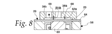
別の実施形態においては、図5に示す実施形態と同様、図8に示すように、偏向部材62aはピストン60の動きによって閉鎖されるポート38aに隣接するように位置決めされている。しかしながら、図8の偏向部材62aは、単にポート38aの周囲の一部を囲むだけでなく、完全な円形または完全に38aを囲んでもよい。偏向部材62aが常に(ピストン60が図6の引込位置にある時を含む)カセットの内壁20に接触するように構成されているとしても、流体は偏向部材62aを通って、ポート38aと38bの間を流れ得る。これは、多数の方向のいずれにおいても達成され得る。図8に図示された実施形態では、偏向部材62aは、波形ばねまたはコイルばねのようなばねを備える。流体が流れるように、隣接するばねとばねの間には開けた空間がある。偏向部材62aは、波形ばねまたはコイルばねとして与えられるのであれば、金属材料や高分子材料を含む多数の材料のいずれによっても構成され得る。他の実施形態においては、偏向部材は、流体が偏向部材を通って流れるように、発泡インサートやリングのような、全体的に開いた形状または多孔質構造を有し得る。偏向部材の他の構造としては、偏向部材を通って流体を流すことができるものは、本開示の範囲から逸脱しないものであれば使用され得る。
In another embodiment, similar to the embodiment shown in FIG. 5, as shown in FIG. 8, the deflecting
図示された実施形態において、ピストン60が伸長位置にある時に偏向部材62aを直接、押圧しないように、偏向部材62aの内径はピストン60の最上端部の周辺部よりもわずかに大きく、一般的にポート38aと同心である。しかしながら、偏向部材62aがポート38aと同心でないこと、および/または、ピストン60の最上端部の周辺部以下の内径を有することも、本開示の範囲内である。さらに、本開示の範囲を逸脱しない範囲で、偏向部材62aは、実質的に環状であってもよいし、非環状であってもよい。
In the illustrated embodiment, the inner diameter of the deflecting
図8は、偏向部材62aの一端を受容するための溝または流路または凹部68を含むように変形されたカセット16の内壁20を示す。凹部68は、その中の偏向部材62aを固定するための、接着性または他の手段を含み得る。他の実施形態においては、偏向部材62の一端は、内壁20に固定されるように、凹部68に圧入される。他の実施形態においては、偏向部材は、偏向部材62aが関連づけられたポート38aに対して適当な状態に保たれるように、凹部68にゆるく適合するように構成され得る。偏向部材62aの反対側は、シート26の全体的に柔軟な層64に固定されていてもよく、分離されていてもよい。凹部68を省略し、偏向部材62aを直接、カセットの内壁20やシート26の全体的に柔軟な層64に固定することも、本開示の範囲内である。
FIG. 8 shows the
使用時には、図8の偏向部材62aは、図5〜図7の偏向部材62と同様に動作する。カセット16が弁集合54上に載せられると、バルブアクチュエータ56のピストン60が図8の引込位置にあり、流体が偏向部材62aを通ってポート38aと38bとの間を流れるようにされる。バルブステーション30を流体に通過させないことが望まれる時には、ピストン60が引込位置から伸長位置に移るように作動し、ピストン60は、シート26の全体的に柔軟な層64をカセット16の内壁20に向かって押圧し、ポート38aを覆わせることによって、バルブステーションを通って流体が流れることを防ぐ。偏向部材62は、内壁20へのシート26の動きに抵抗するが、ピストン60が内壁20に対して全体的に柔軟な層64を完全に設置するためには十分に従順である。ピストン60で直接、押圧することは必ずしも必要でないが、偏向部材62は、ピストン60が伸長位置にある時、変形されて押圧される。
In use, the
バルブステーション30を通過するように流体を流すことが再び望ましくなった場合には、ピストン60は、図8に示した引込位置に戻るように作動する。偏向部材62aが押圧された状態(ピストン60が伸長しているとき)から緩和された、または当初の状態(図8)に戻ろうする傾向は、全体的に柔軟な層64をポート38aから離してシート26を当初の形状に戻すのに役立つ。
When it is again desirable to flow fluid through the
別の実施形態においては、図5と図8に示す実施形態と同様、図9に示すように、偏向部材62bはピストン60の動作によって閉鎖されるポート38aに隣接するように位置決めされている。しかしながら、図9の偏向部材62bは、ポート38aの一部を囲むよりもむしろ、ポート38bとは独立して構成されている(すなわち、ポート38aを囲んだり、ポート38aに沿う形状には形成されていない)。ポート38aから独立するように、偏向部材62,62aが移動され、および/または、形状が変更され得ることは言うまでもない。また、そのような偏向部材62,62aの形状と位置は、関連付けられたポート38aに依存した形状および/または位置に限定されない。
In another embodiment, similar to the embodiment shown in FIGS. 5 and 8, as shown in FIG. 9, the
図示された実施形態においては、偏向部材62bは、第2のポート38bの反対側(すなわち、第1のポート38aから見て、第2のポート38aから180°離れた位置)に位置する。この位置は、偏向部材62aがポート38a,38bの間で流れに干渉することを防ぐのに役立つ。しかしながら、偏向部材62bが、(構成によって)偏向部材62bを通って、および/または、偏向部材の周囲で流体の連通をさせるように、2つのポート38a,38bの間を含む他の位置に配置されることは本開示の範囲内である。最も有利には、偏向部材62bは、ピストン60の機能を損なうことなく強いばねの応答を与える、ピストン60の最上端の周囲に隣接して配置される。しかしながら、偏向部材62bが、ピストン60とポート38aからさらに遠い位置を含む、バルブステーション30内の他の位置に配置されることもまた本開示の範囲内である。
In the illustrated embodiment, the deflecting
図9に示す偏向部材62bは、多数の材質のいずれによっても構成され得る。例えば、(図5に示す実施形態のように)全体的に柔軟な層64と同じ材質で構成され得る。また、(図8に示す実施形態のように)金属または高分子または発泡材料によって構成され得る。図示された実施形態では、偏向部材62bは、弾性を有するスペーサーまたはインサートを備える。さらに、バルブステーション30内には、1つ以上の偏向部材62bが配置され、特定のバルブステーション30内の種々の偏向部材は異なる形状にされ得る。例えば、特定のバルブステーション30には弾性材料のスペーサーまたはインサートによって構成される1つの偏向部材と金属の板ばねによって構成される別の偏向部材が与えられ得る。偏向部材62bは、全体的に柔軟な層64および/または内壁20に、適切な手段によって固定され得る。また、そのいずれの表面にも固定されない場合もあり得る。
The
図9の偏向部材62bは、図5〜図8の偏向部材62,62aと同様に動作し、ピストン60が伸長位置に移動すれば押圧され、その後、ピストン60が引込位置に戻ると、当初の形状に戻り、全体的に柔軟な層64がポート38aから離れることと、シート26が当初の形状に戻ることを補助する。
The
ここに図示された偏向部材に加えて、他の構成も、本開示の範囲を逸脱することなく、使用され得る。例えば、偏向部材は完全にまたは部分的にポート38aと38bの両方を囲むか、第2のポート38b(すなわち、ピストン60によって直接弁の開閉をされないポート)のみを囲むように構成され得る。また、偏向部材は、必ずしも常にカセットの内壁20に接触する必要はなく、ピストン60が引込位置にある時には離れて、ピストン60が伸長位置にあるかまたは伸長位置と引込位置の中間の位置にある時のみ内壁20に接触してもよい。
In addition to the deflecting members illustrated herein, other configurations may be used without departing from the scope of this disclosure. For example, the deflection member may be configured to completely or partially surround both
さらに、ここで図示され説明された偏向部材は比較的弾力があるが(すなわち、ピストン60によって力を加えられると変形し、その後、当初の形状に戻る傾向がある)、弾性のない構成も使用され得る。例えば、偏向部材は、硬い、実質的に変形しない、好ましくは第1のポート38aに隣接して位置してシート26の方に延びる、カセット本体18から突出する突起によって構成され得る。このような突起は、カセット本体18と一体的に形成され得るか、別個に形成されてカセット本体18に実質的に固定される。他には、突起はカセット本体18ではなく、シート26に固定され得る。突起は、シート26がカセット本体18の方に向かう動きに抵抗して、シート26がポート38aを覆った状態で押されるように構成される。このように、本質的に弾性体よりもむしろ実質的に硬い突起が存在するだけで、シート26を閉鎖位置から開放位置に偏向させるのに役立つ。
In addition, the deflecting member shown and described herein is relatively resilient (ie, tends to deform when applied by the
上述の本主題は、単独でも、または、1以上を他の局面と組み合わせてもよい。前述の説明を制限することなく、主題の1つの局面に従って、流体処理カセットに用いられる、複数の流体ポートがある少なくとも1つのバルブステーションを有するシートが提供される。シートは全体的に柔軟な層と偏向部材を備える。シートは、第1と第2の面を有し、カセットのバルブステーションに受容されるように構成された、全体的に柔軟な層の1つの面に関連づけられる偏向部材を有する。 The subject matter described above may be used alone or in combination with one or more other aspects. Without limiting the foregoing description, in accordance with one aspect of the subject matter, a seat having at least one valve station with a plurality of fluid ports for use in a fluid treatment cassette is provided. The sheet generally comprises a flexible layer and a deflecting member. The sheet has first and second surfaces and a deflecting member associated with one surface of the generally flexible layer configured to be received by the valve station of the cassette.
前述の局面とともに使用されまたは組み合わされ得る他の開示に従えば、偏向部材は、全体的に柔軟な層と同じ材質で構成されている。 In accordance with other disclosures that may be used or combined with the foregoing aspects, the deflecting member is generally composed of the same material as the flexible layer.
前述のいずれかの局面とともに使用されまたは組み合わされ得る他の開示に従えば、偏向部材は、全体的に柔軟な層の成形された突起を有する。 In accordance with other disclosures that may be used or combined with any of the foregoing aspects, the deflecting member has a generally flexible layer of shaped projections.
前述のいずれかの局面とともに使用されまたは組み合わされ得る他の開示に従えば、偏向部材は、全体的に弓型である。 In accordance with other disclosures that can be used or combined with any of the foregoing aspects, the deflection member is generally arcuate.
前述のいずれかの局面とともに使用されまたは組み合わされ得る他の開示に従えば、偏向部材は全体的にC型である。 In accordance with other disclosures that may be used or combined with any of the foregoing aspects, the deflecting member is generally C-shaped.
第1の局面とともに使用されまたは組み合わされ得る他の開示に従えば、偏向部材はバネを備える。 According to another disclosure that may be used or combined with the first aspect, the deflecting member comprises a spring.
第1の局面とともに使用されまたは組み合わされ得る他の開示に従えば、偏向部材は発泡インサートを備える。 In accordance with other disclosures that may be used or combined with the first aspect, the deflection member comprises a foam insert.
別の局面に従えば、表側と裏側を規定する内壁を含む流体処理カセットが提供される。少なくとも1つのバルブステーションは、内壁の裏側に関連付けられている。複数の流体流通ポートはバルブステーションの1つに関連づけられている。カセットはまた、第1と第2の面を有する、全体的に柔軟な層を備えるシートを含む。偏向部材は、全体的に柔軟な層の1つの面に関連づけられて、バルブステーション内において、内壁と全体的に柔軟な層との間に配置されている。 According to another aspect, a fluid treatment cassette is provided that includes an inner wall defining a front side and a back side. At least one valve station is associated with the back side of the inner wall. A plurality of fluid flow ports are associated with one of the valve stations. The cassette also includes a sheet with a generally flexible layer having first and second sides. The deflection member is associated with one face of the generally flexible layer and is disposed in the valve station between the inner wall and the generally flexible layer.
直前の局面とともに使用されまたは組み合わされ得る他の開示に従えば、偏向部材は、全体的に柔軟な層と同じ材質で構成されている。 In accordance with other disclosures that may be used or combined with the previous aspects, the deflection member is generally composed of the same material as the flexible layer.
前述の2つのいずれかの局面とともに使用されまたは組み合わされ得る他の開示に従えば、偏向部材は、全体的に柔軟な層の成形された突起を有する。 In accordance with other disclosures that may be used or combined with either of the two aforementioned aspects, the deflection member has a generally flexible layer of shaped projections.
前述の3つのいずれかの局面とともに使用されまたは組み合わされ得る他の開示に従えば、偏向部材は、全体的に弓型である。 In accordance with other disclosures that may be used or combined with any of the three aspects described above, the deflecting member is generally arcuate.
前述の4つのいずれかの局面とともに使用されまたは組み合わされ得る他の開示に従えば、偏向部材は全体的にC型である。 In accordance with other disclosures that may be used or combined with any of the four aspects described above, the deflection member is generally C-shaped.
第8の局面とともに使用されまたは組み合わされ得る他の開示に従えば、偏向部材はバネを備える。 According to other disclosures that may be used or combined with the eighth aspect, the deflection member comprises a spring.
第8の局面とともに使用されまたは組み合わされ得る他の開示に従えば、偏向部材は発泡インサートを備える。 According to other disclosures that may be used or combined with the eighth aspect, the deflecting member comprises a foam insert.
前述の7つのいずれかの局面とともに使用されまたは組み合わされ得る他の開示に従えば、偏向部材は、内壁と全体的に柔軟な層とに係合している。 In accordance with other disclosures that may be used or combined with any of the seven aspects described above, the deflection member engages the inner wall and the generally flexible layer.
前述の8つのいずれかの局面とともに使用されまたは組み合わされ得る他の開示に従えば、内壁は、偏向部材の1つを受容する流路を含む。 In accordance with other disclosures that may be used or combined with any of the eight aspects described above, the inner wall includes a flow path that receives one of the deflection members.
前述の9つのいずれかの局面とともに使用されまたは組み合わされ得る他の開示に従えば、偏向部材は、流体流通ポートの1つを部分的に囲んでいる、 According to other disclosures that may be used or combined with any of the nine aspects described above, the deflection member partially surrounds one of the fluid flow ports.
第8の局面とともに使用されまたは組み合わされ得る他の開示に従えば、偏向部材は流体流通ポートの1つを囲む。 According to other disclosures that may be used or combined with the eighth aspect, the deflection member surrounds one of the fluid flow ports.
別の局面に従えば、流体処理システムと使い捨て処理セットとの組合せが提供される。この組み合わせは、流体処理カセットとバルブアクチュエータとを含む。流体処理カセットは、内壁と、少なくとも1つのバルブステーションと、複数の流体流通ポートと、シートとを含む。内壁は、表側と裏側とを規定し、少なくとも1つのバルブステーションは、内壁の裏側に関連づけられる。複数の流体流通ポートは、1つのバルブステーションに関連づけられる。シートは、第1と第2の面を有する全体的に柔軟な層と、1つの面に関連づけられる偏向部材とを含む。偏向部材は、バルブステーション内において、内壁と全体的に柔軟な層との間に配置される。 According to another aspect, a combination of a fluid treatment system and a disposable treatment set is provided. This combination includes a fluid treatment cassette and a valve actuator. The fluid treatment cassette includes an inner wall, at least one valve station, a plurality of fluid flow ports, and a seat. The inner wall defines a front side and a back side, and at least one valve station is associated with the back side of the inner wall. Multiple fluid flow ports are associated with one valve station. The sheet includes a generally flexible layer having first and second surfaces and a deflection member associated with one surface. The deflection member is disposed in the valve station between the inner wall and the generally flexible layer.
直前の局面とともに使用されまたは組み合わされ得る他の開示に従えば、偏向部材は、全体的に柔軟な層と同じ材質で構成されている。 In accordance with other disclosures that may be used or combined with the previous aspects, the deflection member is generally composed of the same material as the flexible layer.
前述の2つのいずれかの局面とともに使用されまたは組み合わされ得る他の開示に従えば、偏向部材は、全体的に柔軟な層の成形された突起を備える。 In accordance with other disclosures that may be used or combined with either of the two aforementioned aspects, the deflection member comprises a generally flexible layer of shaped projections.
前述の3つのいずれかの局面とともに使用されまたは組み合わされ得る他の開示に従えば、偏向部材は全体的に弓型である。 In accordance with other disclosures that may be used or combined with any of the three aspects described above, the deflection member is generally arcuate.
前述の4つのいずれかの局面とともに使用されまたは組み合わされ得る他の開示に従えば、偏向部材は全体的にC型である。 In accordance with other disclosures that may be used or combined with any of the four aspects described above, the deflection member is generally C-shaped.
第19の局面とともに使用されまたは組み合わされ得る他の開示に従えば、偏向部材はばねを備える。 According to another disclosure that may be used or combined with the nineteenth aspect, the deflecting member comprises a spring.
第19の局面とともに使用されまたは組み合わされ得る他の開示に従えば、偏向部材は発泡インサートを備える。 According to other disclosures that may be used or combined with the nineteenth aspect, the deflecting member comprises a foam insert.
前述の7つのいずれかの局面とともに使用されまたは組み合わされ得る他の開示に従えば、偏向部材は、ピストンが伸長位置と引込位置にある時、内壁と全体的に柔軟な層に係合する。 In accordance with other disclosures that can be used or combined with any of the seven aspects described above, the deflecting member engages the inner wall and the generally flexible layer when the piston is in the extended and retracted positions.
前述の8つのいずれかの局面とともに使用されまたは組み合わされ得る他の開示に従えば、内壁は、偏向部材の一端を受容する流路を含む。 In accordance with other disclosures that may be used or combined with any of the eight aspects described above, the inner wall includes a flow path that receives one end of the deflection member.
前述の9つのいずれかの局面とともに使用されまたは組み合わされ得る他の開示に従えば、偏向部材は部分的に流体流通ポートの1つを囲む。 In accordance with other disclosures that may be used or combined with any of the nine aspects described above, the deflecting member partially surrounds one of the fluid flow ports.
第19の局面とともに使用されまたは組み合わされ得る他の開示に従えば、偏向部材は1つの流体流路ポートを囲んでいる。 According to other disclosures that may be used or combined with the nineteenth aspect, the deflection member surrounds one fluid flow path port.
上に図示され説明された実施形態は、本主題の原則のいくつかの応用であると理解されるべきである。当業者によって、別個に開示またはここに特許請求された特徴の組み合わせを含む、特許請求された主題の精神と範囲とから逸脱することなしに、多くの変形がされ得る。これらの理由によって、範囲は上述の説明に限定されず、特許請求の範囲に従い、特許請求の範囲がシート単独、シートと装置またはカセットとの組合せ、および/または、シートと装置とカセットとの組合せに向けられていると理解される。 The embodiments illustrated and described above are to be understood as being some application of the principles of the present subject matter. Many variations may be made by those skilled in the art without departing from the spirit and scope of the claimed subject matter, including combinations of features separately disclosed or claimed herein. For these reasons, the scope is not limited to the above description, and according to the claims, the claims are based on sheets alone, a combination of sheets and apparatus or cassette, and / or a combination of sheets, apparatus and cassette Is understood to be directed to
Claims (29)
前記内壁の裏側に関連づけられる少なくとも1つのバルブステーションと、
前記バルブステーションの少なくとも1つに関連づけられる複数の流体流通ポートと、
シートとを備え、
前記シートは、第1の面と第2の面とを有する全体的に柔軟な層と、少なくとも1つの前記バルブステーション内で、前記全体的に柔軟な層の1つの面に関連づけられて前記内壁と前記全体的に柔軟な層との間に位置し、前記シートを前記複数の流体流通ポートの1つから離すように偏向させる偏向部材とを含む、流体処理カセット。 An inner wall defining a front side and a back side;
At least one valve station associated with the back side of the inner wall;
A plurality of fluid flow ports associated with at least one of the valve stations;
With seats,
The seat has a generally flexible layer having a first surface and a second surface, and the inner wall is associated with one surface of the generally flexible layer in at least one of the valve stations. said located between the overall flexible layer, and a deflection member which Ru is deflected so as to release the said sheet from one of said plurality of fluid flow ports, the fluid treatment cassette.
流体処理カセットと、バルブアクチュエータとを備え、
前記流体処理カセットは、
表側と裏側とを規定する内壁と、
前記内壁の裏側に関連づけられた少なくとも1つのバルブステーションと、
少なくとも1つの前記バルブステーションに関連づけられた複数の流体流通ポートと、
シートとを備え、
前記シートは、
第1と第2の面を有する全体的に柔軟な層を備え、
少なくとも1つの前記バルブステーション内において、前記全体的に柔軟な層の1つの面に関連づけられて前記内壁と前記全体的に柔軟な層との間に配置される偏向部材とを備え、
前記バルブアクチュエータは、前記カセットの前記シートに係合するように構成されて、前記カセットの前記シートに係合する時、複数の前記流体流通ポートの1つと実質的に直線上に整列されるピストンを含み、
前記ピストンは、前記ピストンが前記シートを前記カセットの前記内壁に向かって押圧して複数の前記流体流通ポートの1つを覆うことによって流体が少なくとも1つの前記バルブステーションを通って流れないようにする伸長位置と、前記ピストンがカセットがから離れて前記シートが複数の前記流体流通ポートの1つを覆わないようにすることによって流体が少なくとも1つの前記バルブステーションを通って流れるようにする引込位置との間で動くように構成され、
前記偏向部材は、前記ピストンが前記伸長位置から前記引込位置に動く時に前記シートを複数の前記流体流通ポートの1つから離すことを補助するように構成されている、流体処理システムと使い捨て処理セットの組み合わせ。 A combination of a fluid treatment system and a disposable treatment set,
A fluid treatment cassette and a valve actuator;
The fluid treatment cassette is
An inner wall defining a front side and a back side;
At least one valve station associated with the back side of the inner wall;
A plurality of fluid flow ports associated with at least one said valve station;
With seats,
The sheet is
Comprising a generally flexible layer having first and second faces;
A deflecting member disposed between the inner wall and the generally flexible layer in relation to one face of the generally flexible layer within at least one of the valve stations;
The valve actuator may be configured to engage the seat of the cassette, when engaging the sheet of the cassette is aligned in a substantially straight line and one of a plurality of said fluid flow ports piston only contains that,
The piston prevents fluid from flowing through at least one of the valve stations by pressing the seat against the inner wall of the cassette to cover one of the plurality of fluid flow ports. and extended position, a retracted position fluid you to flow through at least one of said valve station by not cover one of the sheet a plurality of said fluid flow port away the piston from the cassette Configured to move between and
The deflection member, the piston is configured to assist in releasing from the sheet one of the plurality of fluid flow ports when moving to the retracted position from the extended position, the fluid treatment system and a disposable processing set Combination.
第1と第2の面を有する全体的に柔軟な層と、
前記全体的に柔軟な層の1つの面に関連づけられてカセットのバルブステーション内に受容されるように構成され、前記シートを前記複数の流体流通ポートの1つから離すように偏向させる偏向部材とを備える、シート。 A sheet for use in a fluid treatment cassette having at least one valve station with a plurality of fluid flow ports,
A generally flexible layer having first and second faces;
A deflecting member configured to be received within a valve station of a cassette associated with one face of the generally flexible layer and deflecting the seat away from one of the plurality of fluid flow ports ; Comprising a sheet.
Applications Claiming Priority (3)
| Application Number | Priority Date | Filing Date | Title |
|---|---|---|---|
| US201261693804P | 2012-08-28 | 2012-08-28 | |
| US61/693,804 | 2012-08-28 | ||
| PCT/US2013/030130 WO2014035471A1 (en) | 2012-08-28 | 2013-03-11 | Spring-open sheeting for fluid processing cassette |
Publications (2)
| Publication Number | Publication Date |
|---|---|
| JP2015526240A JP2015526240A (en) | 2015-09-10 |
| JP6138940B2 true JP6138940B2 (en) | 2017-05-31 |
Family
ID=48143348
Family Applications (1)
| Application Number | Title | Priority Date | Filing Date |
|---|---|---|---|
| JP2015529784A Active JP6138940B2 (en) | 2012-08-28 | 2013-03-11 | Spring-loaded sheet for fluid treatment cassette |
Country Status (7)
| Country | Link |
|---|---|
| US (1) | US10010886B2 (en) |
| EP (1) | EP2890421B1 (en) |
| JP (1) | JP6138940B2 (en) |
| CN (1) | CN104602724B (en) |
| AU (1) | AU2013309502B2 (en) |
| IN (1) | IN2015DN00987A (en) |
| WO (1) | WO2014035471A1 (en) |
Families Citing this family (7)
| Publication number | Priority date | Publication date | Assignee | Title |
|---|---|---|---|---|
| DE102014103491A1 (en) * | 2014-03-14 | 2015-09-17 | Fresenius Medical Care Deutschland Gmbh | Blood treatment cassette with foil valve and inelastic spacer as well as blood treatment device |
| DE102014103492A1 (en) | 2014-03-14 | 2015-09-17 | Fresenius Medical Care Deutschland Gmbh | Fluid cartridge with tilt-tolerant centering latch and blood treatment device |
| DE102014103490A1 (en) * | 2014-03-14 | 2015-09-17 | Fresenius Medical Care Deutschland Gmbh | Blood treatment cassette with foil valve and elastic spacer as well as blood treatment device |
| EP3207949B1 (en) * | 2016-02-19 | 2018-11-28 | Fenwal, Inc. | System for improved fluid flow control within a fluid circuit cassette |
| EP3641850A4 (en) * | 2017-06-24 | 2021-03-17 | NxStage Medical Inc. | Peritoneal dialysis fluid preparation and/or treatment devices methods and systems |
| WO2019169081A2 (en) | 2018-02-28 | 2019-09-06 | Nxstage Medical, Inc. | Fluid preparation and treatment devices, methods, and systems |
| IT202000030338A1 (en) | 2020-12-10 | 2022-06-10 | Baxter Int | MEDICAL APPARATUS |
Family Cites Families (23)
| Publication number | Priority date | Publication date | Assignee | Title |
|---|---|---|---|---|
| US5381510A (en) * | 1991-03-15 | 1995-01-10 | In-Touch Products Co. | In-line fluid heating apparatus with gradation of heat energy from inlet to outlet |
| DE4336336A1 (en) | 1992-11-23 | 1994-05-26 | Lang Volker | Cassette infusion system |
| US5462416A (en) | 1993-12-22 | 1995-10-31 | Baxter International Inc. | Peristaltic pump tube cassette for blood processing systems |
| US5746708A (en) | 1993-12-22 | 1998-05-05 | Baxter International Inc. | Peristaltic pump tube holder with pump tube shield and cover |
| US5812168A (en) * | 1994-10-31 | 1998-09-22 | Hewlett-Packard Company | Air purging of a pressure regulated free-ink ink-jet pen |
| US5837905A (en) | 1996-07-24 | 1998-11-17 | Gish Biomedical, Inc. | Cardioplegia monitoring system, flow cell cassette, variable ratio valve, and method |
| EP1504777A1 (en) * | 1996-11-22 | 2005-02-09 | Therakos, Inc. | Integrated cassette for valving pumping and controlling movement of fluids |
| DE69938202T3 (en) * | 1998-07-15 | 2013-06-13 | Seiko Epson Corp. | An ink supply system |
| US6620189B1 (en) * | 2000-02-28 | 2003-09-16 | Radiant Medical, Inc. | Method and system for control of a patient's body temperature by way of a transluminally insertable heat exchange catheter |
| AU776741B2 (en) * | 1999-09-03 | 2004-09-23 | Fenwal, Inc. | Programmable, fluid pressure actuated blood processing systems and methods |
| CN1280103C (en) * | 2000-02-16 | 2006-10-18 | 精工爱普生株式会社 | Cartriage and connecting assembly for ink-jet printer and ink-jet printer |
| ATE398023T1 (en) * | 2000-10-20 | 2008-07-15 | Seiko Epson Corp | INK CARTRIDGE FOR INKJET RECORDING DEVICE |
| US6494694B2 (en) * | 2001-04-25 | 2002-12-17 | Abbott Laboratories | Disposable infusion cassette with low air bubble retention and improved valves |
| DE10224750A1 (en) | 2002-06-04 | 2003-12-24 | Fresenius Medical Care De Gmbh | Device for the treatment of a medical fluid |
| US7238164B2 (en) * | 2002-07-19 | 2007-07-03 | Baxter International Inc. | Systems, methods and apparatuses for pumping cassette-based therapies |
| ES2426941T3 (en) * | 2005-02-07 | 2013-10-25 | Hanuman Llc | Apparatus and procedure of platelet rich plasma concentrates |
| CA2702385C (en) * | 2007-10-12 | 2017-07-18 | Deka Products Limited Partnership | Apparatus and methods for hemodialysis |
| US8961902B2 (en) * | 2008-04-23 | 2015-02-24 | Bioscale, Inc. | Method and apparatus for analyte processing |
| WO2010121741A1 (en) * | 2009-04-23 | 2010-10-28 | Fresenius Medical Care Deutschland Gmbh | Valve device, valve core, external functional device, treatment device as well as method |
| DE102009024469A1 (en) * | 2009-06-10 | 2011-01-05 | Fresenius Medical Care Deutschland Gmbh | Valve device for injecting e.g. drugs into blood conducting passages of blood treatment cassette of blood treatment apparatus for extracorporeal blood treatment, has valve insert formed so that insert is switched among three valve states |
| US8758288B2 (en) | 2010-01-25 | 2014-06-24 | Fenwal, Inc. | Gasket for use with fluid processing cassette |
| US9011370B2 (en) * | 2010-05-13 | 2015-04-21 | Carefusion 303, Inc. | Deformable valve mechanism for controlling fluid delivery |
| CN102906379B (en) * | 2010-05-13 | 2016-06-29 | 唐纳森公司 | Engine crank case ventilation filter assemblies |
-
2013
- 2013-03-11 WO PCT/US2013/030130 patent/WO2014035471A1/en active Application Filing
- 2013-03-11 JP JP2015529784A patent/JP6138940B2/en active Active
- 2013-03-11 CN CN201380045518.0A patent/CN104602724B/en active Active
- 2013-03-11 AU AU2013309502A patent/AU2013309502B2/en active Active
- 2013-03-11 US US14/420,686 patent/US10010886B2/en active Active
- 2013-03-11 IN IN987DEN2015 patent/IN2015DN00987A/en unknown
- 2013-03-11 EP EP13717887.7A patent/EP2890421B1/en active Active
Also Published As
| Publication number | Publication date |
|---|---|
| WO2014035471A1 (en) | 2014-03-06 |
| JP2015526240A (en) | 2015-09-10 |
| EP2890421A1 (en) | 2015-07-08 |
| US10010886B2 (en) | 2018-07-03 |
| CN104602724B (en) | 2017-02-15 |
| CN104602724A (en) | 2015-05-06 |
| AU2013309502A1 (en) | 2015-03-19 |
| US20150273471A1 (en) | 2015-10-01 |
| IN2015DN00987A (en) | 2015-06-12 |
| EP2890421B1 (en) | 2019-01-09 |
| AU2013309502B2 (en) | 2017-04-20 |
Similar Documents
| Publication | Publication Date | Title |
|---|---|---|
| JP6138940B2 (en) | Spring-loaded sheet for fluid treatment cassette | |
| US11957872B2 (en) | Deformable valve mechanism for controlling fluid delivery | |
| US10413653B2 (en) | Fluid processing cassette and sensor coupling system and method | |
| US9789300B2 (en) | Valve device, valve insert, external functional means, treatment apparatus, and method | |
| JP2013516582A (en) | Micro valve | |
| GB2492955A (en) | One way valve | |
| EP1906067B1 (en) | Surgical cassette | |
| JP2013516974A (en) | Circuit for biological fluid | |
| JP2013516582A5 (en) | ||
| CN107250648B (en) | pulse damper with automatic pressure compensation | |
| CN106132472B (en) | Prestressed valve for medical functional device and medical functional device | |
| JP5469434B2 (en) | Check valve | |
| US8758288B2 (en) | Gasket for use with fluid processing cassette | |
| US20090182262A1 (en) | Valve actuator for controlling a medical fluid |
Legal Events
| Date | Code | Title | Description |
|---|---|---|---|
| A621 | Written request for application examination |
Free format text: JAPANESE INTERMEDIATE CODE: A621 Effective date: 20151215 |
|
| A977 | Report on retrieval |
Free format text: JAPANESE INTERMEDIATE CODE: A971007 Effective date: 20160930 |
|
| A131 | Notification of reasons for refusal |
Free format text: JAPANESE INTERMEDIATE CODE: A131 Effective date: 20161004 |
|
| A521 | Request for written amendment filed |
Free format text: JAPANESE INTERMEDIATE CODE: A523 Effective date: 20161228 |
|
| TRDD | Decision of grant or rejection written | ||
| A01 | Written decision to grant a patent or to grant a registration (utility model) |
Free format text: JAPANESE INTERMEDIATE CODE: A01 Effective date: 20170425 |
|
| A61 | First payment of annual fees (during grant procedure) |
Free format text: JAPANESE INTERMEDIATE CODE: A61 Effective date: 20170426 |
|
| R150 | Certificate of patent or registration of utility model |
Ref document number: 6138940 Country of ref document: JP Free format text: JAPANESE INTERMEDIATE CODE: R150 |
|
| R250 | Receipt of annual fees |
Free format text: JAPANESE INTERMEDIATE CODE: R250 |
|
| R250 | Receipt of annual fees |
Free format text: JAPANESE INTERMEDIATE CODE: R250 |
|
| R250 | Receipt of annual fees |
Free format text: JAPANESE INTERMEDIATE CODE: R250 |
|
| R250 | Receipt of annual fees |
Free format text: JAPANESE INTERMEDIATE CODE: R250 |