WO2016068286A1 - 非水電解質電池及び電池パック - Google Patents
非水電解質電池及び電池パック Download PDFInfo
- Publication number
- WO2016068286A1 WO2016068286A1 PCT/JP2015/080725 JP2015080725W WO2016068286A1 WO 2016068286 A1 WO2016068286 A1 WO 2016068286A1 JP 2015080725 W JP2015080725 W JP 2015080725W WO 2016068286 A1 WO2016068286 A1 WO 2016068286A1
- Authority
- WO
- WIPO (PCT)
- Prior art keywords
- negative electrode
- positive electrode
- separator
- nonaqueous electrolyte
- electrolyte battery
- Prior art date
Links
Images


Classifications
-
- H—ELECTRICITY
- H01—ELECTRIC ELEMENTS
- H01M—PROCESSES OR MEANS, e.g. BATTERIES, FOR THE DIRECT CONVERSION OF CHEMICAL ENERGY INTO ELECTRICAL ENERGY
- H01M10/00—Secondary cells; Manufacture thereof
- H01M10/05—Accumulators with non-aqueous electrolyte
- H01M10/052—Li-accumulators
- H01M10/0525—Rocking-chair batteries, i.e. batteries with lithium insertion or intercalation in both electrodes; Lithium-ion batteries
-
- H—ELECTRICITY
- H01—ELECTRIC ELEMENTS
- H01M—PROCESSES OR MEANS, e.g. BATTERIES, FOR THE DIRECT CONVERSION OF CHEMICAL ENERGY INTO ELECTRICAL ENERGY
- H01M10/00—Secondary cells; Manufacture thereof
- H01M10/05—Accumulators with non-aqueous electrolyte
- H01M10/056—Accumulators with non-aqueous electrolyte characterised by the materials used as electrolytes, e.g. mixed inorganic/organic electrolytes
- H01M10/0564—Accumulators with non-aqueous electrolyte characterised by the materials used as electrolytes, e.g. mixed inorganic/organic electrolytes the electrolyte being constituted of organic materials only
- H01M10/0566—Liquid materials
- H01M10/0567—Liquid materials characterised by the additives
-
- H—ELECTRICITY
- H01—ELECTRIC ELEMENTS
- H01M—PROCESSES OR MEANS, e.g. BATTERIES, FOR THE DIRECT CONVERSION OF CHEMICAL ENERGY INTO ELECTRICAL ENERGY
- H01M4/00—Electrodes
- H01M4/02—Electrodes composed of, or comprising, active material
- H01M4/13—Electrodes for accumulators with non-aqueous electrolyte, e.g. for lithium-accumulators; Processes of manufacture thereof
- H01M4/131—Electrodes based on mixed oxides or hydroxides, or on mixtures of oxides or hydroxides, e.g. LiCoOx
-
- H—ELECTRICITY
- H01—ELECTRIC ELEMENTS
- H01M—PROCESSES OR MEANS, e.g. BATTERIES, FOR THE DIRECT CONVERSION OF CHEMICAL ENERGY INTO ELECTRICAL ENERGY
- H01M4/00—Electrodes
- H01M4/02—Electrodes composed of, or comprising, active material
- H01M4/36—Selection of substances as active materials, active masses, active liquids
- H01M4/48—Selection of substances as active materials, active masses, active liquids of inorganic oxides or hydroxides
- H01M4/485—Selection of substances as active materials, active masses, active liquids of inorganic oxides or hydroxides of mixed oxides or hydroxides for inserting or intercalating light metals, e.g. LiTi2O4 or LiTi2OxFy
-
- H—ELECTRICITY
- H01—ELECTRIC ELEMENTS
- H01M—PROCESSES OR MEANS, e.g. BATTERIES, FOR THE DIRECT CONVERSION OF CHEMICAL ENERGY INTO ELECTRICAL ENERGY
- H01M4/00—Electrodes
- H01M4/02—Electrodes composed of, or comprising, active material
- H01M4/36—Selection of substances as active materials, active masses, active liquids
- H01M4/48—Selection of substances as active materials, active masses, active liquids of inorganic oxides or hydroxides
- H01M4/50—Selection of substances as active materials, active masses, active liquids of inorganic oxides or hydroxides of manganese
- H01M4/505—Selection of substances as active materials, active masses, active liquids of inorganic oxides or hydroxides of manganese of mixed oxides or hydroxides containing manganese for inserting or intercalating light metals, e.g. LiMn2O4 or LiMn2OxFy
-
- H—ELECTRICITY
- H01—ELECTRIC ELEMENTS
- H01M—PROCESSES OR MEANS, e.g. BATTERIES, FOR THE DIRECT CONVERSION OF CHEMICAL ENERGY INTO ELECTRICAL ENERGY
- H01M4/00—Electrodes
- H01M4/02—Electrodes composed of, or comprising, active material
- H01M4/36—Selection of substances as active materials, active masses, active liquids
- H01M4/48—Selection of substances as active materials, active masses, active liquids of inorganic oxides or hydroxides
- H01M4/52—Selection of substances as active materials, active masses, active liquids of inorganic oxides or hydroxides of nickel, cobalt or iron
- H01M4/525—Selection of substances as active materials, active masses, active liquids of inorganic oxides or hydroxides of nickel, cobalt or iron of mixed oxides or hydroxides containing iron, cobalt or nickel for inserting or intercalating light metals, e.g. LiNiO2, LiCoO2 or LiCoOxFy
-
- H—ELECTRICITY
- H01—ELECTRIC ELEMENTS
- H01M—PROCESSES OR MEANS, e.g. BATTERIES, FOR THE DIRECT CONVERSION OF CHEMICAL ENERGY INTO ELECTRICAL ENERGY
- H01M50/00—Constructional details or processes of manufacture of the non-active parts of electrochemical cells other than fuel cells, e.g. hybrid cells
- H01M50/40—Separators; Membranes; Diaphragms; Spacing elements inside cells
- H01M50/409—Separators, membranes or diaphragms characterised by the material
- H01M50/411—Organic material
- H01M50/414—Synthetic resins, e.g. thermoplastics or thermosetting resins
-
- H—ELECTRICITY
- H01—ELECTRIC ELEMENTS
- H01M—PROCESSES OR MEANS, e.g. BATTERIES, FOR THE DIRECT CONVERSION OF CHEMICAL ENERGY INTO ELECTRICAL ENERGY
- H01M50/00—Constructional details or processes of manufacture of the non-active parts of electrochemical cells other than fuel cells, e.g. hybrid cells
- H01M50/40—Separators; Membranes; Diaphragms; Spacing elements inside cells
- H01M50/409—Separators, membranes or diaphragms characterised by the material
- H01M50/411—Organic material
- H01M50/429—Natural polymers
- H01M50/4295—Natural cotton, cellulose or wood
-
- H—ELECTRICITY
- H01—ELECTRIC ELEMENTS
- H01M—PROCESSES OR MEANS, e.g. BATTERIES, FOR THE DIRECT CONVERSION OF CHEMICAL ENERGY INTO ELECTRICAL ENERGY
- H01M50/00—Constructional details or processes of manufacture of the non-active parts of electrochemical cells other than fuel cells, e.g. hybrid cells
- H01M50/40—Separators; Membranes; Diaphragms; Spacing elements inside cells
- H01M50/409—Separators, membranes or diaphragms characterised by the material
- H01M50/44—Fibrous material
-
- H—ELECTRICITY
- H01—ELECTRIC ELEMENTS
- H01M—PROCESSES OR MEANS, e.g. BATTERIES, FOR THE DIRECT CONVERSION OF CHEMICAL ENERGY INTO ELECTRICAL ENERGY
- H01M50/00—Constructional details or processes of manufacture of the non-active parts of electrochemical cells other than fuel cells, e.g. hybrid cells
- H01M50/40—Separators; Membranes; Diaphragms; Spacing elements inside cells
- H01M50/489—Separators, membranes, diaphragms or spacing elements inside the cells, characterised by their physical properties, e.g. swelling degree, hydrophilicity or shut down properties
-
- H—ELECTRICITY
- H01—ELECTRIC ELEMENTS
- H01M—PROCESSES OR MEANS, e.g. BATTERIES, FOR THE DIRECT CONVERSION OF CHEMICAL ENERGY INTO ELECTRICAL ENERGY
- H01M4/00—Electrodes
- H01M4/02—Electrodes composed of, or comprising, active material
- H01M2004/021—Physical characteristics, e.g. porosity, surface area
-
- Y—GENERAL TAGGING OF NEW TECHNOLOGICAL DEVELOPMENTS; GENERAL TAGGING OF CROSS-SECTIONAL TECHNOLOGIES SPANNING OVER SEVERAL SECTIONS OF THE IPC; TECHNICAL SUBJECTS COVERED BY FORMER USPC CROSS-REFERENCE ART COLLECTIONS [XRACs] AND DIGESTS
- Y02—TECHNOLOGIES OR APPLICATIONS FOR MITIGATION OR ADAPTATION AGAINST CLIMATE CHANGE
- Y02E—REDUCTION OF GREENHOUSE GAS [GHG] EMISSIONS, RELATED TO ENERGY GENERATION, TRANSMISSION OR DISTRIBUTION
- Y02E60/00—Enabling technologies; Technologies with a potential or indirect contribution to GHG emissions mitigation
- Y02E60/10—Energy storage using batteries
Definitions
- Embodiments of the present invention relate to a nonaqueous electrolyte battery and a battery pack.
- Polyester is effective as a separator for non-aqueous electrolyte batteries because it has a high melting point and oxidation resistance and low hydrophilicity.
- a polyester separator undergoes hydrolysis under basic conditions, there is a problem in that battery resistance increases due to hydrolysis of the separator in combination with an active material containing a large amount of residual alkali.
- the problem to be solved by the present invention is to provide a non-aqueous electrolyte battery capable of improving life characteristics and a battery pack provided with the non-aqueous electrolyte battery.
- a non-aqueous electrolyte battery including a positive electrode, a negative electrode, a separator disposed between the positive electrode and the negative electrode, and a non-aqueous electrolyte is provided.
- the positive electrode Li x Ni 1-ab Co a Mn b M c O 2 (0.9 ⁇ x ⁇ 1.25,0 ⁇ a ⁇ 0.4,0 ⁇ b ⁇ 0.45,0 ⁇ c ⁇ 0. 1, M contains a positive electrode active material containing at least one element selected from the group consisting of Mg, Al, Si, Ti, Zn, Zr, Ca and Sn).
- the separator has a pore volume of 0.9 cm 3 / g or more and 3 cm 3 / g or less in a pore diameter distribution by mercury intrusion method, and an air permeability (JIS-P-8117) by Gurley method of 2 sec / 100 ml or more. Within a range of 15 sec / 100 ml or less and containing polyester.
- a battery pack including the nonaqueous electrolyte battery is provided.
- Li x Ni 1-ab Co a Mn b M c O 2 (0.9 ⁇ x ⁇ 1.25,0 ⁇ a ⁇ 0.4,0 ⁇ b ⁇ 0.45,0 ⁇ c ⁇ 0.1
- M is a positive electrode containing a positive electrode active material containing at least one element selected from the group consisting of Mg, Al, Si, Ti, Zn, Zr, Ca and Sn), and by mercury porosimetry
- the pore volume from the pore size distribution is in the range of 0.9 to 3 cm 3 / g
- the air permeability by the Gurley method JIS-P-8117
- JIS-P-8117 is in the range of 2 to 15 sec / 100 ml
- contains polyester It has been found that the use of a separator improves the life characteristics of the nonaqueous electrolyte battery.
- Polyester is superior in thermal stability because it has a higher melting point than polyolefin, which is one of the separator materials, and less hydrophilic than cellulose, which is one of the separator materials, reducing the amount of moisture brought into the battery. Since it is easy to do, it is suitable as a main component of the separator for nonaqueous electrolyte batteries.
- the positive electrode active material represented by Li x Ni 1-ab Co a Mn b M c O 2 is known to residual alkali content is high.
- battery resistance which is considered to be caused by hydrolysis of the separator, tends to increase.
- the main cause of the increase in battery resistance is clogging of the separator. Clogging of the separator can be avoided by setting the pore volume obtained from the pore diameter distribution by the mercury intrusion method of the separator within the range of 0.9 to 3 cm 3 / g.
- the pore volume When the pore volume is smaller than 0.9 cm 3 / g, battery resistance increases due to clogging of the separator, which is considered to be caused by hydrolysis of polyester. On the other hand, if the pore volume is larger than 3 cm 3 / g, it is difficult to obtain a sufficient insulating effect between the positive electrode and the negative electrode by the separator. A more preferred range is in the range of 1 cm 3 / g to 2 cm 3 / g. Further, the air permeability (JIS-P-8117) of the separator by the Gurley method is preferably 2 to 15 sec / 100 ml.
- this air permeability is determined by the pore ratio and pore diameter in the separator, the thickness of the separator, and the torch on the separator (the ratio of the actual path length in the separator to the separator thickness). Accordingly, if the pore ratio, pore diameter and thickness of the separator are the same, the tortoise will change. In this case, the high air permeability means that the ion path to move through the separator is long because the torch is large. It seems to suggest that it is complicated. If the air permeability is greater than 15 sec / 100 ml, the battery resistance is likely to increase due to clogging even if the pore volume is in the range of 0.9 to 3.0 cm 3 / g.
- a more preferable range is in the range of 3 to 10 sec / 100 ml.
- the separator is hydrolyzed due to the residual alkali content of the positive electrode active material represented by Li x Ni 1-ab Co a Mn b M c O 2. Since clogging of the separator to be performed can be suppressed, an increase in battery resistance can be suppressed, and cycle life performance can be improved.
- the separator may be formed only of polyester, but preferably contains at least one polymer selected from the group consisting of cellulose, polyolefin, polyamide, polyimide and polyvinyl alcohol in addition to polyester. This is because even when the polyester is hydrolyzed, the shape as a separator is easily maintained by the other components, so that the battery performance is hardly adversely affected.
- the thickness of the separator is in the range of 3 to 25 ⁇ m, the effect of improving the battery performance including the cycle life performance is easily obtained.
- the nonaqueous electrolyte battery contains at least one moisture adsorbent selected from the group consisting of molecular sieve, silica gel and alumina.
- a moisture adsorbent selected from the group consisting of molecular sieve, silica gel and alumina.
- the moisture adsorbent can be contained in the battery (cell), and the moisture scavenger can be contained in the nonaqueous electrolyte.
- the moisture scavenger include, but are not limited to, trialkyl orthoformate, trialkyl orthoacetate, monoisocyanate compound, tetraethyl silicate, tri (trimethylsilyl) phosphate, tri (trimethylsilyl) borate, oxalic acid, Citric acid, toluenesulfonic acid and the like can be mentioned.
- acquisition agent is not specifically limited, For example, it can arrange
- an Shimadzu Autopore 9520 (Autopore 9520 model manufactured by Shimadzu Corporation) or an apparatus having an equivalent function is used.
- the electrode is cut into a size of about 25 ⁇ 25 mm 2 , folded, and taken into a measurement cell.
- the initial pressure is 20 kPa (the initial pressure of 20 kPa corresponds to about 3 psia, and the pore diameter is about 60 ⁇ m).
- a maximum pressure of 414 Mpa maximum pressure 414 Mpa corresponds to about 59986 psia and corresponds to a pressure applied to a sample having a pore diameter of about 0.003 ⁇ m).
- the average value of three samples is used as the measurement result.
- the pore specific surface area is calculated assuming that the pore shape is cylindrical.
- the analysis principle of the mercury intrusion method is based on Washburn's formula (B).
- D ⁇ 4 ⁇ cos ⁇ / P (B) where P is the applied pressure, D is the pore diameter, ⁇ is the surface tension of mercury (480 dyne ⁇ cm ⁇ 1 ), and ⁇ is the contact angle between mercury and the pore wall surface. °. Since ⁇ and ⁇ are constants, the relationship between the applied pressure P and the pore diameter D can be obtained from the Washburn equation. By measuring the mercury intrusion volume at that time, the pore diameter and its volume distribution can be derived. Can do.
- Non-Patent Document 1 Jinbo Motoni et al .: “Fine Particle Handbook” Asakura Shoten (1991)
- Non-Patent Document 2 Hayakawa Sohakuro: “Powder Properties Measurement Method” Asakura Shoten ( (1973)).
- This measurement is performed on the measurement sample described below. That is, the separator is taken out from the battery and immersed in ethyl methyl carbonate for 12 hours. At the time of immersion, if necessary, stirring is performed to remove the Li salt, and then dried to obtain a measurement sample. The drying temperature is in the range of room temperature to 60 ° C. This sample is also used when measuring the air permeability (JIS-P-8117) by the Gurley method.
- the nonaqueous electrolyte battery according to the embodiment will be described in detail.
- the nonaqueous electrolyte battery according to the embodiment includes a positive electrode, a negative electrode, a separator disposed between the positive electrode and the negative electrode, and a nonaqueous electrolyte.
- the positive electrode can include a positive electrode current collector and a positive electrode material layer (positive electrode active material-containing layer) supported on one or both surfaces of the positive electrode current collector.
- the positive electrode material layer can contain a positive electrode active material.
- the positive electrode material layer can further contain a conductive agent and a binder as necessary.
- the positive electrode current collector can also include a portion not carrying the positive electrode material layer on the surface.
- the portion of the positive electrode current collector that does not carry the positive electrode material layer can serve as a positive electrode tab.
- the positive electrode can include a positive electrode tab separate from the positive electrode current collector.
- the negative electrode can include a negative electrode current collector and a negative electrode material layer (negative electrode active material-containing layer) carried on one or both sides of the negative electrode current collector.
- the negative electrode material layer can contain a negative electrode active material.
- the negative electrode material layer can further contain a conductive agent and a binder as necessary.
- the negative electrode current collector can include a portion that does not carry the negative electrode material layer on the surface. This part can serve as a negative electrode tab. Alternatively, the negative electrode can include a negative electrode tab separate from the negative electrode current collector.
- the separator is disposed between the positive electrode and the negative electrode. Thereby, the positive electrode material layer and the negative electrode material layer can be opposed to each other via the separator.
- the positive electrode, the negative electrode, and the separator can constitute an electrode group.
- the electrode group can have various structures.
- the electrode group can have a stacked structure.
- a stack type electrode group can be obtained, for example, by laminating a plurality of positive electrodes and negative electrodes with a separator interposed between a positive electrode material layer and a negative electrode material layer.
- the electrode group can have a wound structure.
- the wound electrode group is formed by laminating a separator, a positive electrode, a separator, and a negative electrode in this order to form a laminated body, and winding the laminated body so that the negative electrode is located outside, for example.
- the non-aqueous electrolyte can be impregnated in such an electrode group.
- the nonaqueous electrolyte battery according to the embodiment may further include a positive electrode terminal and a negative electrode terminal.
- the positive electrode terminal can function as a conductor for electrons to move between the positive electrode and an external circuit by being partially connected to a part of the positive electrode.
- the positive electrode terminal can be connected to, for example, a positive electrode current collector, particularly a positive electrode tab.
- a part of the negative electrode terminal is electrically connected to a part of the negative electrode, whereby the negative electrode terminal can serve as a conductor for electrons to move between the negative electrode and the external terminal.
- the negative electrode terminal can be connected to, for example, a negative electrode current collector, particularly a negative electrode tab.
- the nonaqueous electrolyte battery according to the embodiment may further include an exterior member.
- the exterior member can accommodate the electrode group and the nonaqueous electrolyte. A part of each of the positive electrode terminal and the negative electrode terminal can be extended from the exterior member.
- Negative electrode For example, a metal foil or an alloy foil is used for the negative electrode current collector.
- the thickness of the current collector is desirably 20 ⁇ m or less, more preferably 15 ⁇ m or less.
- the metal foil include copper foil and aluminum foil.
- the alloy foil include stainless steel foil and aluminum alloy foil.
- the aluminum alloy in the aluminum alloy foil preferably contains at least one element selected from the group consisting of magnesium, zinc and silicon.
- the content of transition metals such as iron, copper, nickel and chromium in the alloy components is preferably 1% by weight or less.
- Examples of the negative electrode active material include carbonaceous materials capable of occluding and releasing lithium (eg, graphite, hard carbon, soft carbon, graphene), titanium-containing oxides, sulfides, lithium nitrides, and amorphous such as SnB 0.4 P 0.6 O 3.1. Examples thereof include tin oxides such as tin silicon oxides such as SnSiO 3 , silicon oxides such as SiO, and tungsten oxides such as WO 3 .
- the type of the negative electrode active material can be one type or two or more types.
- Titanium-containing oxides, amorphous tin oxides, tin silicon oxides, silicon oxides, and tungsten oxides do not contain lithium during oxide synthesis, but can contain lithium by charging.
- titanium-containing oxides examples include spinel-type titanium-containing oxides, anatase-type titanium-containing oxides, rutile-type titanium-containing oxides, bronze-type titanium-containing oxides, ramsdellite-type titanium-containing oxides, Contains orthorhombic titanium-containing oxide, monoclinic niobium titanium-containing oxide, and at least one element selected from the group consisting of Ti and P, V, Sn, Cu, Ni, Nb, and Fe.
- Metal composite oxides are included. Examples of the metal composite oxide containing Ti and at least one element selected from the group consisting of P, V, Sn, Cu, Ni, Nb, and Fe include TiO 2 —P 2 O 5 , TiO 2.
- This metal composite oxide has a low crystallinity and preferably has a microstructure in which a crystal phase and an amorphous phase coexist or exist as an amorphous phase alone. With such a microstructure, cycle performance can be greatly improved.
- composition of anatase-type, rutile-type, and bronze-type titanium-containing oxides can be represented by TiO 2 .
- An example of the spinel type titanium-containing oxide is a spinel type lithium titanium composite oxide.
- the spinel-type lithium titanium composite oxide include Li 4 + x Ti 5 O 12 (x varies in the range of 0 ⁇ x ⁇ 3 due to charge / discharge reaction).
- a spinel type lithium titanium composite oxide may be used alone, or a plurality of other active materials may be mixed.
- other negative electrode active materials to be mixed include lithium compounds capable of inserting and extracting lithium. Examples of such lithium compounds include lithium oxide, lithium sulfide, and lithium nitride. Among these, a metal compound that does not contain lithium in an uncharged state, but also includes a compound that contains lithium when charged.
- Examples of the ramsdellite-type titanium-containing oxide include Li 2 + y Ti 3 O 7 (y changes within a range of ⁇ 1 ⁇ y ⁇ 3 due to charge / discharge reaction).
- the sulfide examples include titanium sulfide such as TiS 2 , molybdenum sulfide such as MoS 2, and iron sulfide such as FeS, FeS 2 , and Li x FeS 2 (0 ⁇ x ⁇ 2).
- lithium nitride examples include lithium cobalt nitride (for example, Li x Co y N, where 0 ⁇ x ⁇ 4 and 0 ⁇ y ⁇ 0.5).
- the orthorhombic titanium-containing oxide is represented by the general formula Li 2 + w Na 2 ⁇ x M1 y Ti 6 ⁇ z M2 z O 14 + ⁇ , M1 is Cs and / or K, and M2 is Zr. , Sn, V, Nb, Ta, Mo, W, Fe, Co, Mn, and a compound containing at least one of Al, 0 ⁇ w ⁇ 4, 0 ⁇ x ⁇ 2, 0 ⁇ y ⁇ 2 0 ⁇ z ⁇ 6 and ⁇ 0.50 ⁇ ⁇ ⁇ 0.5.
- the monoclinic niobium titanium-containing oxide represented by the general formula Li x Ti 1-y M3 y Nb 2-z M4 z O 7 + ⁇ , M3 is Zr, Si, Sn, Fe, Co, Mn and Ni And a compound in which M4 is at least one selected from the group consisting of V, Nb, Ta, Mo, W and Bi, and 0 ⁇ x ⁇ 5, 0 ⁇ y ⁇ 1, 0 ⁇ z ⁇ 2, ⁇ 0.3 ⁇ ⁇ ⁇ 0.3.
- Preferred negative electrode active materials include spinel-type titanium-containing oxides, anatase-type titanium-containing oxides, rutile-type titanium-containing oxides, or bronze-type titanium-containing oxides.
- a preferable example is a negative electrode active material containing an orthorhombic titanium-containing oxide and / or a monoclinic niobium titanium-containing oxide.
- Examples of the conductive agent include carbon-containing materials (acetylene black, ketjen black, graphite, etc.) and metal powder.
- binder examples include polytetrafluoroethylene (PTFE), polyvinylidene fluoride (PVdF), fluorine rubber, and styrene butadiene rubber.
- the basis weight of the negative electrode material layer is desirably in the range of 10 g / m 2 to 300 g / m 2 .
- a more preferable range is 20 g / m 2 or more and 200 g / m 2 or less.
- the density of the negative electrode material layer is desirably in the range of 1.5 g / cm 3 or more and 3.2 g / cm 3 or less. A more preferable range is 1.8 g / cm 3 or more and 2.5 g / cm 3 or less.
- the negative electrode is prepared by adding a conductive agent and a binder to a powdered negative electrode active material, suspending them in a suitable solvent, applying the suspension (slurry) to a current collector, drying, and pressing. It can be produced by forming a strip electrode.
- the compounding ratio of the negative electrode active material, the conductive agent and the binder is preferably in the range of 73 to 98% by weight of the negative electrode active material, 0 to 20% by weight of the conductive agent, and 2 to 7% by weight of the binder.
- Positive electrode is Li 1-x Ni 1-abc Co a Mn b M1 c O 2 (0.9 ⁇ x ⁇ 1.25, 0 ⁇ a ⁇ 0.4, 0 ⁇ b ⁇ 0.45. , 0 ⁇ c ⁇ 0.1, and M represents at least one element selected from the group consisting of Mg, Al, Si, Ti, Zn, Zr, Ca, and Sn.
- the positive electrode active material may include only this oxide or may contain other types of active materials.
- Examples of other types of active materials include various oxides and sulfides.
- conductive polymer materials such as polyaniline and polypyrrole, disulfide-based polymer materials, organic materials such as sulfur (S) and carbon fluoride, and inorganic materials are also included.
- the type of positive electrode active material can be one type or two or more types.
- Examples of the conductive agent include carbon black, graphite (graphite), graphene, fullerenes, coke and the like. Of these, carbon black and graphite are preferred. Examples of carbon black include acetylene black, ketjen black, and furnace black.
- binder examples include polytetrafluoroethylene (PTFE), polyvinylidene fluoride (PVdF), polyacrylic acid, and fluorine rubber.
- the positive electrode current collector is preferably formed from an aluminum foil or an aluminum alloy foil.
- the average crystal grain size of the aluminum foil and the aluminum alloy foil is preferably 50 ⁇ m or less. More preferably, it is 30 ⁇ m or less. More preferably, it is 5 ⁇ m or less.
- the average crystal grain size is 50 ⁇ m or less, the strength of the aluminum foil or aluminum alloy foil can be dramatically increased, the positive electrode can be densified with a high press pressure, and the battery capacity is increased. Can be made.
- the thickness of the current collector is 20 ⁇ m or less, more preferably 15 ⁇ m or less.
- the purity of the aluminum foil is preferably 99% by weight or more.
- As the aluminum alloy an alloy containing one or more elements selected from the group consisting of magnesium, zinc and silicon is preferable.
- the content of transition metals such as iron, copper, nickel and chromium is preferably 1% by weight or less.
- the basis weight of the positive electrode material layer is desirably in the range of 10 g / m 2 to 300 g / m 2 .
- a more preferable range is 20 g / m 2 or more and 220 g / m 2 or less.
- the density of the positive electrode material layer is desirably in the range of 2.0 g / cm 3 to 4.5 g / cm 3 .
- a more preferable range is 2.8 g / cm 3 or more and 4.0 g / cm 3 or less.
- a conductive agent and a binder are added to the positive electrode active material, these are suspended in a suitable solvent, and this suspension is applied to a current collector such as an aluminum foil, dried and pressed. It is produced by forming a strip electrode.
- the compounding ratio of the positive electrode active material, the conductive agent and the binder is preferably in the range of 80 to 95% by weight of the positive electrode active material, 3 to 20% by weight of the conductive agent, and 2 to 7% by weight of the binder.
- Nonaqueous electrolyte can contain a nonaqueous solvent and an electrolyte salt dissolved in the nonaqueous solvent. Further, the non-aqueous solvent may contain a polymer.
- electrolyte salt examples include LiPF 6 , LiBF 4 , Li (CF 3 SO 2 ) 2 N (bistrifluoromethanesulfonylamide lithium; commonly known as LiTFSI), LiCF 3 SO 3 (commonly known as LiTFS), and Li (C 2 F 5 SO 2) 2 N (bis pentafluoroethanesulfonyl amide lithium; called LiBETI), LiClO 4, LiAsF 6 , LiSbF 6, bisoxalato Lato lithium borate (LiB (C 2 O 4) 2 ( known as LiBOB)), difluoro (oxalato) Lithium borate (LiF 2 BC 2 O 4 ), difluoro (trifluoro-2-oxide-2-trifluoro-methylpropionate (2-)-0,0) lithium borate (LiBF 2 (OCOOC (CF 3 ) 2) (aka LiBF 2 (HHIB))), lithium difluorophosphate (LiPO 2 2)
- electrolyte salts may be used alone or in combination of two or more.
- LiPF 6 LiBF 4 , lithium bisoxalatoborate (LiB (C 2 O 4 ) 2 (commonly called LiBOB)), lithium difluoro (oxalato) borate (LiF 2 BC 2 O 4 ), difluoro (trifluoro-2 -Oxide-2-trifluoro-methylpropionate (2-)-0,0) lithium borate (LiBF 2 (OCOOC (CF 3 ) 2 ) (commonly known as LiBF 2 (HHIB))), lithium difluorophosphate (LiPO 2 F 2 ) is preferred.
- the electrolyte salt concentration is preferably in the range of 0.5M to 3M. Thereby, the performance when a high load current is passed can be improved.
- the non-aqueous solvent is not particularly limited, but propylene carbonate (PC), ethylene carbonate (EC), 1,2-dimethoxyethane (DME), ⁇ -butyrolactone (GBL), tetrahydrofuran (THF), 2 -Methyltetrahydrofuran (2-MeHF), 1,3-dioxolane, sulfolane, acetonitrile (AN), diethyl carbonate (DEC), dimethyl carbonate (DMC), methyl ethyl carbonate (MEC), dipropyl carbonate (DPC), etc. It is done.
- PC propylene carbonate
- EC ethylene carbonate
- DME 1,2-dimethoxyethane
- GBL ⁇ -butyrolactone
- THF tetrahydrofuran
- 2-MeHF 2 -Methyltetrahydrofuran
- 1,3-dioxolane 1,3-dioxolane
- An additive may be added to this non-aqueous electrolyte.
- Vinylene carbonate (VC) fluoro vinylene carbonate, methyl vinylene carbonate, fluoromethyl vinylene carbonate, ethyl vinylene carbonate, propyl vinylene carbonate, butyl vinylene carbonate, dimethyl vinylene carbonate, diethyl
- VA vinylene acetate
- VA vinylene butyrate
- vinylene hexanate vinylene crotonate
- catechol carbonate propane sultone
- propane sultone propane sultone
- butane sultone One kind or two or more kinds of additives can be used.
- the nonaqueous electrolyte contains a moisture scavenger.
- the separator contains polyester as a material.
- the separator material may be polyester alone, or two or more types of polyester and materials other than polyester may be used in combination. Although it does not specifically limit as materials other than polyester, For example, at least 1 type of polymer chosen from the group which consists of polyolefin, a cellulose, polyester, polyvinyl alcohol, polyamide, a polyimide, polytetrafluoroethylene, and vinylon can be mentioned. Among materials other than polyester, cellulose, polyolefin, polyamide, polyimide, and polyvinyl alcohol are preferable.
- the separator can be a porous film or non-woven fabric containing polyester. Inorganic particles may be contained in the porous film and the nonwoven fabric.
- Exterior member As the exterior member, a laminate film having a thickness of 0.5 mm or less or a metal container having a thickness of 3 mm or less is used.
- the metal container is more preferably 0.5 mm or less in thickness.
- a resin container may also be used. Examples of the material forming the resin container include polyolefin, polyvinyl chloride, polystyrene resin, acrylic resin, phenol resin, polyphenylene resin, fluorine resin, and the like.
- Examples of the shape of the exterior member that is, the battery shape, include a flat type (thin type), a square type, a cylindrical type, a coin type, and a button type.
- the battery can be applied to, for example, a small-sized application loaded on a portable electronic device or the like, and a large-sized application loaded on a two-wheel to four-wheeled vehicle.
- the laminate film a multilayer film in which a metal layer is interposed between resin layers is used.
- the metal layer is preferably an aluminum foil or an aluminum alloy foil for weight reduction.
- a polymer material such as polypropylene (PP), polyethylene (PE), nylon, polyethylene terephthalate (PET) can be used.
- the laminate film can be formed into the shape of an exterior member by sealing by heat sealing.
- Metal containers are made of aluminum or aluminum alloy.
- the aluminum alloy preferably contains at least one element selected from the group consisting of magnesium, zinc and silicon.
- transition metals such as iron, copper, nickel, and chromium, are contained in an alloy, it is preferable that the quantity shall be 100 ppm or less.
- Negative electrode terminal can be formed from aluminum or an aluminum alloy containing at least one element selected from the group consisting of Mg, Ti, Zn, Mn, Fe, Cu, and Si. In order to reduce the contact resistance with the negative electrode current collector, the negative electrode terminal is preferably formed from the same material as the negative electrode current collector.
- Positive electrode terminal is formed of aluminum or an aluminum alloy containing at least one element selected from the group consisting of Mg, Ti, Zn, Ni, Cr, Mn, Fe, Cu, and Si. It is preferable. In order to reduce the contact resistance with the positive electrode current collector, the positive electrode terminal is preferably formed of the same material as the positive electrode current collector.
- the battery shown in FIG. 1 is a sealed square nonaqueous electrolyte battery.
- the nonaqueous electrolyte battery includes an outer can 1, a lid 2, a positive external terminal 3, a negative external terminal 4, and an electrode group 5.
- An exterior member is composed of the exterior can 1 and the lid 2.
- the outer can 1 has a bottomed rectangular tube shape, and is formed of a metal such as aluminum, an aluminum alloy, iron, or stainless steel, for example.
- the flat electrode group 5 has a positive electrode 6 and a negative electrode 7 wound in a flat shape with a separator 8 therebetween.
- the positive electrode 6 is a positive electrode except for, for example, a strip-shaped positive electrode current collector made of a metal foil, a positive electrode current collector tab 6a having one end parallel to the long side of the positive electrode current collector, and at least the positive electrode current collector tab 6a. And a positive electrode material layer (positive electrode active material-containing layer) 6b formed on the current collector.
- the negative electrode 7 excludes, for example, a strip-shaped negative electrode current collector made of a metal foil, a negative electrode current collector tab 7a having one end parallel to the long side of the negative electrode current collector, and at least a portion of the negative electrode current collector tab 7a. And a negative electrode material layer (negative electrode active material-containing layer) 7b formed on the negative electrode current collector.
- the positive electrode current collecting tab 6 a protrudes from the separator 8 in the winding axis direction of the electrode group, and the negative electrode current collecting tab 7 a protrudes from the separator 8 in the opposite direction.
- the positive electrode 6 and the negative electrode 7 are wound while being shifted in position.
- the electrode group 5 has the positive electrode current collecting tab 6a wound in a spiral shape from one end face and is wound in a spiral form from the other end face.
- the negative electrode current collection tab 7a protrudes.
- An electrolytic solution (not shown) is impregnated in the electrode group 5.
- the positive electrode current collecting tab 6a and the negative electrode current collecting tab 7a are each divided into two bundles with the vicinity of the winding center of the electrode group as a boundary.
- the conductive clamping member 9 includes first and second clamping parts 9a and 9b that are substantially U-shaped, and a connecting part that electrically connects the first clamping part 9a and the second clamping part 9b. 9c.
- first and second clamping parts 9a and 9b that are substantially U-shaped, and a connecting part that electrically connects the first clamping part 9a and the second clamping part 9b. 9c.
- the positive electrode lead 10 includes a substantially rectangular support plate 10a, a through hole 10b opened in the support plate 10a, a bifurcated bifurcated branch from the support plate 10a, and a strip-shaped current collector 10c, 10d extending downward.
- the negative electrode lead 11 includes a substantially rectangular support plate 11a, a through hole 11b opened in the support plate 11a, a bifurcated branch from the support plate 11a, and a strip-shaped current collector 11c extending downward. 11d.
- the positive electrode lead 10 sandwiches the clamping member 9 between the current collectors 10c and 10d.
- the current collector 10 c is disposed in the first clamping part 9 a of the clamping member 9.
- the current collector 10d is disposed in the second clamping unit 9b.
- the current collectors 10c and 10d, the first and second clamping parts 9a and 9b, and the positive electrode current collector tab 6a are joined by, for example, ultrasonic welding. Thereby, the positive electrode 6 and the positive electrode lead 10 of the electrode group 5 are electrically connected via the positive electrode current collection tab 6a.
- the negative electrode lead 11 sandwiches the clamping member 9 between the current collectors 11c and 11d.
- the current collector 11 c is disposed in the first clamping part 9 a of the clamping member 9.
- the current collection part 11d is arrange
- the current collectors 11c and 11d, the first and second sandwiching portions 9a and 9b, and the negative electrode current collector tab 7a are joined by, for example, ultrasonic welding. Thereby, the negative electrode 7 and the negative electrode lead 11 of the electrode group 5 are electrically connected via the negative electrode current collection tab 7a.
- the materials of the positive and negative electrode leads 10 and 11 and the clamping member 9 are not particularly specified, it is desirable to use the same material as that of the positive and negative electrode external terminals 3 and 4.
- the positive electrode external terminal 3 for example, aluminum or an aluminum alloy is used
- the negative electrode external terminal 4 for example, aluminum, an aluminum alloy, copper, nickel, nickel-plated iron, or the like is used.
- the lead material is preferably aluminum or an aluminum alloy.
- the external terminal is copper, it is desirable that the material of the lead is copper.
- the rectangular plate-shaped lid 2 is seam welded to the opening of the outer can 1 by, for example, a laser.
- the lid 2 is made of a metal such as aluminum, aluminum alloy, iron or stainless steel, for example.
- the lid 2 and the outer can 1 are preferably formed from the same type of metal.
- the positive external terminal 3 is electrically connected to the support plate 10 a of the positive electrode lead 10
- the negative external terminal 4 is electrically connected to the support plate 11 a of the negative electrode lead 11.
- the insulating gasket 12 is disposed between the positive and negative external terminals 3 and 4 and the lid 2 and electrically insulates the positive and negative external terminals 3 and 4 and the lid 2.
- the insulating gasket 12 is preferably a resin molded product.
- the air permeability is in the range of 2 to 15 sec / 100 ml, and the separator containing polyester is provided, so that the charge / discharge cycle performance can be improved.
- a battery pack including a nonaqueous electrolyte battery is provided.
- the nonaqueous electrolyte battery according to the first embodiment is used for the nonaqueous electrolyte battery.
- the number of nonaqueous electrolyte batteries (unit cells) included in the battery pack can be one or more. When a plurality of unit cells are provided, each unit cell is electrically connected in series or in parallel.
- the plurality of unit cells 21 are electrically connected to each other in series to form an assembled battery 22.
- the positive electrode side lead 23 is connected to the positive electrode terminal of the assembled battery 22, and the tip thereof is inserted into the positive electrode side connector 24 and electrically connected thereto.
- the negative electrode side lead 25 is connected to the negative electrode terminal of the assembled battery 22, and the tip thereof is inserted into the negative electrode side connector 26 and electrically connected thereto.
- These connectors 24 and 26 are connected to a protection circuit 29 through wirings 27 and 28.
- the thermistor 30 detects the temperature of the unit cell 21, and the detection signal is transmitted to the protection circuit 29.
- the protection circuit 29 can cut off the plus side wiring 32a and the minus side wiring 32b between the protection circuit 29 and the terminal 31 for energizing the external device under a predetermined condition.
- the predetermined condition is, for example, when the temperature detected by the thermistor 30 is equal to or higher than a predetermined temperature.
- the predetermined condition is when the overcharge, overdischarge, overcurrent, etc. of the cell 21 are detected. This detection of overcharge or the like is performed for each single cell 21 or the entire single cell 21.
- the battery voltage may be detected, or the positive electrode potential or the negative electrode potential may be detected. In the latter case, a lithium electrode used as a reference electrode is inserted into each unit cell 21.
- a voltage detection wiring 33 is connected to each single cell 21, and a detection signal is transmitted to the protection circuit 29 through the wiring 33.
- FIG. 3 shows a configuration in which the cells 21 are connected in series, but in order to increase the battery capacity, they may be connected in parallel.
- the assembled battery packs can be connected in series or in parallel.
- the mode of the battery pack is appropriately changed depending on the application.
- those in which cycle characteristics with large current characteristics are desired are preferable.
- Specific examples include a power source for a digital camera, a vehicle for a two- to four-wheel hybrid electric vehicle, a two- to four-wheel electric vehicle, an assist bicycle, and the like.
- the vehicle-mounted one is suitable.
- the non-aqueous electrolyte battery of the first embodiment since the non-aqueous electrolyte battery of the first embodiment is included, a battery pack excellent in charge / discharge cycle performance can be provided.
- Example A1 ⁇ Preparation of positive electrode> LiNi 0.5 Co 0.2 Mn 0.3 O 2 was prepared as a positive electrode active material.
- graphite and acetylene black were prepared as conductive agents.
- PVdF polyvinylidene fluoride
- a positive electrode active material, graphite, acetylene black, and PVdF were mixed to obtain a mixture.
- the graphite was added in a proportion of 2.5% by weight with respect to the entire positive electrode to be produced.
- Acetylene black was added at a ratio of 2.5% by weight based on the whole positive electrode to be produced. PVdF was added so that it might become 5 weight% with respect to the whole positive electrode to produce.
- NMP n-methylpyrrolidone
- the obtained slurry was applied to an aluminum foil having a thickness of 15 ⁇ m so that the coating amount per unit area was 80 g / m 2 and dried. Next, the dried coating film was pressed.
- a positive electrode having a basis weight of the positive electrode material layer of 80 g / m 2 and a density of 3 g / cm 3 was produced.
- ⁇ Production of negative electrode> As a negative electrode active material, spinel type lithium titanium composite oxide Li 4 Ti 5 O 12 was prepared. Moreover, graphite was prepared as a conductive agent. And PVdF was prepared as a binder. Next, the negative electrode active material, graphite, and PVdF were mixed to obtain a mixture. At this time, graphite was added so as to be 3% by weight with respect to the entire negative electrode to be produced. PVdF was added so that it might become 2 weight% with respect to the whole negative electrode to produce. Next, a slurry was prepared by mixing the resulting mixture in an N-methylpyrrolidone (NMP) solution.
- NMP N-methylpyrrolidone
- the obtained slurry was applied to a current collector made of an aluminum foil having a thickness of 15 ⁇ m so that the coating amount per unit area was 120 g / m 2 and dried. Next, the dried coating film was pressed to form a negative electrode material layer on the current collector. Thus, a strip-shaped negative electrode having a negative electrode material layer weight per unit area of 120 g / m 2 and a density of 2.1 g / cm 3 was produced.
- a separator made of a polyester nonwoven fabric having a thickness of 20 ⁇ m was prepared.
- the pore volume in the pore diameter distribution measurement by mercury intrusion method of this separator was determined by the above-mentioned method, and it was 1.5 cm 3 / g, and the air permeability (JIS-P-8117) by Gurley method was 8 sec / 100 ml. Met.
- This separator was impregnated with the previously prepared non-aqueous electrolyte.
- the positive electrode prepared earlier was covered with this separator, and then the negative electrode prepared earlier was overlapped so as to face the positive electrode through the separator to obtain a laminate.
- This laminate was wound in a spiral shape to produce a spiral electrode group. This electrode group was subjected to pressing and formed into a flat shape.
- the flat electrode group was inserted into a bottomed rectangular cylindrical can made of 0.3 mm thick aluminum and sealed with a lid. In this manner, a flat type nonaqueous electrolyte secondary battery having a thickness of 5 mm, a width of 30 mm, a height of 25 mm, and a weight of 100 g was produced.
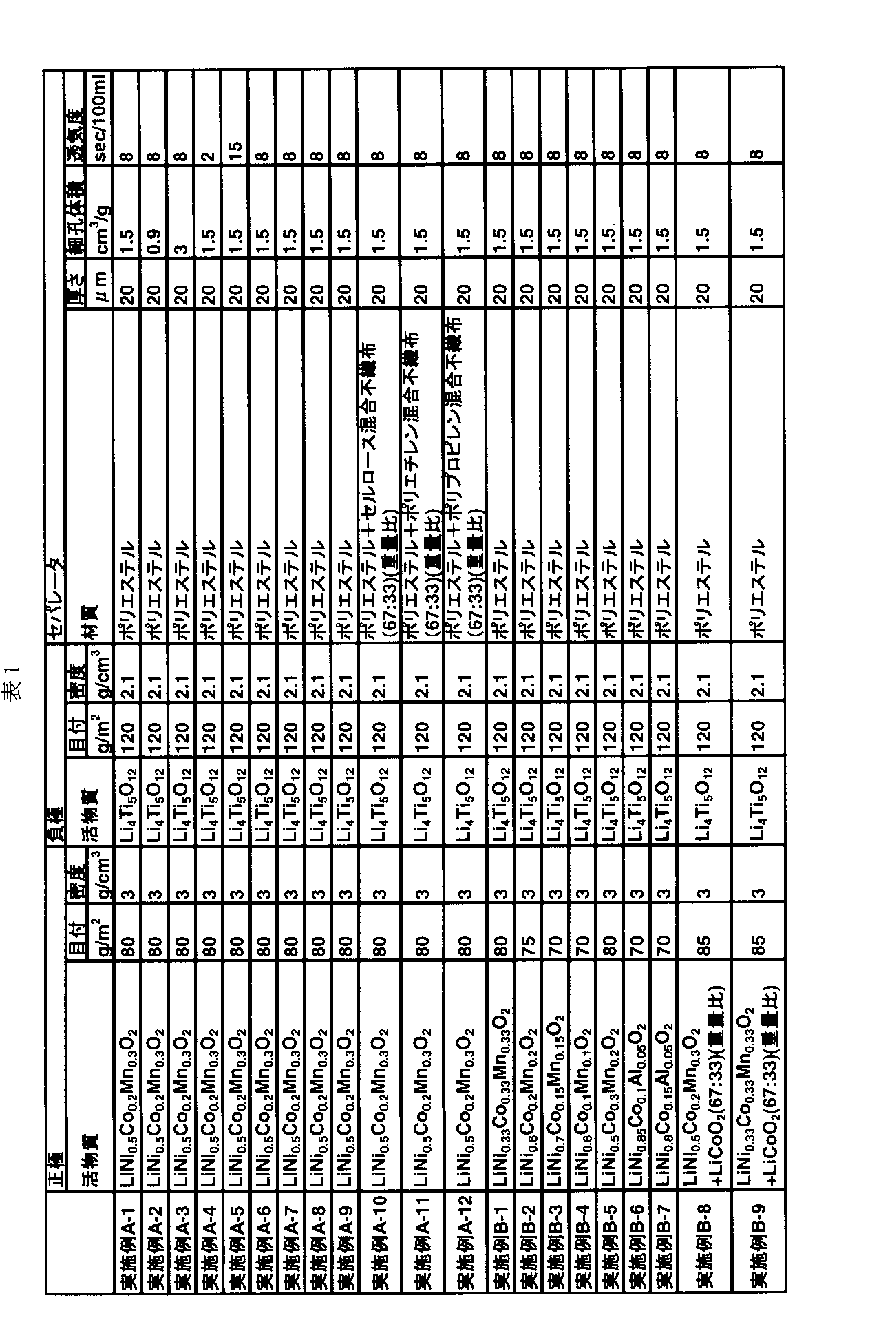
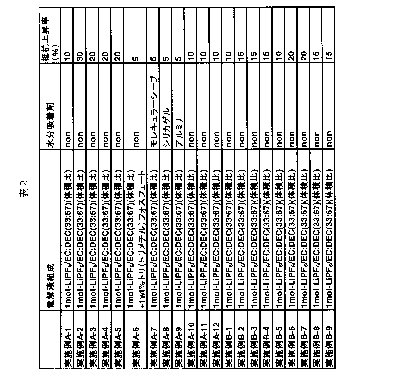
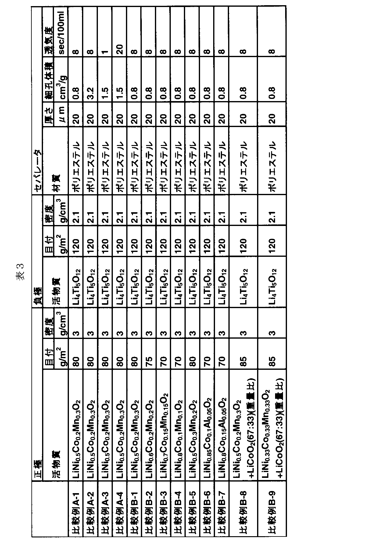
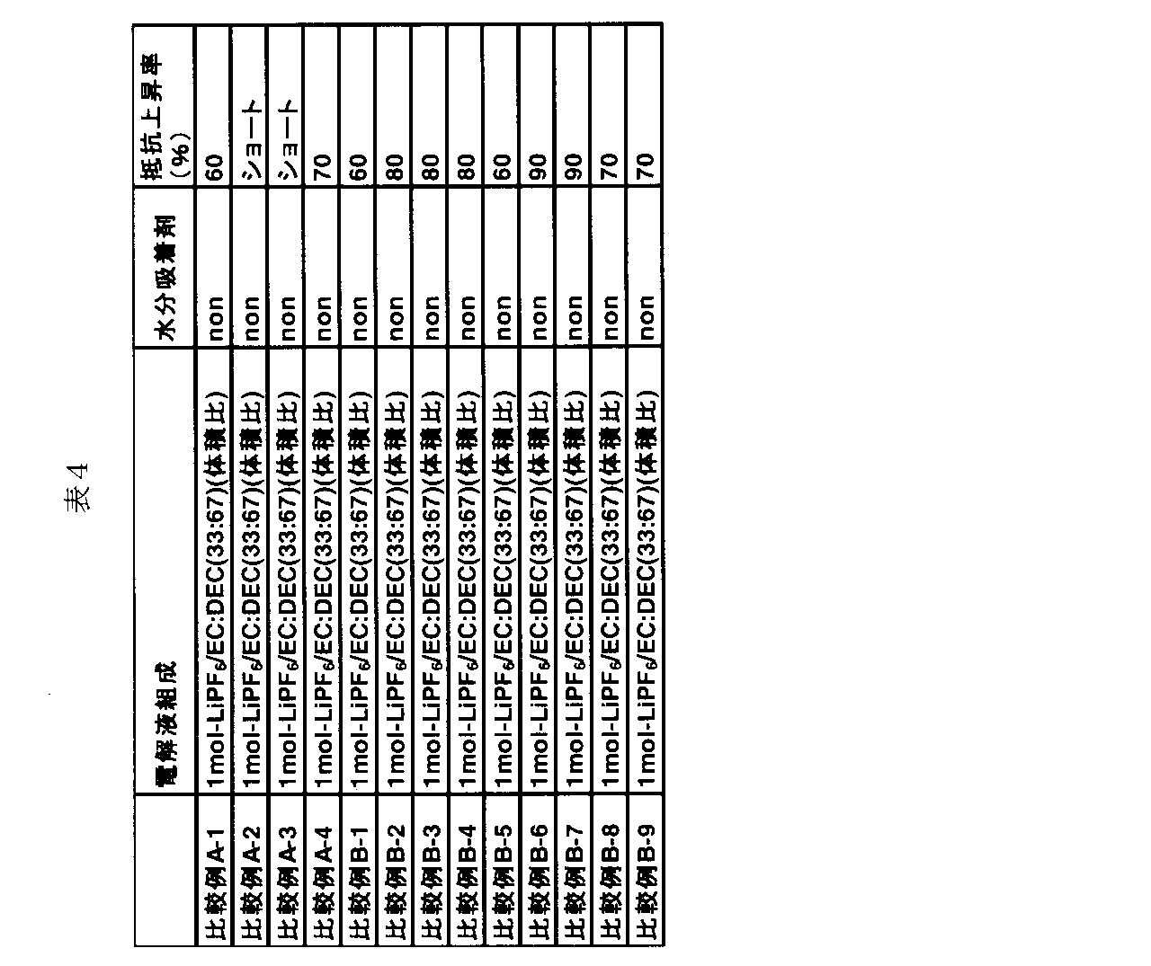
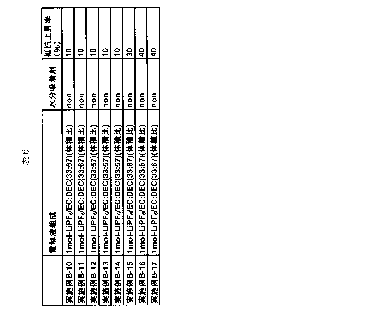
- Tables 1 to 4 show the separator material, thickness, pore volume in pore size distribution measurement by mercury intrusion method, air permeability by Gurley method, electrolyte composition, presence or absence of moisture adsorbent in battery, and configuration of positive electrode.
- a secondary battery was made in the same manner as in Example A1 except that what was shown was used.
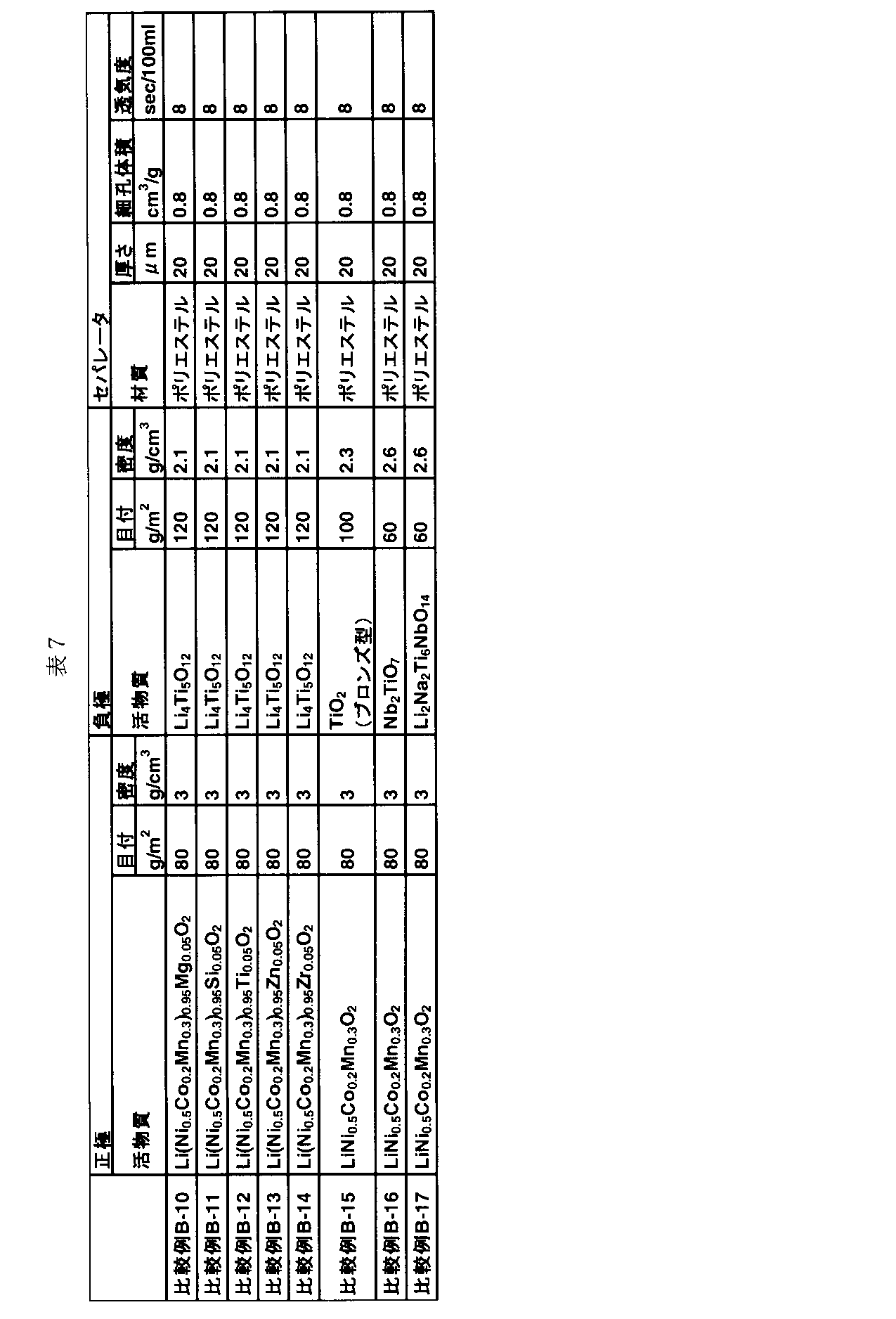
- Example 5 shows separator material, thickness, pore volume in pore size distribution measurement by mercury intrusion method, air permeability by Gurley method, electrolyte composition, presence or absence of moisture adsorbent in battery, positive electrode configuration and negative electrode configuration.
- a secondary battery similar to Example A1 was produced except that the battery shown in Table 8 was used.
- the moisture adsorbents of Examples A-7 to A-9 were placed in the cell by the following method.
- the moisture adsorbent molecular sieve, silica gel, and alumina powder were vacuum dried at 200 ° C. to remove moisture.
- the moisture adsorbent was placed in the cell.
- the obtained secondary battery was placed in a state of 50% depth of discharge (DOD: Depth of Discharge), measured for resistance in a 25 ° C. environment, left in a 70 ° C. environment for 30 days, and then measured for resistance in a 25 ° C. environment. The resistance increase rate was measured.
- DOD Depth of Discharge
- Example A-1 and Comparative Example A-1 are shown in FIG.
- the horizontal axis represents the pore diameter ( ⁇ m)
- the vertical axis represents the pore volume (cm 3 g).
- the separator used in the battery of Example A-1 had a larger volume of pores having a pore diameter of 1 ⁇ m or less than that of Comparative Example A-1.
- the pore volume was 0 when the air permeability was a constant value in the range of 2 sec / 100 ml to 15 sec / 100 ml. According to .9cm 3 / g or more 3 cm 3 / g the following examples a-1 ⁇ a-3, the resistance after the high temperature storage pore volume than the Comparative example a-1 of less than 0.9 cm 3 / g It was found that the rate of increase was small. Further, Comparative Example A-2 having a pore volume exceeding 3 cm 3 / g caused an internal short circuit due to high temperature storage.
- the pore volume is constant within a range of 0.9 cm 3 / g to 3 cm 3 / g.
- the air permeability is 2 sec / 100 ml or more and 15 sec / 100 ml or less
- the air permeability is higher than that of Comparative Example A-4 in which the air permeability exceeds 15 sec / 100 ml.
- Comparative Example A-3 having an air permeability of less than 2 sec / 100 ml caused an internal short circuit due to high temperature storage.
- a positive electrode containing Li x Ni 1-ab Co a Mn b M c O 2 and a pore volume of 0.9 cm 3 / g or more In the range of 3 cm 3 / g or less, the air permeability is in the range of 2 sec / 100 ml or more and 15 sec / 100 ml or less, and since the separator containing polyester is used, an increase in resistance after high-temperature storage can be suppressed. Long life can be obtained even in an environment.
- SYMBOLS 1 ... Exterior can, 2 ... Cover, 3 ... Positive electrode external terminal, 4 ... Negative electrode external terminal, 5 ... Electrode group, 6 ... Positive electrode, 6a ... positive electrode current collecting tab, 6b ... positive electrode material layer, 7 ... negative electrode, 7a ... negative electrode current collecting tab, 7b ... negative electrode material layer, 8 ... separator, 9 ... clamping member, 10 ... positive electrode lead, 11 ... negative electrode lead, 12 Insulating gasket, 21 unit cell, 22 assembled battery, 29 protective circuit, 30 thermistor.
Abstract
Description
(第一の実施形態)
発明者らは、LixNi1-a-bCoaMnbMcO2(0.9<x≦1.25、0<a≦0.4、0≦b≦0.45、0≦c≦0.1、MはMg,Al,Si,Ti,Zn,Zr,Ca及びSnよりなる群から選ばれる少なくとも1種の元素をあらわす)を含む正極活物質を含有する正極と、水銀圧入法による細孔径分布からの細孔体積が0.9~3cm3/gの範囲内で、ガーレー法による透気度(JIS-P-8117)が2~15sec/100mlの範囲内で、かつポリエステルを含むセパレータとを用いると、非水電解質電池の寿命特性が改善されることを見出した。
また、セパレータはポリエステルのみで形成されるものであってもいいが、ポリエステル以外にセルロース、ポリオレフィン、ポリアミド、ポリイミド及びポリビニルアルコールよりなる群から選ばれる少なくとも1種類のポリマーを含むことが好ましい。これは、ポリエステルが加水分解された場合においてもそれ以外の成分によってセパレータとしての形状を維持しやすいことで電池性能への悪影響を及ぼしにくいからである。
D=-4γcosθ/P (B)式
ここで、Pは加える圧力、Dは細孔直径、γは水銀の表面張力(480dyne・cm-1)、θは水銀と細孔壁面の接触角で140°である。γ、θは定数であるからWashburnの式より、加えた圧力Pと細孔直径Dの関係が求められ、そのときの水銀侵入体積を測定することにより、細孔直径とその体積分布を導くことができる。測定法・原理等の詳細は、非特許文献1(神保元ニら:「微粒子ハンドブック」朝倉書店(1991年))、非特許文献2(早川宗八郎編:「粉体物性測定法」朝倉書店(1973年))などを参照されたい。
パレータと、非水電解質とを具備する。
負極集電体には、例えば金属箔または合金箔が用いられる。集電体の厚さは、20μm以下、より好ましくは15μm以下であることが望ましい。金属箔としては銅箔、アルミニウム箔といったものが挙げられる。アルミニウム箔の場合、99重量%以上の純度を有することが好ましい。合金箔としてはステンレス箔、アルミニウム合金箔といったものが挙げられる。アルミニウム合金箔中のアルミニウム合金は、マグネシウム、亜鉛及びケイ素よりなる群から選ばれる少なくとも1種類の元素を含むことが好ましい。合金成分中の鉄、銅、ニッケル、クロムなどの遷移金属の含有量は1重量%以下にすることが好ましい。
正極活物質は、Li1-xNi1-a-b-cCoaMnbM1cO2(0.9<x≦1.25、0<a≦0.4、0≦b≦0.45、0≦c≦0.1、MはMg,Al,Si,Ti,Zn,Zr,Ca及びSnよりなる群から選ばれる少なくとも1種の元素をあらわす)を含む。正極活物質は、この酸化物のみであっても、他の種類の活物質を含んでいても良い。
この非水電解質は、非水溶媒と、この非水溶媒に溶解される電解質塩とを含むことができる。また、非水溶媒中にはポリマーを含んでもよい。
セパレータは、材料としてポリエステルを含んでいる。セパレータの材料は、ポリエステルのみであってもよく、あるいはポリエステルとポリエステル以外の材料との2種類以上を組み合わせて用いてもよい。ポリエステル以外の材料としては特に限定されないが、例えば、ポリオレフィン、セルロース、ポリエステル、ポリビニルアルコール、ポリアミド、ポリイミド、ポリテトラフルオロエチレン及びビニロンよりなる群から選ばれる少なくとも1種類のポリマーを挙げることができる。ポリエステル以外の材料のうち好ましいのは、セルロース、ポリオレフィン、ポリアミド、ポリイミド、ポリビニルアルコールである。
外装部材は、厚さ0.5mm以下のラミネートフィルム又は厚さ3mm以下の金属製容器が用いられる。金属製容器は、厚さ0.5mm以下であることがより好ましい。また、樹脂製容器を用いてもよい。樹脂製容器を形成する材料の例に、ポリオレフィン、ポリ塩化ビニル、ポリスチレン系樹脂、アクリル樹脂、フェノール樹脂、ポリフェニレン系樹脂、フッ素系樹脂等が含まれる。
負極端子は、アルミニウム、又は、Mg、Ti、Zn、Mn、Fe、Cu及びSiよりなる群から選択される少なくとも1種類の元素を含有するアルミニウム合金から形成することができる。負極集電体との接触抵抗を低減するために、負極端子は負極集電体と同様の材料から形成されることが好ましい。
正極端子は、アルミニウム、又は、Mg、Ti、Zn、Ni、Cr、Mn、Fe、Cu及びSiよりなる群から選択される少なくとも1種類の元素を含有するアルミニウム合金から形成されることが好ましい。正極集電体との接触抵抗を低減するために、正極端子は正極集電体と同様の材料から形成されることが好ましい。
(第2の実施形態)
第2の実施形態によれば、非水電解質電池を含む電池パックが提供される。非水電解質電池には、第1の実施形態に係る非水電解質電池が使用される。電池パックに含まれる非水電解質電池(単電池)の数は、1個または複数にすることができる。複数の単電池を備える場合、各単電池は電気的に直列もしくは並列に接続されている。
以下に実施例を説明するが、本発明の主旨を超えない限り、本発明は以下に記載される実施例に限定されるものではない。
(実施例A1)
<正極の作製>
正極活物質として、LiNi0.5Co0.2Mn0.3O2を準備した。また、導電剤として、グラファイト及びアセチレンブラックを準備した。そして、結着剤としてポリフッ化ビニリデン(PVdF)を準備した。次に、正極活物質、グラファイト、アセチレンブラック及びPVdFを混合して混合物を得た。この際、グラファイトは、作製する正極全体に対して2.5重量%の割合になるように添加した。アセチレンブラックは、作製する正極全体に対して2.5重量%の割合になるように添加した。PVdFは、作製する正極全体に対して5重量%となるように添加した。次に、得られた混合物をn-メチルピロリドン(NMP)溶媒中に分散して、スラリーを調製した。得られたスラリーを、厚さ15μmのアルミニウム箔に単位面積当たりの塗布量が80g/m2になるように塗布し、乾燥させた。次いで、乾燥させた塗膜をプレスした。かくして、正極材料層の目付量が80g/m2で、密度が3g/cm3である正極を作製した。
負極活物質として、スピネル型リチウムチタン複合酸化物Li4Ti5O12を準備した。また、導電剤としてグラファイトを準備した。そして、結着剤としてPVdFを準備した。次に、負極活物質、グラファイト、及びPVdFを混合して混合物を得た。この際、グラファイトは、作製する負極全体に対して3重量%になるように添加した。PVdFは、作製する負極全体に対して2重量%となるように添加した。次に、得られた混合物を、N-メチルピロリドン(NMP)溶液中で混合することによりスラリーを調製した。得られたスラリーを、厚さ15μmのアルミニウム箔からなる集電体に単位面積当たりの塗布量が120g/m2になるように塗布し、乾燥させた。次いで、乾燥させた塗膜をプレスして、集電体上に負極材料層を形成した。かくして、負極材料層の目付量が120g/m2で、密度が2.1g/cm3である帯状の負極を作製した。
33体積%のエチレンカーボネート(EC)及び67体積%のジエチルカーボネート(DEC)からなる非水溶媒中に、1MのLiPF6を混合して溶解させて、非水電解質として非水電解液を調製した。
厚さが20μmのポリエステルの不織布からなるセパレータを用意した。このセパレータの水銀圧入法による細孔径分布測定における細孔体積を前述の方法で求めたところ、1.5cm3/gであり、ガーレー法による透気度(JIS-P-8117)は8sec/100mlであった。
セパレータの材質、厚さ、水銀圧入法による細孔径分布測定における細孔体積、ガーレー法による透気度、電解液組成、電池中の水分吸着剤の有無、正極の構成を表1~表4に示すものを用いた以外が実施例A1と同様の二次電池を作製した。
セパレータの材質、厚さ、水銀圧入法による細孔径分布測定における細孔体積、ガーレー法による透気度、電解液組成、電池中の水分吸着剤の有無、正極の構成及び負極の構成を表5~表8に示すものを用いた以外が実施例A1と同様の二次電池を作製した。


6a…正極集電タブ、6b…正極材料層、7…負極、7a…負極集電タブ、7b…負極材
料層、8…セパレータ、9…挟持部材、10…正極リード、11…負極リード、12…絶
縁ガスケット、21…単電池、22…組電池、29…保護回路、30…サーミスタ。
Claims (8)
- LixNi1-a-bCoaMnbMcO2(0.9<x≦1.25、0<a≦0.4、0≦b≦0.45、0≦c≦0.1、MはMg,Al,Si,Ti,Zn,Zr,Ca及びSnよりなる群から選ばれる少なくとも1種の元素をあらわす)を含む正極活物質を含有する正極と、
負極と、
前記正極と前記負極の間に配置され、水銀圧入法による細孔径分布における細孔体積が0.9cm3/g以上3cm3/g以下の範囲内で、ガーレー法による透気度(JIS-P-8117)が2sec/100ml以上15sec/100ml以下の範囲内で、かつポリエステルを含むセパレータと、
非水電解質と
を含む、非水電解質電池。 - 前記セパレータは、セルロース、ポリオレフィン、ポリアミド、ポリイミド及びポリビニルアルコールよりなる群から選ばれる少なくとも1種類のポリマーを含む、請求項1に記載の非水電解質電池。
- 前記セパレータの厚さが3μm以上25μm以下の範囲内である、請求項2に記載の非水電解質電池。
- モレキュラーシーブ、シリカゲル及びアルミナよりなる群から選ばれる少なくとも一種類の水分吸着剤をさらに含む、請求項2に記載の非水電解質電池。
- 前記非水電解質は水分捕捉剤を含む、請求項2に記載の非水電解質電池。
- 前記負極は、スピネル型のチタン含有酸化物、アナターゼ型のチタン含有酸化物、ルチル型のチタン含有酸化物及びブロンズ型のチタン含有酸化物よりなる群から選ばれる少なくとも一種類の負極活物質を含む、請求項2に記載の非水電解質電池。
- 前記負極は、スピネル型のチタン含有酸化物、アナターゼ型のチタン含有酸化物、ルチル型のチタン含有酸化物、ブロンズ型のチタン含有酸化物、斜方晶型チタン含有酸化物及び単斜晶型ニオブチタン含有酸化物よりなる群から選ばれる少なくとも一種類の負極活物質を含む、請求項2に記載の非水電解質電池。
- 請求項1~7のいずれか1項に記載の非水電解質電池を含む電池パック。
Priority Applications (7)
| Application Number | Priority Date | Filing Date | Title |
|---|---|---|---|
| AU2015337606A AU2015337606B2 (en) | 2014-10-31 | 2015-10-30 | Nonaqueous electrolyte battery and battery pack |
| EP18210404.2A EP3474365B1 (en) | 2014-10-31 | 2015-10-30 | Electrode group comprising a positive electrode |
| CN201580041257.4A CN106663832B (zh) | 2014-10-31 | 2015-10-30 | 非水电解质电池及电池包 |
| EP15855003.8A EP3214689B1 (en) | 2014-10-31 | 2015-10-30 | Nonaqueous electrolyte battery and battery pack |
| JP2016556654A JP6226407B2 (ja) | 2014-10-31 | 2015-10-30 | 非水電解質電池及び電池パック |
| US15/453,623 US10541398B2 (en) | 2014-10-31 | 2017-03-08 | Nonaqueous electrolyte battery, battery pack and positive electrode |
| US16/708,559 US11362398B2 (en) | 2014-10-31 | 2019-12-10 | Nonaqueous electrolyte battery, battery pack and positive electrode |
Applications Claiming Priority (2)
| Application Number | Priority Date | Filing Date | Title |
|---|---|---|---|
| JP2014-223068 | 2014-10-31 | ||
| JP2014223068 | 2014-10-31 |
Related Child Applications (1)
| Application Number | Title | Priority Date | Filing Date |
|---|---|---|---|
| US15/453,623 Continuation US10541398B2 (en) | 2014-10-31 | 2017-03-08 | Nonaqueous electrolyte battery, battery pack and positive electrode |
Publications (1)
| Publication Number | Publication Date |
|---|---|
| WO2016068286A1 true WO2016068286A1 (ja) | 2016-05-06 |
Family
ID=55857619
Family Applications (1)
| Application Number | Title | Priority Date | Filing Date |
|---|---|---|---|
| PCT/JP2015/080725 WO2016068286A1 (ja) | 2014-10-31 | 2015-10-30 | 非水電解質電池及び電池パック |
Country Status (6)
| Country | Link |
|---|---|
| US (2) | US10541398B2 (ja) |
| EP (2) | EP3214689B1 (ja) |
| JP (2) | JP6226407B2 (ja) |
| CN (1) | CN106663832B (ja) |
| AU (1) | AU2015337606B2 (ja) |
| WO (1) | WO2016068286A1 (ja) |
Cited By (5)
| Publication number | Priority date | Publication date | Assignee | Title |
|---|---|---|---|---|
| CN109196694A (zh) * | 2016-07-29 | 2019-01-11 | 株式会社东芝 | 非水电解质电池及电池包 |
| CN109417193A (zh) * | 2016-07-29 | 2019-03-01 | 株式会社东芝 | 非水电解质电池及电池包 |
| CN110024197A (zh) * | 2016-12-26 | 2019-07-16 | 株式会社东芝 | 非水电解质电池及电池包 |
| JP2020528643A (ja) * | 2017-09-19 | 2020-09-24 | エルジー・ケム・リミテッド | リチウム二次電池用正極材、この製造方法、これを含むリチウム二次電池用正極、及びリチウム二次電池 |
| CN111801832A (zh) * | 2018-04-04 | 2020-10-20 | 株式会社东芝 | 非水电解质电池及电池包 |
Families Citing this family (8)
| Publication number | Priority date | Publication date | Assignee | Title |
|---|---|---|---|---|
| CN107431233B (zh) * | 2015-03-24 | 2020-09-08 | 日本电气株式会社 | 二次电池、二次电池的制造方法、电动车辆和蓄电系统 |
| CN107959053B (zh) * | 2017-11-28 | 2020-08-04 | 南开大学 | 改善高镍正极材料循环稳定性的功能性电解液及制备方法 |
| JP7163600B2 (ja) | 2018-03-16 | 2022-11-01 | ヤマハ株式会社 | 楽器用ピックアップ及び楽器 |
| CN108896618B (zh) * | 2018-06-28 | 2023-06-09 | 桑顿新能源科技(长沙)有限公司 | 一种检测锂离子电池正极极片残碱变化的方法及应用 |
| CN109265157B (zh) * | 2018-10-29 | 2022-01-21 | 惠州嘉科实业有限公司 | 具有v型引脚的低阻ntc热敏电阻及其制备方法 |
| US11121408B2 (en) | 2019-03-14 | 2021-09-14 | Medtronic, Inc. | Lithium-ion battery |
| US20230095171A1 (en) * | 2021-09-01 | 2023-03-30 | Enevate Corporation | Organic acid additives for silicon-based li ion batteries |
| CN116259927B (zh) * | 2023-05-15 | 2023-08-04 | 蔚来电池科技(安徽)有限公司 | 二次电池和装置 |
Citations (8)
| Publication number | Priority date | Publication date | Assignee | Title |
|---|---|---|---|---|
| JPS58155651A (ja) * | 1982-02-02 | 1983-09-16 | エムハート インダストリーズ インコーポレーテッド | 電池用セパレ−タ |
| JP2001126766A (ja) * | 1999-10-22 | 2001-05-11 | Sony Corp | 非水電解液二次電池 |
| JP2002319434A (ja) * | 2001-04-20 | 2002-10-31 | Sharp Corp | リチウムポリマー二次電池 |
| JP2008004536A (ja) * | 2006-05-22 | 2008-01-10 | Matsushita Electric Ind Co Ltd | セパレータおよび非水電解質二次電池 |
| JP2010065088A (ja) * | 2008-09-09 | 2010-03-25 | Toray Ind Inc | 多孔性フィルムおよび蓄電デバイス |
| JP2011233354A (ja) * | 2010-04-27 | 2011-11-17 | Nissan Motor Co Ltd | セパレータ |
| JP2014063753A (ja) * | 2013-12-03 | 2014-04-10 | Toshiba Corp | 非水電解質電池 |
| JP2014225372A (ja) * | 2013-05-16 | 2014-12-04 | 三菱製紙株式会社 | 電池用セパレータ |
Family Cites Families (22)
| Publication number | Priority date | Publication date | Assignee | Title |
|---|---|---|---|---|
| US4529677A (en) | 1982-02-02 | 1985-07-16 | Texon Incorporated | Battery separator material |
| US4618401A (en) | 1982-02-02 | 1986-10-21 | Texon, Inc. | Battery separator material |
| JPH11322988A (ja) * | 1998-05-18 | 1999-11-26 | Nitto Denko Corp | 多孔質フィルム並びにその製造と用途 |
| JP2001283821A (ja) | 2000-04-03 | 2001-10-12 | Mitsubishi Paper Mills Ltd | 非水電解液電池用セパレーターおよびそれを用いてなる非水電解液電池 |
| WO2001093350A1 (fr) * | 2000-05-29 | 2001-12-06 | Mitsubishi Paper Mills Limited | Separateur pour dispositif electrochimique, procede de production de ce dernier et dispositif electrochimique |
| JP2002190291A (ja) | 2000-12-22 | 2002-07-05 | Sumitomo Chem Co Ltd | セパレータおよびリチウムイオン二次電池 |
| JP2002280068A (ja) * | 2001-03-21 | 2002-09-27 | Matsushita Electric Ind Co Ltd | 非水電解質二次電池 |
| JP3765396B2 (ja) | 2001-08-20 | 2006-04-12 | ソニー株式会社 | 電池 |
| JP2006004536A (ja) | 2004-06-18 | 2006-01-05 | Seiko Epson Corp | 強誘電体メモリ装置及び電子機器 |
| JP2006019191A (ja) | 2004-07-02 | 2006-01-19 | Japan Vilene Co Ltd | リチウムイオン二次電池用セパレータ及びリチウムイオン二次電池 |
| FR2873497B1 (fr) | 2004-07-23 | 2014-03-28 | Accumulateurs Fixes | Accumulateur electrochimique au lithium fonctionnant a haute temperature |
| CN1744348A (zh) * | 2004-08-30 | 2006-03-08 | 北京东皋膜技术有限公司 | 用于锂离子二次电池的复合隔膜和具有该隔膜的锂离子二次电池 |
| KR101716907B1 (ko) * | 2008-08-19 | 2017-03-15 | 데이진 가부시키가이샤 | 비수계 2 차 전지용 세퍼레이터 |
| JP2011016973A (ja) * | 2009-07-07 | 2011-01-27 | Kee:Kk | 耐熱性複合ポリオレフィン微多孔膜及びその製造方法。 |
| EP2544290B1 (en) * | 2010-03-04 | 2018-04-25 | Kabushiki Kaisha Toshiba | Non-aqueous electrolyte cell, cell pack, and automobile |
| JP5575537B2 (ja) * | 2010-05-10 | 2014-08-20 | 日立マクセル株式会社 | 非水電解質電池 |
| JP5364801B2 (ja) | 2010-12-20 | 2013-12-11 | 日立マクセル株式会社 | 非水二次電池 |
| CN103314471B (zh) * | 2011-02-18 | 2015-11-25 | 株式会社东芝 | 正极、非水电解质电池及电池包 |
| KR101858968B1 (ko) * | 2012-03-30 | 2018-05-17 | 도레이 카부시키가이샤 | 폴리올레핀 다층 미다공막 |
| JP2014053259A (ja) * | 2012-09-10 | 2014-03-20 | Mitsubishi Paper Mills Ltd | リチウム二次電池用セパレータ及びリチウム二次電池 |
| JP2014192146A (ja) | 2013-03-28 | 2014-10-06 | Fujifilm Corp | 非水二次電池および非水二次電池用電解液 |
| JP6258082B2 (ja) | 2014-03-10 | 2018-01-10 | 株式会社東芝 | 非水電解質電池及び電池パック |
-
2015
- 2015-10-30 JP JP2016556654A patent/JP6226407B2/ja active Active
- 2015-10-30 WO PCT/JP2015/080725 patent/WO2016068286A1/ja active Application Filing
- 2015-10-30 AU AU2015337606A patent/AU2015337606B2/en active Active
- 2015-10-30 EP EP15855003.8A patent/EP3214689B1/en active Active
- 2015-10-30 EP EP18210404.2A patent/EP3474365B1/en active Active
- 2015-10-30 CN CN201580041257.4A patent/CN106663832B/zh active Active
-
2017
- 2017-03-08 US US15/453,623 patent/US10541398B2/en active Active
- 2017-09-22 JP JP2017182714A patent/JP6606144B2/ja active Active
-
2019
- 2019-12-10 US US16/708,559 patent/US11362398B2/en active Active
Patent Citations (8)
| Publication number | Priority date | Publication date | Assignee | Title |
|---|---|---|---|---|
| JPS58155651A (ja) * | 1982-02-02 | 1983-09-16 | エムハート インダストリーズ インコーポレーテッド | 電池用セパレ−タ |
| JP2001126766A (ja) * | 1999-10-22 | 2001-05-11 | Sony Corp | 非水電解液二次電池 |
| JP2002319434A (ja) * | 2001-04-20 | 2002-10-31 | Sharp Corp | リチウムポリマー二次電池 |
| JP2008004536A (ja) * | 2006-05-22 | 2008-01-10 | Matsushita Electric Ind Co Ltd | セパレータおよび非水電解質二次電池 |
| JP2010065088A (ja) * | 2008-09-09 | 2010-03-25 | Toray Ind Inc | 多孔性フィルムおよび蓄電デバイス |
| JP2011233354A (ja) * | 2010-04-27 | 2011-11-17 | Nissan Motor Co Ltd | セパレータ |
| JP2014225372A (ja) * | 2013-05-16 | 2014-12-04 | 三菱製紙株式会社 | 電池用セパレータ |
| JP2014063753A (ja) * | 2013-12-03 | 2014-04-10 | Toshiba Corp | 非水電解質電池 |
Non-Patent Citations (1)
| Title |
|---|
| See also references of EP3214689A4 * |
Cited By (13)
| Publication number | Priority date | Publication date | Assignee | Title |
|---|---|---|---|---|
| CN109417193B (zh) * | 2016-07-29 | 2021-10-15 | 株式会社东芝 | 非水电解质电池及电池包 |
| CN109417193A (zh) * | 2016-07-29 | 2019-03-01 | 株式会社东芝 | 非水电解质电池及电池包 |
| EP3493302A4 (en) * | 2016-07-29 | 2020-04-15 | Kabushiki Kaisha Toshiba | BATTERY WITH WATER-FREE ELECTROLYTE AND BATTERY PACK |
| CN109196694B (zh) * | 2016-07-29 | 2021-05-04 | 株式会社东芝 | 非水电解质电池及电池包 |
| CN109196694A (zh) * | 2016-07-29 | 2019-01-11 | 株式会社东芝 | 非水电解质电池及电池包 |
| US11239462B2 (en) | 2016-07-29 | 2022-02-01 | Kabushiki Kaisha Toshiba | Nonaqueous electrolyte battery and battery pack |
| CN110024197A (zh) * | 2016-12-26 | 2019-07-16 | 株式会社东芝 | 非水电解质电池及电池包 |
| EP3561935A4 (en) * | 2016-12-26 | 2020-07-22 | Kabushiki Kaisha Toshiba | CELL WITH WATER-FREE ELECTROLYTE AND CELL PACKAGE |
| US10964926B2 (en) | 2016-12-26 | 2021-03-30 | Kabushiki Kaisha Toshiba | Nonaqueous electrolyte battery and battery pack |
| CN110024197B (zh) * | 2016-12-26 | 2022-05-31 | 株式会社东芝 | 非水电解质电池及电池包 |
| JP2020528643A (ja) * | 2017-09-19 | 2020-09-24 | エルジー・ケム・リミテッド | リチウム二次電池用正極材、この製造方法、これを含むリチウム二次電池用正極、及びリチウム二次電池 |
| US11637275B2 (en) | 2017-09-19 | 2023-04-25 | Lg Energy Solution, Ltd. | Positive electrode material for lithium secondary battery, method of preparing the same, and positive electrode for lithium secondary battery and lithium secondary battery which include the positive electrode material |
| CN111801832A (zh) * | 2018-04-04 | 2020-10-20 | 株式会社东芝 | 非水电解质电池及电池包 |
Also Published As
| Publication number | Publication date |
|---|---|
| EP3474365B1 (en) | 2020-07-01 |
| US20170179486A1 (en) | 2017-06-22 |
| JPWO2016068286A1 (ja) | 2017-04-27 |
| CN106663832B (zh) | 2019-06-21 |
| CN106663832A (zh) | 2017-05-10 |
| EP3214689A4 (en) | 2018-05-02 |
| AU2015337606A1 (en) | 2017-03-30 |
| JP2018049828A (ja) | 2018-03-29 |
| US20200112011A1 (en) | 2020-04-09 |
| AU2015337606B2 (en) | 2019-01-31 |
| US10541398B2 (en) | 2020-01-21 |
| JP6606144B2 (ja) | 2019-11-13 |
| EP3474365A1 (en) | 2019-04-24 |
| JP6226407B2 (ja) | 2017-11-08 |
| US11362398B2 (en) | 2022-06-14 |
| EP3214689B1 (en) | 2019-01-23 |
| EP3214689A1 (en) | 2017-09-06 |
Similar Documents
| Publication | Publication Date | Title |
|---|---|---|
| JP6606144B2 (ja) | 非水電解質電池用電極群 | |
| US9406973B2 (en) | Nonaqueous electrolyte battery and battery pack | |
| JP6441125B2 (ja) | 非水電解質電池及び電池パック | |
| JP6250998B2 (ja) | 非水電解質電池及び電池パック | |
| JP6305112B2 (ja) | 非水電解質電池及び電池パック | |
| US10461314B2 (en) | Nonaqueous electrolyte battery and battery pack | |
| WO2015137138A1 (ja) | 非水電解質電池及び電池パック | |
| WO2016143123A1 (ja) | 非水電解質電池及び電池パック | |
| US11239457B2 (en) | Nonaqueous electrolyte battery and battery pack comprising a spinel type lithium-manganese composite oxide | |
| JP2014207238A (ja) | 非水電解質電池及び電池パック | |
| WO2019193690A1 (ja) | 非水電解質電池及び電池パック | |
| JP6054540B2 (ja) | 正極活物質、非水電解質電池及び電池パック | |
| JP5558498B2 (ja) | 非水電解質電池及び電池パック |
Legal Events
| Date | Code | Title | Description |
|---|---|---|---|
| 121 | Ep: the epo has been informed by wipo that ep was designated in this application |
Ref document number: 15855003 Country of ref document: EP Kind code of ref document: A1 |
|
| ENP | Entry into the national phase |
Ref document number: 2016556654 Country of ref document: JP Kind code of ref document: A |
|
| REEP | Request for entry into the european phase |
Ref document number: 2015855003 Country of ref document: EP |
|
| WWE | Wipo information: entry into national phase |
Ref document number: 2015855003 Country of ref document: EP |
|
| ENP | Entry into the national phase |
Ref document number: 2015337606 Country of ref document: AU Date of ref document: 20151030 Kind code of ref document: A |
|
| NENP | Non-entry into the national phase |
Ref country code: DE |