WO2016067712A1 - 情報処理装置 - Google Patents
情報処理装置 Download PDFInfo
- Publication number
- WO2016067712A1 WO2016067712A1 PCT/JP2015/072872 JP2015072872W WO2016067712A1 WO 2016067712 A1 WO2016067712 A1 WO 2016067712A1 JP 2015072872 W JP2015072872 W JP 2015072872W WO 2016067712 A1 WO2016067712 A1 WO 2016067712A1
- Authority
- WO
- WIPO (PCT)
- Prior art keywords
- user
- image
- unit
- display
- face
- Prior art date
Links
Images


Classifications
-
- A—HUMAN NECESSITIES
- A63—SPORTS; GAMES; AMUSEMENTS
- A63F—CARD, BOARD, OR ROULETTE GAMES; INDOOR GAMES USING SMALL MOVING PLAYING BODIES; VIDEO GAMES; GAMES NOT OTHERWISE PROVIDED FOR
- A63F13/00—Video games, i.e. games using an electronically generated display having two or more dimensions
- A63F13/60—Generating or modifying game content before or while executing the game program, e.g. authoring tools specially adapted for game development or game-integrated level editor
- A63F13/65—Generating or modifying game content before or while executing the game program, e.g. authoring tools specially adapted for game development or game-integrated level editor automatically by game devices or servers from real world data, e.g. measurement in live racing competition
- A63F13/655—Generating or modifying game content before or while executing the game program, e.g. authoring tools specially adapted for game development or game-integrated level editor automatically by game devices or servers from real world data, e.g. measurement in live racing competition by importing photos, e.g. of the player
-
- H—ELECTRICITY
- H04—ELECTRIC COMMUNICATION TECHNIQUE
- H04N—PICTORIAL COMMUNICATION, e.g. TELEVISION
- H04N21/00—Selective content distribution, e.g. interactive television or video on demand [VOD]
- H04N21/40—Client devices specifically adapted for the reception of or interaction with content, e.g. set-top-box [STB]; Operations thereof
- H04N21/47—End-user applications
- H04N21/478—Supplemental services, e.g. displaying phone caller identification, shopping application
- H04N21/4788—Supplemental services, e.g. displaying phone caller identification, shopping application communicating with other users, e.g. chatting
-
- A—HUMAN NECESSITIES
- A63—SPORTS; GAMES; AMUSEMENTS
- A63F—CARD, BOARD, OR ROULETTE GAMES; INDOOR GAMES USING SMALL MOVING PLAYING BODIES; VIDEO GAMES; GAMES NOT OTHERWISE PROVIDED FOR
- A63F13/00—Video games, i.e. games using an electronically generated display having two or more dimensions
- A63F13/20—Input arrangements for video game devices
- A63F13/21—Input arrangements for video game devices characterised by their sensors, purposes or types
- A63F13/213—Input arrangements for video game devices characterised by their sensors, purposes or types comprising photodetecting means, e.g. cameras, photodiodes or infrared cells
-
- A—HUMAN NECESSITIES
- A63—SPORTS; GAMES; AMUSEMENTS
- A63F—CARD, BOARD, OR ROULETTE GAMES; INDOOR GAMES USING SMALL MOVING PLAYING BODIES; VIDEO GAMES; GAMES NOT OTHERWISE PROVIDED FOR
- A63F13/00—Video games, i.e. games using an electronically generated display having two or more dimensions
- A63F13/70—Game security or game management aspects
- A63F13/79—Game security or game management aspects involving player-related data, e.g. identities, accounts, preferences or play histories
-
- A—HUMAN NECESSITIES
- A63—SPORTS; GAMES; AMUSEMENTS
- A63F—CARD, BOARD, OR ROULETTE GAMES; INDOOR GAMES USING SMALL MOVING PLAYING BODIES; VIDEO GAMES; GAMES NOT OTHERWISE PROVIDED FOR
- A63F13/00—Video games, i.e. games using an electronically generated display having two or more dimensions
- A63F13/80—Special adaptations for executing a specific game genre or game mode
- A63F13/812—Ball games, e.g. soccer or baseball
-
- A—HUMAN NECESSITIES
- A63—SPORTS; GAMES; AMUSEMENTS
- A63F—CARD, BOARD, OR ROULETTE GAMES; INDOOR GAMES USING SMALL MOVING PLAYING BODIES; VIDEO GAMES; GAMES NOT OTHERWISE PROVIDED FOR
- A63F13/00—Video games, i.e. games using an electronically generated display having two or more dimensions
- A63F13/85—Providing additional services to players
- A63F13/87—Communicating with other players during game play, e.g. by e-mail or chat
-
- G—PHYSICS
- G06—COMPUTING; CALCULATING OR COUNTING
- G06T—IMAGE DATA PROCESSING OR GENERATION, IN GENERAL
- G06T11/00—2D [Two Dimensional] image generation
-
- G—PHYSICS
- G06—COMPUTING; CALCULATING OR COUNTING
- G06T—IMAGE DATA PROCESSING OR GENERATION, IN GENERAL
- G06T11/00—2D [Two Dimensional] image generation
- G06T11/60—Editing figures and text; Combining figures or text
-
- H—ELECTRICITY
- H04—ELECTRIC COMMUNICATION TECHNIQUE
- H04N—PICTORIAL COMMUNICATION, e.g. TELEVISION
- H04N21/00—Selective content distribution, e.g. interactive television or video on demand [VOD]
- H04N21/20—Servers specifically adapted for the distribution of content, e.g. VOD servers; Operations thereof
- H04N21/23—Processing of content or additional data; Elementary server operations; Server middleware
- H04N21/242—Synchronization processes, e.g. processing of PCR [Program Clock References]
-
- H—ELECTRICITY
- H04—ELECTRIC COMMUNICATION TECHNIQUE
- H04N—PICTORIAL COMMUNICATION, e.g. TELEVISION
- H04N21/00—Selective content distribution, e.g. interactive television or video on demand [VOD]
- H04N21/40—Client devices specifically adapted for the reception of or interaction with content, e.g. set-top-box [STB]; Operations thereof
- H04N21/41—Structure of client; Structure of client peripherals
- H04N21/422—Input-only peripherals, i.e. input devices connected to specially adapted client devices, e.g. global positioning system [GPS]
- H04N21/4223—Cameras
-
- H—ELECTRICITY
- H04—ELECTRIC COMMUNICATION TECHNIQUE
- H04N—PICTORIAL COMMUNICATION, e.g. TELEVISION
- H04N21/00—Selective content distribution, e.g. interactive television or video on demand [VOD]
- H04N21/40—Client devices specifically adapted for the reception of or interaction with content, e.g. set-top-box [STB]; Operations thereof
- H04N21/43—Processing of content or additional data, e.g. demultiplexing additional data from a digital video stream; Elementary client operations, e.g. monitoring of home network or synchronising decoder's clock; Client middleware
- H04N21/44—Processing of video elementary streams, e.g. splicing a video clip retrieved from local storage with an incoming video stream, rendering scenes according to MPEG-4 scene graphs
- H04N21/44008—Processing of video elementary streams, e.g. splicing a video clip retrieved from local storage with an incoming video stream, rendering scenes according to MPEG-4 scene graphs involving operations for analysing video streams, e.g. detecting features or characteristics in the video stream
-
- H—ELECTRICITY
- H04—ELECTRIC COMMUNICATION TECHNIQUE
- H04N—PICTORIAL COMMUNICATION, e.g. TELEVISION
- H04N21/00—Selective content distribution, e.g. interactive television or video on demand [VOD]
- H04N21/40—Client devices specifically adapted for the reception of or interaction with content, e.g. set-top-box [STB]; Operations thereof
- H04N21/43—Processing of content or additional data, e.g. demultiplexing additional data from a digital video stream; Elementary client operations, e.g. monitoring of home network or synchronising decoder's clock; Client middleware
- H04N21/44—Processing of video elementary streams, e.g. splicing a video clip retrieved from local storage with an incoming video stream, rendering scenes according to MPEG-4 scene graphs
- H04N21/4402—Processing of video elementary streams, e.g. splicing a video clip retrieved from local storage with an incoming video stream, rendering scenes according to MPEG-4 scene graphs involving reformatting operations of video signals for household redistribution, storage or real-time display
-
- H—ELECTRICITY
- H04—ELECTRIC COMMUNICATION TECHNIQUE
- H04N—PICTORIAL COMMUNICATION, e.g. TELEVISION
- H04N21/00—Selective content distribution, e.g. interactive television or video on demand [VOD]
- H04N21/40—Client devices specifically adapted for the reception of or interaction with content, e.g. set-top-box [STB]; Operations thereof
- H04N21/45—Management operations performed by the client for facilitating the reception of or the interaction with the content or administrating data related to the end-user or to the client device itself, e.g. learning user preferences for recommending movies, resolving scheduling conflicts
- H04N21/454—Content or additional data filtering, e.g. blocking advertisements
- H04N21/4545—Input to filtering algorithms, e.g. filtering a region of the image
- H04N21/45455—Input to filtering algorithms, e.g. filtering a region of the image applied to a region of the image
-
- H—ELECTRICITY
- H04—ELECTRIC COMMUNICATION TECHNIQUE
- H04N—PICTORIAL COMMUNICATION, e.g. TELEVISION
- H04N21/00—Selective content distribution, e.g. interactive television or video on demand [VOD]
- H04N21/40—Client devices specifically adapted for the reception of or interaction with content, e.g. set-top-box [STB]; Operations thereof
- H04N21/47—End-user applications
- H04N21/478—Supplemental services, e.g. displaying phone caller identification, shopping application
- H04N21/4781—Games
-
- H—ELECTRICITY
- H04—ELECTRIC COMMUNICATION TECHNIQUE
- H04N—PICTORIAL COMMUNICATION, e.g. TELEVISION
- H04N7/00—Television systems
- H04N7/14—Systems for two-way working
- H04N7/141—Systems for two-way working between two video terminals, e.g. videophone
- H04N7/147—Communication arrangements, e.g. identifying the communication as a video-communication, intermediate storage of the signals
-
- A—HUMAN NECESSITIES
- A63—SPORTS; GAMES; AMUSEMENTS
- A63F—CARD, BOARD, OR ROULETTE GAMES; INDOOR GAMES USING SMALL MOVING PLAYING BODIES; VIDEO GAMES; GAMES NOT OTHERWISE PROVIDED FOR
- A63F2300/00—Features of games using an electronically generated display having two or more dimensions, e.g. on a television screen, showing representations related to the game
- A63F2300/50—Features of games using an electronically generated display having two or more dimensions, e.g. on a television screen, showing representations related to the game characterized by details of game servers
- A63F2300/55—Details of game data or player data management
- A63F2300/5546—Details of game data or player data management using player registration data, e.g. identification, account, preferences, game history
-
- G—PHYSICS
- G06—COMPUTING; CALCULATING OR COUNTING
- G06T—IMAGE DATA PROCESSING OR GENERATION, IN GENERAL
- G06T2207/00—Indexing scheme for image analysis or image enhancement
- G06T2207/20—Special algorithmic details
- G06T2207/20112—Image segmentation details
- G06T2207/20132—Image cropping
-
- H—ELECTRICITY
- H04—ELECTRIC COMMUNICATION TECHNIQUE
- H04N—PICTORIAL COMMUNICATION, e.g. TELEVISION
- H04N21/00—Selective content distribution, e.g. interactive television or video on demand [VOD]
- H04N21/20—Servers specifically adapted for the distribution of content, e.g. VOD servers; Operations thereof
- H04N21/23—Processing of content or additional data; Elementary server operations; Server middleware
- H04N21/24—Monitoring of processes or resources, e.g. monitoring of server load, available bandwidth, upstream requests
- H04N21/2402—Monitoring of the downstream path of the transmission network, e.g. bandwidth available
Definitions
- the present invention relates to a technique for distributing a user's camera video.
- Patent Document 1 discloses that a distribution-source game device distributes information regarding a game play status to a reception-side game device, and a reception-side user participates in a game being executed on the distribution-source game device. We are proposing a game distribution system that can be used.
- the user may distribute the state of the image taken by the camera together with the game image being played by the user. Although it is so-called “face-off” distribution, the user can reduce the distance from the viewer by making a face-out, and can also lead to the acquisition of the number of viewers. Therefore, there is a need for a technology that effectively performs “face-up” distribution.
- an object of the present invention is to provide a technique for effectively distributing the state of a user.
- an information processing apparatus includes an image acquisition unit that acquires captured images from an imaging device, a face recognition unit that detects facial images of a plurality of users in the captured images, and a display A display user determining unit that determines a user to be included in the image, a face image cutting unit that cuts out a region including the determined user's face image from the captured image, and a display image generating unit that generates a display image including the cut out region And an instruction receiving unit for receiving instructions. Based on the instruction received by the instruction receiving unit, the display user determining unit determines a user to be included in the display image, and the face image cutting unit cuts out an area including the determined user's face image.
- This apparatus receives an image acquisition unit that acquires a captured image from an imaging device, a face recognition unit that detects facial images of a plurality of users in the captured image, and a predetermined voice command as a switching instruction of a user included in the display image.
- An instruction receiving unit a display user determining unit that determines a user to be included in the display image based on the switching instruction; a face image cutting unit that cuts out an area including the determined user's face image from the captured image;
- a display image generation unit that generates a display image including the region.
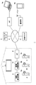
- FIG. 1 shows an information processing system 1 according to an embodiment of the present invention.
- the information processing system 1 realizes an environment in which a user who is a distributor distributes a game image being played live and another viewing user views the game image.
- the information processing system 1 includes an information processing device 10 used by a distribution user, a network server 5, a shared server 11, and various terminal devices 9a and 9b. These include the Internet, a LAN (Local Area Network), and a telephone network. Etc. are connected via the network 3.
- LAN Local Area Network
- An access point (hereinafter referred to as “AP”) 8 has a function of a wireless access point and a router, and the information processing apparatus 10 is connected to the AP 8 wirelessly or via a wire to connect to the network server 5 on the network 3,
- the shared server 11 is communicably connected.
- the information processing device 10 is connected to the input device 6 operated by the user wirelessly or by wire, and the input device 6 outputs information operated by the user to the information processing device 10.
- the information processing apparatus 10 receives the operation information from the input device 6, the information processing apparatus 10 reflects it in the processing of the system software or application software, and causes the output device 4 to output the processing result.
- the information processing device 10 is a game device that executes a game
- the input device 6 may be a device such as a game controller that supplies user operation information to the information processing device 10.
- the information processing device 10 distributes game image data being played to the terminal devices 9a and 9b in a streaming manner, and thus the information processing system 1 in the embodiment operates as a game image distribution system.
- the network server 5 provides a game network service to the user of the information processing apparatus 10.
- the network server 5 manages a network account for identifying the user, and the user signs in to a network service provided by the network server 5 using the network account. By signing in to the network service from the information processing apparatus 10, the user can register game save data and a virtual award (trophy) acquired during game play in the network server 5.
- terminal device 9 In this example, three users A, B, and C play a game together on the information processing apparatus 10, and the user A is the input device 6a, the user B is the input device 6b, and the user C is the input device 6c. Are operated respectively.
- a game image being played is displayed on the output device 4, and this game image is distributed to the viewing user's terminal devices 9 a and 9 b through the shared server 11.
- the terminal device 9a is a personal computer and is connected to the network 3 via an AP
- the terminal device 9b is a mobile device such as a smartphone and is connected to the network 3 via a base station.
- the viewing user may receive the game image distribution on the same terminal device as the information processing apparatus 10.
- the information processing device 10 and the terminal device may be connected by P2P to transmit / receive data to / from each other.
- the terminal of the viewing user is collectively referred to as “terminal device 9”.
- the auxiliary storage device 2 is a large-capacity storage device such as an HDD (hard disk drive) or a flash memory, and may be an external storage device connected to the information processing device 10 by a USB (Universal Serial Bus) or the like, and is a built-in storage device. There may be.
- the output device 4 may be a television having a display for outputting an image and a speaker for outputting sound, or may be a computer display.
- the output device 4 may be connected to the information processing device 10 with a wired cable or may be wirelessly connected.
- the input device 6 includes a plurality of input units such as a plurality of push-type operation buttons, an analog stick that can input an analog amount, and a rotary button.
- a camera 7 as an imaging device is provided in the vicinity of the output device 4 and images the space around the output device 4.
- FIG. 1 shows an example in which the camera 7 is attached to the upper part of the output device 4, the camera 7 may be arranged on the side of the output device 4, and in any case, the game is played in front of the output device 4. It arrange
- the camera 7 may be a stereo camera.
- camera image data obtained by photographing a user is distributed in real time to the terminal device 9 of the viewing user together with game image data played by the user. The camera image is superimposed on the game image and combined, or the camera image and the game image are combined so as not to overlap, and the combined image data is distributed to the terminal device 9.
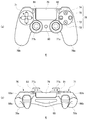
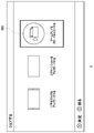
- FIG. 2A shows an external configuration of the upper surface of the input device.
- the user operates the input device 6 by holding the left grip 78b with the left hand and holding the right grip 78a with the right hand.
- On the upper surface of the housing, a touch pad 79 is provided in a flat area between the direction key 71 and the operation button 76.
- the touch pad 79 also functions as a push-down button that sinks downward when pressed by the user and returns to the original position when the user releases the hand.
- a function button 80 is provided between the two analog sticks 77a and 77b.
- the function button 80 is used to turn on the power of the input device 6 and simultaneously activate a communication function for connecting the input device 6 and the information processing device 10. After the input device 6 is connected to the information processing device 10, the function button 80 is also used to display a home screen on the information processing device 10.
- the SHARE button 81 is provided between the touch pad 79 and the direction key 71.
- the SHARE button 81 is used to input an instruction from the user to the OS or system software in the information processing apparatus 10.
- the OPTIONS button 82 is provided between the touch pad 79 and the operation button 76.
- the OPTIONS button 82 is used to input an instruction from the user to an application (game) executed in the information processing apparatus 10. Both the SHARE button 81 and the OPTIONS button 82 may be formed as push buttons.
- FIG. 2B shows an external configuration of the back side surface of the input device.
- a touch pad 79 extends from the upper surface of the casing on the upper side of the casing rear side of the input device 6, and a horizontally long light emitting unit 85 is provided on the lower side of the casing rear side.
- the light emitting unit 85 includes red (R), green (G), and blue (B) LEDs, and lights up according to light emission color information transmitted from the information processing apparatus 10.
- the information processing device 10 enables the users A, B, and C to distinguish the input devices 6 from each other.
- 6b, and 6c may be set to different colors, blue, red, and green, respectively.
- each user can recognize the input device 6 used by the user by the lighting color of the light emitting unit 85, and thus the possibility of mistaking the input device 6 is reduced.
- the upper button 83a, the lower button 84a, the upper button 83b, and the lower button 84b are provided at symmetrical positions in the longitudinal direction.
- the upper button 83a and the lower button 84a are operated by the index finger and middle finger of the user's right hand, respectively, and the upper button 83b and the lower button 84b are operated by the index finger and the middle finger of the user's left hand, respectively.
- the light emitting unit 85 is provided between the arrangement of the right upper button 83a and the lower button 84a and the arrangement of the left upper button 83b and the lower button 84b, so that an index finger for operating each button is provided.
- the camera 7 can capture an image of the light-emitting unit 85 that is lit.
- the upper button 83 may be configured as a push-type button
- the lower button 84 may be configured as a trigger-type button that is rotatably supported.
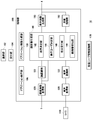
- FIG. 3 shows functional blocks of the information processing apparatus 10.
- the information processing apparatus 10 includes a main power button 20, a power ON LED 21, a standby LED 22, a system controller 24, a clock 26, a device controller 30, a media drive 32, a USB module 34, a flash memory 36, a wireless communication module 38, and wired communication.
- a module 40, a subsystem 50, and a main system 60 are included.
- the main system 60 includes a main CPU (Central Processing Unit), a memory and a memory controller that are main storage devices, a GPU (Graphics Processing Unit), and the like.
- the GPU is mainly used for arithmetic processing of game programs.
- the main CPU has a function of starting the OS and executing an application installed in the auxiliary storage device 2 in an environment provided by the OS.
- the subsystem 50 includes a sub CPU, a memory that is a main storage device, a memory controller, and the like, and does not include a GPU.
- the main CPU has a function of executing a game program installed in the auxiliary storage device 2 or the ROM medium 44, while the sub CPU does not have such a function.
- the sub CPU has a function of accessing the auxiliary storage device 2 and a function of transmitting and receiving data to and from the network server 5.
- the sub CPU is configured to have only such limited processing functions, and therefore can operate with less power consumption than the main CPU.
- the functions of these sub CPUs are executed when the main CPU is in a standby state.
- the information processing apparatus 10 since the subsystem 50 is operating when the main system 60 is in a standby state, the information processing apparatus 10 maintains a state where the network service provided by the network server 5 is always signed in.
- the main power button 20 is an input unit through which an operation input from a user is performed.
- the main power button 20 is provided on the front surface of the housing of the information processing apparatus 10 and turns on or off power supply to the main system 60 of the information processing apparatus 10. To be manipulated.
- the power ON LED 21 is lit when the main power button 20 is turned on, and the standby LED 22 is lit when the main power button 20 is turned off.
- the system controller 24 detects pressing of the main power button 20 by the user.
- the clock 26 is a real-time clock, generates current date and time information, and supplies it to the system controller 24, the subsystem 50, and the main system 60.
- the device controller 30 is configured as an LSI (Large-Scale Integrated Circuit) that exchanges information between devices like a South Bridge. As illustrated, devices such as a system controller 24, a media drive 32, a USB module 34, a flash memory 36, a wireless communication module 38, a wired communication module 40, a subsystem 50, and a main system 60 are connected to the device controller 30.
- the device controller 30 absorbs the difference in electrical characteristics of each device and the difference in data transfer speed, and controls the timing of data transfer.
- the media drive 32 is a drive device that loads and drives application software such as a game and a ROM medium 44 that records license information, and reads programs and data from the ROM medium 44.
- the ROM medium 44 is a read-only recording medium such as an optical disc, a magneto-optical disc, or a Blu-ray disc.
- the USB module 34 is a module that is connected to an external device with a USB cable.
- the USB module 34 may be connected to the auxiliary storage device 2 and the camera 7 with a USB cable.
- the flash memory 36 is an auxiliary storage device that constitutes an internal storage.
- the wireless communication module 38 wirelessly communicates with, for example, the input device 6 using a communication protocol such as a Bluetooth (registered trademark) protocol or an IEEE802.11 protocol.
- the wireless communication module 38 corresponds to the third generation (3rd Generation) digital mobile phone system conforming to the IMT-2000 (International Mobile Telecommunication 2000) standard defined by the ITU (International Telecommunication Union). It may also be compatible with another generation of digital mobile phone systems.
- the wired communication module 40 performs wired communication with an external device, and connects to the network 3 via, for example, the AP 8.
- FIG. 4 shows the configuration of the information processing apparatus 10 that operates as a streaming data distribution apparatus.
- the information processing apparatus 10 includes a processing unit 100, a communication unit 102, a reception unit 104, a microphone 110, and a registered user information holding unit 170.
- the processing unit 100 includes an application execution unit 106, an application image generation unit 108, a captured image acquisition unit 120, A face recognition unit 122, a voice acquisition unit 130, a voice recognition unit 132, a face image generation unit 140, a display image generation unit 160, and a sharing processing unit 162 are provided.
- the face image generation unit 140 includes an order determination unit 142, a display user determination unit 144, an instruction reception unit 146, and a face image cutout unit 148.
- each element described as a functional block for performing various processes can be configured by a circuit block, a memory, and other LSIs in terms of hardware, and loaded into the memory in terms of software. Realized by programs. Therefore, it is understood by those skilled in the art that these functional blocks can be realized in various forms by hardware only, software only, or a combination thereof, and is not limited to any one.
- the communication unit 102 receives the operation information of the input device 6 and distributes the content generated by the processing unit 100 to other terminal devices 9 via the shared server 11.
- a user of the terminal device 9 can access the shared server 11 connected to the network 3 and view content distributed from the information processing device 10.
- the content is a game image played by the users A, B, and C.
- the communication unit 102 is expressed as a configuration having the functions of the wireless communication module 38 and the wired communication module 40 shown in FIG. Note that the communication unit 102 may distribute the content directly to another terminal device 9.
- the accepting unit 104 is provided between the communication unit 102 and the processing unit 100 and transmits data or information between the communication unit 102 and the processing unit 100.
- the reception unit 104 supplies the operation information to the application execution unit 106, the face image generation unit 140, the shared processing unit 162, or the like in the processing unit 100.
- the reception unit 104 receives content from the display image generation unit 160 and provides the content to the communication unit 102.
- the registered user information holding unit 170 is formed in the storage area of the auxiliary storage device 2 and holds various information related to the user registered in the information processing device 10. Specifically, the registered user information holding unit 170 is associated with a user account and used for login. Registered user information includes a passcode, a sign-in ID for signing in to the network server 5, a network account, a user online ID (user name on the network), and a user icon for representing the user. ing. For registered users who have registered face images for face recognition processing in advance, the registered user information holding unit 170 holds face identification data as registered user information in association with the user account.
- the face identification data is the feature quantity data of the registered user's face image, but may be face image data itself.
- the face identification data is data to be compared in the face recognition process performed by the face recognition unit 122, and is generated according to a face recognition algorithm adopted by the face recognition unit 122.
- the face identification data may be data extracted as features of the relative positions and sizes of the parts of the face, and the shapes of eyes, nose, cheekbones and jaws.
- the face identification data may be data extracted as difference data from the standard data of the face image.
- the type of face identification data to be extracted is determined by the employed face recognition algorithm.
- the face recognition unit 122 employs a known face recognition algorithm. As for a registered user who has not registered a face image, naturally, the face identification data is not included in the registered user information holding unit 170.
- the application execution unit 106 executes a game program.
- the application execution unit 106 performs arithmetic processing for moving the game character in the virtual space based on the operation information input from the users A to C to the input devices 6a to 6c.
- the application execution unit 106 may be an application (game program) itself.
- the application image generation unit 108 may be a GPU (Graphics Processing Unit) that executes rendering processing or the like, and generates image data of an application (game) in response to a processing result by the application execution unit 106.
- the display image generation unit 160 outputs the game image generated by the application image generation unit 108 as it is as a display image from the output device 4 before the sharing process described later is started.
- FIG. 5 shows an example of a game screen displayed on the output device 4.
- the application execution unit 106 may execute an application other than the game, and the application image generation unit 108 may generate application image data other than the game.
- the sharing processing unit 162 of the embodiment realizes a function for sharing the game image data generated by the application image generating unit 108 with other users.
- This sharing process is triggered when one of the users A to C who is playing a game on the information processing apparatus 10 operates a specific input unit provided in the input apparatus 6, here the SHARE button 81. Run as.
- the sharing process is to make the screen displayed on the output device 4 in a state where another user can view it on the terminal device 9 or to actually view another screen on the terminal device 9. means.
- the user A operates the SHARE button 81 of the input device 6a will be described.
- the sharing processing unit 162 shares the game image data generated by the application image generating unit 108 with other users. Process to do. First, the sharing processing unit 162 generates an input image indicating options related to sharing of image data.
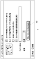
- FIG. 6 shows an example of an input screen showing options for sharing processing.
- this input screen three options related to content sharing are shown.
- “Upload a video clip” is a GUI designating that the image data recorded in the auxiliary storage device 2 is uploaded to the shared server 11, and “Upload a screen shot” is for uploading the screen shot image data to the shared server 11.
- the GUI for designating uploading to the game “Broadcast game play”, is a GUI for designating live broadcast of game play video via the shared server 11.
- the user A operates the input device 6a to move the frame 200, selects one of the GUIs, and presses the enter button, thereby executing the selected sharing process.
- FIG. 7 shows an example of a setting screen displayed when “Broadcast game play” is selected.
- This setting screen includes items for setting the broadcast mode.
- the user A agrees to at least “include the video of the camera in the broadcast”, and the video of the camera 7 is distributed together with the play video of the game.
- the display image generation unit 160 When “include camera video in broadcast” is selected, the display image generation unit 160 generates a display image obtained by synthesizing the game screen and the camera video, outputs the display image from the output device 4, and the sharing processing unit 162. Encodes the display image generated by the display image generation unit 160 and distributes it as a distribution image. Therefore, in the sharing process, the same screen as the screen viewed by the play user is distributed to the viewing user.
- the game image is shared via the shared server 11, but the game image may be distributed to the terminal device 9 by P2P.
- the display image generation unit 160 generates a display image in which a game image is arranged in the first area and a camera image is arranged in the second area. As will be described below, the display image generation unit 160 may set the second area within the first area, or set the first area and the second area so as not to overlap. May be. The position where the second area is set with respect to the first area depends on the distribution mode of the camera video.
- the sharing processing unit 162 allows the user to select the distribution mode of the camera video.
- a comment display field is created at a position that does not overlap the game screen. That is, in the display image generated by the display image generation unit 160, the game screen is slightly reduced and displayed, and the camera video and the comment display column are arranged in the margin portion resulting from the reduction.
- “display comment on screen” “set camera video overlay mode” is grayed out so that it cannot be selected.
- the display image generation unit 160 arranges the game image with the first area as a full screen, and displays the camera video in the second area in the first area.
- sharing processing unit 162 displays a setting screen that allows the user to set the camera video superimposition mode. It is displayed on the output device 4.
- FIG. 8 shows an example of a screen for setting a camera video superposition mode.
- this setting screen at least the position, size and aspect ratio for embedding the camera video in the game screen can be selected, and the camera video corresponding to the selected position, size and aspect ratio is displayed on the preview screen.
- the camera video is superimposed on the game screen in this way, the camera video is embedded in a partial area of the game screen displayed on the full screen.
- Three “Size” options are available: Small, Medium, and Large. Two of wide may be prepared.
- the aspect ratio expresses the aspect ratio of the camera image. For example, a camera image frame of 1: 1 is set for “normal” and 9:16 for “wide”.
- “Background” and “Effect” items are prepared as processing modes.
- the “Background” item indicates whether or not the user's background included in the camera image is to be changed.
- the “Effect” item is used to apply an effect to the camera image. If it is applied, the user can select which effect to apply.
- the “background” item is set to “not change” and the “effect” item is set to “none”, the camera video clipped about the user is embedded in the game screen as it is.
- the screen When the user presses the enter button, the screen returns to the setting screen shown in FIG. 7, but the distribution mode of the camera video set by the user is provided to the display image generation unit 160, and the display image generation unit 160 is in this distribution mode. Therefore, a display image in which the camera video is embedded in the game screen is generated.
- the setting screen shown in FIG. 8 can be called by the user by operating the function button 80 even after the sharing process is started, so that the superposition mode of the camera video can be reset during the sharing process. Good. In the following example, a case will be described in which the user has selected to superimpose the camera video on the upper right area of the game screen.
- the reception unit 104 notifies the sharing processing unit 162 of the start of broadcasting.
- the sharing processing by the sharing processing unit 162 is started, the face recognition processing by the face recognition unit 122 is started.
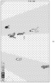
- FIG. 9 shows an example of a space photographed by the camera 7.
- the captured image acquisition unit 120 acquires captured image data from the camera 7.
- the camera 7 images a space periodically (for example, every 1/30 seconds) and provides the captured image to the captured image acquisition unit 120 via the USB module 34.
- the face recognition unit 122 detects a plurality of user face images in the captured image.
- the face recognizing unit 122 detects and extracts a portion estimated to be a human face in the captured image, derives feature amount data of the portion, and performs face identification for holding in the registered user information holding unit 170. Compared with the data, it is determined whether or not the extracted face is the face of the registered user.
- the face recognition unit 122 derives the degree of coincidence between the feature amount data of the extracted user's face image and the face identification data of all registered users held in the registered user information holding unit 170. This degree of coincidence is expressed numerically. For example, the degree of coincidence is derived in the form of how many points out of 100 points. If the degree of coincidence with the feature amount data of the registered face image exceeds 90 points, the face recognition unit 122 determines that the imaged user is a registered user, and determines which imaged user is Identify whether you are a registered user. If there are a plurality of items with a degree of coincidence exceeding 90 points, the face recognition unit 122 may determine that the imaged user is a registered user of face identification data from which the highest score is derived. .
- the face recognition unit 122 determines that the user included in the captured image is not the user who registered the face image. In this manner, the face recognition unit 122 detects the registered user's face image existing in the captured image using the face identification data held in the registered user information holding unit 170.
- this face identification technique a known technique may be used.
- FIG. 10 shows a face identification result by the face recognition unit 122.
- the face recognition unit 122 includes a face area 204a indicating a position in the captured image of the face of the user A, a face area 204b indicating a position in the captured image of the face of the user B, and a position in the captured image of the face of the user C.
- a face area 204c indicating “” is set by coordinates in the camera image.
- Each face area 204 may be set as a rectangular area that circumscribes the face image of the user.
- the face image generation unit 140 generates a face image to be combined with the game screen.
- the face image generation unit 140 switches the user's face image and provides it to the display image generation unit 160.
- the switching timing is when a predetermined command is input by the user.
- the face image is switched in accordance with a predetermined display order.
- the order determining unit 142 determines the display order of a plurality of users. For example, the first is set for the user A who has instructed the sharing process, and the second and later are set in the descending order of the face area 204. In the embodiment, all the users who play the game log in to the information processing apparatus 10, and the information processing apparatus 10 manages the input device 6 operated by each user and the user in association with each other. . Therefore, the information processing apparatus 10 knows that the user who has operated the SHARE button 81 is the user A, and the order determination unit 142 sets the user A to the first order.
- the order determination unit 142 compares the sizes of the face areas 204b and 204c of other users, that is, the users B and C, and sets the higher order in descending order. For example, if the face area 204c is larger than the face area 204b, the order determining unit 142 sets the user C in the second order and the user B in the third order. The comparison of the size of the face area 204 may be performed based on the area. The reason why the display order of the user with the larger face area 204 is higher is that the user who gets hot in the game tends to play at a position closer to the output device 4. Since it is considered that the player is playing at a position close to the output device 4, the display order is higher.
- the order determination unit 142 may set the order of users who register face images to be higher than the order of users who do not register face images.
- the order determination unit 142 may set the order of users facing the front to be higher than the order of users not facing the front.
- the orientation of the user's face may be detected by the face recognition unit 122 and notified to the order determination unit 142.
- the order determination unit 142 may set the order in the order from the shortest distance based on the actually measured distance from the camera 7. Since the camera 7 is a stereo camera, the order determining unit 142 may determine the order of the user by obtaining the distance between the camera 7 and the user from the two captured images.
- the captured image may include a user who is just watching the game play in addition to the play user.
- the face recognition unit 122 detects a face image in the captured image and sets the face region 204
- the order determination unit 142 is a display ordering target.
- the face recognition unit 122 detects whether the input device 6 exists below the face of the user whose face has been detected, and determines that it is a play user if it exists, and a non-play user if it does not exist. May be.
- the order determination unit 142 may set the order of the play user to be higher than the order of the non-play user.
- the first display order is set for the user A who operates the SHARE button 81.
- the order determination unit 142 determines that the order of the size of the face area 204 or the camera 7
- the display order of a plurality of users may be determined in the order of the shortest measured distances.
- the face image cutout unit 148 determines the cutout regions 206a to 206c of each user based on the face regions 204a to 204c set by the face recognition unit 122.
- the cut-out area 206 is an area cut out from the captured image when superimposed on the game screen, and includes a face area 204 of one user and is set to an area wider than the face area 204.
- the cutout area 206 is preferably set to a rectangular area obtained by expanding the face area 204 in the vertical and horizontal directions. By making the area wider than the face area 204, even if the user moves the face to some extent, the face is surely shot in the cutout area 206.
- the face recognition unit 122 always tracks (tracks) the user's face, but the face recognition process requires a large CPU load, so the tracking process may not be easy depending on the CPU power. Therefore, when the face recognition unit 122 does not track the user's face, the face image cutout unit 148 may fix the set cutout areas 206a to 206c and cut out the user's face image. Therefore, it is preferable that the face image cutout unit 148 sets the cutout area 206 wider.
- the order determination unit 142 orders the first user A, the second user C, and the third user B.
- the face recognition unit 122 specifies that the left user in the captured image is the user A, the middle user is the user B, and the right user is the user C.
- the order determining unit 142 can order No. 1 as user A, No. 2 as user C, and No. 3 as user B.
- a captured image may include a user who has not played or a user who has not registered a face image, and may not be able to specify who the captured user is. .
- the order determination unit 142 does not actually need to specify who the user is, the user of the detected face area 204a is the first, the user of the face area 204c is the second, and the user of the face area 204b Should be ordered as No. 3.
- the user of the detected face area 204a is called user A
- the user of the face area 204c is called user C
- the user of the face area 204b is called user B.
- the display user determination unit 144 determines users to be included in the display image generated by the display image generation unit 160.
- the display user determining unit 144 determines a user to be superimposed on the game screen according to the display order determined by the order determining unit 142.
- the face image cutout unit 148 cuts out an area including the face image of the user determined by the display user determining unit 144 from the captured image, and the display image generation unit 160 generates a display image including the cut out area.
- the display user determination unit 144 first determines the user A whose order is set to be the first as the display user, and notifies the face image cutout unit 148 of it.
- the face image cutout unit 148 cuts out the cutout area 206a of the user A from the captured image and provides it to the display image generation unit 160.
- the display image generation unit 160 also receives a game image from the application image generation unit 108.
- the display image generation unit 160 generates a display image in which the cut-out camera video is superimposed on an area on the game video according to the camera video superposition mode set in the sharing processing unit 162.
- the generated display image is output from the output device 4 and distributed to the shared server 11 by the sharing processing unit 162 via the communication unit 102.
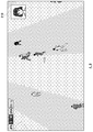
- FIG. 11 shows a game screen on which the camera video of user A is superimposed.
- the display area 210 designated by the superposition mode of the camera video the camera video cut out for the user A is displayed.
- This game screen is displayed on the output device 4 and also distributed to the terminal device 9 via the shared server 11.
- the viewing user can see the same game screen as the user who is playing the game.
- the voice acquisition unit 130 acquires the voice input to the microphone 110.
- Users A to C playing the game can switch the camera video displayed in the display area 210 by uttering a command.
- the user who speaks may be anyone or a user other than the play users A to C.
- the voice recognition unit 132 analyzes the voice acquired by the voice acquisition unit 130 and determines whether the command is a predetermined command.
- the voice recognition function of the voice recognition unit 132 is configured to detect a utterance of a predetermined word by the user, for example, “voice recognition on”, and by detecting the utterance of “voice recognition on”, a predetermined time, It is configured to be able to recognize other voices (words). That is, the voice recognition unit 132 detects the utterance of “voice recognition on”, and analyzes the voice acquired by the voice acquisition unit 130 within a predetermined time after the detection.
- the voice command for switching the camera video is “search for a face”, and when the voice recognition unit 132 detects that the user has uttered “search for a face”, the voice command recognizes the voice command,
- the instruction receiving unit 146 is notified that a voice command has been input.
- the instruction receiving unit 146 receives the voice command as a user switching instruction to be included in the display image.
- the display user determining unit 144 determines to switch the users included in the display image based on the switching instruction. Specifically, the display user determining unit 144 determines users to be included in the display image according to the display order determined by the order determining unit 142.
- the display user determination unit 144 determines the next user of the displayed user as the display user, and specifically determines the user C, which is the next user A, as the display user.
- the determined display user is notified to the face image cutout unit 148, and the face image cutout unit 148 cuts out the cutout area 206 c including the face image of the user C from the captured image and provides it to the display image generation unit 160.
- the display image generation unit 160 embeds the camera video of the cutout area 206c in the captured image in the display area 210 in the game screen, and generates a display image.
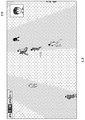
- FIG. 12 shows a game screen on which the camera video of user C is superimposed.
- a camera image cut out regarding the user C is displayed.
- This game screen is displayed on the output device 4 and also distributed to the terminal device 9 via the shared server 11.
- a voice command is sent to the instruction reception unit 146. Notify that it has been entered.
- the instruction receiving unit 146 receives the voice command as a user switching instruction to be included in the display image, and the display user determining unit 144 is determined by the order determining unit 142. Based on the determined order, it is determined to switch the users included in the display image.
- the display user determination unit 144 determines the next user of the displayed user as the display user, and specifically determines the user B, which is the next user C, as the display user.
- the determined display user is notified to the face image cutout unit 148, and the face image cutout unit 148 cuts out the cutout region 206 b including the face image of the user B from the captured image, and provides it to the display image generation unit 160.
- the display image generation unit 160 embeds the camera video of the cutout area 206b in the captured image in the display area 210 in the game screen, and generates a display image.
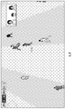
- FIG. 13 shows a game screen on which the camera image of user B is superimposed.
- a camera image cut out regarding the user B is displayed.
- the voice recognition unit 132 detects that the voice acquired by the voice acquisition unit 130 is “search for a face”, it notifies the instruction receiving unit 146 that a voice command has been input.
- the instruction receiving unit 146 receives the voice command as a user switching instruction to be included in the display image, and the display user determining unit 144 is determined by the order determining unit 142. Based on the determined order, it is determined to switch the users included in the display image.
- the display user determination unit 144 determines the next user as the display user.
- the display user determination unit 144 returns to the top and determines the display user. That is, when the user being displayed is the user C, there is no user in the next order, so the first user A is determined as the display user, and the face image cutout unit 148 displays the cutout area 206a of the user A. Is cut out from the captured image, and the display image generation unit 160 embeds the camera image of the cut-out area 206a in the captured image in the display area 210 in the game screen to generate a display image.
- the user can easily switch the camera image to be displayed.
- the viewing user can see the state of various users in the play environment and can feel the atmosphere of the play environment.
- the camera video is switched by the voice command, the user can use the input device 6 while concentrating on the game operation, and the camera video switching work can be easily realized.
- a switching instruction can be generated by a voice command.
- the instruction receiving unit 146 may receive a predetermined operation of the input device 6 as a camera video switching instruction.
- the information processing apparatus 10 does not include the microphone 110 and the voice recognition unit 132 cannot accept a voice command, it is effective to use a predetermined operation of the input device 6 as a camera image switching instruction.
- the coordinates of the set cutout areas 206a to 206c are fixed, and the cutout areas 206 included in the display image are sequentially switched according to the camera video switching instruction.
- the voice recognition function of the voice recognition unit 132 is configured to analyze voices of other utterances for a predetermined time when the user utters a predetermined word, when the voice recognition function is activated, the user When it is detected that “Search for” is uttered, the voice command is recognized, and the cutout area 206 included in the display image is switched.
- the voice recognition unit 122 may be instructed to execute the face recognition process, and the face recognition unit 122 may re-execute the face recognition process to reset the user's face area 204.
- the order determination unit 142 may re-decide the display order of a plurality of users, and the face image cutout unit 148 may reset the cutout area 206.
- the face recognition unit 122 preferably tracks the user's face and constantly updates the face area 204.
- the face image cutout unit 148 may acquire the coordinates of the face area 204 from the face recognition unit 122 and dynamically set the cutout area 206 according to the face area 204. Even in the case of tracking processing, the display order determined by the order determination unit 142 is fixed, and the camera video is still switched in the order of the user A, the user C, and the user B.
- the face recognition unit 122 can detect whether there is a change in the captured user configuration. For example, the user C may disappear from the angle of view of the camera 7 or a new user D may enter the angle of view of the camera 7.
- the face recognition unit 122 notifies the content of the change to the face image generation unit 140, whereby the order determination unit 142 updates the display order and also extracts the face image cutout.
- the part 148 preferably resets the cutout area 206.
- the case where a plurality of users are photographed has been described. However, only one user may be photographed.
- the voice recognition unit 132 detects that the voice acquired by the voice acquisition unit 130 is “search for a face”
- a voice command is input to the instruction reception unit 146.
- the face recognition unit 122 is instructed to execute face recognition processing. That is, when the number of users being photographed is one, the face recognition process by the face recognition unit 122 is re-executed and the face image cutout unit 148 is updated in order to reset the appropriate cutout region 206.
- An appropriate cutout area 206 may be set based on the face area 204 that has been set.
- the face image cutout unit 148 may cut the captured image in the cutout area 206 and then process the cutout image.
- the face image cutout unit 148 may process the camera video in the cutout area 206 in accordance with the contents of the “background” item and the “effect” item input on the camera video superposition mode setting screen shown in FIG. Good.
- the output unit 148 may provide the display image generation unit 160 with an icon, an avatar, or the like of the user instead of the cutout area 206 of the user.
- the user's face image is switched according to the display order determined by the order determination unit 142.
- the switching of the user's face image may be executed by explicitly specifying information for specifying the user.
- the instruction receiving unit 146 receives an instruction to specify a user
- the display user determining unit 144 determines to include the specified user in the display image.
- the user name of the user A is “Kate”
- the user name of the user B is “David”
- the user name of the user C is “Lucy”.
- the voice recognition unit 132 detects that the uttered voice is “Lucy” and notifies the instruction receiving unit 146 of it.
- the instruction receiving unit 146 receives the detected “Lucy” as an instruction for designating a user
- the display user determining unit 144 determines the user C who is “Lucy” as a display user
- the face image cutting unit 148 Then, the cutout area 206c of the user C is cut out and provided to the display image generation unit 160. Thereby, the user can specify the user who wants to display himself.
- the display user determination unit 144 may issue an identification word to the user who is photographed instead of the user name, and may determine the display user based on the identification word. For example, “player 1” is set for user A, “player 2” is set for user B, and “player 3” is set for user C. For example, the numbers may be determined in the order in which the input device 6 is connected to the information processing device 10.
- the voice recognition unit 132 detects that the uttered voice is “player 3” and notifies the instruction reception unit 146
- the instruction reception unit 146 uses the detected “player 3” as an instruction to specify the user.
- the reception and display user determination unit 144 determines the user C who is the “player 3” as a display user.
- the identification word is preferably a word with high recognition accuracy by the voice recognition unit 132.
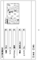
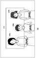
- FIG. 14 shows a screen display example of the user name and identification word.
- This screen is displayed on the output device 4 immediately after the face recognition processing by the face recognition unit 122 is completed, for example.
- both the user name and the identification word are displayed, but only one of them may be displayed.
- the user can confirm the user name or identification word by looking at this screen, and can efficiently switch the user's face image to be distributed by uttering the user name or identification word during game play. Will be able to.
- Such information may be displayed in a small area in an inconspicuous area such as the lower part of the game screen so that the user can confirm the user name or identification word even during game play.
- the display user is switched based on the voice command from the user (or the operation information of the input device 6).
- the display user determination unit 144 is based on the command from the user.
- the display user can be determined.
- the display user determination unit 144 may determine display users at regular intervals according to the display order of the plurality of users determined by the order determination unit 142. For example, the display user determination unit 144 switches the display user every 10 seconds. In this case, since the viewing user of the terminal device 9 can see all the users regarding the game play uniformly, the user can feel the atmosphere of the environment in which the user is playing.
- the sharing processing unit 162 may distribute the display image generated by the display image generation unit 160 with various information added thereto. For example, as information about the user included in the display image, personal information such as a user ID, user name, age, and trophy level, and information such as the number of users photographed by the camera 7 may be added. These pieces of information may be superimposed and distributed as text appears on the display image, or may be distributed as metadata.
- the user ID and the user name are useful as information for identifying the user included in the camera video. If all user IDs and user names photographed by the camera 7 are also distributed, the viewing user can know the existence of users not included in the camera video, and also convey the atmosphere of the play environment. Similarly, since the information on the number of users is information that informs the viewing user how many people are gathering, when there are a large number of users, it is possible to make the viewing user guess that there is an exciting atmosphere.
- the age and trophy level are information for determining whether the viewing user is playing a user at the same level as the viewing user. For example, when the viewing user is distributed as metadata, the viewing user can view the distribution game video on the shared server 11. It can also be used as a search key when selecting.
- the user can instruct the face image cutout unit 148 to replace it with another image.
- This instruction may be performed by a voice command or operation information of the input device 6.
- the instruction can be replaced with an image captured in the past, a camera image distributed in the past, or a user icon or avatar described above. Also good.
- the present invention has been described based on the embodiments. This embodiment is an exemplification, and it will be understood by those skilled in the art that various modifications can be made to the combination of each component and each processing process, and such modifications are also within the scope of the present invention. .
- the user's face image is superimposed on the game screen, but the user's face image may be displayed in a different area from the game screen.
- the switching instruction is performed by a voice command or operation information of the input device 6, but may be performed by a predetermined gesture of the user.
- FIG. 15 shows a face identification result by the face recognition unit 122.
- the face recognition unit 122 includes a face area 204 a that indicates a position in the captured image of the face of the user A, a face area 204 b that indicates a position in the captured image of the face of the user B, and the user A face area 204c indicating the position in the captured image of the face of C is set by coordinates in the camera image.
- the face image cutout unit 148 determines a cutout region 212 including the face regions 204a to 204c of all users based on the face regions 204a to 204c set by the face recognition unit 122. Since this cut-out area 212 includes the face images of all users, it is suitable for expressing the atmosphere during play.
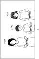
- FIG. 16 shows a game screen on which camera images including all users are superimposed.
- the viewing user can easily imagine what kind of atmosphere the game is played by looking at the camera video.
- the aspect ratio is preferably set to “wide” in the setting screen shown in FIG.
- the display order of the cutout areas 212 including the face images of all users may be determined by the order determining unit 142 together with the cutout areas 206 of the respective users.
- the order determining unit 142 sets No. 4 as all users A, B, and C while ordering No. 1 as user A, No. 2 as user C, and No. 3 as user B.
- the camera video of the cutout area 206a of the user A the camera video of the cutout area 206c of the user C
- the camera video of the cutout area 206b of the user B the users A, B, and C
- the camera images in the cutout area 212 are displayed in the order.
- the user can easily switch between the user's individual camera video and the camera video including a plurality of users simply by saying “search for a face”.
- the instruction receiving unit 146 receives a voice command that determines whether one user (one person mode) or all users (multiple modes) are included in the camera image to be distributed.
- the voice command designating the single mode is “one person”, and the voice command designating the multiple mode is “all”.
- the instruction receiving unit 146 receives the selection of the one-person mode and determines the display user.
- the unit 144 determines the display user in the single mode.
- the display user determination method in the single mode is as described in the embodiment.
- the voice recognizing unit 132 detects that the uttered voice is “all members” and notifies the instruction receiving unit 146
- the instruction receiving unit 146 receives the selection of the plurality of modes and determines the display user.
- the unit 144 notifies the face image cutout unit 148 that the multiple mode has been selected.
- the face image cutout unit 148 cuts out the cutout region 212 shown in FIG. 15 from the captured image and provides it to the display image generation unit 160.
- the user who is playing or the user in the play environment determines the user to be included in the display image based on the voice command and the operation information of the input device 6, but in the modification, the user of the terminal device 9 You may enable it to determine the user included in an image.
- the terminal device 9 when the terminal device 9 is the same terminal as the information processing device 10 and performs two-way communication, the terminal device 9 can directly transmit a command to the information processing device 10, and display user A command can be input to the determination unit 144 from the outside.
- the instruction receiving unit 146 may receive a switching instruction, and the display user determining unit 144 may switch the display user.
- the user of the terminal device 9 transmits a switching instruction specifying the user ID or the user name to the information processing apparatus 10. May be. Further, the user of the terminal device 9 may be able to transmit the switching instruction by designating the character in the game instead of the user name.
- the game specifies the user who is operating the forward, and the user ID is given to the display user determination unit 144 via the instruction reception unit 146.
- display user determination part 144 may determine the user who is operating forward as a display user. In this way, by installing the function of notifying the face image generation unit 140 of the user name on the game side, the viewing user can specify the user included in the camera video by specifying the character in the game. Become.
- the user of the terminal apparatus 9 may be able to designate the remote user. Since this remote user is not included in the captured image of the camera 7, the display user determining unit 144 transmits a camera activation request to the terminal device of the remote user, and the terminal device activates the camera to obtain the captured image information. By transferring to the processing device 10, the face image cutout unit 148 cuts out the face image of the remote user and provides it to the display image generation unit 160. Note that the remote user may transmit the captured image to the information processing apparatus 10 from another terminal such as a smartphone.
- DESCRIPTION OF SYMBOLS 1 ... Information processing system, 4 ... Output device, 6 ... Input device, 7 ... Camera, 9 ... Terminal device, 10 ... Information processing device, 11 ... Shared server, DESCRIPTION OF SYMBOLS 100 ... Processing part, 102 ... Communication part, 104 ... Reception part, 106 ... Application execution part, 108 ... Application image generation part, 110 ... Microphone, 120 ... Captured image Acquisition unit, 122 ... face recognition unit, 130 ... voice acquisition unit, 132 ... voice recognition unit, 140 ... face image generation unit, 142 ... order determination unit, 144 ... display user Determining unit, 146... Instruction receiving unit, 148... Face image cutting unit, 160... Display image generating unit, 162.
- the present invention can be used in the technical field of distributing camera images of users.
Abstract
Description
[上面部の構成]
図2(a)は、入力装置上面の外観構成を示す。ユーザは左手で左側把持部78bを把持し、右手で右側把持部78aを把持して、入力装置6を操作する。入力装置6の筐体上面には、入力部である方向キー71、アナログスティック77a、77bと、4種の操作ボタン76が設けられている。筐体上面上において、方向キー71と操作ボタン76の間の平坦な領域には、タッチパッド79が設けられる。タッチパッド79は、ユーザが押すことで下方に沈み込み、またユーザが手を離すと元の位置に復帰する押下式ボタンとしても機能する。
図2(b)は、入力装置奥側側面の外観構成を示す。入力装置6の筐体奥側側面の上側には、タッチパッド79が筐体上面から延設されており、筐体奥側側面の下側には、横長の発光部85が設けられる。発光部85は、赤(R)、緑(G)、青(B)のLEDを有し、情報処理装置10から送信される発光色情報にしたがって点灯する。図1に示すように、3台の入力装置6a、6b、6cが使用されている場合、情報処理装置10は、ユーザA、B、Cが各入力装置6を区別できるように、入力装置6a、6b、6cの発光部85の点灯色を異なる色、それぞれ青、赤、緑と定めてよい。これにより各ユーザは、自分が使用している入力装置6を発光部85の点灯色によって認識できるため、入力装置6を取り違える可能性が低減される。
図14は、ユーザ名、識別ワードの画面表示例を示す。この画面は、たとえば顔認識部122による顔認識処理が終了した直後に、出力装置4に表示される。この例では、ユーザ名と、識別ワードの双方が表示されているが、いずれか一方だけであってもよい。ユーザは、この画面を見ることで、ユーザ名ないし識別ワードを確認することができ、ゲームプレイ中に、ユーザ名ないし識別ワードを発声することで、配信するユーザの顔画像を効率的に切り替えることができるようになる。
図15は、顔認識部122による顔識別結果を示す。図10にも示したように、顔認識部122は、ユーザAの顔の撮像画像中の位置を示す顔領域204aと、ユーザBの顔の撮像画像中の位置を示す顔領域204bと、ユーザCの顔の撮像画像中の位置を示す顔領域204cとを、カメラ画像中の座標で設定する。
Claims (12)
- 撮像装置から撮像画像を取得する画像取得部と、
撮像画像において複数のユーザの顔画像を検出する顔認識部と、
表示画像に含めるユーザを決定する表示ユーザ決定部と、
撮像画像から、決定されたユーザの顔画像を含む領域を切り出す顔画像切出部と、
切り出した領域を含む表示画像を生成する表示画像生成部と、
指示を受け付ける指示受付部と、を備え、
前記指示受付部が受け付けた指示をもとに、前記表示ユーザ決定部が、表示画像に含めるユーザを決定して、前記顔画像切出部が、決定されたユーザの顔画像を含む領域を切り出すことを特徴とする情報処理装置。 - 前記顔画像切出部は、1人のユーザの顔画像を含む領域を切り出すことを特徴とする請求項1に記載の情報処理装置。
- 前記指示受付部は、表示画像に含めるユーザの切替指示を受け付け、前記表示ユーザ決定部は、切替指示をもとに、表示画像に含めるユーザを決定することを特徴とする請求項1または2に記載の情報処理装置。
- 複数のユーザの表示順序を決定する順序決定部を、さらに備え、
前記指示受付部がユーザの切替指示を受け付けると、前記表示ユーザ決定部は、表示順序にしたがって、ユーザを決定することを特徴とする請求項3に記載の情報処理装置。 - 前記指示受付部が、ユーザを指定する指示を受け付けると、前記表示ユーザ決定部が、指定されたユーザを表示画像に含めることを決定する、ことを特徴とする請求項1から3のいずれかに記載の情報処理装置。
- 撮像装置から撮像画像を取得する画像取得部と、
撮像画像において複数のユーザの顔画像を検出する顔認識部と、
所定の音声コマンドを、表示画像に含めるユーザの切替指示として受け付ける指示受付部と、
切替指示をもとに、表示画像に含めるユーザを決定する表示ユーザ決定部と、
撮像画像から、決定されたユーザの顔画像を含む領域を切り出す顔画像切出部と、
切り出した領域を含む表示画像を生成する表示画像生成部と、
を備えることを特徴とする情報処理装置。 - 前記表示画像生成部は、第1の領域にアプリケーション画像を配置し、第2の領域に切り出した領域を配置した表示画像を生成することを特徴とする請求項1から6のいずれかに記載の情報処理装置。
- 前記表示画像生成部は、第2の領域を、第1の領域内に設定することを特徴とする請求項7に記載の情報処理装置。
- 前記表示画像生成部は、第1の領域と第2の領域とが重ならないように設定することを特徴とする請求項7に記載の情報処理装置。
- 前記顔画像切出部は、複数のユーザの顔画像を含む領域を切り出すことを特徴とする請求項1から9のいずれかに記載の情報処理装置。
- コンピュータに、
撮像装置から撮像画像を取得する機能と、
撮像画像において複数のユーザの顔画像を検出する機能と、
指示を受け付ける機能と、
受け付けた指示をもとに、表示画像に含めるユーザを決定する機能と、
撮像画像から、決定されたユーザの顔画像を含む領域を切り出す機能と、
切り出した領域を含む表示画像を生成する機能と、
指示を受け付ける機能と、
を実現させるためのプログラム。 - 請求項11に記載のプログラムを記録したコンピュータ読み取り可能な記録媒体。
Priority Applications (2)
| Application Number | Priority Date | Filing Date | Title |
|---|---|---|---|
| KR1020177011615A KR102413269B1 (ko) | 2014-10-27 | 2015-08-12 | 정보 처리 장치 |
| US15/508,206 US11109108B2 (en) | 2014-10-27 | 2015-08-12 | Information processing device |
Applications Claiming Priority (2)
| Application Number | Priority Date | Filing Date | Title |
|---|---|---|---|
| JP2014218503A JP6396171B2 (ja) | 2014-10-27 | 2014-10-27 | 情報処理装置 |
| JP2014-218503 | 2014-10-27 |
Publications (1)
| Publication Number | Publication Date |
|---|---|
| WO2016067712A1 true WO2016067712A1 (ja) | 2016-05-06 |
Family
ID=55857059
Family Applications (1)
| Application Number | Title | Priority Date | Filing Date |
|---|---|---|---|
| PCT/JP2015/072872 WO2016067712A1 (ja) | 2014-10-27 | 2015-08-12 | 情報処理装置 |
Country Status (4)
| Country | Link |
|---|---|
| US (1) | US11109108B2 (ja) |
| JP (1) | JP6396171B2 (ja) |
| KR (1) | KR102413269B1 (ja) |
| WO (1) | WO2016067712A1 (ja) |
Families Citing this family (7)
| Publication number | Priority date | Publication date | Assignee | Title |
|---|---|---|---|---|
| CN105549814B (zh) * | 2015-12-01 | 2020-12-25 | 惠州Tcl移动通信有限公司 | 一种基于移动终端的拍照方法及该移动终端 |
| US10471353B2 (en) * | 2016-06-30 | 2019-11-12 | Sony Interactive Entertainment America Llc | Using HMD camera touch button to render images of a user captured during game play |
| KR101961241B1 (ko) * | 2017-09-07 | 2019-03-22 | 라인 가부시키가이샤 | 영상 통화 및 객체 인식을 바탕으로 한 게임 제공 방법 및 그 시스템 |
| JP6601513B2 (ja) | 2018-01-31 | 2019-11-06 | 日本電気株式会社 | 情報処理装置 |
| KR20210009596A (ko) * | 2019-07-17 | 2021-01-27 | 엘지전자 주식회사 | 지능적 음성 인식 방법, 음성 인식 장치 및 지능형 컴퓨팅 디바이스 |
| JP7390992B2 (ja) * | 2020-08-07 | 2023-12-04 | 株式会社ソニー・インタラクティブエンタテインメント | 情報処理装置および画像表示方法 |
| JP7244768B2 (ja) * | 2020-08-19 | 2023-03-23 | 株式会社カプコン | システム、サーバ及びプログラム |
Citations (3)
| Publication number | Priority date | Publication date | Assignee | Title |
|---|---|---|---|---|
| JP2012239719A (ja) * | 2011-05-20 | 2012-12-10 | Konami Digital Entertainment Co Ltd | ゲーム装置、ゲーム制御方法、ならびに、プログラム |
| JP2014155564A (ja) * | 2013-02-14 | 2014-08-28 | Namco Bandai Games Inc | ゲームシステム及びプログラム |
| JP2014191647A (ja) * | 2013-03-27 | 2014-10-06 | Konami Digital Entertainment Co Ltd | 情報処理装置、情報処理システム、情報処理方法、及びプログラム |
Family Cites Families (13)
| Publication number | Priority date | Publication date | Assignee | Title |
|---|---|---|---|---|
| JPH1051755A (ja) | 1996-05-30 | 1998-02-20 | Fujitsu Ltd | テレビ会議端末の画面表示制御装置 |
| JP2001305642A (ja) * | 2000-04-25 | 2001-11-02 | Fuji Photo Film Co Ltd | 撮像装置 |
| US9138644B2 (en) * | 2002-12-10 | 2015-09-22 | Sony Computer Entertainment America Llc | System and method for accelerated machine switching |
| CN101909156B (zh) | 2005-11-02 | 2013-01-16 | 奥林巴斯株式会社 | 电子照相机及其图像处理方法 |
| CN102231801B (zh) * | 2005-11-25 | 2013-07-10 | 株式会社尼康 | 电子摄像机及图像处理装置 |
| JP4794584B2 (ja) * | 2007-03-30 | 2011-10-19 | カシオ計算機株式会社 | 撮像装置、画像表示装置、及びそのプログラム |
| EP2263190A2 (en) * | 2008-02-13 | 2010-12-22 | Ubisoft Entertainment S.A. | Live-action image capture |
| US8128503B1 (en) * | 2008-05-29 | 2012-03-06 | Livestream LLC | Systems, methods and computer software for live video/audio broadcasting |
| KR101130564B1 (ko) * | 2009-12-11 | 2012-03-30 | 한국과학기술원 | 비디오 게임 콘솔 장치, 그 구동방법 및 컴퓨터 판독가능 매체 |
| WO2011112640A2 (en) * | 2010-03-08 | 2011-09-15 | Vumanity Media Llc | Generation of composited video programming |
| JP2012034793A (ja) | 2010-08-05 | 2012-02-23 | Sony Computer Entertainment Inc | ゲーム装置 |
| KR101710626B1 (ko) * | 2010-11-04 | 2017-02-27 | 삼성전자주식회사 | 디지털 촬영 장치 및 이의 제어 방법 |
| JP2013115527A (ja) * | 2011-11-28 | 2013-06-10 | Hitachi Consumer Electronics Co Ltd | テレビ会議システム及びテレビ会議方法 |
-
2014
- 2014-10-27 JP JP2014218503A patent/JP6396171B2/ja active Active
-
2015
- 2015-08-12 US US15/508,206 patent/US11109108B2/en active Active
- 2015-08-12 WO PCT/JP2015/072872 patent/WO2016067712A1/ja active Application Filing
- 2015-08-12 KR KR1020177011615A patent/KR102413269B1/ko active IP Right Grant
Patent Citations (3)
| Publication number | Priority date | Publication date | Assignee | Title |
|---|---|---|---|---|
| JP2012239719A (ja) * | 2011-05-20 | 2012-12-10 | Konami Digital Entertainment Co Ltd | ゲーム装置、ゲーム制御方法、ならびに、プログラム |
| JP2014155564A (ja) * | 2013-02-14 | 2014-08-28 | Namco Bandai Games Inc | ゲームシステム及びプログラム |
| JP2014191647A (ja) * | 2013-03-27 | 2014-10-06 | Konami Digital Entertainment Co Ltd | 情報処理装置、情報処理システム、情報処理方法、及びプログラム |
Also Published As
| Publication number | Publication date |
|---|---|
| JP6396171B2 (ja) | 2018-09-26 |
| US20170289633A1 (en) | 2017-10-05 |
| KR102413269B1 (ko) | 2022-06-27 |
| US11109108B2 (en) | 2021-08-31 |
| JP2016083225A (ja) | 2016-05-19 |
| KR20170072233A (ko) | 2017-06-26 |
Similar Documents
| Publication | Publication Date | Title |
|---|---|---|
| JP6396171B2 (ja) | 情報処理装置 | |
| JP6743241B2 (ja) | 情報処理装置 | |
| US11571620B2 (en) | Using HMD camera touch button to render images of a user captured during game play | |
| US10137361B2 (en) | Systems and methods for using reduced hops to generate an augmented virtual reality scene within a head mounted system | |
| US9908044B2 (en) | Information processing system and information processing apparatus | |
| WO2016080005A1 (ja) | プログラムおよび情報処理装置 | |
| JP2017182809A (ja) | 頭部装着ディスプレイにおけるオペレーション・モード・スイッチング | |
| US11534687B2 (en) | Information processing apparatus and application image distribution method | |
| JP6000929B2 (ja) | 情報処理装置 | |
| US10843071B2 (en) | Information processing apparatus, image data distribution method and program | |
| WO2018092535A1 (ja) | 情報処理装置、情報処理方法、およびプログラム | |
| KR20150004494A (ko) | 증강 현실 기반 소셜 미디어 플랫폼 시스템 및 컨텐츠 제공 방법 | |
| JP7300505B2 (ja) | 情報処理装置および画像表示方法 | |
| JP2022068190A (ja) | 情報処理装置およびゲーム画像表示方法 | |
| WO2017104578A1 (ja) | 情報処理装置およびコンテンツ画像提供方法 |
Legal Events
| Date | Code | Title | Description |
|---|---|---|---|
| 121 | Ep: the epo has been informed by wipo that ep was designated in this application |
Ref document number: 15855604 Country of ref document: EP Kind code of ref document: A1 |
|
| WWE | Wipo information: entry into national phase |
Ref document number: 15508206 Country of ref document: US |
|
| ENP | Entry into the national phase |
Ref document number: 20177011615 Country of ref document: KR Kind code of ref document: A |
|
| NENP | Non-entry into the national phase |
Ref country code: DE |
|
| 122 | Ep: pct application non-entry in european phase |
Ref document number: 15855604 Country of ref document: EP Kind code of ref document: A1 |