WO2016067655A1 - 変速機ケースおよびこれを備える変速機 - Google Patents
変速機ケースおよびこれを備える変速機 Download PDFInfo
- Publication number
- WO2016067655A1 WO2016067655A1 PCT/JP2015/059916 JP2015059916W WO2016067655A1 WO 2016067655 A1 WO2016067655 A1 WO 2016067655A1 JP 2015059916 W JP2015059916 W JP 2015059916W WO 2016067655 A1 WO2016067655 A1 WO 2016067655A1
- Authority
- WO
- WIPO (PCT)
- Prior art keywords
- case
- rib
- transmission
- partition member
- transmission case
- Prior art date
Links
Images


Classifications
-
- F—MECHANICAL ENGINEERING; LIGHTING; HEATING; WEAPONS; BLASTING
- F16—ENGINEERING ELEMENTS AND UNITS; GENERAL MEASURES FOR PRODUCING AND MAINTAINING EFFECTIVE FUNCTIONING OF MACHINES OR INSTALLATIONS; THERMAL INSULATION IN GENERAL
- F16H—GEARING
- F16H57/00—General details of gearing
- F16H57/02—Gearboxes; Mounting gearing therein
- F16H57/021—Shaft support structures, e.g. partition walls, bearing eyes, casing walls or covers with bearings
-
- F—MECHANICAL ENGINEERING; LIGHTING; HEATING; WEAPONS; BLASTING
- F16—ENGINEERING ELEMENTS AND UNITS; GENERAL MEASURES FOR PRODUCING AND MAINTAINING EFFECTIVE FUNCTIONING OF MACHINES OR INSTALLATIONS; THERMAL INSULATION IN GENERAL
- F16H—GEARING
- F16H57/00—General details of gearing
- F16H57/04—Features relating to lubrication or cooling or heating
- F16H57/045—Lubricant storage reservoirs, e.g. reservoirs in addition to a gear sump for collecting lubricant in the upper part of a gear case
- F16H57/0454—Sealings between different partitions of a gearing or to a reservoir
-
- F—MECHANICAL ENGINEERING; LIGHTING; HEATING; WEAPONS; BLASTING
- F16—ENGINEERING ELEMENTS AND UNITS; GENERAL MEASURES FOR PRODUCING AND MAINTAINING EFFECTIVE FUNCTIONING OF MACHINES OR INSTALLATIONS; THERMAL INSULATION IN GENERAL
- F16H—GEARING
- F16H57/00—General details of gearing
- F16H57/02—Gearboxes; Mounting gearing therein
- F16H2057/02008—Gearboxes; Mounting gearing therein characterised by specific dividing lines or planes of the gear case
-
- F—MECHANICAL ENGINEERING; LIGHTING; HEATING; WEAPONS; BLASTING
- F16—ENGINEERING ELEMENTS AND UNITS; GENERAL MEASURES FOR PRODUCING AND MAINTAINING EFFECTIVE FUNCTIONING OF MACHINES OR INSTALLATIONS; THERMAL INSULATION IN GENERAL
- F16H—GEARING
- F16H57/00—General details of gearing
- F16H57/02—Gearboxes; Mounting gearing therein
- F16H57/021—Shaft support structures, e.g. partition walls, bearing eyes, casing walls or covers with bearings
- F16H2057/0216—Intermediate shaft supports, e.g. by using a partition wall
-
- F—MECHANICAL ENGINEERING; LIGHTING; HEATING; WEAPONS; BLASTING
- F16—ENGINEERING ELEMENTS AND UNITS; GENERAL MEASURES FOR PRODUCING AND MAINTAINING EFFECTIVE FUNCTIONING OF MACHINES OR INSTALLATIONS; THERMAL INSULATION IN GENERAL
- F16H—GEARING
- F16H57/00—General details of gearing
- F16H57/02—Gearboxes; Mounting gearing therein
- F16H57/03—Gearboxes; Mounting gearing therein characterised by means for reinforcing gearboxes, e.g. ribs
-
- F—MECHANICAL ENGINEERING; LIGHTING; HEATING; WEAPONS; BLASTING
- F16—ENGINEERING ELEMENTS AND UNITS; GENERAL MEASURES FOR PRODUCING AND MAINTAINING EFFECTIVE FUNCTIONING OF MACHINES OR INSTALLATIONS; THERMAL INSULATION IN GENERAL
- F16H—GEARING
- F16H57/00—General details of gearing
- F16H57/04—Features relating to lubrication or cooling or heating
- F16H57/042—Guidance of lubricant
- F16H57/0421—Guidance of lubricant on or within the casing, e.g. shields or baffles for collecting lubricant, tubes, pipes, grooves, channels or the like
- F16H57/0424—Lubricant guiding means in the wall of or integrated with the casing, e.g. grooves, channels, holes
-
- F—MECHANICAL ENGINEERING; LIGHTING; HEATING; WEAPONS; BLASTING
- F16—ENGINEERING ELEMENTS AND UNITS; GENERAL MEASURES FOR PRODUCING AND MAINTAINING EFFECTIVE FUNCTIONING OF MACHINES OR INSTALLATIONS; THERMAL INSULATION IN GENERAL
- F16H—GEARING
- F16H57/00—General details of gearing
- F16H57/04—Features relating to lubrication or cooling or heating
- F16H57/0434—Features relating to lubrication or cooling or heating relating to lubrication supply, e.g. pumps ; Pressure control
- F16H57/0445—Features relating to lubrication or cooling or heating relating to lubrication supply, e.g. pumps ; Pressure control for supply of different gearbox casings or sections
Definitions
- the present invention relates to a transmission case capable of storing lubricating oil and a transmission including the same.
- Patent Document 1 discloses an input shaft, a counter shaft arranged in parallel to the input shaft, an output shaft arranged adjacent to the same straight line as the input shaft, an input shaft, and a counter A transmission case that houses a gear mechanism that selectively connects each of a shaft and an output shaft is disclosed.
- the transmission case described in the publication has a partition that divides the inside of the transmission case in the longitudinal direction, and the partition is integrally formed in the longitudinal center of the transmission case.
- the input shaft and the counter shaft are supported by the partition wall, so that the shaft support rigidity is increased and the bending rigidity of the transmission case itself is increased.
- the transmission case described above has a structure in which a partition wall is integrally formed in the central portion in the longitudinal direction, it is necessary to divide and form the transmission case into three parts: a clutch housing, a case body, and an end cover. , The mating surface between cases will increase. Thereby, the location which requires a seal
- a configuration in which a partition formed separately from the transmission case is incorporated and fixed inside the transmission case to suppress the number of divisions of the transmission case and reduce the mating surface between the cases is also conceivable.
- the present invention has been made in view of the above, and an object of the present invention is to provide a technology capable of both reducing the risk of oil leakage and improving the lubrication performance.
- the transmission case of the present invention and the transmission including the same employ the following means in order to achieve the above-described object.
- a transmission case capable of storing lubricating oil is configured.
- the transmission case is attached to the first case member, the second case member connected to the first case member, and the second case member, and the first case member side and the second case member are installed in the transmission case.
- a partition member that divides into a side. At least one of the second case member and the partition member is formed with a closing portion that closes a gap between the second case member and the partition member at least in a lower portion of the transmission case where lubricating oil is stored.
- the closed portion is formed typically corresponds to a mode in which the closed portion is integrally formed with the second case member or the partition member, but the closed portion is the second case member. And an embodiment in which the second case member and the partition member are integrated with each other after being molded separately from the partition member.
- the partition member since the partition member is mounted in the second case member, it is not necessary to divide the transmission case into three parts as in the conventional configuration in which the partition member is integrally formed with the transmission case.
- the number of mating surfaces of the case members constituting the transmission case can be suppressed. That is, since the number of sealing surfaces for preventing leakage of the lubricating oil stored in the transmission case can be reduced, the risk of oil leakage can be reduced.
- the partition wall member is mounted in the second case member, a gap formed between the second case member and the partition wall member is closed, and at least a lower portion of the transmission case in which lubricating oil is stored by the sealing portion. Therefore, at least in the lower part of the transmission case, the lubricating oil passes through the gap from the first case member side to the second case member side, or from the second case member side to the first case member side. It is possible to suppress free movement to Thereby, since it is possible to suppress the occurrence of insufficient lubricating oil on the first case member side and the second case member side, it is possible to improve the lubricating performance.
- the second case member has a longitudinal direction.
- the closing portion has a rib extending from at least one of the second case member and the partition member toward the partition member or the second case member facing each other in the longitudinal direction. Then, the second case member and the partition wall are brought into contact by bringing the leading end portion of the rib into contact with the end face of the partition member or the second case member facing the leading end portion of the rib, or by bringing the leading end portions of the ribs into contact with each other. It is comprised so that the clearance gap between members may be plugged up.
- the “extending toward the partition member or the second case member facing in the longitudinal direction” is typically in a direction along the longitudinal direction toward the partition member or the second case member.
- the extending aspect corresponds to this.
- the outer shape of the partition wall member and the inner shape of the second case member In addition to requiring high dimensional accuracy, it is difficult to attach the partition member to the inside of the second case member.
- the partition member and the second case member are brought into contact with each other via the rib in the mounting direction of the partition member to the second case member, that is, the longitudinal direction of the second case member. Therefore, the outer shape of the partition member and the inner shape of the second case member do not require high dimensional accuracy, and the attachment property of the partition member to the inside of the second case member does not deteriorate.
- the rib extends in the direction along the longitudinal direction of the second case member, that is, the direction along the casting direction when forming the internal space of the second case member, the inside of the second case member The rib can be formed at the same time as the space is formed, and even if the rib is provided on the second case member side, the productivity of the second case member is not lowered.
- the rib is configured to be along the outer edge of the partition wall member. According to this embodiment, since the gap between the second case member and the partition member is closed in the vicinity of the outer edge of the partition member, the gap between the outer peripheral surface of the partition member and the inner peripheral surface of the second case member is passed. Thus, the amount of lubricating oil entering the second case member can be minimized.
- the rib is formed so that the height in the vertical direction is at least equal to or higher than the height of the oil surface of the lubricating oil in the steady state.
- the “up and down direction” in the present invention corresponds to a direction substantially along the vertical direction of the transmission case in a state where the transmission including the transmission case is mounted on the vehicle.
- the “steady state” in the present invention corresponds to a state in which the oil level of the lubricating oil stored in the transmission case is stable, and the oil level is stable in a state parallel to the horizontal plane.
- the case where the oil level is stable in a state inclined with respect to the horizontal plane is suitably included.
- “when the oil level is stable in an inclined state with respect to the horizontal plane” typically means that a vehicle equipped with a transmission having the transmission case travels at a constant acceleration / deceleration. This corresponds to the oil level when the vehicle is running and the oil level when the vehicle is traveling on an uphill / downhill.
- the aspect “formed to a height equal to or higher than the oil level of the lubricating oil” includes the aspect in which the rib has a height that changes in accordance with the oil surface shape, and the oil having the highest rib.
- the aspect which has fixed height more than the height of a surface is included suitably. According to this form, it can suppress that lubricating oil moves to the 2nd case member side beyond a rib at least in a steady state.
- the partition member is configured to support a rotating body capable of scooping up lubricating oil.
- the rib is formed to the position where the height of the up-down direction of the part located in the rotation direction front side of a rotary body is higher than the vertical height of the part located in the rotation direction rear side of a rotary body.
- the support rigidity can be improved as compared with the structure in which the rotating body is supported only by the first case member or the second case member.
- the height position in the vertical direction of the front portion in the rotation direction of the rotating body is configured to be higher than the height position in the vertical direction of the rear portion in the rotation direction of the rotating body, Even when the oil level becomes higher than the oil level on the rear side in the rotation direction, it is possible to effectively suppress the lubricating oil from moving from the first case member side to the second case member side beyond the ribs.
- the partition member is configured to have a through-hole penetrating in the longitudinal direction at the lower part of the transmission case and above the closing part.
- the lubricating oil moves from the first case member side to the second case member side beyond the rib, the lubricating oil is transferred from the second case member side to the first case member side through the through hole. Can be returned.
- the second case member has a partition member mounting surface to which the partition member is mounted.
- the partition member has a second case member attachment surface that is attached to the partition member attachment surface. Then, the end of the rib and the end surface of the second case member or the partition member facing the tip of the rib, or the ends of the ribs are in contact with the partition member mounting surface and the second case member mounting surface. It is comprised so that it may contact
- machining for ensuring flatness can be simultaneously performed on the partition wall member mounting surface and the tip of the rib, and the second Machining for ensuring flatness can be simultaneously performed on the case member mounting surface and the end surface of the partition wall member where the tip of the rib contacts.
- the second case member mounting surface and the tip of the rib can be simultaneously machined to ensure flatness
- the partition member mounting surface and Of the two case members machining for ensuring flatness can be simultaneously performed on the end surface with which the tip of the rib contacts.
- machining for ensuring flatness may be simultaneously performed on the partition member mounting surface and the tip of the rib of the second case member.
- machining for ensuring flatness can be simultaneously applied to the second case member mounting surface and the tip of the rib of the partition wall member.
- workability can be improved.
- occlusion property of the clearance gap between a 2nd case member and a partition member can be improved.
- a gear mechanism capable of transmitting power to the output shaft via the counter shaft or directly and the transmission case of any of the above-described aspects are provided.
- At least one of the input shaft, the counter shaft, and the output shaft is supported by the partition member.
- the transmission case according to the present invention since the transmission case according to the present invention of any one of the aspects described above is provided, the same effects as the effects exhibited by the transmission case of the present invention, for example, the lubricating oil stored in the transmission case Since the number of sealing surfaces for preventing leakage can be reduced, the effect of reducing the risk of oil leakage and suppressing the occurrence of insufficient lubricating oil on the first case member side or the second case member side can be suppressed. As a result, the lubrication performance can be improved, the assembly performance and the productivity can be prevented, and the support rigidity of the input shaft, counter shaft and output shaft is improved. The effect which can be produced can be produced. As a result, the quality of the transmission itself can be improved and the reliability can be improved.
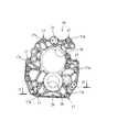
- FIG. 3 is a front view of an extension case 14.
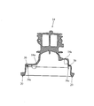
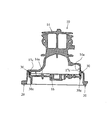
- FIG. 3 is a cross-sectional view taken along line AA in FIG. 2.
- FIG. 3 is a sectional view taken along line BB in FIG.
- FIG. 4 is a front view showing a state in which an adapter plate 16 is assembled to the extension case 14.
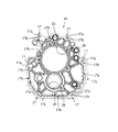
- 3 is a front view of an adapter plate 16.
- FIG. 6 It is the back view which looked at the adapter plate 16 from the back surface.
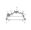
- FIG. 6 is a cross-sectional view taken along line EE in FIG. 5.
- FIG. 6 is a sectional view taken along line FF in FIG. 5.
- the transmission 1 includes an input shaft 2, a counter shaft 4 disposed in parallel with the input shaft 2, an output shaft 6 disposed coaxially with the input shaft 2, an input shaft 2 and a counter.
- a reduction gear mechanism RGM that connects the shaft 4
- a transmission mechanism TM that connects the input shaft 2 or the counter shaft 4 and the output shaft 6, a transmission case 10 according to the embodiment of the present invention that accommodates these, Is provided.
- the counter shaft 4 is an example of an implementation configuration corresponding to the “rotary body” and the “counter shaft” in the present invention.
- the reduction gear mechanism RGM and the speed change mechanism TM are examples of an implementation configuration corresponding to the “gear mechanism” in the present invention.
- the side where the input shaft 2 is arranged in the longitudinal direction of the transmission 1 (the lower side in the drawing in FIG. 1) is defined as “front side” or “front”, and the output shaft 6 1 is defined as “rear side” or “rear side”.
- the side on which the control rod 50 is disposed (left side in FIG. 1) is defined as “upper” or “upper”, and the side on which the counter shaft 4 is disposed (right side in FIG. 1) is defined as “lower” or “upper”. It is defined as “downward”.
- the input shaft 2 is a shaft to which power of an engine (not shown) is input via a clutch (not shown).
- a reduction drive gear RG is integrally formed at the rear end portion of the input shaft 2 (the portion opposite to the side where the clutch is disposed).
- the counter shaft 4 is rotatably supported by the transmission case 10 at the front end portion, the intermediate portion, and the rear end portion via bearings B2, B3, and B4, respectively.
- the front end portion of the counter shaft 4 is rotatably supported by the case body 12 via a bearing B2
- the intermediate portion of the counter shaft 4 is connected to an adapter plate 16 described later in the transmission case 10 via a bearing B3.
- the rear end portion of the counter shaft 4 is rotatably supported by an extension case 14 described later in the transmission case 10 via a bearing B4.
- the counter shaft 4 is supported by the transmission case 10 at three positions, that is, a front end portion, an intermediate portion, and a rear end portion. Thereby, the support rigidity of the counter shaft 4 is improved.
- a reduction driven gear RG ′ that meshes with the reduction drive gear RG is integrally formed at the front end portion of the counter shaft 4 and at the rear portion of the portion supported by the case body 12 by the bearing B2.
- the gear diameter of the reduction driven gear RG ' is formed larger than the gear diameter of the reduction drive gear RG.
- a reduction gear mechanism RGM is configured by the reduction driven gear RG ′ and the reduction drive gear RG.
- the output shaft 6 is a shaft for outputting power, and as shown in FIG. 1, one end is inserted into the input shaft 2 and is rotatably supported by the input shaft 2 via a pilot bearing PB.
- the intermediate portion is rotatably supported by the adapter plate 16 of the transmission case 10 via the bearing B5.
- the rear end portion of the output shaft 6 is supported by the extension case 14 via a sleeve yoke of a propeller shaft (not shown). That is, the output shaft 6 is supported by the transmission case 10 at three locations, that is, a front end portion, an intermediate portion, and a rear end portion. Thereby, the support rigidity of the output shaft 6 improves.
- the speed change mechanism TM includes a plurality of drive gears G provided on the counter shaft 4, a plurality of driven gears G ′ meshed with the drive gear G and provided on the output shaft 6, and a drive gear.
- G or driven gear G ′ a plurality of synchro mechanisms S for selectively fixing to the counter shaft 4 or the output shaft 6 a gear (spinning gear) provided to be rotatable relative to the counter shaft 4 or the output shaft 6; , Is composed of.
- the power transmitted to the counter shaft 4 is output to the output shaft 6 via the speed change mechanism TM.
- the transmission case 10 includes a case main body 12, an extension case 14 attached and fixed to the case main body 12 with bolts BLT, and an adapter plate 16 attached and fixed inside the extension case 14 with bolts (not shown). And.
- the lower part of the transmission case 10 constitutes a lubricating oil reservoir for storing lubricating oil.
- the components of the transmission 1 such as the input shaft 2, the counter shaft 4, the output shaft 6, the reduction gear mechanism RGM, the transmission mechanism TM, the bearings B1, B2, B3, B4, B5, and the pilot bearing PB are lubricated by the lubricating oil.
- the case body 12 corresponds to the “first case member” in the present invention
- the extension case 14 corresponds to the “second case member” in the present invention
- the adapter plate 16 corresponds to the “partition member” in the present invention. It is an example of the implementation structure to do.
- the case main body 12 is formed in a substantially drum shape with an opening on the front side and the rear side with a partition wall 12 c sandwiched between them, and a clutch for housing a clutch (not shown).
- the housing 12a and the components of the transmission 1 such as the input shaft 2, the counter shaft 4, the output shaft 6, the reduction gear mechanism RGM, the speed change mechanism TM, the bearings B1, B2, B3, B4, B5, and the pilot bearing PB are accommodated. It is comprised from the main-body part 12b which comprises the principal part of the accommodation space for doing.
- An attachment surface 13 for attaching and fixing the extension case 14 is formed at the rear opening end of the main body 12b.
- the clutch housing portion 12a, the main body portion 12b, and the partition wall portion 12c are integrally formed.
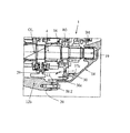
- the extension case 14 has an opening on the front side (the side attached to the case body 12, the lower side in FIGS. 1, 3 and 4).
- the outer shape is formed in a substantially conical shape whose diameter is gradually reduced toward the side (the upper side in FIGS. 1, 3 and 4).
- the extension case 14 has a through hole 15 into which the control rod 50 is inserted, a through hole 18 into which the output shaft 6 is inserted, and an insertion recess 19 into which the counter shaft 4 is inserted. Is formed.
- a mounting surface 20 that abuts on the mounting surface 13 of the case body 12 is formed. Furthermore, a plurality of mounting bosses 22 for mounting and fixing the adapter plate 16 are provided along the peripheral wall inner surface 14a at positions slightly inside in the radial direction from the peripheral wall inner surface 14a of the extension case 14.
- the mounting boss 22 has a contact surface 22a with which the adapter plate 16 contacts. As shown in FIG. 2, the contact surface 22 a faces the same direction as the direction in which the mounting surface 20 faces, that is, the longitudinal direction of the extension case 14.
- the contact surface 22a is an example of an implementation configuration corresponding to the “partition wall member mounting surface” in the present invention.
- the extension case 14 is formed with ribs 30 extending in the direction along the longitudinal direction of the extension case 14 from the peripheral wall inner surface 14 a toward the opening.
- the rib 30 is an example of the implementation structure corresponding to the "blocking part" and "rib" in this invention.
- the rib 30 is configured to extend in a direction along the casting direction when the internal space of the extension case 14 is formed, the rib 30 is formed at the same time as the internal space of the extension case 14 is formed. Can be molded. Thereby, the rib 30 can be shape
- FIG. 1 is configured to extend in a direction along the casting direction when the internal space of the extension case 14 is formed.
- the rib 30 is formed at a position lower than the lower portion of the extension case 14 (lower side in FIG. 2), specifically, the upper end portion of the through hole 18 into which the output shaft 6 is inserted. ing.
- the rib 30 is formed in a substantially inverted J shape in front view along the lower outer edge shape of the adapter plate 16. Specifically, the rib 30 starts from the mounting boss 22 disposed on the left side of the through hole 18 in FIG.
- the connection boss 22 is connected to the lower right side mounting boss 22 in FIG. 2 and the mounting boss 22 arranged on the right side in FIG.
- the rib 30 is configured such that one end 30 a becomes a height substantially corresponding to the center of the through hole 18 in consideration of the inclination in the rotational direction of the lubricating oil, as will be described later in detail.
- the other end 30 b is configured to be slightly lower than the center of the insertion recess 19.
- the other end 30b of the rib 30 is configured to be at a height position equal to or higher than the oil level of the lubricating oil in a static state.
- the extended tip portion 30 c of the rib 30 is configured to be flush with the contact surface 22 a of the mounting boss 22.
- the mounting bosses 22 arranged above the ribs 30 are configured as independent bosses as shown in FIG.
- the adapter plate 16 is configured as a plate-like member having a substantially elliptical shape that is substantially the same shape as the inner shape of the extension case 14 in front view (having a long axis in the vertical direction in FIG. 5).
- the adapter plate 16 not only improves the support rigidity of the counter shaft 4 and the output shaft 6, but also contributes to the improvement of the bending rigidity of the transmission case 10 itself.
- a through hole 24 into which the control rod 50 is inserted, a through hole 26 into which the output shaft 6 is inserted, and a counter shaft 4 are inserted into the adapter plate 16 in order from above.
- a through hole 28 is formed.
- the through holes 24, 26, and 28 are formed so as to be coaxial with the through holes 15 and 18 and the insertion recess 19 formed in the extension case 14, respectively.
- a plurality of mounting boss portions 17 are formed on the outer edge portion of the adapter plate 16 corresponding to the mounting bosses 22 of the extension case 14.
- the mounting boss portion 17 is formed with a through hole 17a for inserting a mounting bolt (not shown).
- the mounting boss portion 17 has a mounting surface 17b with which the contact surface 22a comes into contact.
- the mounting surface 17 b is formed in an annular shape continuously in the circumferential direction of the adapter plate 16, and connects the mounting boss portions 17 in the circumferential direction.
- the mounting surface 17b is an example of an implementation configuration corresponding to the “second case member mounting surface” in the present invention.
- the lower portion of the mounting surface 17b constitutes a contact surface 17c with which the extended tip portion 30c of the rib 30 in the extension case 14 contacts. Furthermore, in the lower part of the adapter plate 16, specifically, the part between the through hole 28 and the lowermost end part of the adapter plate 16, as shown in FIG. 6 and FIG. A hole 29 is formed.
- the contact surface 17c is an example of an implementation configuration corresponding to the “blocking portion” and the “end surface of the partition wall member” in the present invention.
- the adapter plate 16 is inserted into the extension case 14 from the opening side of the extension case 14, and the mounting surface 17b is in contact with the contact surface 22a and the contact surface 17c is
- the rib 30 is attached and fixed to the extension case 14 with a mounting bolt (not shown) in contact with the extended tip 30c of the rib 30.
- the adapter plate 16 since the outer shape of the adapter plate 16 is smaller than the inner shape in the portion from the opening of the extension case 14 to the contact surface 22a, the adapter plate 16 can be easily inserted into the extension case 14. be able to.
- the adapter plate 16 is formed separately from the case main body 12 and the extension case 14, and the adapter plate 16 formed separately is attached and fixed inside the extension case 14.
- the extension case 14 with the adapter plate 16 attached and fixed therein is attached and fixed to the case main body 12 with bolts BLT to constitute the transmission case 10.
- the transmission case 10 has only a single mating surface composed of the mounting surface 13 of the case body 12 and the mounting surface 20 of the extension case 14 that contacts the mounting surface 13.
- the transmission case 10 since the transmission case 10 has a configuration having only one sealing surface, the transmission case 10 is stored inside compared to a configuration in which the transmission case 10 is divided into three or more and has two or more sealing surfaces. It is possible to reduce the risk of leaked lubricating oil leaking to the outside.
- the adapter plate 16 is attached and fixed to the extension case 14, and the abutting surface 17c and the extended tip 30c are brought into contact with each other, whereby a lower portion of the extension case 14, specifically, the rib 30 is formed. A gap between the extension case 14 and the adapter plate 16 in the range thus formed is closed.
- a gap (a radial direction between the inner peripheral surface 14 a of the extension case 14 and the outer peripheral surface of the adapter plate 16 is provided between the extension case 14 and the adapter plate 16. And a gap extending in the longitudinal direction between the mounting surface 17b of the adapter plate 16 and the peripheral wall inner surface 14a of the extension case 14), and the inside of the body portion 12b of the case body 12
- the extension case 14 communicates with the inside.
- the lubricating oil is also inclined in the longitudinal direction (solid line OL in FIG. 11). Specifically, the lubricating oil is inclined so that the oil level OL on the rear side in the longitudinal direction (right side in FIG. 11) is higher than the oil level OL on the front side in the longitudinal direction (left side in FIG. 11) in the transmission case 10. To do.
- the contact between the contact surface 17c of the adapter plate 16 and the extended tip 30c of the rib 30 of the extension case 14 closes the gap in the lower portion between the adapter plate 16 and the extension case 14, Since the communication between the inside of the main body portion 12b of the case main body 12 and the inside of the extension case 14 is blocked, the movement of the lubricating oil from the main body portion 12b side to the extension case 14 side is suppressed (solid arrow in FIG. 11).
- the vertical height of the one end 30a of the rib 30 is configured to be a height position substantially corresponding to the center of the through hole 18, and thus the main body portion 12b. The movement of the lubricating oil from the side to the extension case 14 side can be effectively suppressed.
- the height of the one end 30a of the rib 30 is such that the oil level OL of the lubricating oil is inclined rearward in the rotational direction and the longitudinal direction when the vehicle on which the transmission 1 is mounted suddenly starts running at the first speed.
- the oil level is set to be higher than the oil level OL.
- the rib 30 is formed in a shape that follows the shape of the lower outer edge of the adapter plate 16, and is closer to the outer peripheral surface of the adapter plate 16, in other words, closer to the inner surface 14 a of the peripheral wall of the extension case 14. 14, the amount of lubricating oil flowing into the extension case 14 through the gap between the outer peripheral surface of the adapter plate 16 and the peripheral wall inner surface 14a of the extension case 14 is minimized. Can do. Thereby, the movement of the lubricating oil from the main body portion 12b side to the extension case 14 side can be more effectively suppressed.
- the other end 30b of the rib 30 is configured to be higher in the vertical direction than the oil level of the lubricating oil in a static state (steady state) (two-dot broken line OL in FIG. 10), at least When the vehicle on which the transmission 1 is mounted is stopped, the lubricating oil can be prevented from flowing into the extension case 14 beyond the rib 30.
- the inside of the main body 12b in particular, It is possible to suppress the occurrence of insufficient lubricating oil on the front side of the main body portion 12b.
- the components of the transmission 1 such as the input shaft 2, the counter shaft 4, the output shaft 6, the reduction gear mechanism RGM, the speed change mechanism TM, the bearings B1, B2, B3, B4, B5, and the pilot bearing PB are well lubricated. can do.
- the clearance between the extension case 14 and the adapter plate 16 (the inner peripheral surface of the extension case 14 and the adapter plate) outside the range where the ribs 30 are formed is scattered by the drive gear G and the sync mechanism S being scraped up. 16 through the gap extending in the radial direction between the outer peripheral surface of 16 and the gap extending in the longitudinal direction between the mounting surface 17b of the adapter plate 16 and the inner surface 14a of the peripheral wall of the extension case 14).
- the lubricating oil that has moved into the interior 14 is returned into the main body 12b through a through hole 29 formed in the lower part of the adapter plate 16 (two-dot broken line arrow in FIG. 11). Thereby, the lack of lubricating oil on the front side of the main body 12b can be more reliably suppressed.
- the extended tip portion 30 c of the rib 30 contacts the contact surface 17 c of the adapter plate 16. Since the structure is in contact with each other, a gap formed between the extension case 14 and the adapter plate 16 can be closed at a lower portion of the extension case 14 where the ribs 30 are formed.
- the transmission case 10 has the case main body 12 and the extension case. 14 may have only one mating surface. Thereby, the risk that the lubricating oil stored inside the transmission case 10 leaks to the outside can be reduced.
- the rib 30 is formed only at the lower part of the extension case 14, but the rib 30 may be formed in an annular shape so as to surround the internal space of the extension case 14.
- the rib 30 is configured to be integrally connected to the mounting boss 22, but is not limited thereto.
- the rib 30 may be provided separately from the mounting boss 22 without being connected to the mounting boss 22, such as being disposed radially inward or radially outward from the mounting boss 22.
- the other end 30b of the rib 30 is formed at a position lower than the one end 30a of the rib 30, but the present invention is not limited to this.
- the other end 30b of the rib 30 may be formed at the same height as the one end 30a of the rib 30, or the other end 30b of the rib 30 may be formed at a higher position than the one end 30a of the rib 30. .
- the rib 30 is provided on the extension case 14 side, but the rib 30 may be provided on the adapter plate 16 side. Alternatively, the ribs 30 may be provided on both the extension case 14 and the adapter plate 16. In this case, a gap formed between the extension case 14 and the adapter plate 16 (the mounting surface 17b of the adapter plate 16 and the inner surface of the peripheral wall of the extension case 14) is formed by bringing the extended tip portions 30c of the ribs 30 into contact with each other. The gap extending in the longitudinal direction with respect to 14a may be closed.
- the rib 30 has a shape that follows the shape of the lower outer edge of the adapter plate 16, but the present invention is not limited thereto.
- the rib 30 may be formed in a linear shape or a curved shape (including an arc shape) that crosses the adapter plate 16 in the left-right direction.
- the other end 30b of the rib 30 is configured to be at a height position equal to or higher than the oil level OL of the lubricating oil in a static state (steady state), but is not limited thereto.
- This embodiment shows an example of a form for carrying out the present invention. Therefore, the present invention is not limited to the configuration of the present embodiment.
Priority Applications (4)
| Application Number | Priority Date | Filing Date | Title |
|---|---|---|---|
| EP15855793.4A EP3214345A4 (en) | 2014-10-31 | 2015-03-30 | Transmission case and transmission comprising same |
| CN201580059316.0A CN107110329B (zh) | 2014-10-31 | 2015-03-30 | 变速器壳体和具备该变速器壳体的变速器 |
| MX2017005435A MX2017005435A (es) | 2014-10-31 | 2015-03-30 | Caja de transmision y transmision que la comprende. |
| JP2016556383A JP6439995B2 (ja) | 2014-10-31 | 2015-03-30 | 変速機ケースおよびこれを備える変速機 |
Applications Claiming Priority (2)
| Application Number | Priority Date | Filing Date | Title |
|---|---|---|---|
| JP2014222854 | 2014-10-31 | ||
| JP2014-222854 | 2014-10-31 |
Publications (1)
| Publication Number | Publication Date |
|---|---|
| WO2016067655A1 true WO2016067655A1 (ja) | 2016-05-06 |
Family
ID=55857014
Family Applications (1)
| Application Number | Title | Priority Date | Filing Date |
|---|---|---|---|
| PCT/JP2015/059916 WO2016067655A1 (ja) | 2014-10-31 | 2015-03-30 | 変速機ケースおよびこれを備える変速機 |
Country Status (5)
| Country | Link |
|---|---|
| EP (1) | EP3214345A4 (es) |
| JP (1) | JP6439995B2 (es) |
| CN (1) | CN107110329B (es) |
| MX (1) | MX2017005435A (es) |
| WO (1) | WO2016067655A1 (es) |
Cited By (2)
| Publication number | Priority date | Publication date | Assignee | Title |
|---|---|---|---|---|
| JP2018096396A (ja) * | 2016-12-08 | 2018-06-21 | 本田技研工業株式会社 | 回転体のオイル排出構造 |
| CN109084011A (zh) * | 2018-09-25 | 2018-12-25 | 陕西法士特齿轮有限责任公司 | 一种变速器润滑系统 |
Citations (4)
| Publication number | Priority date | Publication date | Assignee | Title |
|---|---|---|---|---|
| JPS57110864A (en) * | 1980-12-26 | 1982-07-09 | Iseki & Co Ltd | Axially supporting device for driving shaft in transmission mechanism |
| JPH01164864A (ja) * | 1987-12-21 | 1989-06-28 | Suzuki Motor Co Ltd | ミッションギアの潤滑装置 |
| JPH0547601U (ja) * | 1991-11-28 | 1993-06-25 | 三菱自動車エンジニアリング株式会社 | トランスミッションのケーシング構造 |
| EP0976952A1 (fr) * | 1998-07-28 | 2000-02-02 | Renault | Boíte de vitesses comportant des paliers d'arbres portés par deux demi-cloisons intérieures |
Family Cites Families (8)
| Publication number | Priority date | Publication date | Assignee | Title |
|---|---|---|---|---|
| JPS5881264A (ja) * | 1981-11-06 | 1983-05-16 | Iseki & Co Ltd | トラクタのミツシヨンケ−ス |
| JP3691717B2 (ja) * | 2000-03-22 | 2005-09-07 | ジヤトコ株式会社 | ハイブリッド車両の変速機ユニット |
| JP4293263B2 (ja) * | 2007-04-19 | 2009-07-08 | トヨタ自動車株式会社 | 車両用動力伝達装置 |
| JP4676515B2 (ja) * | 2008-07-11 | 2011-04-27 | ジヤトコ株式会社 | 自動変速機構における円筒部材の支持構造 |
| JP2010076748A (ja) * | 2008-08-29 | 2010-04-08 | Kanzaki Kokyukoki Mfg Co Ltd | 車輌の走行系伝動構造 |
| WO2013029682A1 (de) * | 2011-09-01 | 2013-03-07 | Schaeffler Technologies AG & Co. KG | Antriebsvorrichtung |
| JP5943802B2 (ja) * | 2012-10-04 | 2016-07-05 | 株式会社ハーモニック・ドライブ・システムズ | 中空波動歯車ユニット |
| CN203442089U (zh) * | 2013-08-30 | 2014-02-19 | 陕西汉德车桥有限公司 | 一种用于商用车驱动桥的主减速器壳 |
-
2015
- 2015-03-30 EP EP15855793.4A patent/EP3214345A4/en not_active Withdrawn
- 2015-03-30 MX MX2017005435A patent/MX2017005435A/es unknown
- 2015-03-30 WO PCT/JP2015/059916 patent/WO2016067655A1/ja active Application Filing
- 2015-03-30 CN CN201580059316.0A patent/CN107110329B/zh not_active Expired - Fee Related
- 2015-03-30 JP JP2016556383A patent/JP6439995B2/ja not_active Expired - Fee Related
Patent Citations (4)
| Publication number | Priority date | Publication date | Assignee | Title |
|---|---|---|---|---|
| JPS57110864A (en) * | 1980-12-26 | 1982-07-09 | Iseki & Co Ltd | Axially supporting device for driving shaft in transmission mechanism |
| JPH01164864A (ja) * | 1987-12-21 | 1989-06-28 | Suzuki Motor Co Ltd | ミッションギアの潤滑装置 |
| JPH0547601U (ja) * | 1991-11-28 | 1993-06-25 | 三菱自動車エンジニアリング株式会社 | トランスミッションのケーシング構造 |
| EP0976952A1 (fr) * | 1998-07-28 | 2000-02-02 | Renault | Boíte de vitesses comportant des paliers d'arbres portés par deux demi-cloisons intérieures |
Non-Patent Citations (1)
| Title |
|---|
| See also references of EP3214345A4 * |
Cited By (3)
| Publication number | Priority date | Publication date | Assignee | Title |
|---|---|---|---|---|
| JP2018096396A (ja) * | 2016-12-08 | 2018-06-21 | 本田技研工業株式会社 | 回転体のオイル排出構造 |
| CN109084011A (zh) * | 2018-09-25 | 2018-12-25 | 陕西法士特齿轮有限责任公司 | 一种变速器润滑系统 |
| CN109084011B (zh) * | 2018-09-25 | 2024-01-02 | 陕西法士特齿轮有限责任公司 | 一种变速器润滑系统 |
Also Published As
| Publication number | Publication date |
|---|---|
| CN107110329B (zh) | 2019-06-04 |
| CN107110329A (zh) | 2017-08-29 |
| MX2017005435A (es) | 2017-07-04 |
| EP3214345A4 (en) | 2018-06-20 |
| JPWO2016067655A1 (ja) | 2017-08-10 |
| JP6439995B2 (ja) | 2018-12-26 |
| EP3214345A1 (en) | 2017-09-06 |
Similar Documents
| Publication | Publication Date | Title |
|---|---|---|
| JP6265184B2 (ja) | 動力伝達装置 | |
| JP6457476B2 (ja) | 動力装置 | |
| JP5116805B2 (ja) | ギヤの潤滑構造 | |
| WO2011036959A1 (ja) | 駆動装置 | |
| JP6303401B2 (ja) | 動力伝達装置のブリーザ構造 | |
| EP2902662B1 (en) | Reverse gear intermediate shaft supporting structure of transmission | |
| JP6439995B2 (ja) | 変速機ケースおよびこれを備える変速機 | |
| US20080185227A1 (en) | Gear unit and lubricating oil splash preventing method | |
| CN104500715A (zh) | 行星轮系的润滑支路 | |
| CN107435731B (zh) | 动力传递系统 | |
| CN111561555A (zh) | 油供给单元 | |
| JP6967994B2 (ja) | 潤滑油供給装置 | |
| JP2019183871A (ja) | 差動装置 | |
| JP6850226B2 (ja) | 動力装置 | |
| JP6925207B2 (ja) | 変速機ケースおよびこれを備える変速機 | |
| JP2019011769A (ja) | 軸受構造、および、過給機 | |
| JP6759990B2 (ja) | 変速機の磁石取付構造 | |
| JP4877268B2 (ja) | 動力伝達装置 | |
| JP2012163120A (ja) | 動力伝達装置 | |
| KR101648431B1 (ko) | 기어드 모터 | |
| JP2017089727A (ja) | 車両用動力伝達装置 | |
| JP2013060976A (ja) | 終減速装置の潤滑構造 | |
| JP2019143744A (ja) | 駆動装置 | |
| JP2018189135A (ja) | 動力装置 | |
| JP2015052373A (ja) | 車両用動力伝達装置の潤滑構造 |
Legal Events
| Date | Code | Title | Description |
|---|---|---|---|
| 121 | Ep: the epo has been informed by wipo that ep was designated in this application |
Ref document number: 15855793 Country of ref document: EP Kind code of ref document: A1 |
|
| ENP | Entry into the national phase |
Ref document number: 2016556383 Country of ref document: JP Kind code of ref document: A |
|
| WWE | Wipo information: entry into national phase |
Ref document number: MX/A/2017/005435 Country of ref document: MX |
|
| NENP | Non-entry into the national phase |
Ref country code: DE |
|
| REEP | Request for entry into the european phase |
Ref document number: 2015855793 Country of ref document: EP |