WO2016063385A1 - 走行経路演算装置 - Google Patents
走行経路演算装置 Download PDFInfo
- Publication number
- WO2016063385A1 WO2016063385A1 PCT/JP2014/078125 JP2014078125W WO2016063385A1 WO 2016063385 A1 WO2016063385 A1 WO 2016063385A1 JP 2014078125 W JP2014078125 W JP 2014078125W WO 2016063385 A1 WO2016063385 A1 WO 2016063385A1
- Authority
- WO
- WIPO (PCT)
- Prior art keywords
- travel route
- vehicle
- feature
- recognition
- information
- Prior art date
Links
Images


Classifications
-
- G—PHYSICS
- G01—MEASURING; TESTING
- G01C—MEASURING DISTANCES, LEVELS OR BEARINGS; SURVEYING; NAVIGATION; GYROSCOPIC INSTRUMENTS; PHOTOGRAMMETRY OR VIDEOGRAMMETRY
- G01C21/00—Navigation; Navigational instruments not provided for in groups G01C1/00 - G01C19/00
- G01C21/26—Navigation; Navigational instruments not provided for in groups G01C1/00 - G01C19/00 specially adapted for navigation in a road network
- G01C21/34—Route searching; Route guidance
- G01C21/3407—Route searching; Route guidance specially adapted for specific applications
- G01C21/3415—Dynamic re-routing, e.g. recalculating the route when the user deviates from calculated route or after detecting real-time traffic data or accidents
-
- G—PHYSICS
- G01—MEASURING; TESTING
- G01C—MEASURING DISTANCES, LEVELS OR BEARINGS; SURVEYING; NAVIGATION; GYROSCOPIC INSTRUMENTS; PHOTOGRAMMETRY OR VIDEOGRAMMETRY
- G01C21/00—Navigation; Navigational instruments not provided for in groups G01C1/00 - G01C19/00
- G01C21/26—Navigation; Navigational instruments not provided for in groups G01C1/00 - G01C19/00 specially adapted for navigation in a road network
- G01C21/34—Route searching; Route guidance
- G01C21/3453—Special cost functions, i.e. other than distance or default speed limit of road segments
- G01C21/3461—Preferred or disfavoured areas, e.g. dangerous zones, toll or emission zones, intersections, manoeuvre types, segments such as motorways, toll roads, ferries
-
- G—PHYSICS
- G01—MEASURING; TESTING
- G01C—MEASURING DISTANCES, LEVELS OR BEARINGS; SURVEYING; NAVIGATION; GYROSCOPIC INSTRUMENTS; PHOTOGRAMMETRY OR VIDEOGRAMMETRY
- G01C21/00—Navigation; Navigational instruments not provided for in groups G01C1/00 - G01C19/00
- G01C21/26—Navigation; Navigational instruments not provided for in groups G01C1/00 - G01C19/00 specially adapted for navigation in a road network
- G01C21/34—Route searching; Route guidance
- G01C21/3407—Route searching; Route guidance specially adapted for specific applications
-
- G—PHYSICS
- G08—SIGNALLING
- G08G—TRAFFIC CONTROL SYSTEMS
- G08G1/00—Traffic control systems for road vehicles
- G08G1/09—Arrangements for giving variable traffic instructions
- G08G1/0962—Arrangements for giving variable traffic instructions having an indicator mounted inside the vehicle, e.g. giving voice messages
- G08G1/0968—Systems involving transmission of navigation instructions to the vehicle
- G08G1/096805—Systems involving transmission of navigation instructions to the vehicle where the transmitted instructions are used to compute a route
- G08G1/096827—Systems involving transmission of navigation instructions to the vehicle where the transmitted instructions are used to compute a route where the route is computed onboard
Definitions
- the present invention relates to a travel route computing device that computes a travel route.
- Patent Document 1 prepares a risk value matrix that gives a risk score at which an intersection becomes an isolated intersection for each factor feature such as a crossing existing in the exit direction of the intersection and a lane-decreasing portion of the road.
- the route guidance device refers to the risk value matrix for each intersection on the route with respect to the route search result from the departure point to the destination, obtains a danger value score, and an intersection where the danger value score exceeds a predetermined threshold value Are extracted as isolated intersections.
- the route guidance device searches for and guides a route that avoids an isolated intersection.
- a driving assistance vehicle or an autonomous driving vehicle travels after recognizing a traffic light or the like, making an action decision for determining the action of the vehicle.
- a vehicle that performs such action determination in order to travel appropriately, it is necessary to collect information necessary for action determination.
- the problem to be solved by the present invention is to provide a travel route computing device capable of computing a travel route in which a feature is easily recognized for a vehicle traveling by action determination.
- the present invention acquires information on an object that affects recognition of a feature by the own vehicle as the object information, and measures a necessary recognition distance from the own vehicle to the feature necessary for recognition of the feature. Based on the object information and the necessary recognition distance, the difficulty of recognizing the feature is determined, and the travel route is calculated after avoiding the point where it is determined that the feature is difficult to recognize. Solve the above problems.
- the travel route in which the vehicle can easily recognize the feature can be calculated.
- FIG. 1 is a block diagram of a travel route calculation apparatus according to this embodiment.
- FIG. 2 is a flowchart showing a control flow of the travel route calculation apparatus.
- FIG. 3A is a diagram illustrating an example of a road layout.
- FIG. 3B is a diagram illustrating an example of a road layout.
- FIG. 3C is a diagram illustrating an example of a road layout.
- FIG. 4 is a block diagram of a travel route calculation apparatus according to another embodiment of the present invention.
- FIG. 5 is a flowchart showing a control flow of the travel route calculation apparatus.
- FIG. 6A is a diagram illustrating an example of a road layout.
- FIG. 6B is a diagram illustrating an example of a road layout.
- FIG. 6A is a diagram illustrating an example of a road layout.
- FIG. 6C is a diagram illustrating an example of a road layout.
- FIG. 7A is a diagram illustrating an example of a road layout.
- FIG. 7B is a diagram illustrating an example of a road layout.
- FIG. 8 is a flowchart showing a control flow of a travel route calculation apparatus according to another embodiment of the present invention.
- FIG. 9A is a diagram illustrating an example of a road layout.
- FIG. 9B is a diagram illustrating an example of a road layout.
- FIG. 1 is a block diagram of a travel route calculation apparatus according to an embodiment of the present invention.
- the travel route calculation device according to the present embodiment is a device that is mounted on a vehicle and calculates travel accounting when the vehicle is automatically driven.
- the travel route computing device functions as a ROM (Read Only Memory) in which various programs are stored, a CPU (Central Processing Unit) as an operation circuit for executing the programs stored in the ROM, and an accessible storage device.
- ROM Read Only Memory
- CPU Central Processing Unit
- RAM Random Access Memory
- the travel route calculation device includes an operation control unit 10, a database 11, and a sensor 12.
- the database 11 records map data, feature information, road information, and the like.
- the map data includes link data and node data.
- the feature information is, for example, traffic signal information, crossing information, traffic sign information, and the like.
- the road shape information includes intersection information, road merging portion information, road diversion portion road shape information, and the like.
- the sensor 12 is an imaging device for detecting the surroundings of the own vehicle. Note that the device for detecting the surroundings of the vehicle is not limited to the camera, and millimeter waves, radar, or the like may be used.
- the driving control unit 10 controls the automatic driving of the host vehicle based on a captured image of a camera included in the sensor 12 and a detection value of a radar (not shown).
- the driving control unit 10 uses the sensor 12 or the like to recognize a feature necessary for determining the behavior of the own vehicle. Action determination in automatic driving is performed by the vehicle recognizing features such as traffic signals, traffic signs, and railroad crossings.
- the driving control unit 10 specifies a target point for performing the action of the own vehicle based on the feature. For example, when the vehicle makes a right turn as an action decision, the location of the intersection that makes a right turn becomes the target point. Then, the operation control unit 10 performs the determined action at the target point. Thereby, the own vehicle travels in an automatic operation.
- the feature is a traffic signal provided at the intersection, and the behavior of the vehicle according to the display of the traffic signal is defined as the behavior of the vehicle.
- the behavior of the host vehicle is to stop the vehicle at the stop line at the intersection.
- the traffic light is blue
- the behavior of the own vehicle is an operation of passing through the intersection at a predetermined speed. That is, traffic lights and intersections are features that cause the behavior of the vehicle to change.
- the driving control unit 10 sets a target point at which an action is determined as an intersection.
- the driving control unit 10 recognizes a traffic light from a place away from the intersection by a predetermined distance before the vehicle enters the intersection.
- the traffic light is detected from the captured image of the camera.
- running control part 10 approaches an intersection, it recognizes a traffic signal and determines the action according to the color which a traffic signal displays. Then, the driving control unit 10 causes the vehicle to travel according to the determined action. As a result, automatic driving of the vehicle is performed.
- the operation control unit 10 repeatedly performs the automatic operation control as described above while traveling on the travel route. Note that the above automatic driving control is merely an example, and another control method may be used.
- the travel route calculation device includes a vehicle information detection unit 1, a travel route calculation unit 2, and an information acquisition unit as functional blocks for calculating a travel route suitable for automatic driving when performing automatic driving of the vehicle as described above. 3, a distance measurement unit 4, and a recognition determination unit 5.
- the recognition determination unit 5 includes a recognition degree calculation unit 6 and an avoidance location setting unit 7.
- Vehicle information detection unit 1 detects vehicle information of the own vehicle.
- the vehicle information includes position information of the own vehicle.
- the vehicle information detection unit 1 has a function such as GPS.
- the travel route calculation unit 2 acquires vehicle information from the vehicle information detection unit 1 and calculates a travel route from the current location of the vehicle to the destination while referring to the map data.
- the destination is input by the user, for example, and the map data is recorded in the database 11.
- the travel route calculation unit 2 calculates the travel route based on the vehicle information.
- the travel route calculation unit 2 calculates the travel route so as to avoid the avoidance location.
- the information acquisition unit 3 acquires a travel route from the travel route calculation unit 2. In addition, the information acquisition unit 3 acquires from the database 11 information on an object that affects recognition of the feature by the own vehicle on the travel route.
- the object information (hereinafter also referred to as object information) is information for specifying the difficulty when the vehicle recognizes the feature, and is, for example, road shape information or feature information.
- the information on the target object may be information on the feature itself, or may be information on a feature or road that exists around the feature and is related when the vehicle recognizes the feature.
- the road shape information is not limited to the road shape, but is information indicating a road structure (such as a three-dimensional intersection). For example, intersections, curves, gradients, and the like are indicated by road shapes, road sizes, lane numbers, and the like.
- the feature information is information on the feature, and is a feature displaying a traffic rule that the driver should follow when the vehicle is driven.
- the road information acquired by the information acquisition unit 3 is not limited to road information on the travel route, but also includes information on roads connected to the road on the travel route. For example, when there is a traffic light on the travel route, not only the road on which the vehicle is scheduled to travel, but also the intersection where the traffic signal is installed and the road information connected to the intersection are included.
- the distance measuring unit 4 measures the necessary recognition distance.
- the necessary recognition distance is a distance required for the vehicle to recognize the feature, and is a distance from the position of the recognized feature to the host vehicle.
- the recognition determination unit 5 determines the difficulty in recognizing the feature based on the object information acquired by the information acquisition unit 3 and the necessary recognition distance measured by the distance measurement unit 4.
- the feature for which the difficulty is judged is a feature that the vehicle must recognize when performing automatic driving by the driving control unit 10.
- the recognition determination unit 5 determines the difficulty in recognizing features on the travel route.
- the operation control unit 10 may not recognize the feature necessary for automatic driving by the sensor 12, and automatic driving may not be performed normally. is there. Therefore, the recognition determination unit 5 sets an avoidance point on the travel route while determining the difficulty of recognizing the feature on the travel route.
- the recognition level calculation unit 6 calculates the recognition level of the feature based on the object information and the necessary recognition distance.
- the degree of recognition is an index of the ease of recognizing features by the own vehicle.
- the degree of recognition is determined by the distance from the vehicle to the feature or the direction from the vehicle to the feature. The higher the degree of recognition of a certain feature, the easier it is for the vehicle to recognize the feature. That is, in this embodiment, the difficulty of recognizing features is calculated using a recognition standard that defines the ease of recognition. Therefore, features that are easy to recognize in a driving scene in which the behavior of the vehicle can change. And features that are difficult to recognize.
- the recognition degree calculation unit 6 specifies the position of the feature with respect to the position of the own vehicle using the road shape information and the feature information.
- the recognition degree calculation unit 6 compares the positional relationship between the position of the host vehicle and the position of the feature with the necessary recognition distance.
- the recognition degree calculation part 6 recognizes the said feature by grasping how much the position of the feature has deviated from the necessary recognition distance from the comparison result of the distance and the direction of the feature with respect to the own vehicle. Calculate the degree.
- the recognition degree calculation unit 6 calculates the recognition degree for each feature that is required when performing automatic driving on the travel route. A specific method for calculating the recognition level will be described later.
- the avoidance location setting unit 7 sets a location to be avoided from the route along which the vehicle travels as an avoidance location. Since the degree of recognition is determined by the position of the feature and the road shape, the degree of recognition varies depending on the feature. And the avoidance location setting part 7 sets the location of the feature with a low recognition degree as an avoidance location. When the degree of recognition is low, when the vehicle approaches the place, the vehicle may not recognize the feature and may not be able to execute automatic driving by the driving control unit 10. Therefore, the avoidance location setting unit 7 sets such a location with a low degree of recognition as an avoidance location when setting the travel route.
- the travel route calculation unit 2 calculates the travel route to the target location while avoiding the avoidance location.
- the driving control unit 10 controls driving of the vehicle based on the travel route calculated avoiding the avoidance points.
- FIG. 2 is a flowchart showing a control flow of the travel route calculation apparatus.
- the flowchart shown in FIG. 2 is a flow performed when the destination is input by the user or the like before the automatic operation control is executed.
- a case where there are a plurality of intersections with traffic lights on the travel route from the current location of the vehicle to the destination is assumed as a specific example.
- a traffic signal is used as a feature for ease of explanation.
- the feature is not limited to a traffic signal, and may be another feature such as a road sign.
- step S1 the vehicle information detection unit 1 detects the position of the vehicle as the current vehicle information of the own vehicle.
- the position of the vehicle is detected by a combination of GPS (Global Positioning System), a gyro sensor, a vehicle speed sensor, and the like.
- GPS Global Positioning System
- the position of the vehicle is not limited to the current location of the stopped vehicle, but may be the current location of the running vehicle.
- step S2 the travel route calculation unit 2 calculates the travel route to the destination based on the current location of the vehicle.
- the travel route is a route from which the vehicle will travel.
- a car navigation system is used to calculate the travel route.
- the calculation of the travel route does not need to obtain the lane to be traveled, and may be performed by going straight on the route or going straight at the intersection, turning right, turning left.
- step S3 the information acquisition unit 3 acquires object information from the database 11.
- step S ⁇ b> 4 the recognition determination unit 5 identifies the feature related to the traffic rule from the object information on the travel route. The specified feature must be obeyed when the vehicle travels along the travel route. When there are a plurality of traffic lights on the travel route, the recognition determination unit 5 identifies the traffic lights at each point. The recognition determination unit 5 identifies traffic lights at all intersections on the travel route.
- step S5 the recognition determination unit 5 identifies a layout from the position of the identified feature and the road shape information included in the object information.
- the layout represents the shape of the road and the positional relationship between the road and the feature. For example, when there is an intersection as the road shape, the relationship representing the shape of the intersection and the position of the traffic light provided at the intersection is represented by the layout.
- 3A to 3C are diagrams showing the intersections where the traffic lights are installed in three different patterns.
- the arrows shown in FIGS. 3A to 3C indicate the traveling route of the host vehicle.
- the recognition determination unit 5 identifies the traffic light 101 as a feature related to the traffic rule.
- the recognition determination unit 5 identifies the shape of the road where the traffic signal 101 is installed. And the recognition judgment part 5 grasps
- the driving control is performed when the host vehicle is traveling on the travel route and the host vehicle is at a position away from the traffic signal 101 by the necessary recognition distance.
- the unit 10 recognizes the traffic light 101 using the sensor 12 or the like.
- the operation control unit 10 controls the vehicle so that the vehicle stops at the intersection stop line or behind the preceding vehicle.
- a feature necessary for determining the behavior of the host vehicle is the traffic light 101.
- action determination represents the operation
- the recognition determination unit 5 specifies that the traffic light 102 is provided in the lane on the opposite side of the traveling lane of the own vehicle.
- the recognition determination unit 5 also specifies the size of the intersection.
- the recognition determination unit 5 provides that the traffic light 103 is provided in the straight direction of the vehicle in the back of the intersection, and the traffic light 104 is provided in the lane on the side opposite to the traveling lane of the own vehicle. To be identified. Further, the recognition determination unit 5 specifies that the size of the intersection is larger than the intersection shown in FIGS. 3A and 3B. In addition, you may include the direction (vertical direction or horizontal direction) in which the traffic signal is installed in specification of the traffic signal.
- the distance measuring unit 4 measures the necessary recognition distance.
- the necessary recognition distance is a distance from the position of the feature to the own vehicle, which is necessary for recognizing the feature when the feature is recognized and the action is determined in the automatic driving. Since the feature is specified by the recognition determination unit 5, the distance measurement unit 4 acquires the position of the feature on the travel route from the recognition determination unit 5. For example, in the example of FIG. 3A, the distance that can be recognized by the operation control unit 10 on the travel route is the necessary recognition distance, and the distance up to a certain distance from the intersection of the traffic signal 101 is the necessary recognition distance. Become.
- the predetermined distance may be determined in advance or may be determined according to the braking distance of the vehicle. That is, the necessary recognition distance indicates a condition necessary for the operation control unit 10 to recognize the traffic light 101 when performing action determination.
- the required recognition distance may be changed according to the position of the feature on the layout. For example, when a traffic light is set in front of an intersection on a travel route at a certain intersection (see FIG. 3A), an automatic driving in which the vehicle is stopped at a stop line is assumed. In this case, since the position of the stop line and the position of the traffic signal are close to each other, if the necessary recognition distance can secure at least the braking distance of the vehicle, the vehicle can stop at the stop line while recognizing the traffic signal. Can do.
- the necessary recognition distance is a distance obtained by adding the distance from the stop line to the traffic light to the braking distance of the vehicle.
- the recognition level calculation unit 6 calculates the recognition level based on the layout and the required recognition distance.
- the traffic light 101 is on the travel route and is located in front of the vehicle. Also, the size of the intersection is smaller than the intersection in FIG. 3C.
- the sensor 12 can capture the traffic light 101 in front of the camera and at a position close to the sensor 12. Therefore, in the layout of FIG. 3A, the traffic light 101 becomes a feature that is easy to recognize for the operation control unit 10, and the recognition degree of the traffic light 101 is high.
- the traffic light 102 is located in the right direction ahead when viewed from the host vehicle.
- the camera of the sensor 12 uses the traveling direction of the vehicle as the optical axis, and the luminance of the traffic light 102 detected by the camera is lowered.
- the sensor 12 cannot catch the traffic light 102 in front of the camera. Therefore, in the layout of FIG. 3B, the traffic light 101 is the feature that is most difficult to recognize for the operation control unit 10, and the recognition degree of the traffic light 102 is the lowest.
- the traffic signal 103 is in the same position as the traffic signal 102 shown in FIG. 3B, the traffic signal 103 is a feature that is difficult for the operation control unit 10 to recognize.
- the traffic light 104 is located in the front of the vehicle at the same position as the traffic light 101 shown in FIG. 3A.
- the intersection of FIG. 3C is larger than the intersection of FIG. 3A, the distance from the own vehicle to the traffic signal 104 is longer than the distance from the own vehicle to the traffic signal 101. Therefore, in the layout of FIG. 3C, the traffic signal 104 is a feature that is harder to recognize than the traffic signal 101 of FIG. 3B, but is a feature that is easier to recognize than the traffic light 102 of FIG.
- the operation control part 10 can also raise the recognition degree of the state of a traffic signal by adding the information of the traffic signal 103 to the information of the traffic signal 104. Therefore, the recognition level at the intersection of the traffic signals 103 and 104 is lower than the recognition level of the traffic signal 101 in FIG. 3A and higher than the recognition level of the traffic signals 103 and 104 in FIG. 3C. That is, in the example of the intersection shown in FIGS. 3A to 3C, the recognition degrees are in the order of FIG. 3A> FIG. 3C> FIG. 3B.
- the recognition degree calculation unit 6 is caused by the position of the feature on the layout when the operation control unit 10 recognizes the feature at a position away from the feature by the necessary recognition distance on the travel route.
- the ease of recognition is calculated as the degree of recognition.
- the recognition degree calculation unit 6 calculates the recognition degree for each feature on the travel route.
- the control flow of steps S5 to S7 is performed, and the next closest to the own vehicle is performed. Focusing on the features, the control flow of steps S5 to S7 is performed. As a result, the control flow of steps S5 to S7 is performed for all the features existing on the travel route from which the vehicle will travel.
- step S8 the recognition determination unit 5 compares the threshold value with the recognition degree.
- the threshold is set in advance according to the detection range of the sensor 12 when detecting the feature.
- the threshold value is set to a value between the recognition degrees of the traffic lights 103 and 104 shown in FIG. 3C and the recognition degree of the traffic light 102 shown in FIG. 3B.
- the recognition determination unit 5 determines in step S9 that it is difficult to recognize the feature for the determination target feature. On the other hand, if the recognition degree is equal to or greater than the threshold value, the recognition determination unit 5 determines in step S10 that the feature can be recognized for the feature to be determined. Thereby, the recognition determination unit 5 determines the difficulty in recognizing the feature. In addition, the recognition determination unit 5 determines the difficulty of recognition for each feature by executing the control flow of steps S8 to S10 for all the features on the travel route.
- the avoidance location setting unit 7 identifies a location where the recognition degree is smaller than the threshold and it is difficult to recognize the feature as an avoidance location.
- the intersection shown in FIGS. 3A and 3C is not set as an avoidance location, but the intersection shown in FIG. 3B is set as an avoidance location. That is, at the intersection shown in FIG. 3B, the traffic light 102 is shifted in a direction perpendicular to the traveling direction of the vehicle on the layout, and the traffic light 102 is calculated as a place that is difficult for the operation control unit 10 to recognize.
- the intersection shown in 3B is set as an avoidance location.
- step S12 the travel route calculation unit 2 calculates the travel route from the current location of the vehicle to the target location after avoiding the avoidance point.
- a travel route calculation method a method based on a graph search theory such as the Dijkstra method may be used.
- the travel route calculation unit 2 may calculate a travel route that does not pass through a weighted link by assigning a greater weight to the link connected to the avoidance point (node) than other links. . Then, the calculation result of the travel route calculation unit 2 is output to the operation control unit 10. Then, the control flow shown in FIG. 2 ends.
- the layout of the intersection with the traffic signal is displayed before the host vehicle actually approaches the intersection. Based on this, since it is determined that the traffic signal is difficult to recognize, it is possible to determine whether to pass or avoid an intersection with the traffic signal.
- the driving assistance vehicle and the automatic driving vehicle can easily recognize a feature and calculate a travel route on which the vehicle can travel.
- information on an object that affects recognition of a feature by the own vehicle is acquired as the object information, and necessary from the own vehicle to the feature necessary for feature recognition. Measure the recognition distance. Further, based on the object information and the necessary recognition distance, the difficulty of recognizing the feature is determined, and the travel route is calculated after avoiding the location where it is determined that the feature is difficult to recognize. Thereby, according to the ease of recognizing the features required when making a behavior decision, the driving route until the host vehicle reaches the destination is calculated. It is possible to calculate a route that can travel and a route that is difficult to travel, and to calculate a route that allows the vehicle to easily recognize the feature.
- the position of the feature on the layout is specified based on the road shape information and the position information of the feature, and the difficulty of recognizing the feature is determined based on the position and the necessary recognition information.
- a point having a road shape that causes a change in the behavior of the own vehicle or a point having the feature that causes a change in the behavior of the own vehicle is specified, and the feature is recognized at these points. Judging the difficulty. This determines the shape of the road and the presence or absence of features that can cause changes in the behavior of the vehicle, so what kind of driving scene exists on the route on which the vehicle is going to travel after the route calculation. It can be grasped on the vehicle side.
- the feature for displaying the traffic rule is specified, and the difficulty of recognizing the feature is determined. Thereby, it is possible to grasp on the vehicle side what kind of traveling scene exists on the route on which the host vehicle is to travel after the route calculation.
- the difficulty in recognizing the feature is determined based on the detection range of the sensor 12 by setting a threshold for determining the difficulty according to the detection range of the sensor 12. This makes it difficult to recognize a feature based on the detection range of a sensor mounted on the vehicle such as a camera or a laser, so grasp the feature that exists within the range that the vehicle can recognize. be able to.
- the recognition level of the traffic signal is calculated based on the position of the traffic signal on the layout.
- the feature for which the recognition level is calculated may be a feature other than the traffic signal.
- the recognition determination unit 5 specifies the position of the level crossing on the road after specifying the shape of the road toward the level crossing based on the object information.
- the recognition determination unit 5 calculates the degree of recognition of the level crossing according to the position or the direction of the level crossing with respect to the own vehicle.
- the recognition judgment part 5 judges the difficulty of recognition of a crossing by comparing a recognition degree and a threshold value.
- the recognition degree calculation unit 6 calculates the recognition degree for each of a plurality of travel routes at each location of a plurality of features existing on the travel route, and recognizes each of the plurality of travel routes. Calculate the sum of degrees.
- running route calculating part 2 calculates the driving
- a travel route that can be easily recognized by the host vehicle can be calculated from among a plurality of travel routes. For example, a more natural travel route that does not cause frequent left and right turns can be calculated.
- the recognition level calculation unit 6 calculates the number of recognition levels higher than a predetermined value for each travel route instead of the sum of the recognition levels, and the travel route calculation unit 2 travels with the highest number of recognition levels.
- the route may be calculated as a travel route on which the host vehicle travels.
- the recognition determination unit 5 identifies a point where the behavior of the own vehicle and the behavior of the other vehicle interfere from the layout of the road as a point for determining the difficulty of the feature. And the recognition judgment part 5 judges the difficulty of the feature in the said point, when the recognition degree calculating part 6 calculates the recognition degree of the feature in the said point.
- the point where the behavior of the own vehicle and the behavior of the other vehicle interfere with each other is not limited to an intersection, but is, for example, a junction or a branch point. Thereby, it is possible to grasp a traveling scene in which the behavior of the own vehicle can change.
- the travel route calculation device is not limited to an automatic driving vehicle, and may be mounted on a driving support vehicle.
- the driving support vehicle is a vehicle that supports driving by the driver, for example, driving when changing lanes. And when a driving assistance vehicle assists lane change using sensors, such as a camera, it supports driving, after recognizing the place of lane change.
- the travel route computation device computes a travel route that facilitates recognizing the location of the lane change. Then, the driving support vehicle supports driving based on the calculated travel route.
- the travel route calculation device may calculate the travel route not only when the vehicle is traveling but also when the vehicle is stopped.
- the travel route calculation unit 2 corresponds to the “travel route calculation unit” of the present invention
- the information acquisition unit 3 corresponds to the “information acquisition unit” of the present invention
- the distance measurement unit 4 corresponds to the “distance measurement unit” of the present invention.
- the recognition determination unit 5 corresponds to the “determination unit” of the present invention
- the sensor 12 corresponds to the feature detection unit of the present invention
- the recognition degree calculation unit 6 corresponds to the “recognition degree calculation unit” of the present invention. It corresponds to.
- FIG. 4 is a block diagram of a travel route calculation apparatus according to another embodiment of the invention.
- the point which has the vehicle speed estimation part 8 and a part of control of the distance measurement part 4 and the recognition judgment part 5 differ with respect to 1st Embodiment mentioned above.
- Other configurations are the same as those in the first embodiment described above, and the description thereof is incorporated.
- the travel route calculation apparatus includes a vehicle speed estimation unit 8 in addition to the configuration of the vehicle information detection unit 1 and the like.
- the vehicle speed estimation unit 8 estimates the vehicle speed of the host vehicle when heading for a feature on the travel route.
- FIG. 5 is a flowchart showing a control flow of the travel route calculation apparatus.
- control flow from step S21 to step S24 is the same as the control flow from step S1 to step S4 of the first embodiment.
- control flow in step S25 is the same as the control flow in step S5 of the first embodiment, but a specific example is different.
- FIGS. 6A to 6C are diagrams showing intersections where traffic lights are installed in three different patterns.
- the recognition determination unit 5 identifies the presence of an intersection on the traveling route of the own vehicle and that the road before the intersection is a curve.
- the recognition determination unit 5 identifies the positions of the two traffic lights 101 and 102 at the intersection.
- the curve before the intersection turns to the right with respect to the direction of travel of the vehicle.
- the traffic light 101 is installed in a lane on the opposite side of the traveling lane of the host vehicle.
- the traffic light 102 is installed on the same lane as the traveling lane of the host vehicle behind the intersection.
- the recognition determination unit 5 identifies the intersection and the curve before the intersection, and identifies the position of the traffic light 103, as in FIG. 6A.
- the traffic signal 103 is installed in front of the intersection on the same lane as the traveling lane of the vehicle.
- the recognition determination unit 5 identifies the intersection and the curve before the intersection, and identifies the positions of the traffic lights 101 and 102 and the sign 201, as in FIG. 6A.
- the positions of the traffic lights 101 and 102 shown in FIG. 6C are the same as those in FIG. 6A.
- the sign 201 is installed between the own vehicle and the traffic light 101.
- step S ⁇ b> 26 the vehicle speed estimation unit 8 estimates the vehicle speed when the host vehicle heads for the feature specified by the recognition determination unit 5.
- the legal speed of each road is recorded as map data. Therefore, the vehicle speed estimation unit 8 estimates the legal speed of the road that travels when heading for the feature from the position of the feature and the road on the travel route as the vehicle speed of the host vehicle.
- the vehicle speed estimation unit 8 is not necessarily limited to the legal speed, and may estimate a vehicle speed lower than the legal speed as the vehicle speed of the host vehicle.
- the vehicle may not be able to travel at the legal speed.
- the Road Traffic Law stipulates that a vehicle travels at a speed at which it can be stopped at any time when turning right or left at an intersection. For this reason, at intersections where a right turn is planned, it is almost impossible to drive at the legal speed. In such a case, the vehicle speed estimation unit 8 estimates a speed lower than the legal speed as the vehicle speed of the host vehicle.
- the vehicle speed estimation unit 8 estimates the vehicle speed based on the vehicle speed when the vehicle traveled in the past on the road to be estimated for the vehicle speed. Also good.
- step S27 the distance measuring unit 4 measures the necessary recognition distance based on the vehicle speed estimated by the vehicle speed estimating unit 8.
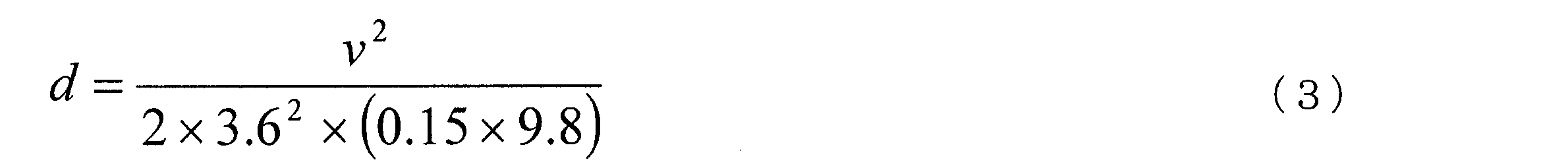
- the vehicle behavior conditions become severe, for example, when the brake depression amount must be suddenly increased or the steering angle of the steering wheel must be suddenly increased. Is the case. For example, when a signal turns red when attempting to pass straight through an intersection, vehicle behavior conditions become severe.
- v [km / h] is the speed when heading for the intersection.
- t be the time from to the stop line at the intersection.
- the place where the action is determined is the place where the brake pedal is started to stop at the stop line.
- the stop position of the own vehicle is the same as the position of the traffic light for easy explanation.
- Equation (1) The distance (d [m]) from the location where the action is determined to the stop line at the intersection is expressed by Equation (1).
- equation (2) holds between the speed (v) and time (t) when heading for the intersection.
- the recognition determination unit 5 determines the presence or absence of an obstacle located around the feature.
- the periphery of the feature is within a range that is a necessary recognition distance away from the position of the feature, and is a range between the own vehicle and the feature.
- the recognition determination unit 5 determines whether there is an obstacle that hides the feature when the vehicle recognizes the feature.
- a sign 201 exists between the traffic light 101 and the own vehicle. In such a case, even if the driving control unit 10 uses the sensor 12 to capture an image of the traveling direction of the host vehicle, the traffic signal 101 is hidden behind the sign 201 and cannot be detected. Therefore, in the example of FIG. 6C, the recognition determination unit 5 determines that there is an obstacle around the feature.
- step S29 the recognition determination unit 5 sets a feature detection range for the position of the vehicle.
- the position of the own vehicle is a position away from the feature to be recognized by a necessary recognition distance.
- a plurality of sensors such as a millimeter wave, a radar, and a laser are provided in the own vehicle so that each sensor complements the detection range.
- the detection distance of the sensor is 200 meters for millimeter waves, several hundred meters for radar, 100 meters for lasers, and several tens of meters for cameras.
- the detection range of the sensor is specified not only by distance but also by angle. In the millimeter wave, the detection range is relatively narrow, but the camera can be selected to narrow or widen the detection range depending on the wide angle of the lens.
- the maximum detection range by those sensors may be the detection range of the sensor, or the minimum detection The range may be the detection range of the sensor.
- FIG. 7A and 7B are diagrams showing the same layout as FIG. 6A.
- 7A is a diagram for explaining a detection range when a narrow-angle lens is used for the sensor 12
- FIG. 7B is a diagram for explaining a detection range when a wide-angle lens is used for the sensor 12.
- FIG. 7A and 7B, X represents a detection range.
- the recognition level calculation unit 6 calculates the recognition level of the feature based on the layout, the necessary recognition distance, the presence or absence of an obstacle, and the detection range of the sensor 12.
- the information shown in the layout includes not only the shape of the road at the intersection where the traffic signal is installed, but also the curvature of the road before the intersection. Information on the curvature of the road is recorded in the database 11 as road information. For example, as shown in FIG. 6A, when the road is curved in front of the intersection, the traffic light can be recognized in front of the vehicle (the direction along the dotted line L in FIG. 6A) from the position of the vehicle shown in FIG. 6A. Can not. In order to recognize the traffic signal directly in front, the host vehicle travels from the position shown in FIG.
- the host vehicle cannot recognize the traffic signal in front of it. Therefore, in order to recognize the traffic light in front, the vehicle must recognize it by approaching the intersection. That is, as shown in FIG. 6A, when the road in front of the intersection has a curve with a certain curvature and the traffic signal 101 is away from the direction directly in front of the host vehicle, the degree of recognition is low. .
- the recognition level calculation unit 6 calculates the recognition level of the traffic signal 103 so as to be higher than the recognition level of the traffic signal 101.
- the layout information is not limited to road curvature, but may include road gradient information.
- road gradient information For example, when the vehicle is heading for an intersection with a traffic light, if the road in front of the intersection is a slope, the vehicle will have a traffic light compared to the case where the road in front of the intersection is flat. It becomes difficult to recognize.
- the recognition level calculation unit 6 calculates the recognition level based on the road gradient. For example, the recognition level calculation unit 6 calculates the recognition level so that the recognition level decreases as the road gradient increases.
- the recognition level calculation unit 6 performs a calculation so that the recognition level is lower when there is an obstacle around the feature to be calculated than when there is no obstacle. For example, when FIG. 6A is compared with FIG. 6C, in the case shown in FIG. 6C, there is a sign 201 that hides the traffic signal 101. Therefore, the recognition level calculation unit 6 calculates the recognition level in the case shown in FIG. 6C to be lower than the recognition level in the case shown in FIG. 6A.
- the obstacle is not limited to the sign 201, and may be a building or a tree, for example. Information on buildings and trees may be recorded in the database 11 as map data.
- the recognition level calculation unit 6 calculates the recognition level of the feature based on the detection range of the sensor 12. Specifically, the recognition level calculation unit 6 makes the recognition level when the feature to be calculated is within the detection range higher than the recognition level when the feature to be calculated is not within the detection range. Calculate to For example, when FIG. 7A is compared with FIG. 7B, in the case shown in FIG. 7B, the traffic light 101 is located within the detection range of the sensor 12. Therefore, the recognition level calculation unit 6 calculates the recognition level in the case shown in FIG. 7B to be higher than the recognition level in the case shown in FIG. 7A.
- step S31 to step S35 is the same as the control flow from step S8 to step S12 of the first embodiment.
- the vehicle curvature or gradient is included before the host vehicle actually approaches the intersection.
- the difficulty in recognizing the traffic light caused by the road layout, the presence or absence of obstacles, and the detection range of the sensor 12 is determined. Therefore, it can be determined whether to pass or avoid the intersection with the traffic signal.
- the driving assistance vehicle and the automatic driving vehicle can easily recognize a feature and calculate a travel route on which the vehicle can travel.
- the vehicle speed of the host vehicle is estimated, and the necessary recognition distance is measured based on the estimated vehicle speed. Accordingly, the necessary recognition distance can be measured under the vehicle speed condition when actually traveling on the travel route.
- the legal speed is estimated as the vehicle speed, and the necessary recognition distance is measured based on the legal speed. Thereby, it is possible to determine the difficulty of recognizing the feature under the most severe speed condition.
- the vehicle speed is estimated when the vehicle has traveled in the past, and the necessary recognition distance is measured based on the estimated speed. This makes it possible to determine the difficulty in recognizing features under typical speed conditions.
- the difficulty of the feature is determined based on the presence or absence of an obstacle located around the feature. Thereby, it is possible to grasp the feature that is difficult to recognize due to the obstacle.
- the difficulty in recognizing the feature is determined based on the curvature of the road or the gradient of the road. This makes it possible to grasp features that are difficult to recognize due to the curvature of the road or the gradient of the road.
- the vehicle speed estimation unit 8 selects one of the vehicle speed and the legal speed when the vehicle has traveled in the past, and estimates the selected speed as the vehicle speed of the host vehicle, according to the scheduled date and time, weather conditions at the time of travel, and the like. May be. Thereby, it is possible to determine the difficulty of recognizing the feature according to the condition affecting the vehicle speed.
- the vehicle speed estimation unit 8 corresponds to the vehicle speed estimation means of the present invention.
- a travel route calculation apparatus according to another embodiment of the invention will be described.
- part of the control of the recognition determination unit 5 is different from the first embodiment described above.
- the configuration of the travel route calculation device is the same as the configuration according to the second embodiment.
- description of 1st Embodiment and 2nd Embodiment is used.
- FIG. 8 is a flowchart showing a control flow of the travel route calculation apparatus.
- step S41 to step S51 is the same as the control flow from step S1 to step S11 of the first embodiment.
- step S52 the vehicle estimation unit 8 calculates acceleration / deceleration when traveling toward the avoidance location set in step S51.
- FIGS. 9A and 9B are diagrams showing layouts of intersections with traffic lights. The position of the own vehicle is different between FIGS. 9A and 9B. The road layout shown in FIGS. 9A and 9B is the same as FIG. 6A.
- the traffic lights 101 and 102 turn red, and if the vehicle tries to decelerate at 0.15G.
- a braking distance of about 95 [m] is required. Therefore, in order to decelerate at 0.15 G from the state where the host vehicle is traveling at 60 [km / h] and stop at the stop line, the host vehicle is braked from the traffic signal 101 (about 95 [m]).
- the traffic light 101 must be recognized at the position of the separated curve.
- the braking distance for the vehicle to stop at the stop line at the intersection is from 95 [m]. It can be shortened to 42 [m].
- the recognition degree calculation unit 6 sets the recognition degree of the traffic lights 101 and 102 to a low value (corresponding to the control flow of step S47 in FIG. 8).
- the recognition degree shown in the example of FIG. 9A is smaller than the threshold value, and the intersection location shown in FIG. 9A is set as an avoidance location.
- the vehicle speed estimation unit 8 calculates the speed at which the vehicle decelerates toward the avoidance point, assuming that the vehicle decelerates while traveling on a curve based on the road layout as shown in FIGS. 9A and 9B. Specifically, the vehicle speed estimation unit 8 estimates that the vehicle speed is decelerated from 60 [km / h] to 40 [km / h].
- the distance measuring unit 4 calculates a necessary recognition distance based on the vehicle speed for each deceleration.
- the necessary recognition distance is a distance from the own vehicle to the feature in a state where the vehicle speed has been reduced to the vehicle speed estimated by the vehicle speed estimation unit 8.
- the feature is installed at a place set as an avoidance point.
- the distance measurement part 4 is calculating the required recognition distance based on the behavior of the own vehicle.
- the behavior of the host vehicle is that the host vehicle decelerates at a curve before the intersection in the example of FIG. 9B.
- the recognition degree calculation part 6 calculates a recognition degree again based on the required recognition distance and layout after deceleration.
- the recognition degree of FIG. 9A is a low value.
- the vehicle recognizes the traffic lights 101 and 102 that must be recognized. Can be recognized, so the degree of recognition increases.
- step S54 the recognition determination unit 5 compares the recognition degree calculated again and the threshold value. If the recognition level is greater than or equal to the threshold value, the recognition determination unit 5 determines that the avoidance location setting can be canceled, and the process proceeds to step S55. In step 55, the avoidance location setting unit 7 cancels the avoidance location setting. On the other hand, when the recognition level is lower than the threshold, the recognition determination unit 5 determines that the avoidance location setting cannot be canceled, and the avoidance location setting unit 7 does not cancel the avoidance location setting.
- step S56 the travel route calculation unit 2 calculates the travel route from the current location of the vehicle to the target point after avoiding the avoidance point. Then, the control flow shown in FIG. 8 ends.
- the vehicle when there is an intersection with a signal that must pass through on the route planned for traveling of the vehicle, the vehicle is accelerated and decelerated before the vehicle reaches the intersection. It can be calculated so as to be an intersection that can pass through the intersection. As a result, a travel route with few avoidance points can be calculated.
- the deceleration of the vehicle is not limited to the curve before the intersection, and it is necessary to temporarily decelerate or stop even when making a right turn or a left turn at the intersection, for example. Therefore, by recalculating the recognition degree of the feature based on the behavior of the own vehicle, the place where the feature is installed can be excluded from the avoidance place. As a result, in automatic operation control, it is possible to pass through such an intersection while turning right, left, or decelerating.
- the necessary recognition distance is calculated based on the behavior of the host vehicle.
- the required recognition distance is calculated in consideration of typical vehicle behavior (acceleration / deceleration, traveling at a constant speed, etc.), so action determination is performed under conditions that more closely match the actual driving scene. It is possible to calculate the distance required when
- the difficulty in recognizing the feature is determined based on the acceleration or deceleration of the vehicle.
- the degree of recognition that changes due to acceleration / deceleration is calculated, and it is determined whether or not to set as an avoidance location. Therefore, acceleration and deceleration are performed even in a location that is set as an avoidance location in normal traveling. If possible, it can be excluded from the avoidance points. And the place excluded from the avoidance location can be included in the travel route.
Abstract
Description
《第1実施形態》
図4は、発明の他の実施形態に係る走行経路演算装置のブロック図である。本例では上述した第1実施形態に対して、車速推定部8を有する点と、距離測定部4及び認識判断部5の制御の一部が異なる。これ以外の構成は上述した第1実施形態と同じであり、その記載を援用する。


発明の他の実施形態に係る走行経路演算装置を説明する。本例では上述した第1実施形態に対して、認識判断部5の制御の一部が異なる。走行経路演算装置の構成は、第2実施形態に係る構成と同様である。第3実施形態において、第1実施形態及び第2実施形態の記載を援用する。
2…走行経路演算部
3…情報取得部
4…距離測定部
5…認識判断部
6…認識度演算部
7…回避箇所設定部
8…車速推定部
Claims (15)
- 自車が目的地に到着するまでの走行経路を演算する走行経路演算手段と、
前記自車による地物の認識に影響する対象物の情報を対象物情報として取得する情報取得手段と、
前記自車の行動決定の際に前記自車が前記地物の認識のために必要とする、前記自車から前記地物までの距離を必要認識距離として測定する距離測定手段と、
前記対象物情報及び前記必要認識距離に基づき、前記地物の認識の困難性を判断する判断手段とを備え、
前記走行経路演算手段は、前記判断手段により前記地物の認識が困難であると判断された箇所を回避した上で前記走行経路を演算する
ことを特徴とする走行経路演算装置。 - 請求項1記載の走行経路演算装置において、
前記情報取得手段は、前記対象物情報に含まれる道路形状の情報、及び、前記対象物情報に含まれる前記地物の位置情報を取得し、
前記判断手段は、
前記道路形状の情報及び前記地物の位置情報に基づいて道路のレイアウト上における前記地物の位置を特定し、前記位置及び前記必要認識情報に基づき前記地物の認識の困難性を判断する
ことを特徴とする走行経路演算装置。 - 請求項1又は2記載の走行経路演算装置において、
前記判断手段は、
前記対象物情報及び前記必要認識距離に基づき、前記地物の認識しやすさの指標を認識度として演算し、
前記認識度が所定の閾値より低い場合に前記地物の認識が困難であると判断する
ことを特徴とする走行経路演算装置。 - 請求項1~3のいずれか一項に記載の走行経路演算装置において、
前記自車の車速を推定する車速推定手段を備え、
前記距離測定手段は、前記車速に基づいて前記必要認識距離を測定する
ことを特徴とする走行経路演算装置。 - 請求項4記載の走行経路演算装置において、
前記車速推定手段は、前記走行経路の法定速度を前記車速として推定する
ことを特徴とする走行経路演算装置。 - 請求項4記載の走行経路演算装置において、
前記車速推定手段は、前記走行経路上の所定の道路を過去に走行したときの前記車速に基づき、前記所定の道路を走行する際の前記車速を推定する
ことを特徴とする走行経路演算装置。 - 請求項1~6のいずれか一項に記載の走行経路演算装置において、
前記情報取得手段は、前記対象物情報に含まれる道路形状の情報、及び、前記対象物情報に含まれる前記地物の情報を取得し、
前記判断手段は、前記自車の挙動が変化する原因となる前記道路形状をもつ地点又は前記自車の挙動が変化する原因となる前記地物をもつ地点を特定し、前記地点における前記困難性を判断する
ことを特徴とする走行経路演算装置。 - 請求項7記載の走行経路演算装置において、
前記判断手段は、前記自車の挙動と他車の挙動が干渉する地点を、前記困難性を判断するための前記地点として特定する
ことを特徴とする走行経路演算装置。 - 請求項7に記載の走行経路演算装置において、
前記判断手段は、交通ルールを表示した前記地物をもつ地点を、前記困難性を判断するための前記地点として特定する
ことを特徴とする走行経路演算装置。 - 請求項1~9のいずれか一項に記載の走行経路演算装置において、
前記距離測定手段は、前記自車の挙動に基づいて前記必要認識距離を測定する
ことを特徴とする走行経路演算装置。 - 請求項1~10のいずれか一項に記載の走行経路演算装置において、
前記判断手段は、前記地物の周辺に位置する障害物に基づき前記地物の認識の困難性を判断する
ことを特徴とする走行経路演算装置。 - 請求項1~11のいずれか一項に記載の走行経路演算装置において、
前記情報取得手段は、前記対象物情報に含まれる道路形状の情報を取得し、
前記判断手段は、前記道路形状の情報により示される道路の曲率又は道路の勾配に基づき前記地物の認識の困難性を判断する
ことを特徴とする走行経路演算装置。 - 請求項1~12のいずれか一項に記載の走行経路演算装置において、
前記地物を検出する地物検出手段をさらに備え、
前記判断手段は、前記地物検出手段の検出範囲に基づいて前記地物の認識の困難性を判断する
ことを特徴とする走行経路演算装置。 - 請求項1~13のいずれか一項に記載の走行経路装置において、
前記判断手段は、前記地物に向かう前記自車の加速又は減速に基づいて前記地物の認識の困難性を判断する
ことを特徴とする走行経路演算装置。 - 自車が目的地に到着するまでの走行経路を演算する走行経路演算手段と、
前記自車による地物の認識に影響する対象物の情報を対象物情報として取得する情報取得手段と、
前記自車の行動決定の際に前記自車が前記地物の認識のために必要とする、前記自車から前記地物までの距離を必要認識距離として測定する距離測定手段と、
前記対象物情報及び前記必要認識距離に基づき、前記地物の認識しやすさの指標を認識度として演算する認識度演算手段とを備え、
前記認識度演算手段は、
前記走行経路上の前記地物の各箇所で、複数の前記走行経路毎に前記認識度を演算し、
前記走行経路演算手段は、
前記複数の走行経路のうち、前記認識度の総和が最も高い走行経路、又は、所定値よりも高い前記認識度の数が最も多い走行経路を、前記自車の走行する前記走行経路として演算する
ことを特徴とする走行経路演算装置。
Priority Applications (8)
| Application Number | Priority Date | Filing Date | Title |
|---|---|---|---|
| JP2016555009A JP6399100B2 (ja) | 2014-10-22 | 2014-10-22 | 走行経路演算装置 |
| RU2017116737A RU2661963C1 (ru) | 2014-10-22 | 2014-10-22 | Устройство вычисления маршрута движения |
| US15/520,334 US10359293B2 (en) | 2014-10-22 | 2014-10-22 | Travel route calculation device |
| MX2017005116A MX359042B (es) | 2014-10-22 | 2014-10-22 | Dispositivo de cálculo de la ruta de desplazamiento. |
| EP14904401.8A EP3211374B1 (en) | 2014-10-22 | 2014-10-22 | Travel route calculation device |
| CN201480082849.6A CN107076564B (zh) | 2014-10-22 | 2014-10-22 | 行驶路径运算装置 |
| BR112017008376-0A BR112017008376B1 (pt) | 2014-10-22 | 2014-10-22 | Dispositivo de cálculo de rota de deslocamento |
| PCT/JP2014/078125 WO2016063385A1 (ja) | 2014-10-22 | 2014-10-22 | 走行経路演算装置 |
Applications Claiming Priority (1)
| Application Number | Priority Date | Filing Date | Title |
|---|---|---|---|
| PCT/JP2014/078125 WO2016063385A1 (ja) | 2014-10-22 | 2014-10-22 | 走行経路演算装置 |
Publications (1)
| Publication Number | Publication Date |
|---|---|
| WO2016063385A1 true WO2016063385A1 (ja) | 2016-04-28 |
Family
ID=55760454
Family Applications (1)
| Application Number | Title | Priority Date | Filing Date |
|---|---|---|---|
| PCT/JP2014/078125 WO2016063385A1 (ja) | 2014-10-22 | 2014-10-22 | 走行経路演算装置 |
Country Status (8)
| Country | Link |
|---|---|
| US (1) | US10359293B2 (ja) |
| EP (1) | EP3211374B1 (ja) |
| JP (1) | JP6399100B2 (ja) |
| CN (1) | CN107076564B (ja) |
| BR (1) | BR112017008376B1 (ja) |
| MX (1) | MX359042B (ja) |
| RU (1) | RU2661963C1 (ja) |
| WO (1) | WO2016063385A1 (ja) |
Cited By (6)
| Publication number | Priority date | Publication date | Assignee | Title |
|---|---|---|---|---|
| EP3388789A1 (en) | 2017-04-13 | 2018-10-17 | Panasonic Intellectual Property Corporation of America | Information processing method and information processing apparatus |
| JP2019121307A (ja) * | 2018-01-11 | 2019-07-22 | トヨタ自動車株式会社 | 信号機認識装置、及び自動運転システム |
| WO2019146052A1 (ja) * | 2018-01-25 | 2019-08-01 | 日産自動車株式会社 | 自動運転車両の制御方法および制御装置 |
| JP2020109560A (ja) * | 2019-01-04 | 2020-07-16 | 日産自動車株式会社 | 信号機認識方法及び信号機認識装置 |
| JP2020109559A (ja) * | 2019-01-04 | 2020-07-16 | 日産自動車株式会社 | 信号機認識方法及び信号機認識装置 |
| US11409281B2 (en) | 2017-05-31 | 2022-08-09 | Panasonic Intellectual Property Corporation Of America | Information processing method for determining difficult area in which travel of vehicle by automatic driving is difficult, information processing apparatus, system, and storage medium |
Families Citing this family (6)
| Publication number | Priority date | Publication date | Assignee | Title |
|---|---|---|---|---|
| US9958864B2 (en) * | 2015-11-04 | 2018-05-01 | Zoox, Inc. | Coordination of dispatching and maintaining fleet of autonomous vehicles |
| US10479333B2 (en) * | 2017-11-20 | 2019-11-19 | Ford Global Technologies, Llc | Method and apparatus for navigation accommodating train crossings |
| JP2020111300A (ja) * | 2019-01-17 | 2020-07-27 | マツダ株式会社 | 車両運転支援システム及び方法 |
| JP7281289B2 (ja) * | 2019-01-30 | 2023-05-25 | フォルシアクラリオン・エレクトロニクス株式会社 | 演算装置 |
| US11210951B2 (en) * | 2020-03-03 | 2021-12-28 | Verizon Patent And Licensing Inc. | System and method for location data fusion and filtering |
| CN111637898B (zh) * | 2020-06-02 | 2022-07-01 | 安徽宇呈数据技术有限公司 | 一种高精度导航电子地图的处理方法和装置 |
Citations (3)
| Publication number | Priority date | Publication date | Assignee | Title |
|---|---|---|---|---|
| JP2008157820A (ja) * | 2006-12-25 | 2008-07-10 | Fujitsu Ten Ltd | 標識情報提供装置 |
| JP2012247315A (ja) * | 2011-05-27 | 2012-12-13 | Zenrin Co Ltd | 経路案内装置 |
| JP2013083498A (ja) * | 2011-10-07 | 2013-05-09 | Mic Ware:Kk | ナビゲーション装置、ナビゲーション方法、およびプログラム |
Family Cites Families (11)
| Publication number | Priority date | Publication date | Assignee | Title |
|---|---|---|---|---|
| JP4724043B2 (ja) * | 2006-05-17 | 2011-07-13 | トヨタ自動車株式会社 | 対象物認識装置 |
| JP4680131B2 (ja) * | 2006-05-29 | 2011-05-11 | トヨタ自動車株式会社 | 自車位置測定装置 |
| RU2395122C2 (ru) * | 2006-11-15 | 2010-07-20 | Федеральное государственное образовательное учреждение высшего профессионального образования Мурманский государственный технический университет | Способ управления движением подвижных объектов |
| JP4984152B2 (ja) * | 2007-08-31 | 2012-07-25 | アイシン・エィ・ダブリュ株式会社 | 画像認識システム、サーバ装置、及び画像認識装置 |
| JP2009257991A (ja) * | 2008-04-18 | 2009-11-05 | Denso Corp | カーナビゲーションシステム |
| JP5233606B2 (ja) * | 2008-11-19 | 2013-07-10 | 富士通株式会社 | 絶対移動経路算出装置及び方法、並びにプログラム |
| US20110190972A1 (en) * | 2010-02-02 | 2011-08-04 | Gm Global Technology Operations, Inc. | Grid unlock |
| JP5429380B2 (ja) * | 2010-07-27 | 2014-02-26 | トヨタ自動車株式会社 | 運転支援装置 |
| US8640594B2 (en) * | 2011-02-01 | 2014-02-04 | Corvid Technologies, Inc. | Blast deflecting shield for ground vehicles and shielded ground vehicles and methods including same |
| JP5729480B2 (ja) | 2011-10-03 | 2015-06-03 | トヨタ自動車株式会社 | 車両の運転支援システム |
| RU128747U1 (ru) * | 2012-12-25 | 2013-05-27 | Открытое Акционерное Общество "Российские Железные Дороги" | Устройство для сбора данных путевых объектов и установленных скоростей движения для систем автоведения и безопасности |
-
2014
- 2014-10-22 WO PCT/JP2014/078125 patent/WO2016063385A1/ja active Application Filing
- 2014-10-22 EP EP14904401.8A patent/EP3211374B1/en active Active
- 2014-10-22 RU RU2017116737A patent/RU2661963C1/ru active
- 2014-10-22 BR BR112017008376-0A patent/BR112017008376B1/pt active IP Right Grant
- 2014-10-22 CN CN201480082849.6A patent/CN107076564B/zh active Active
- 2014-10-22 JP JP2016555009A patent/JP6399100B2/ja active Active
- 2014-10-22 MX MX2017005116A patent/MX359042B/es active IP Right Grant
- 2014-10-22 US US15/520,334 patent/US10359293B2/en active Active
Patent Citations (3)
| Publication number | Priority date | Publication date | Assignee | Title |
|---|---|---|---|---|
| JP2008157820A (ja) * | 2006-12-25 | 2008-07-10 | Fujitsu Ten Ltd | 標識情報提供装置 |
| JP2012247315A (ja) * | 2011-05-27 | 2012-12-13 | Zenrin Co Ltd | 経路案内装置 |
| JP2013083498A (ja) * | 2011-10-07 | 2013-05-09 | Mic Ware:Kk | ナビゲーション装置、ナビゲーション方法、およびプログラム |
Non-Patent Citations (1)
| Title |
|---|
| See also references of EP3211374A4 * |
Cited By (12)
| Publication number | Priority date | Publication date | Assignee | Title |
|---|---|---|---|---|
| EP3388789A1 (en) | 2017-04-13 | 2018-10-17 | Panasonic Intellectual Property Corporation of America | Information processing method and information processing apparatus |
| US10838422B2 (en) | 2017-04-13 | 2020-11-17 | Panasonic Intellectual Property Corporation Of America | Information processing method and information processing apparatus |
| US11409281B2 (en) | 2017-05-31 | 2022-08-09 | Panasonic Intellectual Property Corporation Of America | Information processing method for determining difficult area in which travel of vehicle by automatic driving is difficult, information processing apparatus, system, and storage medium |
| JP2019121307A (ja) * | 2018-01-11 | 2019-07-22 | トヨタ自動車株式会社 | 信号機認識装置、及び自動運転システム |
| JP7067067B2 (ja) | 2018-01-11 | 2022-05-16 | トヨタ自動車株式会社 | 信号機認識装置、及び自動運転システム |
| WO2019146052A1 (ja) * | 2018-01-25 | 2019-08-01 | 日産自動車株式会社 | 自動運転車両の制御方法および制御装置 |
| US20200361488A1 (en) * | 2018-01-25 | 2020-11-19 | Nissan Motor Co., Ltd. | Control method and control device for controlling autonomously driven vehicle |
| US11648960B2 (en) | 2018-01-25 | 2023-05-16 | Nissan Motor Co., Ltd. | Control method and control device for controlling autonomously driven vehicle |
| JP2020109560A (ja) * | 2019-01-04 | 2020-07-16 | 日産自動車株式会社 | 信号機認識方法及び信号機認識装置 |
| JP2020109559A (ja) * | 2019-01-04 | 2020-07-16 | 日産自動車株式会社 | 信号機認識方法及び信号機認識装置 |
| JP7245653B2 (ja) | 2019-01-04 | 2023-03-24 | 日産自動車株式会社 | 信号機認識方法及び信号機認識装置 |
| JP7261588B2 (ja) | 2019-01-04 | 2023-04-20 | 日産自動車株式会社 | 信号機認識方法及び信号機認識装置 |
Also Published As
| Publication number | Publication date |
|---|---|
| BR112017008376B1 (pt) | 2022-04-05 |
| MX2017005116A (es) | 2017-07-14 |
| US20170314943A1 (en) | 2017-11-02 |
| MX359042B (es) | 2018-09-13 |
| RU2661963C1 (ru) | 2018-07-23 |
| BR112017008376A2 (pt) | 2017-12-19 |
| EP3211374B1 (en) | 2020-12-16 |
| EP3211374A4 (en) | 2018-01-24 |
| CN107076564A (zh) | 2017-08-18 |
| JPWO2016063385A1 (ja) | 2017-08-03 |
| US10359293B2 (en) | 2019-07-23 |
| JP6399100B2 (ja) | 2018-10-03 |
| CN107076564B (zh) | 2018-11-13 |
| EP3211374A1 (en) | 2017-08-30 |
Similar Documents
| Publication | Publication Date | Title |
|---|---|---|
| JP6399100B2 (ja) | 走行経路演算装置 | |
| US10703362B2 (en) | Autonomous driving autonomous system, automated driving assistance method, and computer program | |
| US10832571B2 (en) | Safety driving assistant system, server, vehicle and program | |
| CN107430807B (zh) | 自动驾驶辅助系统、自动驾驶辅助方法以及计算机程序 | |
| CN111027420B (zh) | 用于模仿前车的系统和方法 | |
| JP6323565B2 (ja) | 運転支援装置 | |
| US10239539B2 (en) | Vehicle travel control method and vehicle travel control device | |
| US8134480B2 (en) | Image processing system and method | |
| US8005615B2 (en) | Navigation system | |
| US10510249B2 (en) | Safety driving assistant system, vehicle, and program | |
| JP6304393B2 (ja) | 走行経路演算装置 | |
| KR20190014871A (ko) | 차량의 후방에 위치한 응급 차량에 기초하여 상기 차량의 주행 경로를 변경하는 장치 및 방법 | |
| JP4859760B2 (ja) | カーナビゲーション装置、道路標識認識方法およびプログラム | |
| US20180144201A1 (en) | Scene Understanding Device | |
| WO2020066505A1 (ja) | 認識装置 | |
| US20130096822A1 (en) | Navigation device | |
| CN109425861B (zh) | 本车位置可信度运算装置 | |
| JP7043765B2 (ja) | 車両走行制御方法及び装置 | |
| JP6232883B2 (ja) | 自車位置認識装置 | |
| WO2019127076A1 (en) | Automated driving vehicle control by collision risk map | |
| JP7395837B2 (ja) | ナビゲーション装置、ナビゲーション方法、およびプログラム | |
| JP2021101268A (ja) | 自動運転車 | |
| US20230150534A1 (en) | Vehicle control system and vehicle driving method using the vehicle control system | |
| JP2023151311A (ja) | 走行制御方法及び走行制御装置 |
Legal Events
| Date | Code | Title | Description |
|---|---|---|---|
| 121 | Ep: the epo has been informed by wipo that ep was designated in this application |
Ref document number: 14904401 Country of ref document: EP Kind code of ref document: A1 |
|
| ENP | Entry into the national phase |
Ref document number: 2016555009 Country of ref document: JP Kind code of ref document: A |
|
| WWE | Wipo information: entry into national phase |
Ref document number: 15520334 Country of ref document: US |
|
| WWE | Wipo information: entry into national phase |
Ref document number: MX/A/2017/005116 Country of ref document: MX |
|
| NENP | Non-entry into the national phase |
Ref country code: DE |
|
| REEP | Request for entry into the european phase |
Ref document number: 2014904401 Country of ref document: EP |
|
| ENP | Entry into the national phase |
Ref document number: 2017116737 Country of ref document: RU Kind code of ref document: A |
|
| REG | Reference to national code |
Ref country code: BR Ref legal event code: B01A Ref document number: 112017008376 Country of ref document: BR |
|
| ENP | Entry into the national phase |
Ref document number: 112017008376 Country of ref document: BR Kind code of ref document: A2 Effective date: 20170424 |