WO2016063384A1 - 走行経路演算装置 - Google Patents
走行経路演算装置 Download PDFInfo
- Publication number
- WO2016063384A1 WO2016063384A1 PCT/JP2014/078124 JP2014078124W WO2016063384A1 WO 2016063384 A1 WO2016063384 A1 WO 2016063384A1 JP 2014078124 W JP2014078124 W JP 2014078124W WO 2016063384 A1 WO2016063384 A1 WO 2016063384A1
- Authority
- WO
- WIPO (PCT)
- Prior art keywords
- travel route
- vehicle
- feature
- route calculation
- calculation device
- Prior art date
Links
- 238000004364 calculation method Methods 0.000 title claims abstract description 67
- 238000001514 detection method Methods 0.000 claims abstract description 71
- 238000005259 measurement Methods 0.000 abstract description 6
- 230000003542 behavioural effect Effects 0.000 abstract 1
- 230000009471 action Effects 0.000 description 21
- 238000010586 diagram Methods 0.000 description 13
- 230000007423 decrease Effects 0.000 description 8
- 230000008859 change Effects 0.000 description 4
- 238000000034 method Methods 0.000 description 4
- 238000013459 approach Methods 0.000 description 3
- 238000012545 processing Methods 0.000 description 3
- 230000006870 function Effects 0.000 description 2
- 239000011159 matrix material Substances 0.000 description 2
- 230000004048 modification Effects 0.000 description 2
- 238000012986 modification Methods 0.000 description 2
- 230000000295 complement effect Effects 0.000 description 1
- 230000003247 decreasing effect Effects 0.000 description 1
- 238000003384 imaging method Methods 0.000 description 1
- 230000009467 reduction Effects 0.000 description 1
Images


Classifications
-
- B—PERFORMING OPERATIONS; TRANSPORTING
- B60—VEHICLES IN GENERAL
- B60W—CONJOINT CONTROL OF VEHICLE SUB-UNITS OF DIFFERENT TYPE OR DIFFERENT FUNCTION; CONTROL SYSTEMS SPECIALLY ADAPTED FOR HYBRID VEHICLES; ROAD VEHICLE DRIVE CONTROL SYSTEMS FOR PURPOSES NOT RELATED TO THE CONTROL OF A PARTICULAR SUB-UNIT
- B60W30/00—Purposes of road vehicle drive control systems not related to the control of a particular sub-unit, e.g. of systems using conjoint control of vehicle sub-units, or advanced driver assistance systems for ensuring comfort, stability and safety or drive control systems for propelling or retarding the vehicle
- B60W30/18—Propelling the vehicle
- B60W30/18009—Propelling the vehicle related to particular drive situations
- B60W30/18154—Approaching an intersection
-
- B—PERFORMING OPERATIONS; TRANSPORTING
- B60—VEHICLES IN GENERAL
- B60W—CONJOINT CONTROL OF VEHICLE SUB-UNITS OF DIFFERENT TYPE OR DIFFERENT FUNCTION; CONTROL SYSTEMS SPECIALLY ADAPTED FOR HYBRID VEHICLES; ROAD VEHICLE DRIVE CONTROL SYSTEMS FOR PURPOSES NOT RELATED TO THE CONTROL OF A PARTICULAR SUB-UNIT
- B60W60/00—Drive control systems specially adapted for autonomous road vehicles
- B60W60/001—Planning or execution of driving tasks
-
- G—PHYSICS
- G01—MEASURING; TESTING
- G01C—MEASURING DISTANCES, LEVELS OR BEARINGS; SURVEYING; NAVIGATION; GYROSCOPIC INSTRUMENTS; PHOTOGRAMMETRY OR VIDEOGRAMMETRY
- G01C21/00—Navigation; Navigational instruments not provided for in groups G01C1/00 - G01C19/00
- G01C21/26—Navigation; Navigational instruments not provided for in groups G01C1/00 - G01C19/00 specially adapted for navigation in a road network
- G01C21/34—Route searching; Route guidance
- G01C21/3453—Special cost functions, i.e. other than distance or default speed limit of road segments
- G01C21/3461—Preferred or disfavoured areas, e.g. dangerous zones, toll or emission zones, intersections, manoeuvre types, segments such as motorways, toll roads, ferries
-
- G—PHYSICS
- G05—CONTROLLING; REGULATING
- G05D—SYSTEMS FOR CONTROLLING OR REGULATING NON-ELECTRIC VARIABLES
- G05D1/00—Control of position, course or altitude of land, water, air, or space vehicles, e.g. automatic pilot
- G05D1/02—Control of position or course in two dimensions
- G05D1/021—Control of position or course in two dimensions specially adapted to land vehicles
- G05D1/0268—Control of position or course in two dimensions specially adapted to land vehicles using internal positioning means
- G05D1/0274—Control of position or course in two dimensions specially adapted to land vehicles using internal positioning means using mapping information stored in a memory device
-
- B—PERFORMING OPERATIONS; TRANSPORTING
- B60—VEHICLES IN GENERAL
- B60W—CONJOINT CONTROL OF VEHICLE SUB-UNITS OF DIFFERENT TYPE OR DIFFERENT FUNCTION; CONTROL SYSTEMS SPECIALLY ADAPTED FOR HYBRID VEHICLES; ROAD VEHICLE DRIVE CONTROL SYSTEMS FOR PURPOSES NOT RELATED TO THE CONTROL OF A PARTICULAR SUB-UNIT
- B60W2520/00—Input parameters relating to overall vehicle dynamics
- B60W2520/10—Longitudinal speed
-
- B—PERFORMING OPERATIONS; TRANSPORTING
- B60—VEHICLES IN GENERAL
- B60W—CONJOINT CONTROL OF VEHICLE SUB-UNITS OF DIFFERENT TYPE OR DIFFERENT FUNCTION; CONTROL SYSTEMS SPECIALLY ADAPTED FOR HYBRID VEHICLES; ROAD VEHICLE DRIVE CONTROL SYSTEMS FOR PURPOSES NOT RELATED TO THE CONTROL OF A PARTICULAR SUB-UNIT
- B60W2554/00—Input parameters relating to objects
- B60W2554/80—Spatial relation or speed relative to objects
- B60W2554/802—Longitudinal distance
-
- B—PERFORMING OPERATIONS; TRANSPORTING
- B60—VEHICLES IN GENERAL
- B60W—CONJOINT CONTROL OF VEHICLE SUB-UNITS OF DIFFERENT TYPE OR DIFFERENT FUNCTION; CONTROL SYSTEMS SPECIALLY ADAPTED FOR HYBRID VEHICLES; ROAD VEHICLE DRIVE CONTROL SYSTEMS FOR PURPOSES NOT RELATED TO THE CONTROL OF A PARTICULAR SUB-UNIT
- B60W2555/00—Input parameters relating to exterior conditions, not covered by groups B60W2552/00, B60W2554/00
- B60W2555/60—Traffic rules, e.g. speed limits or right of way
Definitions
- the present invention relates to a travel route computing device that computes a travel route.
- Patent Document 1 prepares a risk value matrix that gives a risk score at which an intersection becomes an isolated intersection for each factor feature such as a crossing existing in the exit direction of the intersection and a lane-decreasing portion of the road.
- the route guidance device refers to the risk value matrix for each intersection on the route with respect to the route search result from the departure point to the destination, obtains a danger value score, and an intersection where the danger value score exceeds a predetermined threshold value Are extracted as isolated intersections.
- the route guidance device searches for and guides a route that avoids an isolated intersection.
- a driving assistance vehicle or an autonomous driving vehicle travels after recognizing a traffic light or the like, making an action decision for determining the action of the vehicle.
- a vehicle that performs such action determination in order to travel appropriately, it is necessary to collect information necessary for action determination.
- the problem to be solved by the present invention is to provide a travel route computing device capable of computing a travel route for easily recognizing features necessary for behavior determination for a vehicle traveling by behavior determination.
- the present invention measures the necessary recognition distance necessary for the vehicle to recognize the feature when determining the behavior of the vehicle, and recognizes the feature based on the detection range and the necessary recognition distance of the feature detection means.
- the above problem is solved by calculating the travel route after determining the difficulty of the vehicle and avoiding the location where it is determined that the feature is difficult to recognize.
- the travel route in which the vehicle can easily recognize the feature can be calculated.
- FIG. 1 is a block diagram of a travel route calculation apparatus according to this embodiment.
- FIG. 2 is a diagram showing an example of a road layout.
- FIG. 3 is a flowchart showing a control flow of the travel route calculation apparatus.
- FIG. 4A is a diagram illustrating an example of a road layout.
- FIG. 4B is a diagram illustrating an example of a road layout.
- FIG. 5 is a block diagram of a travel route calculation apparatus according to another embodiment of the present invention.
- FIG. 6 is a flowchart showing a control flow of the travel route calculation apparatus.
- FIG. 7A is a diagram illustrating an example of a road layout.
- FIG. 7B is a diagram illustrating an example of a road layout.
- FIG. 1 is a block diagram of a travel route calculation apparatus according to an embodiment of the present invention.
- the travel route calculation device according to the present embodiment is a device that is mounted on a vehicle and calculates travel accounting when the vehicle is automatically driven.
- the travel route computing device functions as a ROM (Read Only Memory) in which various programs are stored, a CPU (Central Processing Unit) as an operation circuit for executing the programs stored in the ROM, and an accessible storage device.
- ROM Read Only Memory
- CPU Central Processing Unit
- RAM Random Access Memory
- the travel route calculation device includes an operation control unit 10, a database 11, and a sensor 12.
- the database 11 records map data, feature information, road information, and the like.
- the map data includes link data and node data.
- the feature information is, for example, traffic signal information, crossing information, traffic sign information, and the like.
- the road information includes intersection information, road merging information, road shape information of road diversion.
- the sensor 12 is a sensor for detecting the surroundings of the own vehicle, and is a camera, a millimeter wave, a radar, or the like.
- the operation control unit 10 controls the automatic driving of the own vehicle based on the detection value of the sensor 12.
- the driving control unit 10 uses the sensor 12 to recognize a feature necessary for determining the behavior of the own vehicle. Action determination in automatic driving is performed by the vehicle recognizing features such as traffic signals, traffic signs, and railroad crossings.
- the driving control unit 10 specifies a target point when performing the action of the own vehicle based on the feature. For example, when the vehicle makes a right turn as an action decision, the location of the intersection that makes a right turn becomes the target point. Then, the operation control unit 10 performs the determined action at the target point. Thereby, the own vehicle travels in an automatic operation.
- the feature is a traffic signal provided at the intersection, and the behavior of the vehicle according to the display of the traffic signal is defined as the behavior of the vehicle.
- the behavior of the host vehicle is to stop the vehicle at the stop line at the intersection.
- the traffic light is blue
- the behavior of the own vehicle is an operation of passing through the intersection at a predetermined speed. That is, traffic lights and intersections are features that cause the behavior of the vehicle to change.
- the driving control unit 10 sets a target point at which an action is determined as an intersection.
- the driving control unit 10 recognizes a traffic light from a place away from the intersection by a predetermined distance before the vehicle enters the intersection.
- the traffic light is detected by the sensor 12.
- running control part 10 approaches an intersection, it recognizes a traffic signal and determines the action according to the color which a traffic signal displays. Then, the driving control unit 10 causes the vehicle to travel according to the determined action. As a result, automatic driving of the vehicle is performed.
- the operation control unit 10 repeatedly performs the automatic operation control as described above while traveling on the travel route. Note that the above automatic driving control is merely an example, and another control method may be used.
- the travel route calculation device includes a vehicle information detection unit 1, a travel route calculation unit 2, and an information acquisition unit as functional blocks for calculating a travel route suitable for automatic driving when performing automatic driving of the vehicle as described above. 3, a distance measurement unit 4, a vehicle speed estimation unit 5, and a recognition determination unit 6.
- the recognition determination unit 6 includes an avoidance location setting unit 7.
- Vehicle information detection unit 1 detects vehicle information of the own vehicle.
- the vehicle information includes position information of the own vehicle.
- the vehicle information detection unit 1 has a function such as GPS.
- the travel route calculation unit 2 acquires vehicle information from the vehicle information detection unit 1 and calculates a travel route from the current location of the vehicle to the destination while referring to the map data.
- the destination is input by the user, for example, and the map data is recorded in the database 11.
- the travel route calculation unit 2 calculates the travel route based on the vehicle information.
- the travel route calculation unit 2 calculates the travel route so as to avoid the avoidance location.
- the information acquisition unit 3 acquires a travel route from the travel route calculation unit 2.
- the information acquisition unit 3 acquires feature information on the travel route.
- Features are things that the vehicle must recognize when deciding the behavior of the vehicle.
- the feature displays a traffic rule that the driver should follow when the vehicle is driven.
- Features include traffic lights on traffic routes, traffic signs, railroad crossings, and the like.
- the information acquisition unit 3 acquires road information from the travel route calculation unit 2.
- the road information includes not only road information on the travel route but also information on roads connected to the road on the travel route. For example, when there is a traffic light on the travel route, not only the road on which the vehicle is scheduled to travel, but also the intersection where the traffic signal is installed and the road information connected to the intersection are included.
- the distance measuring unit 4 measures the necessary recognition distance.
- the necessary recognition distance is a distance that the vehicle needs to recognize the feature when determining the behavior of the vehicle, and is a distance from the position of the recognized feature to the vehicle.
- the vehicle speed estimation unit 5 estimates the vehicle speed of the host vehicle when heading for a feature on the travel route.
- the recognition determination unit 6 determines the difficulty in recognizing the feature based on the detection range of the sensor 12 and the required recognition distance measured by the distance measurement unit 4.
- the feature for which the difficulty is judged is a feature that the vehicle must recognize when performing automatic driving by the driving control unit 10.
- the avoidance location setting unit 7 sets a location where the recognition determination unit 6 determines that it is difficult to recognize the feature as an avoidance location.
- the travel route calculation unit 2 calculates the travel route to the target location while avoiding the avoidance location.
- the driving control unit 10 controls driving of the vehicle based on the travel route calculated avoiding the avoidance points.
- FIG. 2 is a diagram showing a layout of intersections.
- the own vehicle when the own vehicle travels at an intersection by automatic driving, the own vehicle needs to make an action decision according to the display of the traffic light 101.
- the traffic light 101 When the traffic light 101 is displayed in red, the vehicle must stop by the stop line at the intersection. And in order for the own vehicle to make such an action decision, the own vehicle must recognize the traffic light 101 using the sensor 12.
- the vehicle braking distance is determined by the vehicle speed. For example, when the vehicle is running at a high speed, the braking distance becomes long. In such a state, in order to stop the vehicle at the stop line by the red display of the traffic signal 101, the vehicle must recognize the traffic signal 101 at a position at least a braking distance away from the position of the traffic signal 101. .
- the detection range of the sensor 12 is determined in advance by the performance of the sensor 12 and the like. Therefore, when the position of the vehicle is at least a braking distance away from the position of the traffic light 101 and the traffic light 101 is outside the detection range of the sensor 12, it becomes difficult to recognize the traffic light 101.
- the operation control unit 10 cannot recognize the feature necessary for the automatic driving by the sensor 12, and the automatic driving is not normally performed. there is a possibility.
- the travel route calculation device determines the recognizability of the feature on the travel route, and sets the avoidance location on the travel route where the feature is difficult to recognize. Then, a travel route suitable for automatic driving is calculated by calculating the travel route so as to avoid the avoidance point.
- FIG. 3 is a flowchart showing a control flow of the travel route calculation apparatus.
- the flowchart shown in FIG. 3 is a flow performed when the destination is input by the user or the like before the automatic operation control is executed.
- a case where there are a plurality of intersections with traffic lights on the travel route from the current location of the vehicle to the destination is assumed as a specific example.
- a traffic signal is used as a feature for ease of explanation.
- the feature is not limited to a traffic signal, and may be another feature such as a road sign.
- step S1 the vehicle information detection unit 1 detects the position of the vehicle as the current vehicle information of the own vehicle.
- the position of the vehicle is detected by a combination of GPS (Global Positioning System), a gyro sensor, a vehicle speed sensor, and the like.
- GPS Global Positioning System
- the position of the vehicle is not limited to the current location of the stopped vehicle, but may be the current location of the running vehicle.
- step S2 the travel route calculation unit 2 calculates the travel route to the destination based on the current location of the vehicle.
- the travel route is a route from which the vehicle will travel.
- a car navigation system is used to calculate the travel route.
- the calculation of the travel route does not need to obtain the lane to be traveled, and may be performed by going straight on the route or going straight at the intersection, turning right, turning left.
- step S3 the information acquisition unit 3 acquires feature information from the database 11.
- step S ⁇ b> 4 the recognition determination unit 6 identifies the feature related to the traffic rule from the feature information in the travel route. The specified feature must be obeyed when the vehicle travels along the travel route. When there are a plurality of traffic lights on the travel route, the recognition determination unit 6 identifies the traffic lights at each point. The recognition determination unit 6 identifies traffic lights at all intersections on the travel route.
- step S5 the vehicle speed estimation unit 5 estimates the vehicle speed when the host vehicle heads for the feature specified by the recognition determination unit 6.
- the legal speed of each road is recorded as map data. Therefore, the vehicle speed estimation unit 5 estimates the legal speed of the road that travels when heading for the feature from the position of the feature and the road on the travel route as the vehicle speed of the host vehicle.
- the vehicle speed estimation unit 5 is not necessarily limited to the legal speed, and may estimate a vehicle speed lower than the legal speed as the vehicle speed of the host vehicle.
- the vehicle may not be able to travel at the legal speed.
- the Road Traffic Law stipulates that a vehicle travels at a speed at which it can be stopped at any time when turning right or left at an intersection. For this reason, at intersections where a right turn is planned, it is almost impossible to drive at the legal speed. In such a case, the vehicle speed estimation unit 5 estimates a speed lower than the legal speed as the speed of the host vehicle as the speed when traveling at the intersection.
- the vehicle speed estimation unit 5 estimates the vehicle speed based on the vehicle speed when the vehicle has traveled in the past on the road to be estimated for the vehicle speed. Also good.
- step S6 the distance measuring unit 4 measures the necessary recognition distance based on the vehicle speed estimated by the vehicle speed estimating unit 5.
- the vehicle behavior conditions become severe, for example, when the brake depression amount must be suddenly increased or the steering angle of the steering wheel must be suddenly increased. Is the case. For example, when a signal turns red when attempting to pass straight through an intersection, vehicle behavior conditions become severe.
- v [km / h] is the speed when heading for the intersection.
- t be the time from to the stop line at the intersection.
- the place where the action is determined is the place where the brake pedal is started to stop at the stop line.
- the stop position of the own vehicle is the same as the position of the traffic light for easy explanation.
- Equation (1) The distance (d [m]) from the location where the action is determined to the stop line at the intersection is expressed by Equation (1).
- equation (2) holds between the speed (v) and time (t) when heading for the intersection.
- the necessary recognition distance may be changed according to the position of the feature on the layout (in the example of FIG. 2, the position of the traffic light at the intersection). For example, when a traffic light is set in front of an intersection on a travel route at a certain intersection (see FIG. 2), an automatic driving in which the vehicle is stopped at a stop line is assumed. In this case, since the position of the stop line and the position of the traffic signal are close to each other, if the necessary recognition distance can secure at least the braking distance of the vehicle, the vehicle can stop at the stop line while recognizing the traffic signal. Can do.
- the necessary recognition distance is a distance obtained by adding the distance from the stop line to the traffic light to the braking distance of the vehicle.
- step S7 the recognition determination unit 6 sets the detection range of the sensor 12 with respect to the position of the vehicle.
- the position of the own vehicle is a position away from the feature to be recognized by a necessary recognition distance.
- the senor 12 includes a plurality of sensors such as a millimeter wave, a radar, and a laser in addition to the camera, and the sensors 12 are provided so as to complement each other in the detection range.
- the detection range (detection distance) of the sensor is 200 meters for millimeter waves, several hundred meters for radar, 100 meters for lasers, and several tens of meters for cameras.
- the detection range of the sensor is specified not only by distance but also by angle. In the millimeter wave, the detection range is relatively narrow, but the camera can be selected to narrow or widen the detection range depending on the wide angle of the lens.
- the maximum detection range by those sensors may be the detection range of the sensor, or the minimum detection The range may be the detection range of the sensor.
- the imaging range of the sensor 12 will be described as the detection range of the sensor (for example, 50 meters).
- step S8 the recognition determination unit 6 determines whether or not the feature is outside the detection range of the sensor 12 by comparing the detection range of the sensor 12 with the necessary recognition distance. When the necessary recognition distance is larger than the detection range of the sensor 12, the recognition determination unit 6 determines that the feature is outside the detection range of the sensor 12. On the other hand, when the necessary recognition distance is equal to or smaller than the detection range of the sensor 12, the recognition determination unit 6 determines that the feature is within the detection range of the sensor 12.
- step S9 the recognition determination unit 6 determines that it is difficult to recognize the feature.
- step S10 the recognition determination unit 6 determines that the feature can be recognized.
- steps S5 to S101 will be described using the layout of the two patterns shown in FIGS. 4A and 4B.
- 4A and 4B are diagrams showing the layout of intersections.
- the legal speed of the road on which the vehicle is traveling is set to 40 km / h before passing through the intersection.
- the legal speed of the road on which the vehicle is traveling is set to 60 km / h before passing through the intersection.
- the vehicle speed estimation unit 5 estimates the vehicle speed (40 km / h) toward the traffic light 101.
- the distance measuring unit 4 calculates the necessary recognition distance (42 m) using the above calculation formula.
- the recognition determination unit 6 sets the detection range (50 m) of the sensor 12 with respect to the position of the host vehicle.
- the traffic light 101 exists within the detection range of the sensor 12 as shown in FIG. 4A.
- the recognition determination unit 6 determines the traffic light 101 as a recognizable feature.
- the vehicle speed estimation unit 5 estimates the vehicle speed (60 km / h) toward the traffic light 101.
- the distance measuring unit 4 calculates the necessary recognition distance (about 93 m) using the above calculation formula.
- the recognition determination unit 6 sets the detection range (50 m) of the sensor 12 with respect to the position of the host vehicle.
- the recognition determination unit 6 determines the traffic light 101 as a feature that is difficult to recognize.
- the control flow of steps S5 to S10 is performed, and the next closest to the own vehicle is performed. Focusing on the features, the control flow of steps S5 to S10 is performed. Thus, the control flow of steps S5 to S10 is performed for all the features existing on the travel route on which the vehicle will travel.
- the avoidance location setting unit 7 identifies a location where it is determined that recognition of the feature is difficult as an avoidance location.
- the intersection shown in FIG. 4A is not set as an avoidance location, but the intersection shown in FIG. 4B is set as an avoidance location. That is, at the intersection shown in FIG. 4B, when the own vehicle travels toward the intersection at the estimated vehicle speed, it is difficult for the own vehicle to recognize the traffic light 101 by the sensor 12 when determining the action. . Therefore, the intersection shown in FIG. 4B is set as an avoidance location.
- step S12 the travel route calculation unit 2 calculates the travel route from the current location of the vehicle to the target location after avoiding the avoidance point.
- a travel route calculation method a method based on a graph search theory such as the Dijkstra method may be used.
- the travel route calculation unit 2 may calculate a travel route that does not pass through a weighted link by assigning a greater weight to the link connected to the avoidance point (node) than other links. . Then, the calculation result of the travel route calculation unit 2 is output to the operation control unit 10. Then, the control flow shown in FIG. 3 ends.
- the driving assistance vehicle and the automatic driving vehicle can easily recognize a feature and calculate a travel route on which the vehicle can travel.
- the necessary recognition distance from the own vehicle to the feature necessary for the feature recognition is measured. Further, based on the detection range of the sensor 12 and the necessary recognition distance, the difficulty of recognizing the feature is determined, and the travel route is calculated after avoiding the location where the recognition of the feature is difficult. Thereby, according to the ease of recognizing the features required when making the action determination, the driving route until the vehicle reaches the destination is calculated. It is possible to calculate a route that can travel and a route that is difficult to travel, and to calculate a route that allows the vehicle to easily recognize the feature.
- the vehicle speed of the host vehicle is estimated, and the necessary recognition distance is measured based on the estimated vehicle speed. Accordingly, the necessary recognition distance can be measured under the vehicle speed condition when actually traveling on the travel route.
- the legal speed is estimated as the vehicle speed, and the necessary recognition distance is measured based on the legal speed. Thereby, it is possible to determine the difficulty of recognizing the feature under the most severe speed condition.
- the vehicle speed is estimated when the vehicle has traveled in the past, and the necessary recognition distance is measured based on the estimated speed. Thereby, it is possible to determine the difficulty of recognizing the feature according to the actual traveling condition.
- the detection range of the sensor 12 is set according to the typical value of the sensor 12. Thereby, the error of the sensor 12 and the tendency of the detection range by the sensor 12 can be reflected in the determination of the difficulty of the feature.
- the necessary recognition distance is measured based on the behavior of the own vehicle.
- the necessary recognition distance is measured in consideration of typical behavior of the own vehicle, smooth driving equivalent to a human driver can be realized even in a driving assistance vehicle or an autonomous driving vehicle.
- the recognition determination unit 6 may set the detection range of the sensor 12 according to the congestion state of the travel route.
- Data indicating the congestion state of the travel route may be recorded in the database 11 or acquired from the outside of the vehicle.
- the congestion state is a congestion state of the vehicle when traveling toward the feature that is the object of recognition difficulty. For example, in the layout of FIG. 2, when the vehicle is continuously crowded for a certain period of time, another vehicle exists between the own vehicle and the traffic signal 101, so the traffic signal 101 is hidden behind the other vehicle, The detection range of the sensor 12 is limited to the distance from the own vehicle to another vehicle. For this reason, in the travel route where vehicle congestion is expected, the recognition determination unit 6 shortens the detection range as the vehicle congestion level increases.
- the recognition determination unit 6 may set the detection range of the sensor 12 according to the typical value. As a result, when the detection range of the sensor 12 changes depending on the assumed congestion situation of the vehicle, it is determined whether or not the feature information necessary for action determination can be recognized in consideration of the detection range. it can.
- the travel route calculation device is not limited to an automatic driving vehicle, and may be mounted on a driving support vehicle.
- the driving support vehicle is a vehicle that supports driving by the driver, for example, driving when changing lanes. And when a driving assistance vehicle assists lane change using sensors, such as a camera, it supports driving, after recognizing the place of lane change.
- the travel route computation device computes a travel route that facilitates recognizing the location of the lane change. Then, the driving support vehicle supports driving based on the calculated travel route.
- the travel route calculation device may calculate the travel route not only when the vehicle is traveling but also when the vehicle is stopped.
- the travel route calculation unit 2 corresponds to the “travel route calculation unit” of the present invention
- the information acquisition unit 3 corresponds to the “information acquisition unit” of the present invention
- the distance measurement unit 4 corresponds to the “distance measurement unit” of the present invention.
- the vehicle speed estimation unit 5 corresponds to “vehicle speed estimation unit” of the present invention
- the recognition determination unit 6 corresponds to “determination unit” of the present invention
- the sensor 12 corresponds to “feature detection unit” of the present invention. It corresponds to.
- FIG. 5 is a block diagram of a travel route calculation apparatus according to another embodiment of the invention. This example is different from the first embodiment described above in that it includes a deviation amount calculation unit 8. Other configurations are the same as those in the first embodiment described above, and the description thereof is incorporated.
- the recognition determination unit 6 includes an avoidance point setting unit 7 and a deviation amount calculation unit 8.
- the deviation amount calculation unit 8 calculates the deviation amount of the necessary recognition distance that deviates from the detection range of the sensor 12. And the recognition judgment part 6 judges the difficulty of recognition of a feature based on the calculated deviation
- FIG. 6 is a flowchart showing a control flow of the travel route calculation apparatus.
- FIG. 7A and 7B are diagrams showing the layout of intersections.
- FIG. 7A and FIG. 7B are diagrams for explaining a state when the vehicle speed of the own vehicle traveling in front of the intersection is reduced from 60 km / h to 40 km / h.
- FIG. 7A shows a state where the host vehicle is traveling at a vehicle speed (60 km / h) before deceleration
- FIG. 7B shows a state where the host vehicle is traveling at a vehicle speed after deceleration (40 km / h).
- step S21 to step S31 is the same as the control flow from step S1 to step S11 of the first embodiment.
- the deviation amount calculation unit 8 calculates the deviation amount by subtracting the detection range from the necessary recognition distance.
- the required recognition distance that is a calculation target of the deviation amount is a required recognition distance at a location where it is determined that recognition of the feature is difficult.
- the traffic light 101 is determined as a feature that is difficult to recognize, and an intersection with the traffic light 101 is set as an avoidance location.
- the necessary recognition distance corresponds to the braking distance of the host vehicle, and is about 95 m when the deceleration is 0.15G.
- the detection range of the sensor 12 is 50 m
- the deviation amount is 45 m from the difference between the necessary recognition distance and the detection range.
- the required recognition distance is longer than the detection range by the deviation amount (45 m), so the intersection of FIG. 7A is set as an avoidance location. Since the necessary recognition distance corresponds to the braking distance of the own vehicle, the deviation amount decreases as the braking distance decreases. That is, if the vehicle speed of the vehicle traveling in front of the intersection is decelerated from 60 km / h, the necessary recognition distance is shortened, and the setting of the avoidance location at the intersection may be canceled.
- the vehicle can decelerate to 40 km / h in advance in consideration of changes in the display of the traffic light 101 around the intersection.
- the host vehicle needs to temporarily decelerate or stop. Therefore, depending on the travel route, the layout of the road, etc., when the vehicle is traveling before the intersection, the vehicle behavior is caused such that the vehicle speed is decelerated from the legal speed. If the vehicle speed is 40 km / h and the deceleration is 0.15 G, the braking distance is 42 km / h.
- the required recognition distance is equal to or less than the detection range. Therefore, the traffic light 101 becomes a feature that can be recognized by the own vehicle. And the setting of the avoidance location at the intersection can be canceled.
- the braking distance was reduced from about 95 m to 42 m, which was about 53 m.
- the deviation amount is 45 m.
- the deviation amount becomes 0 m or less in the example of FIG. 7B due to a decrease in the necessary recognition distance accompanying a decrease in speed. That is, if the deviation amount is equal to or less than the reduction amount of the required recognition distance due to the deceleration of the vehicle speed, the avoidance location setting can be canceled.
- the recognition determination unit 6 sets a threshold based on the layout of the road set as the avoidance location and the calculated travel route.
- the threshold value indicates the amount of decrease in the required recognition distance due to the deceleration of the vehicle speed.
- step S34 the recognition determination unit 6 compares the deviation amount with the threshold value. If the deviation amount is equal to or less than the threshold value, the recognition determination unit 6 determines in step S35 that the feature at the location set as the avoidance location can be recognized. And the avoidance location setting part 7 cancels
- step S36 the travel route calculation unit 2 calculates the travel route from the current location of the vehicle to the target point after avoiding the avoidance point.
- the travel route calculation unit 2 calculates the travel route including the intersection shown in FIGS. 7A and 7B.
- step S31 When there are many avoidance points set in step S31, there is a case where there is no route that can be driven by automatic driving when trying to avoid all the avoidance points.
- the deviation amount at the avoidance location is calculated, and it is determined whether or not the avoidance location setting can be canceled after taking into account the deceleration of the host vehicle.
- a place having a feature that is difficult to recognize is set as an avoidance place while judging the difficulty of recognition of the traffic light.
- the threshold value is compared with the deviation amount while calculating the deviation amount. Then, based on the comparison result, it is determined whether to cancel the setting of the avoidance location. Thereby, it is a path
- the deviation amount of the necessary recognition distance deviating from the detection range of the sensor 12 is calculated, and the difficulty of recognizing the feature is determined based on the deviation amount.
- the travel route can be calculated after being included in the route without using the case where the deviation amount is small as an avoidance point.
- the deviation amount is calculated based on the deceleration amount of the vehicle speed of the host vehicle.
- the recognition determination unit 6 cancels what is set as an avoidance location as a result of the control processing in steps S28 to S31 as a result of the control processing in steps S32 to S35, but “Yes” in step S28.
- control may be performed so as to set an avoidance location.
- the recognition determination unit 6 calculates a deviation amount for each of a plurality of travel routes at a plurality of locations existing on the travel route, and calculates a sum of the deviation amounts for each of the plurality of travel routes.
- the plurality of locations are locations having features that the vehicle recognizes when determining the behavior of the vehicle.
- the travel route calculation unit 2 calculates the travel route so as to exclude the travel route having the highest sum among the plurality of travel routes from the travel route on which the host vehicle travels.
- routes that are difficult to travel such as the travel route is not linear or the number of times of deceleration, is excluded, so a more natural travel route can be calculated.
- the recognition determination unit 6 calculates the number of deviations higher than a predetermined value for each travel route instead of the sum of the deviation amounts, and the travel route computation unit 2 calculates the travel route with the largest number of deviations. May be calculated so as to be excluded from the travel route on which the vehicle travels.
Abstract
Description
《第1実施形態》

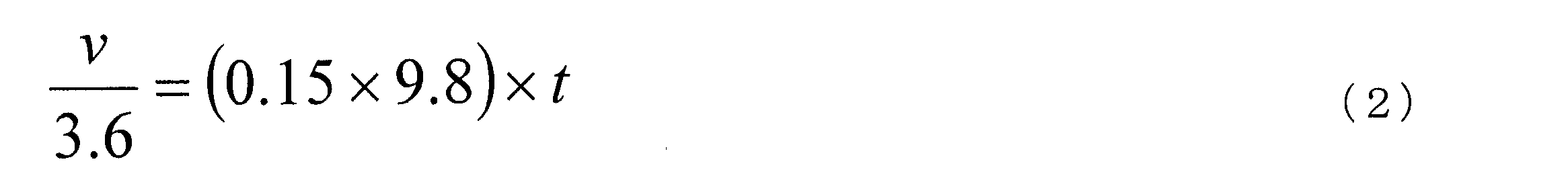

図5は、発明の他の実施形態に係る走行経路演算装置のブロック図である。本例では上述した第1実施形態に対して、逸脱量演算部8を有する点が異なる。これ以外の構成は上述した第1実施形態と同じであり、その記載を援用する。
2…走行経路演算部
3…情報取得部
4…距離測定部
5…車速推定部
6…認識判断部
7…回避箇所設定部
8…逸脱度演算部
Claims (11)
- 自車が目的地に到着するまでの走行経路を演算する走行経路演算手段と、
地物を検出する地物検出手段と、
前記自車の行動決定の際に前記自車が前記地物の認識のために必要とする、前記自車から前記地物までの距離を必要認識距離として測定する距離測定手段と、
前記地物検出手段の検出範囲及び前記必要認識距離に基づき、前記地物の認識の困難性を判断する判断手段とを備え、
前記走行経路演算手段は、前記判断手段により前記地物の認識が困難であると判断された箇所を回避した上で前記走行経路を演算する
ことを特徴とする走行経路演算装置。 - 請求項1記載の走行経路演算装置において、
前記判断手段は、前記自車に対して前記必要認識距離を離した箇所に位置する前記地物が前記検出範囲外に存在する場合には、前記地物の認識が困難であると判断する
ことを特徴とする走行経路演算装置。 - 請求項1又は2に記載の走行経路演算装置において、
前記自車の車速を推定する車速推定手段を備え、
前記距離測定手段は、前記車速に基づいて前記必要認識距離を測定する
ことを特徴とする走行経路演算装置。 - 請求項3記載の走行経路演算装置において、
前記車速推定手段は、前記走行経路の法定速度を前記車速として推定する
ことを特徴とする走行経路演算装置。 - 請求項3記載の走行経路演算装置において、
前記車速推定手段は、前記走行経路上の所定の道路を過去に走行したときの前記車速に基づき、前記所定の道路を走行する際の前記車速を推定する
ことを特徴とする走行経路演算装置。 - 請求項1~5のいずれか一項に記載の走行経路演算装置において、
前記検出範囲は、前記地物検出手段の典型値に応じて設定されている
ことを特徴とする走行経路演算装置。 - 請求項1~5のいずれか一項に記載の走行経路演算装置において、
前記検出範囲は、前記走行経路の混雑状態に応じて設定されている
ことを特徴とする走行経路演算装置。 - 請求項1~7のいずれか一項に記載の走行経路演算装置において、
前記距離測定手段は、前記自車の挙動に基づいて前記必要認識距離を測定する
ことを特徴とする走行経路演算装置。 - 請求項1~8のいずれか一項に記載の走行経路演算装置において、
前記判断手段は、
前記検出範囲に対して逸脱している前記必要認識距離の逸脱量を演算し、
前記逸脱量に基づいて前記地物の認識の困難性を判断する
ことを特徴とする走行経路演算装置。 - 請求項9に記載の走行経路演算装置において、
前記判断手段は、
前記自車の車速の減速量に基づいて前記逸脱量を演算する
ことを特徴とする走行経路演算装置。 - 請求項9又は10に記載の走行経路演算装置において、
前記判断手段は、
前記走行経路上の前記地物の各箇所で、複数の前記走行経路毎に前記逸脱量を演算し、
前記走行経路演算手段は、
前記複数の走行経路のうち、前記逸脱量の総和が最も高い走行経路、又は、所定値よりも高い前記逸脱量の数が最も多い走行経路を、前記自車の走行する前記走行経路として演算しない
ことを特徴とする走行経路演算装置。
Priority Applications (8)
| Application Number | Priority Date | Filing Date | Title |
|---|---|---|---|
| MX2017005117A MX359043B (es) | 2014-10-22 | 2014-10-22 | Dispositivo de cálculo de la ruta de desplazamiento. |
| CN201480082851.3A CN107076565B (zh) | 2014-10-22 | 2014-10-22 | 行驶路径运算装置 |
| RU2017116735A RU2660425C1 (ru) | 2014-10-22 | 2014-10-22 | Устройство вычисления маршрута движения |
| BR112017008088-5A BR112017008088B1 (pt) | 2014-10-22 | 2014-10-22 | Dispositivo de cálculo de rota de movimento |
| EP14904511.4A EP3211375B1 (en) | 2014-10-22 | 2014-10-22 | Travel route calculation apparatus |
| JP2016555008A JP6304393B2 (ja) | 2014-10-22 | 2014-10-22 | 走行経路演算装置 |
| US15/520,313 US10585435B2 (en) | 2014-10-22 | 2014-10-22 | Travel route calculation device |
| PCT/JP2014/078124 WO2016063384A1 (ja) | 2014-10-22 | 2014-10-22 | 走行経路演算装置 |
Applications Claiming Priority (1)
| Application Number | Priority Date | Filing Date | Title |
|---|---|---|---|
| PCT/JP2014/078124 WO2016063384A1 (ja) | 2014-10-22 | 2014-10-22 | 走行経路演算装置 |
Publications (1)
| Publication Number | Publication Date |
|---|---|
| WO2016063384A1 true WO2016063384A1 (ja) | 2016-04-28 |
Family
ID=55760453
Family Applications (1)
| Application Number | Title | Priority Date | Filing Date |
|---|---|---|---|
| PCT/JP2014/078124 WO2016063384A1 (ja) | 2014-10-22 | 2014-10-22 | 走行経路演算装置 |
Country Status (8)
| Country | Link |
|---|---|
| US (1) | US10585435B2 (ja) |
| EP (1) | EP3211375B1 (ja) |
| JP (1) | JP6304393B2 (ja) |
| CN (1) | CN107076565B (ja) |
| BR (1) | BR112017008088B1 (ja) |
| MX (1) | MX359043B (ja) |
| RU (1) | RU2660425C1 (ja) |
| WO (1) | WO2016063384A1 (ja) |
Cited By (1)
| Publication number | Priority date | Publication date | Assignee | Title |
|---|---|---|---|---|
| US10838422B2 (en) | 2017-04-13 | 2020-11-17 | Panasonic Intellectual Property Corporation Of America | Information processing method and information processing apparatus |
Families Citing this family (6)
| Publication number | Priority date | Publication date | Assignee | Title |
|---|---|---|---|---|
| WO2018209576A1 (en) | 2017-05-16 | 2018-11-22 | Beijing Didi Infinity Technology And Development Co., Ltd. | Systems and methods for digital route planning |
| KR101973627B1 (ko) * | 2017-07-11 | 2019-04-29 | 엘지전자 주식회사 | 차량에 구비된 차량 제어 장치 및 차량의 제어방법 |
| JP6664371B2 (ja) * | 2017-12-13 | 2020-03-13 | 本田技研工業株式会社 | 物体認識装置、物体認識方法及び車両 |
| US11847838B2 (en) * | 2018-09-25 | 2023-12-19 | Hitachi Astemo, Ltd. | Recognition device |
| US11402842B2 (en) | 2019-01-18 | 2022-08-02 | Baidu Usa Llc | Method to define safe drivable area for automated driving system |
| US11167751B2 (en) * | 2019-01-18 | 2021-11-09 | Baidu Usa Llc | Fail-operational architecture with functional safety monitors for automated driving system |
Citations (3)
| Publication number | Priority date | Publication date | Assignee | Title |
|---|---|---|---|---|
| JP2008157820A (ja) * | 2006-12-25 | 2008-07-10 | Fujitsu Ten Ltd | 標識情報提供装置 |
| JP2012247315A (ja) * | 2011-05-27 | 2012-12-13 | Zenrin Co Ltd | 経路案内装置 |
| JP2013083498A (ja) * | 2011-10-07 | 2013-05-09 | Mic Ware:Kk | ナビゲーション装置、ナビゲーション方法、およびプログラム |
Family Cites Families (16)
| Publication number | Priority date | Publication date | Assignee | Title |
|---|---|---|---|---|
| SU1679195A1 (ru) * | 1989-10-31 | 1991-09-23 | С.П.Ботуз с (53) 681.325,61 (088.8) | Устройство дл прогнозировани состо ни систем управлени |
| JP4724043B2 (ja) * | 2006-05-17 | 2011-07-13 | トヨタ自動車株式会社 | 対象物認識装置 |
| JP4680131B2 (ja) * | 2006-05-29 | 2011-05-11 | トヨタ自動車株式会社 | 自車位置測定装置 |
| RU2395122C2 (ru) * | 2006-11-15 | 2010-07-20 | Федеральное государственное образовательное учреждение высшего профессионального образования Мурманский государственный технический университет | Способ управления движением подвижных объектов |
| JP4984152B2 (ja) * | 2007-08-31 | 2012-07-25 | アイシン・エィ・ダブリュ株式会社 | 画像認識システム、サーバ装置、及び画像認識装置 |
| JP2009075010A (ja) * | 2007-09-21 | 2009-04-09 | Denso It Laboratory Inc | 経路長算出装置、経路長算出方法、経路長算出プログラム及び車両用空調装置ならびに移動物体搭載機器の制御装置 |
| JP2009257991A (ja) * | 2008-04-18 | 2009-11-05 | Denso Corp | カーナビゲーションシステム |
| JP5233606B2 (ja) * | 2008-11-19 | 2013-07-10 | 富士通株式会社 | 絶対移動経路算出装置及び方法、並びにプログラム |
| US20110190972A1 (en) * | 2010-02-02 | 2011-08-04 | Gm Global Technology Operations, Inc. | Grid unlock |
| WO2012014280A1 (ja) * | 2010-07-27 | 2012-02-02 | トヨタ自動車株式会社 | 運転支援装置 |
| US8509982B2 (en) * | 2010-10-05 | 2013-08-13 | Google Inc. | Zone driving |
| US9182761B2 (en) | 2011-08-25 | 2015-11-10 | Nissan Motor Co., Ltd. | Autonomous driving control system for vehicle |
| EP2765048A4 (en) * | 2011-10-03 | 2016-03-09 | Toyota Motor Co Ltd | FAILSAFE SYSTEM FOR ONE VEHICLE |
| CN102944246B (zh) * | 2012-10-30 | 2015-07-29 | 湖南赛格导航技术研究有限公司 | 车辆行驶线路偏移监控系统 |
| RU128747U1 (ru) * | 2012-12-25 | 2013-05-27 | Открытое Акционерное Общество "Российские Железные Дороги" | Устройство для сбора данных путевых объектов и установленных скоростей движения для систем автоведения и безопасности |
| US10124800B2 (en) * | 2014-05-30 | 2018-11-13 | The Boeing Company | Variably controlled ground vehicle |
-
2014
- 2014-10-22 CN CN201480082851.3A patent/CN107076565B/zh active Active
- 2014-10-22 EP EP14904511.4A patent/EP3211375B1/en active Active
- 2014-10-22 WO PCT/JP2014/078124 patent/WO2016063384A1/ja active Application Filing
- 2014-10-22 US US15/520,313 patent/US10585435B2/en active Active
- 2014-10-22 MX MX2017005117A patent/MX359043B/es active IP Right Grant
- 2014-10-22 BR BR112017008088-5A patent/BR112017008088B1/pt active IP Right Grant
- 2014-10-22 JP JP2016555008A patent/JP6304393B2/ja active Active
- 2014-10-22 RU RU2017116735A patent/RU2660425C1/ru active
Patent Citations (3)
| Publication number | Priority date | Publication date | Assignee | Title |
|---|---|---|---|---|
| JP2008157820A (ja) * | 2006-12-25 | 2008-07-10 | Fujitsu Ten Ltd | 標識情報提供装置 |
| JP2012247315A (ja) * | 2011-05-27 | 2012-12-13 | Zenrin Co Ltd | 経路案内装置 |
| JP2013083498A (ja) * | 2011-10-07 | 2013-05-09 | Mic Ware:Kk | ナビゲーション装置、ナビゲーション方法、およびプログラム |
Non-Patent Citations (1)
| Title |
|---|
| See also references of EP3211375A4 * |
Cited By (1)
| Publication number | Priority date | Publication date | Assignee | Title |
|---|---|---|---|---|
| US10838422B2 (en) | 2017-04-13 | 2020-11-17 | Panasonic Intellectual Property Corporation Of America | Information processing method and information processing apparatus |
Also Published As
| Publication number | Publication date |
|---|---|
| MX2017005117A (es) | 2017-07-14 |
| RU2660425C1 (ru) | 2018-07-06 |
| EP3211375A4 (en) | 2018-01-24 |
| JP6304393B2 (ja) | 2018-04-04 |
| BR112017008088A2 (pt) | 2017-12-19 |
| US20170322557A1 (en) | 2017-11-09 |
| BR112017008088B1 (pt) | 2022-04-05 |
| CN107076565A (zh) | 2017-08-18 |
| EP3211375A1 (en) | 2017-08-30 |
| JPWO2016063384A1 (ja) | 2017-09-21 |
| MX359043B (es) | 2018-09-13 |
| US10585435B2 (en) | 2020-03-10 |
| CN107076565B (zh) | 2020-03-17 |
| EP3211375B1 (en) | 2022-02-09 |
Similar Documents
| Publication | Publication Date | Title |
|---|---|---|
| JP6304393B2 (ja) | 走行経路演算装置 | |
| JP6399100B2 (ja) | 走行経路演算装置 | |
| JP6323565B2 (ja) | 運転支援装置 | |
| CN110667578B (zh) | 自动驾驶车辆的横向决策系统及横向决策确定方法 | |
| US10703362B2 (en) | Autonomous driving autonomous system, automated driving assistance method, and computer program | |
| US10239539B2 (en) | Vehicle travel control method and vehicle travel control device | |
| US8346463B2 (en) | Driving aid system and method of creating a model of surroundings of a vehicle | |
| KR20190014871A (ko) | 차량의 후방에 위치한 응급 차량에 기초하여 상기 차량의 주행 경로를 변경하는 장치 및 방법 | |
| US20190156664A1 (en) | Safety driving assistant system, server, vehicle and program | |
| KR20200075915A (ko) | 차량의 주행 제어 장치 및 그 방법 | |
| US20190130742A1 (en) | Safety drving assistant system, vehicle, and program | |
| US20180043897A1 (en) | Autonomous driving system | |
| WO2020066505A1 (ja) | 認識装置 | |
| JP5565303B2 (ja) | 運転支援装置及び運転支援方法 | |
| US11161506B2 (en) | Travel support device and non-transitory computer-readable medium | |
| JP2013019680A (ja) | 走行制御装置 | |
| CN109425861B (zh) | 本车位置可信度运算装置 | |
| CN114475649A (zh) | 自动驾驶控制装置和自动驾驶控制方法 | |
| JP2023168399A (ja) | 地図データ生成方法 | |
| JP7019259B2 (ja) | 運転支援方法及び運転支援装置 | |
| KR20220136679A (ko) | 주행 제어 장치 및 방법 | |
| JP2021101268A (ja) | 自動運転車 | |
| JPWO2020053612A1 (ja) | 車両挙動予測方法及び車両挙動予測装置 | |
| KR20230045391A (ko) | 교통 흐름 방해 타겟 검출 장치 및 그 방법 | |
| JP2021041801A (ja) | 走行軌道推定方法、車両制御方法及び走行軌道推定装置 |
Legal Events
| Date | Code | Title | Description |
|---|---|---|---|
| 121 | Ep: the epo has been informed by wipo that ep was designated in this application |
Ref document number: 14904511 Country of ref document: EP Kind code of ref document: A1 |
|
| ENP | Entry into the national phase |
Ref document number: 2016555008 Country of ref document: JP Kind code of ref document: A |
|
| WWE | Wipo information: entry into national phase |
Ref document number: 15520313 Country of ref document: US |
|
| WWE | Wipo information: entry into national phase |
Ref document number: MX/A/2017/005117 Country of ref document: MX |
|
| NENP | Non-entry into the national phase |
Ref country code: DE |
|
| REEP | Request for entry into the european phase |
Ref document number: 2014904511 Country of ref document: EP |
|
| ENP | Entry into the national phase |
Ref document number: 2017116735 Country of ref document: RU Kind code of ref document: A |
|
| REG | Reference to national code |
Ref country code: BR Ref legal event code: B01A Ref document number: 112017008088 Country of ref document: BR |
|
| ENP | Entry into the national phase |
Ref document number: 112017008088 Country of ref document: BR Kind code of ref document: A2 Effective date: 20170419 |