WO2016060018A1 - ディーゼルエンジンの停止装置 - Google Patents
ディーゼルエンジンの停止装置 Download PDFInfo
- Publication number
- WO2016060018A1 WO2016060018A1 PCT/JP2015/078359 JP2015078359W WO2016060018A1 WO 2016060018 A1 WO2016060018 A1 WO 2016060018A1 JP 2015078359 W JP2015078359 W JP 2015078359W WO 2016060018 A1 WO2016060018 A1 WO 2016060018A1
- Authority
- WO
- WIPO (PCT)
- Prior art keywords
- engine
- stop
- phase
- time
- engine stop
- Prior art date
Links
Images


Classifications
-
- F—MECHANICAL ENGINEERING; LIGHTING; HEATING; WEAPONS; BLASTING
- F02—COMBUSTION ENGINES; HOT-GAS OR COMBUSTION-PRODUCT ENGINE PLANTS
- F02D—CONTROLLING COMBUSTION ENGINES
- F02D41/00—Electrical control of supply of combustible mixture or its constituents
- F02D41/30—Controlling fuel injection
- F02D41/38—Controlling fuel injection of the high pressure type
- F02D41/3809—Common rail control systems
-
- F—MECHANICAL ENGINEERING; LIGHTING; HEATING; WEAPONS; BLASTING
- F02—COMBUSTION ENGINES; HOT-GAS OR COMBUSTION-PRODUCT ENGINE PLANTS
- F02D—CONTROLLING COMBUSTION ENGINES
- F02D17/00—Controlling engines by cutting out individual cylinders; Rendering engines inoperative or idling
- F02D17/04—Controlling engines by cutting out individual cylinders; Rendering engines inoperative or idling rendering engines inoperative or idling, e.g. caused by abnormal conditions
-
- F—MECHANICAL ENGINEERING; LIGHTING; HEATING; WEAPONS; BLASTING
- F02—COMBUSTION ENGINES; HOT-GAS OR COMBUSTION-PRODUCT ENGINE PLANTS
- F02D—CONTROLLING COMBUSTION ENGINES
- F02D41/00—Electrical control of supply of combustible mixture or its constituents
- F02D41/009—Electrical control of supply of combustible mixture or its constituents using means for generating position or synchronisation signals
-
- F—MECHANICAL ENGINEERING; LIGHTING; HEATING; WEAPONS; BLASTING
- F02—COMBUSTION ENGINES; HOT-GAS OR COMBUSTION-PRODUCT ENGINE PLANTS
- F02D—CONTROLLING COMBUSTION ENGINES
- F02D41/00—Electrical control of supply of combustible mixture or its constituents
- F02D41/02—Circuit arrangements for generating control signals
- F02D41/04—Introducing corrections for particular operating conditions
- F02D41/042—Introducing corrections for particular operating conditions for stopping the engine
-
- F—MECHANICAL ENGINEERING; LIGHTING; HEATING; WEAPONS; BLASTING
- F02—COMBUSTION ENGINES; HOT-GAS OR COMBUSTION-PRODUCT ENGINE PLANTS
- F02N—STARTING OF COMBUSTION ENGINES; STARTING AIDS FOR SUCH ENGINES, NOT OTHERWISE PROVIDED FOR
- F02N19/00—Starting aids for combustion engines, not otherwise provided for
- F02N19/005—Aiding engine start by starting from a predetermined position, e.g. pre-positioning or reverse rotation
-
- F—MECHANICAL ENGINEERING; LIGHTING; HEATING; WEAPONS; BLASTING
- F02—COMBUSTION ENGINES; HOT-GAS OR COMBUSTION-PRODUCT ENGINE PLANTS
- F02D—CONTROLLING COMBUSTION ENGINES
- F02D41/00—Electrical control of supply of combustible mixture or its constituents
- F02D41/30—Controlling fuel injection
- F02D41/38—Controlling fuel injection of the high pressure type
- F02D2041/389—Controlling fuel injection of the high pressure type for injecting directly into the cylinder
-
- F—MECHANICAL ENGINEERING; LIGHTING; HEATING; WEAPONS; BLASTING
- F02—COMBUSTION ENGINES; HOT-GAS OR COMBUSTION-PRODUCT ENGINE PLANTS
- F02N—STARTING OF COMBUSTION ENGINES; STARTING AIDS FOR SUCH ENGINES, NOT OTHERWISE PROVIDED FOR
- F02N19/00—Starting aids for combustion engines, not otherwise provided for
- F02N19/005—Aiding engine start by starting from a predetermined position, e.g. pre-positioning or reverse rotation
- F02N2019/008—Aiding engine start by starting from a predetermined position, e.g. pre-positioning or reverse rotation the engine being stopped in a particular position
Definitions
- the present invention relates to a diesel engine stop device that can control the piston position of a cylinder when the diesel engine is stopped and start the engine quickly at the next restart.
- the fuel injectors provided in each cylinder are electronically controlled, so that the injection timing and injection time of high-pressure fuel can be accurately controlled, and fine injection such as pre-injection and after-injection before main injection Can be done.
- JP 2004-301078 A JP 2004-124753 A JP 2004-124754 A Special table 2003-532005 gazette Special table 2003-532006 gazette JP 2003-314341 A Japanese Patent Application Laid-Open No. 2004-263569
- FIG. 5 (a) shows a state when the piston stop position of an arbitrary cylinder is stopped in a range of 274 ° to 292 °, for example, with respect to the rotation of the crankshaft.
- Patent Documents 1 to 5 even if the piston of each cylinder stops at an arbitrary position, the timing of fuel injection to the cylinder is controlled at the time of engine start to improve the startability. Due to the control, there is a problem that the starting time becomes long.
- an object of the present invention is to provide a diesel engine stop device capable of controlling the piston stop position so that the common restart type diesel engine can quickly perform the next restart when the engine is stopped in the common rail diesel engine. It is in.
- the present invention is designed to finely adjust the fuel injected from the fuel injector in synchronism with the engine phase when the common rail diesel engine is stopped, so that the piston of a specific cylinder is dead in the compression stroke.
- a diesel engine stop device characterized by being stopped at a point.
- the present invention is also a diesel engine stop device for controlling the piston position of each cylinder so as to shorten the next restartability when the common rail diesel engine is stopped, and detects the crank angle of the crankshaft.
- the cam shaft angle detection means for detecting the angle of the cam shaft for opening and closing the intake / exhaust valve, the crank angle from the crank angle detection means and the cam shaft angle from the cam shaft angle detection means
- the engine phase determination means for determining the engine phase, the stop time from the engine stop request time to the engine stop is stored, and based on the engine phase and the stop time input from the engine phase determination means at the engine stop request time
- Engine stop position determination means for obtaining an engine phase when the engine is stopped, and the engine after the engine stop request
- a stop-time injector control means for controlling the fuel injected from the fuel injector so that the engine phase when the engine is stopped determined by the stop position determination means is stopped at the bottom dead center of the compression stroke
- a stop device for a diesel engine comprising:
- the engine phase determining means preferably specifies the cylinder at the compression bottom dead center that moves from the intake stroke to the compression stroke from the engine phase when the engine stop request is made.
- the engine stop position determining means is configured such that when the engine phase obtained at the time of the engine stop request is an engine phase in which there is no cylinder at the compression bottom dead center in which the intake stroke shifts to the compression stroke, the specific cylinder has the intake stroke at the stop time. It is preferable to determine the phase shift amount of the specific cylinder from the engine stop request so as to be positioned at the compression bottom dead center from the engine to the compression stroke.
- the engine stop position determining means changes the shift amount so that a specific cylinder located at a compression bottom dead center that shifts from the intake stroke to the compression stroke during the stop time sequentially becomes a different cylinder for each engine stop request. Is preferred.
- the stop-time injector control means finely adjusts the fuel injection amount in each fuel injector based on the deviation amount of the engine phase of the specific cylinder from the engine stop position determination means, and performs fuel injection according to the engine stop request. It is preferable to control the stop time.
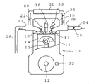
- FIG. 1 It is a figure which shows one Embodiment of the stop apparatus of the diesel engine of this invention. It is a schematic sectional drawing of the diesel engine shown in FIG.
- the diesel engine stop device of the present invention it is a diagram showing the vehicle speed when the engine is stopped, the engine rotation, and the piston state of each cylinder (cylinder).
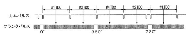
- the stop device of the diesel engine of this invention it is a figure which shows the cam pulse of a cam shaft sensor, and the crank pulse of a crank angle sensor.
- (a) illustrates the engine stop position
- (b) illustrates engine start at the engine stop position of (a).
- a four-cylinder diesel engine 10 will be described with reference to FIGS. 1 and 2 as an example of a common rail type diesel engine.
- the cylinder block 11 of the diesel engine 10 is provided with a piston 14 that moves up and down via a crankshaft 12 and a connecting rod 13 for each of the cylinders # 1 to # 4.
- the cylinder head 15 on the cylinder block 11 is provided with a fuel injector 16 for injecting fuel for each of the cylinders # 1 to # 4, and an intake valve 17 and an exhaust valve 18.
- the fuel injector 16 is supplied with high-pressure fuel from the common rail 19, and the ECU 20 is controlled to open and close the fuel injector 16.
- the fuel injection timing and injection time (injection amount) in each cylinder # 1 to # 4 are determined. To be controlled.
- the intake valve 17 and the exhaust valve 18 are controlled to be opened and closed by a valve gear 22 including a rocker arm and a cam.
- the intake air to the diesel engine 10 is adjusted by the intake throttle valve 25 from the intake pipe 24 and is taken into the cylinders # 1 to # 4 from the intake manifold 26 via the intake valve 17. Exhaust gas from the cylinders # 1 to # 4 is exhausted to the exhaust manifold 27 through the exhaust valve 18 and then exhausted to the exhaust pipe 28. A part of the exhaust from the exhaust manifold 27 is recirculated to the intake manifold 26 via the EGR pipe 29, the EGR cooler 30, and the EGR valve 31.
- the crankshaft 12 is provided with a crank angle sensor 32 for detecting the rotation angle of the crankshaft 12, and the valve gear 22 is provided with a camshaft sensor 33 for detecting the rotation angle of the camshaft.
- the detected value is input to the ECU 20.
- the ECU 20 is connected with a key switch 35 for starting and stopping the diesel engine 10.
- the ECU 20 starts the diesel engine 10 when the key switch 35 is turned on, stops fuel injection from the fuel injector 16 when the key switch 35 is turned off, and stops the engine.
- the ECU 20 includes a crank angle detection unit 40 to which a detection value of the crank angle sensor 32 is input, a cam shaft angle detection unit 41 to which a detection value of the cam shaft sensor 33 is input, and a crank angle from the crank angle detection unit 40.
- Engine phase determination means 42 for determining the engine phase based on the camshaft angle detection means 41 and the camshaft angle detection means 41, and the stop time from the engine stop request time to the engine stop request are stored.
- the engine stop position determination means 43 Based on the engine phase and stop time input from the phase determination means 42, the engine stop position determination means 43 for obtaining the engine phase when the engine is stopped, and the engine determined by the engine stop position determination means 43 after the engine stop request.
- the engine phase is such that the piston of a particular cylinder stops at the bottom dead center of the compression stroke.
- FIG. 4 shows a crank pulse inputted from the crank angle sensor 32 to the crank angle detecting means 40, a cam pulse inputted from the cam shaft sensor 33 to the cam shaft angle detecting means 41, and top dead centers of the cylinders # 1 to # 4. (TDC) is shown.
- the crank angle sensor 32 and the camshaft sensor 33 are gear tooth sensors.
- the crank pulse is output according to the teeth of the gear provided on the crankshaft, and the pulse by the teeth is not output when the crankshaft is at a position of 0 ° (360 °).
- the cam pulse detects the gear teeth provided on the camshaft that rotates at half the rotation of the crankshaft and outputs a pulse.
- the crankshaft rotates twice (720 °)
- the camshaft makes one rotation.
- a pulse is output every rotation of 180 °, and two pulses are continuously output at 0 ° and 720 ° of the crankshaft.
- the cylinder # 1 when the crank angle is 90 °, the cylinder # 1 is top dead center (TDC), and when the crank angle is 270 °, the cylinder # 3 is top dead center (TDC), and when the crank angle is 450 °, the cylinder # 4 indicates the top dead center (TDC), and when the crank angle is 630 °, the cylinder # 2 is the top dead center (TDC).
- the engine phase determination means 42 determines the engine phase, that is, the piston position of each cylinder # 1 to # 4, based on the crank angle from the crank angle detection means 40 and the camshaft rotation from the camshaft angle detection means 41. be able to.
- FIG. 3A shows changes in the vehicle speed and changes in the engine speed when the vehicle stops running, the engine stop request is made and the engine is stopped, and then restarted.
- FIG. show the transition of the bottom dead center of the pistons of the cylinders # 1 to # 4 from when the engine stop request is made until the engine stops.
- FIG. 3B shows a change in the engine phase when an engine stop request is made, that is, a change in the cylinder where the pistons of the cylinders # 1 to # 4 are at bottom dead center.
- the area surrounded by diagonal lines indicates the bottom dead center vicinity area of the bottom dead center ⁇ 45 °, and when the engine stop request is made, the piston of the cylinder # 2 is at the bottom dead center.
- the bottom dead center changes from cylinder # 1 ⁇ # 3 ⁇ # 4 ⁇ # 2 and indicates that cylinder # 4 is positioned at the bottom dead center when the engine is stopped after the stop time ST has elapsed.
- the engine When the engine is restarted after this stop, it can be restarted with a single compression stroke after cranking, and the engine restart time can be shortened.
- FIG. 3B shows an example in which when the engine stop request is made, the piston of the cylinder # 2 is at the bottom dead center and the cylinder # 4 is positioned at the bottom dead center at the stop time ST.
- the stop request is 1, the cylinder # 2 is at the bottom dead center at the stop time ST.
- the cylinder # 1 is at the bottom dead center at the cylinder # 3
- the cylinder # 3 is at the bottom dead center at the cylinder # 4.
- the engine phase is various, and the engine stop request is not made in the state shown in FIG. 3B.
- the cylinder phase # 1 to # 4 at the compression bottom dead center that moves from the intake stroke to the compression stroke is specified from the engine phase at the time of being made, and if there is no cylinder at the compression bottom dead center when the engine stop request is made,
- a specific cylinder for example, a cylinder that moves to the compression bottom dead center that moves from the intake stroke to the compression stroke next is specified, and the cylinder is positioned at the compression bottom dead center that moves from the intake stroke to the compression stroke at the stop time ST.
- the phase shift amount (time) is preferably obtained from the engine stop request.
- the stop-time injector control means 44 finely adjusts the fuel injection amount in each fuel injector 16 based on the amount of deviation of the engine phase from the engine stop position determination means 43 to control the fuel injection stop timing according to the engine stop request. To do. That is, by finely adjusting the fuel injection amount in each fuel injector 16 and controlling the fuel injection stop timing, the piston of the cylinder # 2 is at the bottom dead center as described in FIG. By setting the same state as when the engine stop request is made, it is possible to position the cylinder # 4 at the bottom dead center after the stop time ST has elapsed.
- the fuel injection stop timing is controlled by slightly adjusting the fuel injection amount from the fuel injector 16 to each of the cylinders # 1 to # 4.
- the bottom dead center position of the cylinders # 1 to # 4 can be controlled.
- the engine stop position is determined.
- the means 43 changes the shift amount so that the specific cylinder located at the compression bottom dead center that shifts from the intake stroke to the compression stroke at the stop time ST sequentially changes to a different cylinder for each engine stop request, and sequentially restarts.
Landscapes
- Engineering & Computer Science (AREA)
- Chemical & Material Sciences (AREA)
- Combustion & Propulsion (AREA)
- Mechanical Engineering (AREA)
- General Engineering & Computer Science (AREA)
- Output Control And Ontrol Of Special Type Engine (AREA)
- Electrical Control Of Air Or Fuel Supplied To Internal-Combustion Engine (AREA)
- Combined Controls Of Internal Combustion Engines (AREA)
- Control Of Vehicle Engines Or Engines For Specific Uses (AREA)
Priority Applications (3)
| Application Number | Priority Date | Filing Date | Title |
|---|---|---|---|
| EP15850841.6A EP3208451B1 (de) | 2014-10-17 | 2015-10-06 | Vorrichtung zum anhalten eines dieselmotors |
| US15/519,795 US10145327B2 (en) | 2014-10-17 | 2015-10-06 | Device for stopping diesel engine |
| CN201580056290.4A CN107076043B (zh) | 2014-10-17 | 2015-10-06 | 柴油引擎的停止装置 |
Applications Claiming Priority (2)
| Application Number | Priority Date | Filing Date | Title |
|---|---|---|---|
| JP2014212651A JP6435767B2 (ja) | 2014-10-17 | 2014-10-17 | ディーゼルエンジンの停止装置 |
| JP2014-212651 | 2014-10-17 |
Publications (1)
| Publication Number | Publication Date |
|---|---|
| WO2016060018A1 true WO2016060018A1 (ja) | 2016-04-21 |
Family
ID=55746565
Family Applications (1)
| Application Number | Title | Priority Date | Filing Date |
|---|---|---|---|
| PCT/JP2015/078359 WO2016060018A1 (ja) | 2014-10-17 | 2015-10-06 | ディーゼルエンジンの停止装置 |
Country Status (5)
| Country | Link |
|---|---|
| US (1) | US10145327B2 (de) |
| EP (1) | EP3208451B1 (de) |
| JP (1) | JP6435767B2 (de) |
| CN (1) | CN107076043B (de) |
| WO (1) | WO2016060018A1 (de) |
Families Citing this family (5)
| Publication number | Priority date | Publication date | Assignee | Title |
|---|---|---|---|---|
| GB2557641A (en) * | 2016-12-14 | 2018-06-27 | Jaguar Land Rover Ltd | Internal combustion engine control method and apparatus |
| DE102017221320A1 (de) * | 2017-11-28 | 2019-05-29 | Bayerische Motoren Werke Aktiengesellschaft | Verfahren und Steuereinheit zur Durchführung eines Motorstopps eines Verbrennungsmotors |
| GB2570709B (en) * | 2018-02-05 | 2020-05-13 | Ford Global Tech Llc | Controller for a crankshaft of an internal combustion engine in a hybrid vehicle |
| CN108894902A (zh) * | 2018-07-16 | 2018-11-27 | 清华大学 | 一种混合动力专用发动机的起停控制方法 |
| US11572844B2 (en) * | 2020-02-24 | 2023-02-07 | Ford Global Technologies, Llc | Methods and system for stopping an internal combustion engine |
Citations (9)
| Publication number | Priority date | Publication date | Assignee | Title |
|---|---|---|---|---|
| JP2000045827A (ja) * | 1998-07-24 | 2000-02-15 | Toyota Motor Corp | 内燃機関の吸気絞り弁制御装置 |
| JP2004263566A (ja) * | 2003-01-27 | 2004-09-24 | Toyota Motor Corp | 内燃機関の停止制御装置 |
| JP2006057524A (ja) * | 2004-08-19 | 2006-03-02 | Denso Corp | エンジン回転停止制御装置 |
| JP2007092549A (ja) * | 2005-09-27 | 2007-04-12 | Toyota Motor Corp | 内燃機関の停止制御装置 |
| JP2008095655A (ja) * | 2006-10-16 | 2008-04-24 | Mazda Motor Corp | エンジンの制御装置 |
| JP2009062959A (ja) * | 2007-09-10 | 2009-03-26 | Mazda Motor Corp | ディーゼルエンジンの制御装置 |
| JP2011112015A (ja) * | 2009-11-30 | 2011-06-09 | Isuzu Motors Ltd | 内燃機関の制御方法および内燃機関 |
| JP2013095154A (ja) * | 2011-10-27 | 2013-05-20 | Toyota Motor Corp | 車両制御システム及び制御装置 |
| JP2013204440A (ja) * | 2012-03-27 | 2013-10-07 | Isuzu Motors Ltd | ディーゼルエンジンの始動装置及び始動方法 |
Family Cites Families (16)
| Publication number | Priority date | Publication date | Assignee | Title |
|---|---|---|---|---|
| US5870550A (en) | 1996-02-26 | 1999-02-09 | Network Engineering Software | Web server employing multi-homed, moldular framework |
| DE10020104A1 (de) | 2000-04-22 | 2001-10-31 | Bosch Gmbh Robert | Verfahren zum Starten einer mehrzylindrigen Brennkraftmaschine |
| DE10020325A1 (de) | 2000-04-26 | 2001-11-08 | Bosch Gmbh Robert | Verfahren zum Starten einer mehrzylindrigen Brennkraftmaschine |
| JP3896952B2 (ja) | 2002-02-22 | 2007-03-22 | トヨタ自動車株式会社 | 駆動装置 |
| JP3743414B2 (ja) | 2002-09-30 | 2006-02-08 | マツダ株式会社 | エンジンの始動装置 |
| JP3852389B2 (ja) | 2002-09-30 | 2006-11-29 | マツダ株式会社 | エンジンの始動装置 |
| EP1403511A1 (de) | 2002-09-30 | 2004-03-31 | Mazda Motor Corporation | Verbrennungsmotor-Anlassersystem |
| JP3951924B2 (ja) * | 2003-01-31 | 2007-08-01 | トヨタ自動車株式会社 | 内燃機関の停止始動制御装置 |
| US7263959B2 (en) | 2003-01-27 | 2007-09-04 | Toyota Jidosha Kabushiki Kaisha | Control apparatus of internal combustion engine |
| DE10310301A1 (de) * | 2003-03-10 | 2004-09-23 | Robert Bosch Gmbh | Verfahren und Steuerung eines Verbrennungsmotors in einem Start-Stopp-Betrieb |
| JP3945441B2 (ja) | 2003-03-31 | 2007-07-18 | マツダ株式会社 | エンジンの始動装置 |
| CN102971513B (zh) | 2010-06-30 | 2015-08-26 | 马自达汽车株式会社 | 压缩自点火引擎的起动装置和起动方法 |
| EP2719882A4 (de) * | 2011-06-09 | 2016-04-20 | Toyota Motor Co Ltd | Motorsteuerungsvorrichtung |
| JP5554295B2 (ja) * | 2011-07-28 | 2014-07-23 | 日立オートモティブシステムズ株式会社 | 内燃機関の燃焼騒音検出方法及び燃焼騒音検出装置並びに内燃機関の制御装置 |
| JP5919697B2 (ja) * | 2011-09-26 | 2016-05-18 | マツダ株式会社 | ディーゼルエンジンの始動制御装置 |
| DE102011084635A1 (de) * | 2011-10-17 | 2013-04-18 | Robert Bosch Gmbh | Verfahren zum Betrieb einer Brennkraftmaschine und Recheneinheit |
-
2014
- 2014-10-17 JP JP2014212651A patent/JP6435767B2/ja active Active
-
2015
- 2015-10-06 US US15/519,795 patent/US10145327B2/en active Active
- 2015-10-06 EP EP15850841.6A patent/EP3208451B1/de active Active
- 2015-10-06 WO PCT/JP2015/078359 patent/WO2016060018A1/ja active Application Filing
- 2015-10-06 CN CN201580056290.4A patent/CN107076043B/zh active Active
Patent Citations (9)
| Publication number | Priority date | Publication date | Assignee | Title |
|---|---|---|---|---|
| JP2000045827A (ja) * | 1998-07-24 | 2000-02-15 | Toyota Motor Corp | 内燃機関の吸気絞り弁制御装置 |
| JP2004263566A (ja) * | 2003-01-27 | 2004-09-24 | Toyota Motor Corp | 内燃機関の停止制御装置 |
| JP2006057524A (ja) * | 2004-08-19 | 2006-03-02 | Denso Corp | エンジン回転停止制御装置 |
| JP2007092549A (ja) * | 2005-09-27 | 2007-04-12 | Toyota Motor Corp | 内燃機関の停止制御装置 |
| JP2008095655A (ja) * | 2006-10-16 | 2008-04-24 | Mazda Motor Corp | エンジンの制御装置 |
| JP2009062959A (ja) * | 2007-09-10 | 2009-03-26 | Mazda Motor Corp | ディーゼルエンジンの制御装置 |
| JP2011112015A (ja) * | 2009-11-30 | 2011-06-09 | Isuzu Motors Ltd | 内燃機関の制御方法および内燃機関 |
| JP2013095154A (ja) * | 2011-10-27 | 2013-05-20 | Toyota Motor Corp | 車両制御システム及び制御装置 |
| JP2013204440A (ja) * | 2012-03-27 | 2013-10-07 | Isuzu Motors Ltd | ディーゼルエンジンの始動装置及び始動方法 |
Also Published As
| Publication number | Publication date |
|---|---|
| US20170241365A1 (en) | 2017-08-24 |
| CN107076043A (zh) | 2017-08-18 |
| JP2016079907A (ja) | 2016-05-16 |
| CN107076043B (zh) | 2020-11-10 |
| EP3208451A1 (de) | 2017-08-23 |
| US10145327B2 (en) | 2018-12-04 |
| EP3208451B1 (de) | 2020-04-15 |
| JP6435767B2 (ja) | 2018-12-12 |
| EP3208451A4 (de) | 2018-07-04 |
Similar Documents
| Publication | Publication Date | Title |
|---|---|---|
| US9163568B2 (en) | Cold start systems and methods | |
| WO2016060018A1 (ja) | ディーゼルエンジンの停止装置 | |
| JP5919697B2 (ja) | ディーゼルエンジンの始動制御装置 | |
| US9249764B2 (en) | Engine control systems and methods with humidity sensors | |
| US9903332B2 (en) | Control device of multi-cylinder internal combustion engine | |
| US7322342B2 (en) | Control device of in-cylinder direct-injection internal combustion engine | |
| US10072628B2 (en) | Control device for internal combustion engine | |
| RU2669890C2 (ru) | Способ для запуска двигателя | |
| US6230687B1 (en) | Method for fuel injection for starting an internal combustion engine | |
| JP4736947B2 (ja) | 内燃機関の始動制御装置及び始動制御方法 | |
| JP2011144782A (ja) | 可変動弁機構を備える内燃機関の制御装置 | |
| JP2007327399A (ja) | 内燃機関の制御装置 | |
| JP2006283652A (ja) | エンジン始動制御装置 | |
| JP2009222002A (ja) | ディーゼルエンジンの自動停止装置 | |
| JP7171531B2 (ja) | 燃料噴射制御装置 | |
| JP6024603B2 (ja) | 内燃機関の制御装置 | |
| CN106894931B (zh) | 用于在没有从外部输送的转矩的情况下重新起动具有进气管喷射机构的多缸燃烧马达的方法 | |
| JP5892700B2 (ja) | 内燃機関の燃料噴射制御装置 | |
| JP2017155597A (ja) | 内燃機関の制御装置 | |
| JP2008095519A (ja) | エンジンの停止制御装置 | |
| US11002163B2 (en) | Valve timing controller and valve timing control method | |
| JP5857829B2 (ja) | 圧縮自己着火式エンジンの始動制御装置 | |
| JP2016125353A (ja) | エンジンの回転停止位置制御装置 | |
| JP2017219019A (ja) | 内燃機関の制御装置 | |
| WO2012133435A1 (ja) | 燃料噴射制御装置 |
Legal Events
| Date | Code | Title | Description |
|---|---|---|---|
| 121 | Ep: the epo has been informed by wipo that ep was designated in this application |
Ref document number: 15850841 Country of ref document: EP Kind code of ref document: A1 |
|
| WWE | Wipo information: entry into national phase |
Ref document number: 15519795 Country of ref document: US |
|
| NENP | Non-entry into the national phase |
Ref country code: DE |
|
| REEP | Request for entry into the european phase |
Ref document number: 2015850841 Country of ref document: EP |