WO2016035358A1 - Machine électrique tournante sans noyau à stator comprenant une bobine cylindrique et procédé de refroidissement associé - Google Patents
Machine électrique tournante sans noyau à stator comprenant une bobine cylindrique et procédé de refroidissement associé Download PDFInfo
- Publication number
- WO2016035358A1 WO2016035358A1 PCT/JP2015/056310 JP2015056310W WO2016035358A1 WO 2016035358 A1 WO2016035358 A1 WO 2016035358A1 JP 2015056310 W JP2015056310 W JP 2015056310W WO 2016035358 A1 WO2016035358 A1 WO 2016035358A1
- Authority
- WO
- WIPO (PCT)
- Prior art keywords
- gap
- mount
- cylindrical
- air passage
- forming body
- Prior art date
Links
Images


Classifications
-
- H—ELECTRICITY
- H02—GENERATION; CONVERSION OR DISTRIBUTION OF ELECTRIC POWER
- H02K—DYNAMO-ELECTRIC MACHINES
- H02K3/00—Details of windings
- H02K3/46—Fastening of windings on the stator or rotor structure
- H02K3/47—Air-gap windings, i.e. iron-free windings
-
- H—ELECTRICITY
- H02—GENERATION; CONVERSION OR DISTRIBUTION OF ELECTRIC POWER
- H02K—DYNAMO-ELECTRIC MACHINES
- H02K3/00—Details of windings
- H02K3/04—Windings characterised by the conductor shape, form or construction, e.g. with bar conductors
- H02K3/24—Windings characterised by the conductor shape, form or construction, e.g. with bar conductors with channels or ducts for cooling medium between the conductors
-
- H—ELECTRICITY
- H02—GENERATION; CONVERSION OR DISTRIBUTION OF ELECTRIC POWER
- H02K—DYNAMO-ELECTRIC MACHINES
- H02K1/00—Details of the magnetic circuit
- H02K1/06—Details of the magnetic circuit characterised by the shape, form or construction
- H02K1/22—Rotating parts of the magnetic circuit
- H02K1/27—Rotor cores with permanent magnets
- H02K1/2706—Inner rotors
- H02K1/272—Inner rotors the magnetisation axis of the magnets being perpendicular to the rotor axis
- H02K1/274—Inner rotors the magnetisation axis of the magnets being perpendicular to the rotor axis the rotor consisting of two or more circumferentially positioned magnets
- H02K1/2753—Inner rotors the magnetisation axis of the magnets being perpendicular to the rotor axis the rotor consisting of two or more circumferentially positioned magnets the rotor consisting of magnets or groups of magnets arranged with alternating polarity
- H02K1/278—Surface mounted magnets; Inset magnets
-
- H—ELECTRICITY
- H02—GENERATION; CONVERSION OR DISTRIBUTION OF ELECTRIC POWER
- H02K—DYNAMO-ELECTRIC MACHINES
- H02K16/00—Machines with more than one rotor or stator
- H02K16/02—Machines with one stator and two or more rotors
-
- H—ELECTRICITY
- H02—GENERATION; CONVERSION OR DISTRIBUTION OF ELECTRIC POWER
- H02K—DYNAMO-ELECTRIC MACHINES
- H02K21/00—Synchronous motors having permanent magnets; Synchronous generators having permanent magnets
- H02K21/12—Synchronous motors having permanent magnets; Synchronous generators having permanent magnets with stationary armatures and rotating magnets
- H02K21/14—Synchronous motors having permanent magnets; Synchronous generators having permanent magnets with stationary armatures and rotating magnets with magnets rotating within the armatures
-
- H—ELECTRICITY
- H02—GENERATION; CONVERSION OR DISTRIBUTION OF ELECTRIC POWER
- H02K—DYNAMO-ELECTRIC MACHINES
- H02K5/00—Casings; Enclosures; Supports
- H02K5/04—Casings or enclosures characterised by the shape, form or construction thereof
- H02K5/16—Means for supporting bearings, e.g. insulating supports or means for fitting bearings in the bearing-shields
- H02K5/161—Means for supporting bearings, e.g. insulating supports or means for fitting bearings in the bearing-shields radially supporting the rotary shaft at both ends of the rotor
-
- H—ELECTRICITY
- H02—GENERATION; CONVERSION OR DISTRIBUTION OF ELECTRIC POWER
- H02K—DYNAMO-ELECTRIC MACHINES
- H02K5/00—Casings; Enclosures; Supports
- H02K5/04—Casings or enclosures characterised by the shape, form or construction thereof
- H02K5/16—Means for supporting bearings, e.g. insulating supports or means for fitting bearings in the bearing-shields
- H02K5/173—Means for supporting bearings, e.g. insulating supports or means for fitting bearings in the bearing-shields using bearings with rolling contact, e.g. ball bearings
- H02K5/1735—Means for supporting bearings, e.g. insulating supports or means for fitting bearings in the bearing-shields using bearings with rolling contact, e.g. ball bearings radially supporting the rotary shaft at only one end of the rotor
-
- H—ELECTRICITY
- H02—GENERATION; CONVERSION OR DISTRIBUTION OF ELECTRIC POWER
- H02K—DYNAMO-ELECTRIC MACHINES
- H02K7/00—Arrangements for handling mechanical energy structurally associated with dynamo-electric machines, e.g. structural association with mechanical driving motors or auxiliary dynamo-electric machines
- H02K7/08—Structural association with bearings
- H02K7/083—Structural association with bearings radially supporting the rotary shaft at both ends of the rotor
-
- H—ELECTRICITY
- H02—GENERATION; CONVERSION OR DISTRIBUTION OF ELECTRIC POWER
- H02K—DYNAMO-ELECTRIC MACHINES
- H02K7/00—Arrangements for handling mechanical energy structurally associated with dynamo-electric machines, e.g. structural association with mechanical driving motors or auxiliary dynamo-electric machines
- H02K7/14—Structural association with mechanical loads, e.g. with hand-held machine tools or fans
-
- H—ELECTRICITY
- H02—GENERATION; CONVERSION OR DISTRIBUTION OF ELECTRIC POWER
- H02K—DYNAMO-ELECTRIC MACHINES
- H02K9/00—Arrangements for cooling or ventilating
- H02K9/02—Arrangements for cooling or ventilating by ambient air flowing through the machine
-
- H—ELECTRICITY
- H02—GENERATION; CONVERSION OR DISTRIBUTION OF ELECTRIC POWER
- H02K—DYNAMO-ELECTRIC MACHINES
- H02K9/00—Arrangements for cooling or ventilating
- H02K9/02—Arrangements for cooling or ventilating by ambient air flowing through the machine
- H02K9/04—Arrangements for cooling or ventilating by ambient air flowing through the machine having means for generating a flow of cooling medium
- H02K9/06—Arrangements for cooling or ventilating by ambient air flowing through the machine having means for generating a flow of cooling medium with fans or impellers driven by the machine shaft
-
- H—ELECTRICITY
- H02—GENERATION; CONVERSION OR DISTRIBUTION OF ELECTRIC POWER
- H02K—DYNAMO-ELECTRIC MACHINES
- H02K9/00—Arrangements for cooling or ventilating
- H02K9/08—Arrangements for cooling or ventilating by gaseous cooling medium circulating wholly within the machine casing
-
- H—ELECTRICITY
- H02—GENERATION; CONVERSION OR DISTRIBUTION OF ELECTRIC POWER
- H02K—DYNAMO-ELECTRIC MACHINES
- H02K2201/00—Specific aspects not provided for in the other groups of this subclass relating to the magnetic circuits
- H02K2201/03—Machines characterised by aspects of the air-gap between rotor and stator
-
- H—ELECTRICITY
- H02—GENERATION; CONVERSION OR DISTRIBUTION OF ELECTRIC POWER
- H02K—DYNAMO-ELECTRIC MACHINES
- H02K2203/00—Specific aspects not provided for in the other groups of this subclass relating to the windings
- H02K2203/06—Machines characterised by the wiring leads, i.e. conducting wires for connecting the winding terminations
-
- H—ELECTRICITY
- H02—GENERATION; CONVERSION OR DISTRIBUTION OF ELECTRIC POWER
- H02K—DYNAMO-ELECTRIC MACHINES
- H02K2205/00—Specific aspects not provided for in the other groups of this subclass relating to casings, enclosures, supports
- H02K2205/09—Machines characterised by drain passages or by venting, breathing or pressure compensating means
-
- H—ELECTRICITY
- H02—GENERATION; CONVERSION OR DISTRIBUTION OF ELECTRIC POWER
- H02K—DYNAMO-ELECTRIC MACHINES
- H02K2213/00—Specific aspects, not otherwise provided for and not covered by codes H02K2201/00 - H02K2211/00
- H02K2213/03—Machines characterised by numerical values, ranges, mathematical expressions or similar information
-
- H—ELECTRICITY
- H02—GENERATION; CONVERSION OR DISTRIBUTION OF ELECTRIC POWER
- H02K—DYNAMO-ELECTRIC MACHINES
- H02K5/00—Casings; Enclosures; Supports
- H02K5/04—Casings or enclosures characterised by the shape, form or construction thereof
- H02K5/15—Mounting arrangements for bearing-shields or end plates
Definitions
- the present invention relates to a coreless rotary electric machine including a stator including a cylindrical coil and a cooling method thereof. More specifically, a stator including a cylindrical coil formed into a cylindrical shape by a laminated structure of conductive metal sheets, and a coreless rotating electric machine constituted by a rotor that sandwiches the cylindrical coil and forms an air gap, and the The present invention relates to a cooling method for cooling an air gap including a cylindrical coil of a coreless rotary electric machine.
- An electric motor is a device that converts electrical energy into kinetic energy. It is roughly divided into a DC motor and an AC motor, and is divided into an inner rotor type and an outer rotor type based on the arrangement relationship of the stator (stator) and the rotor (rotor), and further, a winding field type and a permanent magnet type. However, in any case, those using a so-called rotating magnetic field in which the stator rotates by affecting the rotor by rotating the direction of the magnetic field are included.
- a rotating magnetic field type motor composed of a stator including a cylindrical coil and a rotor that forms an air gap with the cylindrical coil interposed therebetween
- heat generated by the resistance (copper loss) of the cylindrical coil, and further, the cylindrical coil and the air gap are reduced by energization.
- heat generation due to eddy currents generated in the inner yoke and outer yoke of the conductor to be formed and heat generation due to the hysteresis phenomenon of the iron core occur.
- copper loss and hysteresis loss that convert this magnetic energy into thermal energy are technical problems that cannot be avoided.
- the present invention is a coreless rotating electric machine having a stator including a cylindrical coil, which has been developed to challenge such technical problems, and a cooling method thereof.
- JP 2012-16218 (Patent Document 1) describes a wheel-in motor with a coreless coil.
- this electric motor is a rotation in which a cylindrical outer yoke integrated with a wheel and a cylindrical inner yoke that forms an air gap with the outer yoke are rotatably attached to a fixed shaft.
- a permanent magnet magnet disposed on the inner peripheral surface of the outer yoke constituting the rotor, constituting a stator in which a cylindrical coil body arranged in the air gap is connected and fixed to a fixed shaft Is a motor configured to be opposed to the outer peripheral surface of the coil body constituting the stator.
- Patent Document 2 JP 2012-30786 (Patent Document 2) describes a wheel-in motor with a coreless coil having the same configuration as the rotor and stator described in Patent Document 1.
- the electric motor described in Patent Document 2 further includes a brake unit that is fixed to the inner yoke in a space formed on the inner peripheral surface of the inner yoke of the rotor.
- the electric motor described in Patent Document 2 further includes the end face of the wheel fixed to the outer yoke with respect to the stator.
- means for cooling the space in the motor formed by the inner surface of the inner yoke and the inner surface of the wheel This is because the space formed in the inner peripheral surface of the cylindrical inner yoke communicates with the outside air, and this vent hole is considered as a cooling means for reducing frictional heat generated by the brake. It is not intended to directly cool the air gap formed by the coil body and both yokes, which is a feature of the invention.
- Patent Document 3 describes a linear DC brushless motor, and this electric motor is composed of a mover provided with a field magnet that moves relative to a fixed armature. It is a linear motor, not a rotating field type motor that is the subject of the present invention.
- this fixed armature is composed of a stator yoke in which a large number of rectangular air-core coils formed by winding a number of conductive wires are attached to a printed wiring board in parallel in accordance with the moving direction of the mover, Even if air is blown directly onto the armature coil, it is not possible to cool the conductive wire formed by winding many turns.
- JP 2006-246678 A (Patent Document 4) describes an outer rotor type wheel-in motor.
- This electric motor is a SR motor composed of a salient core with 6 poles on the stator side and 4 poles on the rotor side on a hollow axle, and a coil cooling means is described in which a number of turns are formed by winding a number of conductors attached to the 6 poles on the stator side. Has been.
- the cooling means is provided with an inflow passage and an exhaust passage in a hollow axle through a partition wall, provides air to the coil through the inflow passage, and exhausts air that is in contact with the coil through the exhaust passage out of the stator.
- patent document 4 presents the wheel-in motor which formed the path
- Patent Document 3 even if air is blown directly onto the coil, the air only traces the exposed surface of the conductor wire formed by winding a number of turns. I can't do it.
- Patent Document 5 Japanese Patent No. 3494056 includes a stator in which a coil is wound around an annular stator core, and an outer yoke in which a permanent magnet is supported on an inner peripheral surface of a cylindrical portion covering the outer periphery of the stator.
- An outer rotor type magnet power generator is described in which a rotor is fixed to a rotating shaft that is configured to be rotatably connected to the stator.
- This electric motor is provided at the bottom of the rotor in order to cool the inner surface of the coil and the permanent magnet wound around the stator core by providing a vent hole in the plate that supports the stator rotatably connected to the rotating shaft.
- the rotor is rotated, the rotor is rotated, air is sucked in from the plate vent, sucked out from the rotor vent, and further blown onto the rotor cylinder, and the permanent magnet is Means for cooling through.
- Patent Document 6 Japanese Utility Model Laid-Open No. 5-22133 (Patent Document 6) describes a cooling means for forcibly cooling the inside of an outer rotor type wheel-in motor for an electric vehicle. This electric motor, through a filter at the end, took outside air into the stator from the vent of the hollow shaft by a cooling fan communicating with the hollow shaft, and further passed through the stator windings and the inner surface of the rotor. Cooling means for exhausting air from the exhaust port of the partition plate is included.
- Patent Document 7 a non-core type coil motor including a fixed armature and a cylindrical coil formed in a cylindrical shape equipped in a rotary armature are described.
- this electric motor is provided with a cylindrical coil in a space formed by the cylindrical coil and the outer yoke and the inner yoke, but does not have means for cooling them.
- Patent Document 8 Japanese Patent No. 3770444 (Patent Document 8) does not include for a DC motor including a cylindrical coil body processed by a pattern that generates a series of substantially parallel conductors separated from each other by an insulating material polyamide. An iron core armature is described.
- JP 2012-16218 A JP2012-30786 Japanese Patent No. 2657192 JP 2006-246678 A Japanese Patent No. 3494056 Japanese Utility Model Publication No. 5-22133 US Patent US 6,873,085 B2 Specification Japanese Patent No. 3770444
- a coreless rotary electric machine composed of a stator including a cylindrical coil and a rotor that forms an air gap in which the cylindrical coil is disposed
- the internal motor is caused by heat generated by copper loss of the cylindrical coil and eddy current generated in the conductor.
- Temperature rise has been recognized as an unavoidable technical problem inherent in electric motors, such as degrading the efficiency ⁇ of electric motors. For this reason, various proposals have been made so far, but fundamental problems have been solved. It has not reached. The present inventors dared to challenge these technical problems, and led to the development of a coreless rotating electric machine having a stator including the cylindrical coil of the present invention.
- the technical problem of the present invention is that a lid that is rotatably connected to a drive shaft is fixed to one end surface of a non-core cylindrical coil that can be energized and formed into a cylindrical shape by a laminated structure of conductive metal sheets.
- the lid mount which is integrated with the magnet 4 arranged in the outer and inner cylindrical air passage forming bodies that form an air gap in which one end face of the cylindrical coil is disposed with respect to the stator 2 of the mold mount
- the rotor 3 of the cup-type mount that is connected and fixed to the drive shaft is placed oppositely, and refrigerant or cooling air is fed or drawn into the gap formed in the inner peripheral surface of the cylindrical coil, and the cylindrical coil arranged in the air gap
- the problem could be solved by directly cooling the inner peripheral surface and the outer peripheral surface, as well as the magnet 4 disposed in the air gap.
- the first aspect of the present invention is a laminate structure of conductive metal sheets formed by overlapping a plurality of linear portions spaced apart in the longitudinal direction and an insulating layer.
- a stator 2 in which a drive shaft 100 is rotatably connected to a central portion 310 of a lid-type mount 300 that fixes one end face 201 of an energizable iron-free cylindrical coil 200 formed into a cylindrical shape by a lid;
- the cylindrical coil 200 is configured to be disposed in the first gap 40 that forms an air gap with the outer cylindrical air passage forming body 600.
- the drive shaft 100 penetrating the core portion 310 is connected and fixed to the center portion 410 of the cup-shaped mount 400, and the first gap 40 has an inner peripheral surface of the outer cylindrical air passage formation body 600 and / or an outer periphery of the inner cylindrical air passage formation body 500.
- the non-core rotating electric machine 10 includes the second gap 20 located on the inner circumference side 210 and the third gap 30 located on the outer circumference side 220 of the cylindrical coil 200.
- the ironless rotary electric machine 10 is provided with means for sending or drawing refrigerant or cooling air 80 into or from the second gap 20, and the refrigerant or cooling air 80 is placed in the first gap 40. It is configured to pass through the inside and the outside of the arranged cylindrical coil 200 and to be discharged from the third gap 30.
- the lid-type mount 300 includes a bearing mechanism 311 that rotatably supports the drive shaft 100 at the center portion 310 and one of the cylindrical coils 200 including the center portion 310.
- the end face 201 is fixed to a cylindrical body 312 and a column 313 extending from the base 312 including the central portion 310, and the bearing mechanism 311 includes a bearing 3110 that cooperates with each of the base 312 and the column 313.
- the base 312 includes a pedestal 314, and further includes a fixing plate 315 for fixing one end surface 201 of the cylindrical coil 200 supported by the pedestal 314 in a cylindrical shape, and a column 313 passes through the center of the fixing plate 315. It can be configured to extend.
- the cylindrical coil 200 includes a lead wire 3001 connected to one end surface 201, and the lid mount 300 further includes a path 3200 that leads to the second gap 20 for feeding or drawing the refrigerant or the cooling air 80. it can.
- the cup-type mount 400 includes a support body 411 including a central portion 410 to which the drive shaft 100 is connected and fixed, and a support body 411.
- a space 540 in which the outer cylindrical air passage forming body 600 and the inner peripheral surface 510 constituting the outer cylinder of the cup-shaped mount 400 communicate with the second gap 20 is molded integrally or separately molded and fixed integrally.
- the inner cylindrical air passage forming body 500 constituting the inner cylinder of the cup-shaped mount 400 configured to form, the inner peripheral surface 610 of the outer cylindrical air passage forming body 600 forming the first gap 40 and / or the inner cylindrical air passage.
- the magnet 4 can be configured on the outer peripheral surface 520 of the formed body 500.
- the shape of the magnet 4 corresponds to the length of the cylindrical coil 200 arranged in the first gap 40 in the long side, and the short side is arranged along the longitudinal direction with a gap 401 in the circumferential direction of the cylindrical coil 200. It can be formed into a rectangular parallelepiped. Each of the magnets 4 is preferably provided with a gap 401 along the longitudinal direction of the cylindrical coil 200.
- the support body 411 of the cup-type mount 400 is a cylinder disposed so as to face the column 313 of the lid-type mount 300 through which the drive shaft 100 passes. Further, a ventilation hole 430 for taking outside air into a space 540 formed on the inner peripheral side 510 of the inner cylindrical air passage formation body 500 and a filter 431 covering the ventilation hole 430 can be further provided. .
- the filter 431 has an advantage that it is less likely to be clogged because the filter 431 rotates at a high speed integrally with the rotor to repel dust.
- the cup-type mount 400 further corresponds to the gap 401 of the magnet 4 arranged along the longitudinal direction of the cylindrical coil 200.
- An inner exhaust hole 560 and / or an outer exhaust hole 660 may be provided at the position of the outer cylindrical air passage forming body 600 at the position of the inner cylindrical air passage forming body 500.
- the stator 2 has an outer sheath having a protective mantle 900 having an inner diameter larger than that of the outer cylindrical air passage forming body 600 in which one end surface 901 is supported by the lid-type mount 300.
- the exterior body 9 further includes a discharge hole 90 for releasing the refrigerant or cooling air 80 discharged from the ventilation hole 910 and the first gap 40 in a part of the exterior body 9, and the lead wire 3001.
- An outlet 902 can be further provided.
- the drive shaft 100 in the region penetrating the lid mount 300 and the cup mount 400 is formed with a hollow body 1100 and penetrates the lid mount 300.
- the hollow body 1100 of the drive shaft 100 in the region to be received includes a receiving port 1110 that receives the refrigerant or cooling air 80, and the hollow body 1100 of the drive shaft 100 in the region that penetrates the cup-shaped mount 400 has the refrigerant or cooling air 80.
- the outlet 1110 is in communication with the path 3200 of the lid mount 300, and the outlet 1120 can be in communication with the space 540 that leads to the second gap 20. By doing so, not only the 2nd space
- two discs 2100 having a width corresponding to the third gap 30 and the outer exhaust hole 660 and the axis 2 of the disc 2100 are further provided.
- a multi-blade centrifugal air blower rotator 2000 fitted and fixed to a water turbine type outer cylindrical air passage forming body 600 composed of a plurality of blades 2200 suspended from a single disk 2100, thereby providing a refrigerant or It is possible to increase the flow rate of the cooling air 80 in the first gap 40 and enhance the cooling effect.
- the cylindrical coil 200 is formed into a laminated structure having a thickness of 5 mm or less, and the inner cylindrical air passage forming body 500 and the outer cylindrical air passage forming body 600 are made of a magnetic yoke or ceramic. Or you may use what was shape
- the second aspect of the present invention relates to a cooling method of the ironless rotary electric machine 10 as shown in FIG. 1, FIG. 2 and FIG. That is, the present invention is a non-core cylinder that can be energized and formed into a cylindrical shape by a laminated structure of conductive metal sheets formed by overlapping a plurality of linear portions spaced apart in the longitudinal direction and an insulating layer.
- the stator 2 in which the drive shaft 100 is rotatably connected to the center portion 310 of the lid-type mount 300 that fixes one end surface 201 of the coil 200, and the cup-type mount 400 positioned at the counter electrode of the lid-type mount 300.
- An air gap is formed between the inner cylindrical air passage forming body 500 and the outer cylindrical air passage forming body 600 integrated with the cup-shaped mount 400 so that the other end face 202 of the cylindrical coil 200 is closed leaving a gap.
- the drive shaft 10 is configured such that the cylindrical coil 200 is disposed in the first gap 40 and further passes through the central portion 310 of the lid mount 300. Is connected to and fixed to the central portion 410 of the cup-shaped mount 400, and the first gap 40 is provided with a magnet 4 disposed on the inner peripheral surface of the outer cylindrical air passage formation body 600 and / or the outer peripheral surface of the inner cylindrical air passage formation body 500.
- the second coil 3 is formed on the inner peripheral side 210 of the cylindrical coil 200 and is formed between one end face 530, 630 of the inner cylindrical air passage forming body 500 and the outer cylindrical air passage forming body 600 and the lid mount 300.
- This is a cooling method of the ironless rotary electric machine 10 including the gap 20 and the third gap 30 located on the outer peripheral side 220 of the cylindrical coil 200.
- the method includes operating the rotor 3 by energizing the cylindrical coil 200, feeding or drawing the refrigerant or cooling air 80 into the second gap 20, and the refrigerant or cooling air 80 on both sides of the cylindrical coil 200. Directly cooling the refrigerant and the cooling air 80 flowing through the first gap 40 from the ironless rotary electric machine 10.
- the lid-type mount 300 further includes a path 3200 that leads to the second gap 20 located on the inner peripheral side 210 of the cylindrical coil 200, and the method includes: The step of sending or drawing the refrigerant or the cooling air 80 from 3200 into the second gap 20 may be further included.
- the cup mount 400 includes a vent hole 430 for taking outside air into a space 540 formed on the inner peripheral side 510 of the inner cylindrical air passage formation body 500 in the cup mount 400 and the vent hole 430.
- the filter 431 is provided so that the present method takes in the outside air by the pressure difference around the rotor generated by the rotational torque of the rotor 3, and at the same time, the refrigerant or cooling air fed into the first gap 40 The method further includes sucking 80 into the first gap 40, whereby the internal cooling of the ironless rotary electric machine 10 can be further enhanced.
- the stator 2 includes an outer sheath having a protective mantle 900 having an inner diameter larger than that of the outer cylindrical air passage forming body 600 in which one end surface 201 is supported by the lid-type mount 300.
- the outer body 9 further includes a ventilation hole 910 and a discharge hole 90 in a part of the outer body 9, and the present method is used for cooling the refrigerant discharged from the first gap 40 or for cooling. A step of allowing the air 80 to escape from the discharge hole 90 may be further included.
- the drive shaft 100 in the region penetrating the lid mount 300 and the cup mount 400 is formed in the hollow body 1100, and the region penetrating the lid mount 300 is formed.
- the hollow body 1100 of the drive shaft 100 includes a receiving port 1110 that communicates with the path 3200 of the lid-type mount 300 that receives the refrigerant or the cooling air 80, and the hollow body 1100 of the drive shaft 100 in the region that penetrates the cup-type mount 400
- a discharge port 1120 communicating with the space 540 leading to the second gap 20 for discharging the refrigerant or cooling air 80, whereby the method allows the refrigerant or cooling air 80 to be discharged via the receiving port 1110.
- the method may further include a step of being discharged from the outlet 1120 to a space 540 that leads to the second gap 20. Can, thereby allowing the interior overall cooling of the non-core dynamoelectric machine.
- the magnet 4 has a long side corresponding to the length of the cylindrical coil 200 disposed in the first gap 40 and a short side.
- the cup-shaped mount 400 is formed so as to be disposed along the longitudinal direction with a gap 401 in the circumferential direction of the cylindrical coil 200, so that the cup-shaped mount 400 has a gap 401 along the longitudinal direction of the cylindrical coil 200.
- the refrigerant or cooling air 80 fed into the first gap 40 due to the pressure difference around the rotor generated by the rotational torque of the rotor 3 is transferred to the third gap 30. It may further include the step of discharging from fine outer gas exhaust hole 660.
- the cup-type mount 400 further includes two discs 2100 having a width corresponding to the third gap 30 and the outer exhaust hole 660 and two discs facing the axis of the disc 2100.
- a multiblade centrifugal air rotating body 2000 is provided that is fitted and fixed to a watermill-type outer cylindrical air passage forming body 600 formed of a plurality of blades 2200 suspended from 2100.
- the flow rate inside can be increased more.
- the third aspect of the present invention has a cylindrical shape by a laminated structure of conductive metal sheets formed by overlapping a plurality of linear portions spaced apart in the longitudinal direction and an insulating layer.
- a stator 2 in which a drive shaft 100 is rotatably connected to a center portion 310 of a lid-type mount 300 that fixes one end face 201 of an ironless cylindrical coil 200 that can be energized.
- An intermediate mount 1000 connected and fixed to the intermediate portion 110 of the drive shaft 100 penetrating the central portion 310, an inner cylindrical air passage forming body 500 integrally attached to the outer peripheral surface 1200 of the intermediate mount 1000, and the inner cylindrical air passage formation
- a rotor 3 composed of a magnet 4 disposed on the outer peripheral surface 520 of the body 500 and a drive shaft rotatably connected to the central portion 310 of the lid mount 300.
- the cylindrical coil 200 is disposed between the inner cylindrical air passage forming body 500 and the lid 100 which is rotatably connected to the terminal portion 120 penetrating the central portion 1100 of the intermediate mount 1000 and located at the counter electrode of the lid-type mount 300.
- the outer cylindrical air passage forming body 600 is formed so as to form a first gap 40 that forms an air gap and to close the other end face 202 of the cylindrical coil 200 disposed in the first gap 40 leaving a gap.
- a cylindrical coil formed between one end face 530, 630 of the second rotor 5 comprising the cup-type mount 400 including the inner cylindrical air passage forming body 500 and the outer cylindrical air passage forming body 600 and the lid type mount 300.
- An ironless rotary electric machine comprising a second gap 20 located on the inner circumference side 210 of the 200 and a third gap 30 located on the outer circumference side 220 of the cylindrical coil 200. It relates to 10.
- the ironless core rotating electric machine 10 is provided with means for sending or drawing the refrigerant or cooling air 80 into the second gap 20, and the refrigerant or cooling air 80 is placed in the first gap 40. It is configured to pass through the inside and the outside of the arranged cylindrical coil 200 and to be discharged from the third gap 30.
- the lid mount 300 includes a bearing mechanism 311 that rotatably supports the drive shaft 100 at the center portion 310 and a cylindrical coil including the center portion 310.
- 200 includes a base 312 that fixes one end surface 201 of the cylinder 200 in a cylindrical shape and a column 313 that extends from the base 312 including the central portion 310, and the bearing mechanism 311 includes a bearing 3110 that cooperates with each of the base 312 and the column 313.
- the base 312 includes a pedestal 314, and further includes a fixing plate 315 for fixing one end surface 201 of the cylindrical coil 200 supported by the pedestal 314 in a cylindrical shape, and a column 313 passes through the center of the fixed plate 315. It can be configured to extend.
- the cylindrical coil includes a lead wire 3001 connected to one end surface 201, and the lid mount 300 further includes a first one for feeding or drawing refrigerant or cooling air 80.
- a path 3200 leading to the two voids 20 can be included.
- the cup-type mount 400 includes a support 420 that includes a center portion 410 that is rotatably coupled to the end portion 120 of the drive shaft 100, and a center.
- the bearing mechanism 411 that rotatably supports the end portion 120 of the drive shaft 100 on the portion 410 and the magnetic path that is integrally molded with the support body 420 or formed separately and fixed integrally with each other.
- the support body 420 may include an outer wall 412 and a column 413, and the bearing mechanism 411 may include a bearing 4110 that cooperates with the outer wall 412 and the column 413, respectively.
- the intermediate mount 1000 in which the central portion 1110 is connected and fixed to the intermediate portion 110 of the drive shaft 100 further includes a cylindrical portion 1120 disposed so as to face the column 313 of the lid-type mount 300 through which the drive shaft 100 passes. Can be configured.
- the magnet 4 disposed on the outer peripheral surface 520 of the inner cylindrical air passage forming body 500 is a cylinder whose long side is disposed in the first gap 40.
- the short side is a rectangular parallelepiped formed along the longitudinal direction with a gap 401 in the circumferential direction of the cylindrical coil 200, and each of the magnets 4 extends along the longitudinal direction of the cylindrical coil 200.
- the gap 401 can be provided.
- the stator 2 includes an outer sheath having a protective mantle 900 having an inner diameter larger than that of the outer cylindrical air passage forming body 600 in which one end surface 901 is supported by the lid-type mount 300.
- the outer body 9 further includes a discharge hole 90 for releasing the refrigerant or cooling air 80 discharged from the first gap 40 in a part of the outer body 9, and an outlet 902 of the lead wire 3001. Can be provided.
- the outer cylindrical air passage forming body 600 is also provided with exhaust holes 660 at positions corresponding to the gaps 401 of the rectangular magnets 4 arranged along the longitudinal direction of the cylindrical coil 200. Can do.
- a hollow body 1100 is formed in the drive shaft 100 in the region penetrating the lid mount 300 and the intermediate mount 1000 and the intermediate portion 110 of the drive shaft, and the lid mold is formed.
- the hollow body 1100 formed in the region penetrating the mount 300 includes a receiving port 1110 that receives the refrigerant or the cooling air 80, and the hollow body 1110 formed in the region penetrating the intermediate mount 1000 is the refrigerant or the cooling air.
- the outlet 1110 communicates with the path 3200 of the lid-type mount 300, and the outlet 1120 can communicate with the space 540 leading to the second gap 20, whereby the coreless core rotation The entire interior of the electric machine can be cooled.
- the cylindrical coil 200 is formed into a laminated structure having a thickness of 5 mm or less, and the inner cylindrical air passage forming body 500 and the outer cylindrical air passage forming body 600 are made of a magnetic yoke or ceramic. Or you may use what was shape
- the fourth aspect of the present invention relates to a cooling method of the ironless rotary electric machine 10 including a stator including a cylindrical coil. That is, the present invention is a non-core cylinder that can be energized and formed into a cylindrical shape by a laminated structure of conductive metal sheets formed by overlapping a plurality of linear portions spaced apart in the longitudinal direction and an insulating layer.
- the stator 2 in which the drive shaft 100 is rotatably connected to the center portion 310 of the lid mount 300 that fixes one end surface 201 of the coil 200 and the drive shaft 100 that passes through the center portion 310 of the lid mount 300.
- the drive shaft 100 rotatably connected to the central portion 310 of the lid-type mount 300 penetrates the central portion 1100 of the intermediate mount 1000.
- a first gap 40 that is rotatably connected to the end portion 120 and that is located at the counter electrode of the lid-type mount 300 and forms an air gap between the inner cylindrical air passage forming body 500 and the cylindrical coil 200 is disposed.
- a second rotation comprising a cup-shaped mount 400 including an outer cylindrical air passage forming body 600 formed and configured to close the other end face 202 of the cylindrical coil 200 disposed in the first gap 40 leaving a gap.
- the second coil 5 is formed between the end surface 530, 630 of the inner cylindrical air passage forming body 500 and the outer cylindrical air passage forming body 600 and the lid mount 300, and is located on the inner peripheral side 210 of the cylindrical coil 200.
- This is a cooling method for the ironless rotary electric machine 10 including the air gap 20 and the third air gap 30 located on the outer peripheral side 220 of the cylindrical coil.
- the method includes the steps of operating the rotor 3 by energizing the cylindrical coil 200, feeding or drawing the refrigerant or cooling air 80 into the second gap 20, and the refrigerant or cooling air 80 being in the cylindrical coil 200.
- the method includes a step of directly cooling both surfaces, and a step of discharging the refrigerant or cooling air 80 having passed through the first gap 40 from the iron-free rotating electrical machine 10.
- the lid mount 300 further includes a path 3200 that leads to the second gap 20 located on the inner peripheral side 210 of the cylindrical coil 200, and the method includes: The step of sending or drawing the refrigerant or the cooling air 80 from 3200 into the second gap 20 may be further included.
- the stator 2 has an outer sheath having a protective mantle 900 having an inner diameter larger than that of the outer cylindrical air passage forming body 600 in which one end surface 201 is supported by the lid-type mount 300.
- the exterior body 9 is further provided with a discharge hole 90 in a part of the exterior body 9, and the step of allowing the refrigerant or cooling air 80 discharged from the first gap 40 to escape from the discharge hole 90 is further included. Can be included.
- the magnet 4 has a long side corresponding to the length of the cylindrical coil 200 disposed in the first gap 40 and a short side.
- the cup-shaped mount 400 is formed so as to be disposed along the longitudinal direction with a gap 401 in the circumferential direction of the cylindrical coil 200, so that the cup-shaped mount 400 has a gap 401 along the longitudinal direction of the cylindrical coil 200.
- An exhaust hole 660 is provided at the position of the outer cylindrical air passage forming body 600 corresponding to the gap 401 of each of the magnets 4 arranged in the inner cylindrical air passage forming body 500, so that the method can be applied to the second rotor 5.
- the refrigerant or cooling air 80 fed into or drawn into the first gap 40 due to the pressure difference around the rotor generated by the rotational torque of the third gap 30 and the exhaust It may include further a step of discharging from 660.
- the drive shaft 100 in the region penetrating the lid mount 300 and the intermediate mount 1000 is formed in the hollow body 1100, and the region penetrating the lid mount 300 is driven.
- the hollow body 1100 of the shaft 100 includes a receiving port 1110 that communicates with the path 3200 of the lid-type mount 300 that receives the refrigerant or the cooling air 80, and the hollow body 1100 of the drive shaft 100 in the region penetrating the intermediate mount 1000 is a refrigerant.
- the method includes a discharge port 1120 communicating with the space 540 leading to the second gap 20 through which the cooling air 80 is discharged, so that the method allows the refrigerant or cooling air 80 to pass through the receiving port 1110 and the discharge port And further including a step of being discharged from 1120 to a space 540 leading to the second gap 20. It can, inside of the non-core dynamoelectric machine also will be cooled.
- the fifth aspect of the present invention has a cylindrical shape by a laminated structure of conductive metal sheets formed by overlapping a plurality of linear portions spaced in the longitudinal direction and insulating layers.
- a stator 2 in which a drive shaft 100 is rotatably connected to a center portion 310 of a lid-type mount 300 that fixes one end face 201 of an ironless cylindrical coil 200 that can be energized.
- An outer side connected to and fixed to the end portion 120 of the drive shaft 100 penetrating through the central portion 310 and configured to close the other end face 202 of the cylindrical coil 200 with a gap, located at the counter electrode of the lid-type mount 300.
- a rotor 3 comprising a cup-shaped mount 400 including a cylindrical air passage forming body 600, a magnet 4 provided on an inner peripheral surface 610 of the outer cylindrical air passage forming body 600, and a lid mount
- An intermediate mount 1000 rotatably connected to the intermediate portion 110 of the drive shaft 100 passing through the central portion 310 of the lid-type mount 300, and an outer side integrated with the cup-type mount 400.
- a second formed of an inner cylindrical air passage forming body 500 that is integrally attached to the outer peripheral surface 1200 of the intermediate mount 1000 and is disposed so as to form a first gap 40 that forms an air gap with the cylindrical air passage forming body 600.
- the rotor 5 is located on the inner peripheral side 210 of the cylindrical coil 200 formed between the end surface 530, 630 of the inner cylindrical air passage forming body 500 and the outer cylindrical air passage forming body 600 and the lid mount 300.
- the iron-free rotating electrical machine 10 including the two air gaps 20 and the third air gap 30 located on the outer peripheral side 220 of the cylindrical coil 200. Than is.
- the ironless rotary electric machine 10 is provided with a means for sending or drawing refrigerant or cooling air 80 into or from the second gap 20, and the refrigerant or cooling air 80 is placed in the first gap 40. It is configured to pass through the inside and the outside of the arranged cylindrical coil 200 and to be discharged from the third gap 30.
- the lid mount 300 includes a bearing mechanism 311 that rotatably supports the drive shaft 100 at the center portion 310 and a cylindrical coil including the center portion 310.
- 200 includes a base 312 that fixes one end surface 201 of the cylinder 200 in a cylindrical shape, and a column 313 extending from the base 312 including the central portion 310, and the bearing mechanism 311 is a bearing 3110 that cooperates with each of the base 312 and the column 313.
- the base 312 includes a pedestal 314, and further includes a fixing plate 315 for fixing one end surface 201 of the cylindrical coil 200 supported by the pedestal 314 in a cylindrical shape, and a column 313 passes through the center of the fixing plate 315. It can be configured to extend.
- the cylindrical coil 200 includes a lead wire 3001 connected to one end surface 201, and the lid mount 300 further includes a path 3200 that leads to the second gap 20 for feeding or drawing the refrigerant or the cooling air 80. it can.
- the cup-type mount 400 includes a support body 420 including a central portion 410 coupled and fixed to the terminal end 120 of the drive shaft 100, and the support body 420.
- the outer cylindrical air passage forming body 600 constituting the outer cylinder of the cup-shaped mount 400 and the inner peripheral surface 610 of the outer cylindrical air passage forming body 600 are integrally molded or separately molded and fixed together.
- the magnet 4 can be configured.
- the shape of the magnet 4 corresponds to the length of the cylindrical coil 200 arranged in the first gap 40 in the long side, and the short side is arranged along the longitudinal direction with a gap 401 in the circumferential direction of the cylindrical coil 200. It can be formed into a rectangular parallelepiped.
- the support 420 can include an outer wall 412 and a cylinder 413.
- the intermediate mount 1000 integrally attached with the inner cylindrical air passage forming body 500 acting to close the magnetic path is the intermediate portion of the drive shaft 100.
- 110 includes a bearing mechanism 1110 that rotatably supports a central portion 1100 and a central portion 1100 in which an inner cylindrical air passage forming body 500 is integrally attached to an outer peripheral surface 1200, and the support 1120 to the drive shaft 100.
- the bearing mechanism 1110 may further include a bearing 1111 that cooperates with each of the support 1120 and the cylinder 1130.
- the magnet 4 disposed on the inner peripheral surface 610 of the outer cylindrical air passage forming body 600 is the length of the cylindrical coil 200 whose long side is disposed in the first gap 40.
- a short side is a rectangular parallelepiped shaped so as to be arranged along the longitudinal direction with a gap 401 in the circumferential direction of the cylindrical coil 200, and each of the magnets 4 is arranged in the longitudinal direction of the cylindrical coil 200.
- the gap 401 can be provided along the line.
- the stator 2 includes an outer sheath having a protective mantle 900 having an inner diameter larger than that of the outer cylindrical air passage forming body 600 in which one end surface 901 is supported by the lid-type mount 300.
- the outer body 9 further includes a discharge hole 90 for releasing the refrigerant or cooling air 80 discharged from the first gap 40 in a part of the outer body 9, and an outlet 902 of the lead wire 3001. Can be provided.
- the outer cylindrical air passage forming body 600 constituting the cup-type mount 400 corresponds to the gap 401 of the magnet 4 arranged along the longitudinal direction of the cylindrical coil 200.
- Exhaust holes 660 can be further provided at the positions where they are located.
- the cup-type mount 400 also includes two discs 2100 having a width corresponding to the third gap 30 and the exhaust hole 660 and a plurality of blades suspended on the two discs 2100 facing the axis of the disc 2100. Further provided is a multi-blade centrifugal air rotating body 2000 fitted and fixed to an outer cylindrical air passage forming body 600 configured in a water wheel shape with a plate 2200, whereby the refrigerant or cooling air 80 in the first gap 40 is formed. It is preferable to increase the flow rate to enhance the cooling effect.
- the cylindrical coil 200 is formed into a laminated structure having a thickness of 5 mm or less, and the inner cylindrical air passage forming body 500 and the outer cylindrical air passage forming body 600 are made of a magnetic yoke or ceramic, You may use what was shape
- the sixth aspect of the present invention relates to a cooling method for the coreless rotating electrical machine 10. That is, as shown in FIGS. 12 and 13, the present invention has a cylindrical shape by a laminated structure of conductive metal sheets formed by overlapping a plurality of linear portions spaced in the longitudinal direction and an insulating layer.
- a stator 2 in which a drive shaft 100 is rotatably connected to a center portion 310 of a lid-type mount 300 that fixes one end face 201 of an ironless cylindrical coil 200 that can be energized.
- the other end face 202 of the cylindrical coil 200 is configured to be closed with a gap, located at the counter electrode of the lid mount 300, which is connected and fixed to the terminal portion 120 of the drive shaft 100 penetrating the center portion 310.
- a rotor 3 comprising a cup-shaped mount 400 including an outer cylindrical air passage forming body 600 and a magnet 4 disposed on an inner peripheral surface 610 of the outer cylindrical air passage forming body 600;
- An intermediate mount 1000 that is rotatably connected to the intermediate portion 110 of the drive shaft 100 passing through the center portion 310 of the lid mount 300 and the cup mount 400 is integrated between the lid mount 300 and the cup mount 400.
- the inner cylindrical air passage forming body 500 that is integrally attached to the outer peripheral surface 1200 of the intermediate mount 1000 and is arranged so as to form a first gap 40 that forms an air gap with the outer cylindrical air passage forming body 600 formed.
- the ironless core rotating electric power comprising the second gap 20 located at 210 and the third gap 30 located on the outer peripheral side 220 of the cylindrical coil 200. It is a method of cooling machine 10.
- the method includes operating the rotor 3 by energizing the cylindrical coil 200, feeding or drawing the refrigerant or cooling air 80 into the second gap 20, and the refrigerant or cooling air 80 on both sides of the cylindrical coil 200. And the step of discharging the refrigerant or the cooling air 80 that has circulated through the first gap 40 from the iron-free rotating electrical machine 10.
- the lid mount 300 further includes a path 3200 leading to the second gap 20 located on the inner peripheral side 210 of the cylindrical coil 200, and the method includes the path 3200.
- the method may further include a step of sending or drawing the refrigerant or the cooling air 80 from the second gap 20 into the second gap 20.
- the magnet 4 has a long side corresponding to the length of the cylindrical coil 200 disposed in the first gap 40 and a short side of the circumference of the cylindrical coil 200.
- the cup-shaped mount 400 is a magnet 4 provided so as to be provided along the longitudinal direction of the cylindrical coil 200 with a gap 401 therebetween.
- Exhaust holes 660 are provided at the positions of the outer cylindrical air passage forming bodies 600 corresponding to the respective gaps 401, so that the present method causes the first difference due to the pressure difference around the rotor generated by the rotational torque of the rotor 3.
- the method may further include discharging the refrigerant or cooling air 80 fed into or drawn into the first gap 40 from the third gap 30 and the exhaust hole 660.
- the stator 2 further includes an outer casing 9 having a protective mantle 900 having a larger inner diameter than the outer cylindrical air passage forming body 600 in which one end surface 201 is supported by the lid-type mount 300.
- the exterior body 9 may further include a step in which a discharge hole 90 is provided in a part of the exterior body 9 and the refrigerant or cooling air 80 discharged from the first gap 40 is released from the discharge hole 90. .
- the cup-type mount 400 further includes two discs 2100 having a width corresponding to the third gap 30 and the outer exhaust hole 660, and the two discs facing the axis of the disc 2100.
- a multiblade centrifugal air blower rotator 2000 is provided that is fitted and fixed to an outer cylindrical air passage forming body 600 configured in a turbine shape with a plurality of blades 2200 suspended on a disc 2100, whereby the method comprises:
- the refrigerant or cooling air 80 is further exhausted from the third gap 30 and the exhaust hole 660, and the pressure difference around the rotor generated by the rotational torque of the rotor 3 is further amplified.
- the flow rate in the first gap 40 can be further increased.
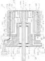
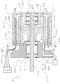
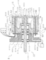
- FIG. 1 is a schematic diagram showing a cross-sectional view of a coreless rotary electric machine including a stator including a cylindrical coil according to an embodiment of the present invention.
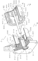
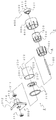
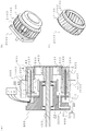
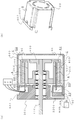
- FIG. 2 is a perspective view in which a part of the ironless rotary electric machine shown in FIG. 1 is cut away. It is a schematic diagram showing the disassembled perspective view of the member which comprises the lid type mount and cup type mount shown in FIG. It is a schematic diagram showing the perspective view of the inner side cylindrical air path formation body in which the clearance gap was provided in the circumferential direction and the magnet was arrange
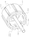
- FIG. 2 is a schematic diagram illustrating a cross-sectional view (a) and a perspective view (b) and (c) of a coreless rotary electric machine in which a multiblade centrifugal blower rotating body is fitted and fixed to the outer cylindrical air passage forming body shown in FIG. 1.
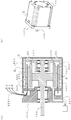
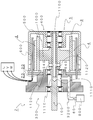
- FIG. 8 It is a schematic diagram showing as a cross-sectional view an ironless rotary electric machine including a stator including a cylindrical coil according to another embodiment of the present invention. It is a schematic diagram showing the disassembled perspective view of the member which comprises the lid type mount shown in FIG. 8, an intermediate
- FIG. 12 It is a schematic diagram showing as a cross-sectional view an ironless rotary electric machine including a stator including a cylindrical coil, which is still another embodiment of the present invention. It is a schematic diagram showing the disassembled perspective view of the member which comprises the lid type mount shown in FIG. 12, an intermediate
- FIG. 13 is a schematic diagram showing a cross-sectional view (a) and a perspective view (b) of a coreless rotary electric machine in which a multiblade centrifugal air blowing rotor is fitted and fixed to the outer cylindrical air passage forming body shown in FIG. 12.
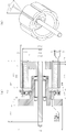
- It is a schematic diagram of the drive test based on one embodiment of a coreless rotating electrical machine. Sectional drawing (a) and perspective view (b) of the rotating electrical machine to be measured shown in FIG. 16 are shown.
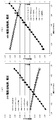
- the drive voltage is set to 24V and 48V, the load torque (N ⁇ m) is changed, and the change in the rotational speed (rpm) and the amount of current (A) is formed inside the cylindrical coil of the rotating electric machine to be measured.
- the cooling air In the case where the cooling air is not first supplied to the second air gap, the cooling air of 1 atm and 20 ° C. is supplied in the second air at 30 liters (stp) / min. And thirdly, it is a comparative diagram in which the case of supplying cooling air of 144 liters (stp) / min is measured.
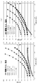
- the drive voltage is set to 24 V and 48 V, the load torque (N ⁇ m) is changed, and the change in the output (W) and temperature (° C.) caused thereby is the first formed inside the cylindrical coil of the electric motor to be measured.
- the cooling air In the case where the cooling air is not supplied to the two gaps, the cooling air of 1 atm / 20 ° C.
- FIG. 3 is a comparative diagram in which the case where 144 liters (stp) / min of cooling air is supplied is measured.
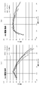
- the drive voltage is set to 24 V and 48 V, the load torque (N ⁇ m) is changed, and the change in efficiency ⁇ (%) is caused in the second gap formed inside the cylindrical coil of the electric motor to be measured.
- cooling air when cooling air is not supplied, secondly when cooling air of 1 atm and 20 ° C. is supplied with cooling air of 30 liters (stp) / min, and thirdly 144 liters It is the comparison figure which each measured the case where the cooling air is supplied (stp) / min.
- the power supply voltage V (V) is the product of the current I (A) flowing through the armature coil and the resistance R ( ⁇ ) of the armature coil, and the counter electromotive force E 0 ( It is balanced with the sum of V).
- T Kt ⁇ I (1)
- P T ⁇ ⁇ (2)
- V IR + E 0 (3)
- the electric motor of the present invention provided with a stator including the cylindrical coil shown in FIGS.
- the feature of the structure is that, first, a cylindrical coil formed by a laminated structure of conductive metal sheets is used as the energizable coil body constituting the fixed armature.
- a coil body and a manufacturing method thereof for example, as a coil body and a manufacturing method thereof, a plurality of conductive metal sheets via a plurality of linear portions spaced apart in the longitudinal direction and an insulating layer are used.
- the laminate structure is preferably molded with a certain rigidity of 5 mm or less.
- the second basic feature is that one end surface of the cylindrical coil is closed by the inner peripheral surface of the stator 2, and the other open end surface of the cylindrical coil constitutes the rotor 3, for example, Outer and inner cylindrical air passage forming bodies made of a magnetic body provided with permanent magnets 4 (in one embodiment, the outer cylindrical air passage forming body is hereinafter referred to as “outer yoke”, and the inner cylindrical air passage forming body is referred to as “ In this case, the structure is inserted into the first gap, that is, the air gap 40 in which a magnetic field having a donut cross section is formed.
- the cylindrical coil inserted and arranged in the air gap 40 has its inner and outer peripheral surfaces not in contact with the inner peripheral surface of the outer yoke of the rotor 3 and the outer peripheral surface of the inner yoke, and has an open end surface.
- the air gap 40 floats in a slight gap so as not to contact the inner surface of the rotor 3. It has a structure in which the stator 2 and the rotor 3 are arranged on the drive shaft so that the cylindrical coil is arranged in this way.
- the third feature of the basic structure is that it has a structure in which the second gap 20 and the third gap 30 are formed by the stator 2, the cylindrical coil and the rotor 3. More specifically, the second air gap 20 is formed between the open end surface of the outer yoke and the inner yoke integrated with the rotor 3 and the inner surface of the stator 2 facing the end surface. Is formed on the inner peripheral surface of the cylindrical coil closed by the air gap, and the air gap communicates with the air gap 40.
- the third gap 30 is formed between the air gap 40 and the outside air on the outer peripheral surface of the cylindrical coil closed by the inner surface of the stator 2.
- the electric motor of the present invention has a structure in which at least the second gap 20 is communicated with the outside air by the open end of the outer yoke via the third gap 30. Therefore, a negative pressure state is generated in the second gap 20 due to the pressure difference around the rotor generated by the rotational torque of the rotor 3.
- outside air is taken in here or refrigerant or cooling air is sent in
- the outside air sucked in or the refrigerant or cooling air that is sucked in passes through the air gap 40 in which a magnetic field is formed. It is discharged from the open end of the outer yoke via the third gap 30 while tracing the surface and the outer peripheral surface.
- the electric motor of the present invention has an image that the higher the rotation speed of the rotor 3, that is, the greater the output W, the greater the pressure difference around the rotor 3, thus increasing the cooling effect. It has periodical technical characteristics.
- This is derived from the basic structure of the electric motor of the present invention described above. That is, it is a coreless coil that does not have an iron loss that increases as the number of revolutions increases in a narrow air gap 40 with a large magnetic flux density, and has a rigidity formed by a laminate of ultrathin metal sheets having a thickness of 5 mm or less.
- This is derived from the feature of an electric motor having a basic structure in which the cylindrical coil is inserted and arranged in a floating state, and the second gap 20 in the closed space communicates only with the open end of the outer yoke.
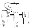
- FIG. 16 is a schematic diagram of a driving experiment based on an embodiment (prototype motor) of a coreless rotary electric machine including a stator including the cylindrical coil shown in FIG.
- this drive experiment is performed by attaching a generator (m-link CP8048) to the output shaft of the motor via a torque meter (UNIPULSE TM301).
- the output power derived from the load torque and rotation speed generated by consuming the combined power generated by the generator (three-phase PWM drive power supply: ICAN / TEC BLD750) with an external variable resistor and the input to the motor
- the efficiency of the motor is obtained by measuring the electric power.
- the input power to the motor was measured by inserting a wattmeter (HIOKI PW33369) between the motor drive power supply and the motor because of the voltage and current supplied from the drive power supply and the power factor of the drive state.
- the measurement procedure started from driving the motor at a constant voltage V (V) from an approximate no-load state where the generator load was almost zero.
- the load torque of the motor is increased by sequentially changing the generator external resistance, and the current I (A), input power Pi (W), output power Po (W), torque T (N ⁇ m), and rotational speed N are appropriately selected. (Rpm) was recorded, and the ratio of output power to input power (Po / Pi), that is, efficiency ⁇ was determined.
- FIG. 17 An outline of the cross-sectional view (a) and perspective view (b) of the electric motor to be measured shown in FIG. 17 is as follows. First, a cylindrical coil having a thickness of 1.35 mm and an outer diameter of 51 mm has a width of 11 mm and a longitudinal direction. The air gap 40 is inserted into the first gap having a length of 37.75 mm.
- the magnet 4 is an outer peripheral surface of an inner yoke with an 8-pole neodymium magnet made of a rectangular parallelepiped having a thickness of 3.85 mm spaced apart by 1.19 mm in the longitudinal direction. Deployed.
- the second and third gaps having a width of 2.33 mm are provided between the open end faces of the outer yoke and the inner yoke integrated with the rotor 3 and the inner face of the stator 2 facing the end faces.
- a path having an inner diameter of 3 mm that communicates with the outside is provided in order to send cooling air.
- the gap between the inner peripheral surface of the cylindrical coil and the outer peripheral surface of the neodymium magnet 4 is only 0.3 mm, and the outer peripheral surface of the cylindrical coil and the outer yoke The gap with the inner peripheral surface is only 0.4 mm. All the gaps are narrow, and their technical features will be described later.
- the driving voltage is set to 24 V and 48 V by the driving power source, and the load torque (N ⁇ m) is set to 0.1 (N ⁇ m) in the approximate unloaded state of the generator by the variable load of the generator.
- ⁇ 1> an inner diameter of 3 mm that communicates with the outside.
- ⁇ 2> When the path is closed and cooling air is not supplied, ⁇ 2> When the path is opened and cooling air at 1 atm and 20 ° C. is supplied with cooling air of 30 liters (stp) / min, and ⁇ 3> Similarly, the case where the path was opened and cooling air of 144 liters (stp) / min was supplied was measured.
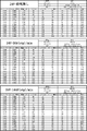
- FIG. 22 is a comparison diagram based on the measured values.
- the amount of air supplied to the second gap shown here is the amount of air forcedly fed by the compressor, that is, the amount of air sent by 50 kPa in the case of ⁇ 2>, 20 liters (op) / min, In the case of ⁇ 3>, it is a numerical value obtained by converting each of the amount of air 40 liters (op) / min sent by 265 kPa into 1 atm and 20 ° C.
- the current is 10.2A to 10.7A in the case of ⁇ 1> to ⁇ 3>, which is not much different when compared with the setting of 24V.
- the number of revolutions when it was set to 24V, it was 2700-2800 rpm, but when it was switched to 48V, it was less than 6900 rpm in any of ⁇ 1> to ⁇ 3> and was set to 24V. However, there is no significant difference between ⁇ 1> and ⁇ 3>.
- the current (A) increases linearly as the load torque (N ⁇ m) increases, even when the drive voltage is changed and the condition is changed from ⁇ 1> to ⁇ 3> (see above). 1) It was confirmed that the formula was established.
- FIG. 19 and FIG. 20 compare the measured values of ⁇ 1> to ⁇ 3> after setting the voltages to 24 V and 48 V, respectively.
- An electric motor is a device that converts electric power into motive power, that is, for converting electric energy into mechanical energy.
- the generator converts power into electric power and there is no structural difference between the two
- the present invention is directed to the electric motor and the generator.
- various losses occur and turn into heat.
- the loss of a general rotating electrical machine is classified into (i) copper loss, (ii) iron loss (hysteresis loss + eddy current loss), and (iii) mechanical loss.
- copper loss and (ii) iron loss account for a large proportion of the loss.
- the electric motor of the present invention constituted by the stator 2 including the cylindrical coil and the rotor 3 including the air gap 40 in which the cylindrical coil is inserted and disposed, since it is ironless (ii), no iron loss occurs. An eddy current loss occurs in the coil, which also becomes a cause of heat generation of the coil together with (i) copper loss. Therefore, the first technical problem of the present invention is to control the heat generation of the cylindrical coil, and the second technical problem is a rectangular parallelepiped arranged on the outer peripheral surface of the inner yoke in the longitudinal direction of the air gap 40. This is to suppress the heating of the magnet so that the magnet does not deteriorate the coercive force by heating.
- Non-patent Document 1 a neodymium magnet mainly composed of rare earth neodymium and iron and boron has a very strong magnetic force but has a large demagnetizing effect due to heat, and the use limit is about 80 ° C.
- the permanent magnet used in this driving experiment is a neodymium magnet, it uses a heat-resistant type and can be used up to 120 ° C.
- the magnet 4 used in the electric motor of the present invention is more preferably a heat-resistant neodymium magnet.
- the load torque when the drive voltage is 24 V can be increased to 0.85 N ⁇ m where the average surface temperature of the cylindrical coil exceeds 80 ° C.
- the output was 203 W.
- the load torque at which the average surface temperature of the cylindrical coil exceeds 80 ° C. in the case of ⁇ 2> is 0.75 N ⁇ m, and the output at that time is 519 W.
- the size of the output As one of the scales to see the performance of the electric motor, it can be evaluated by the size of the output. Incidentally, when the drive voltage is set to 48V, ⁇ 1> the load torque is 0.55 N ⁇ m and the output is 410 W when the temperature of the cylindrical coil is 80 ° C. without cooling air supply. On the other hand, the load torque when ⁇ 2> cooling air supply 30 liters (stp) / min and the temperature of the cylindrical coil is 80 ° C. is 0.75 N ⁇ m (1.36 times ⁇ 1>), The output is 519 W (1.27 times ⁇ 1>).
- FIG. 20 shows changes in efficiency ⁇ in the cases ⁇ 1> to ⁇ 3> when the drive voltage is set to 24V and when the drive voltage is switched to 48V.
- the desired efficiency ⁇ for an electric motor is 80% or more
- the load torque when the efficiency ⁇ exceeds 80% is about 0.40 to 0.50 N ⁇ m
- the output is about 137 to 153 W
- the electric motor There is no big difference in performance.
- the efficiency ⁇ as the electric motor is equal to or higher than the above even if the cooling coil is supplied and the cylindrical coil is cooled as in ⁇ 2> and ⁇ 3>.
- the load torque is less than 80%.
- the efficiency ⁇ falls below 80% in the case of ⁇ 2> when the load torque is 0.80 N ⁇ m and the output is 537 W, and in the case of ⁇ 3> Is when the load torque is 0.90 N ⁇ m and the output is 592 W.
- the average surface temperature of the cylindrical coil at that time is 88 ° C. in the case of ⁇ 2>, maintained at 71 ° C. in the case of ⁇ 3>, and does not reach 80 ° C.
- the characteristics of the electric motor of the present invention can be made clearer by performing the same performance test as this time while sequentially increasing the drive voltage, for example, 24V, 36V, 48V, and 60V. That is easily estimated from the results of this driving experiment.
- the drive voltage for example, 24V, 36V, 48V, and 60V.
- FIG. 1 not only is a path 3200 communicating with the outside air provided in the lid-type mount 300 that constitutes the stator 2, but also the rotor-type 3 is connected to the cup-type mount 400 of the rotor 3 via the filter 431.
- FIG. 4 shows the fourth basic structure of the electric motor of the present invention.
- a rectangular parallelepiped neodymium magnet fixed to the surface of the inner yoke along the longitudinal direction of the drive shaft. Are deployed with a slight spacing, for example 1.19 mm.
- the interval of 1.19 mm corresponds to the interval 401 of each magnet 4, and when the refrigerant or cooling air 80 supplied to the second gap 20 passes through the air gap 40 of the first gap, the refrigerant or cooling air is supplied. It has a blade effect as a blade body that increases the flow rate of 80 and enhances the cooling effect, that is, the effect of increasing the suction force.
- FIG. 5 to 7 show further improvements based on the basic structure of the electric motor of the present invention. That is, in FIG. 5, as apparent from the perspective view (b), the exterior body 9 having the protective jacket 900 is attached to the electric motor of the present invention shown in FIG. It is a thing.
- FIG. 6 shows that a part of the drive shaft 100 of the electric motor of the present invention shown in FIG. 1 is formed into a hollow body 1100, and the refrigerant or cooling air 80 passes through the hollow body 1100 into the second space 20 in the closed space. And the entire inside of the electric motor closed by the cylindrical coil 200 is cooled.
- FIG. 7 shows the inner exhaust hole 560 and the outer exhaust at positions corresponding to the intervals 401 of the magnets 4 provided in the inner yoke 500 and the outer yoke 600 of the ironless rotary electric machine shown in FIGS.
- a multi-blade centrifugal air rotating body 2000 that cooperates with the hole 660 to enhance the cooling effect on the cylindrical coil 200 and the magnet 4 is fitted and fixed.
- the cooling method of the electric motor As for the cooling method of the electric motor according to the second aspect of the present invention, it operates the rotor 3 by energizing the cylindrical coil 200, and sends or draws the refrigerant or cooling air 80 into the second gap 20.
- the refrigerant or cooling air 80 directly cools the inner peripheral surface and the outer peripheral surface of the cylindrical coil 200, and includes each step of discharging the refrigerant or cooling air 80 that has circulated through the first gap 40 from the electric motor.
- FIG. 1 it is provided with a path 3200 in the lid mount 300 that leads to the second gap 20 located on the inner peripheral side 210 of the cylindrical coil 200, and refrigerant or cooling air 80 is supplied from the path 3200.
- the step of feeding or pulling into the second gap 20 and / or the rotation of the vent 430 for taking outside air into the space 540 leading to the second gap 20 on the inner peripheral side of the inner yoke 500 and the filter 431 covering the vent 430 are rotated.
- the method may further include the step of causing 40 to suck.
- dust and the like are less likely to adhere to the filter 431, so that the internal cooling of the electric motor can be further increased.
- the cup-type mount 400 has a gap 401 along the longitudinal direction of the cylindrical coil 200. Further, an inner exhaust hole 560 and / or an outer exhaust hole 660 is provided at the position of the outer yoke 600 at the position of the inner yoke 500 corresponding to the gap 401 of the magnet 4, and the rotation generated by the rotational torque of the rotor 3.
- the cooling effect of the refrigerant or the cooling air 80 is further included by discharging the refrigerant or the cooling air 80 sent into the first gap 40 from the third gap 30 and the outer exhaust hole 660 due to the pressure difference around the child 3. Can also be increased.
- It is also composed of two discs 2100 having a width corresponding to the third gap 30 and the outer exhaust hole 660 and a plurality of vanes 2200 suspended from the two discs 2100 facing the axis of the disc 2100.
- a step of further amplifying the pressure difference around the rotor 3 can be included, and the circulation of the refrigerant or the cooling air 80 in the first gap 40 can be further accelerated.
- the electric motor according to the third and fourth aspects of the present invention will be described with reference to FIGS. 8 to 11.
- the structure of the lid-type mount 300 constituting the stator 2 will be described. Is the same as that of the electric motor of the first aspect.
- the rotor 3 is configured such that an intermediate mount 1000 including an inner yoke 500 having a magnet 4 disposed on the outer peripheral surface thereof is fixedly connected to the drive shaft 100.
- the cup-type mount 400 including the outer yoke 600 that forms the first gap, that is, the air gap 40 with the inner yoke 500 and closes the magnetic path is rotatably connected to the drive shaft that penetrates the intermediate mount 1000. That is, the second rotor is used.
- the rotor 3 is first rotated when starting up by energizing the cylindrical coil 200.
- the 2nd rotor 5 cooperates with the rotor 3 and forms a magnetic field, it follows rotation of the rotor 3 and starts rotation late.
- the rotor 3 and the second rotor 5 rotate in synchronization. Therefore, in this electric motor, since the rise or stop of the rotation of the rotor 3 is configured separately from the outer yoke 600 as compared with the electric motor of the first aspect, the inertial force at the time of starting or stopping, that is, Inertia has the technical feature of being small.
- the cup-type mount 400 constituting the second rotor 5 cannot be provided with the vent 430 for taking outside air into the space 540 that leads to the second gap 20 on the inner peripheral side of the inner yoke 500.
- the refrigerant or the cooling air 80 is sent or drawn into the second gap 20 from the path 3200 provided in the stator 2, and the rotor 3 and the second
- the refrigerant or cooling air 80 directly cools the inner peripheral surface and the outer peripheral surface of the cylindrical coil 200 due to the pressure difference around the rotor 3 generated by the rotational torque of the rotor 5.
- Each step of discharging the cooling air 80 from the electric motor is included. Thereby, the inside of this electric motor can be cooled similarly to the electric motor of the 2nd mode.
- the rotor 3 has a cup-type mount 400 including an outer yoke 600 in which a magnet 4 is arranged on the inner peripheral surface fixedly connected to the drive shaft 100. 3 and the outer yoke 600 form a first gap, that is, an air gap 40, and an intermediate mount 1000 including an inner yoke 500 acting to close the magnetic path is provided between the stator 2 and the rotor 3.
- the second rotor 5 is rotatably connected to the second rotor 5.
- the rotor 3 is first rotated when starting up by energizing the cylindrical coil 200.
- the 2nd rotor 5 cooperates with the rotor 3 and forms a magnetic field, it follows rotation of the rotor 3 and starts rotation late.
- the rotor 3 and the second rotor 5 rotate in synchronization. Therefore, in the present electric motor, the rise or stop of the rotation of the rotor 3 is configured separately from the inner yoke 500 as compared with the electric motor of the first aspect. Inertia has the technical feature of being small. However, as is apparent from FIG. 12, it is not necessary to provide a space 540 leading to the second gap 20 on the inner peripheral side of the inner yoke 500 fixed to the intermediate mount 1000 that constitutes the second rotor 5.
- the magnet 4 is arranged so as to be bonded and fixed to the inner peripheral surface of the outer yoke 600 constituting the rotor 3. There is no fear that the magnet 4 is peeled off by the centrifugal force caused by the rotation. Further, the magnet 4 is disposed in the longitudinal direction via the gap 401, and an exhaust hole 660 is further provided at the position of the outer yoke 600 corresponding to the gap 401, and the outer yoke is provided so as to correspond to the third gap 30 and the exhaust hole 660.
- the multiblade centrifugal blower rotator 2000 can be fitted and fixed to 600 so that the refrigerant or the cooling air 80 can be more efficiently distributed in the first gap 40 and the cooling effect of the electric motor can be enhanced.
- the refrigerant or the cooling air 80 is sent or drawn into the second gap 20 from the path 3200 provided in the stator 2, and the rotor 3
- the refrigerant or cooling air 80 directly cools the inner peripheral surface and the outer peripheral surface of the cylindrical coil 200 by the pressure difference around the rotor 3 or the rotor 5 generated by the rotational torque of the second rotor 5, and the first
- Each step includes discharging the refrigerant or cooling air 80 flowing through the gap 40 from the electric motor. Thereby, the inside of this electric motor can be cooled similarly to the electric motor of the 2nd aspect or the 4th aspect.
- cylindrical coil 200 having a very thin mechanical strength composed of a laminated structure of conductive metal sheets.
- the cylindrical coil 200 is fixed so that one end face is closed to the inner surface of the stator, and the other open end face is inserted in a state of being floated in a narrow air gap 40, whereby a cylindrical coil 200 is applied to a magnetic field having a high magnetic flux density.
- 200 main bodies can be positioned.
Landscapes
- Engineering & Computer Science (AREA)
- Power Engineering (AREA)
- Motor Or Generator Cooling System (AREA)
- Permanent Magnet Type Synchronous Machine (AREA)
- Windings For Motors And Generators (AREA)
- Iron Core Of Rotating Electric Machines (AREA)
Abstract
Priority Applications (6)
| Application Number | Priority Date | Filing Date | Title |
|---|---|---|---|
| DE112015004041.2T DE112015004041T5 (de) | 2014-09-04 | 2015-03-04 | Kernlose drehende elektrische maschine mit einem ständer, der eine zylindrische spule enthält, sowie kühlverfahren dafür |
| KR1020177007599A KR101996320B1 (ko) | 2014-09-04 | 2015-03-04 | 원통 코일을 포함한 고정자를 갖춘 무철심 회전 전기 기계 및 그 냉각 방법 |
| US15/508,633 US10651702B2 (en) | 2014-09-04 | 2015-03-04 | Coreless rotating electrical machine with stator including cylindrical coil and cooling method therefor |
| JP2015551643A JP5943333B1 (ja) | 2014-09-04 | 2015-03-04 | 円筒コイルを備えた固定子を含む無鉄心回転電気機械およびその冷却方法 |
| CN201580047697.0A CN106716793B (zh) | 2014-09-04 | 2015-03-04 | 具备包含圆筒线圈的定子的无铁心旋转电力机构及其冷却方法 |
| US16/031,247 US10637319B2 (en) | 2014-09-04 | 2018-07-10 | Coreless rotating electrical machine with stator including cylindrical coil and cooling method therefor |
Applications Claiming Priority (2)
| Application Number | Priority Date | Filing Date | Title |
|---|---|---|---|
| JP2014180294 | 2014-09-04 | ||
| JP2014-180294 | 2014-09-04 |
Related Child Applications (2)
| Application Number | Title | Priority Date | Filing Date |
|---|---|---|---|
| US15/508,633 A-371-Of-International US10651702B2 (en) | 2014-09-04 | 2015-03-04 | Coreless rotating electrical machine with stator including cylindrical coil and cooling method therefor |
| US16/031,247 Continuation US10637319B2 (en) | 2014-09-04 | 2018-07-10 | Coreless rotating electrical machine with stator including cylindrical coil and cooling method therefor |
Publications (1)
| Publication Number | Publication Date |
|---|---|
| WO2016035358A1 true WO2016035358A1 (fr) | 2016-03-10 |
Family
ID=55439433
Family Applications (1)
| Application Number | Title | Priority Date | Filing Date |
|---|---|---|---|
| PCT/JP2015/056310 WO2016035358A1 (fr) | 2014-09-04 | 2015-03-04 | Machine électrique tournante sans noyau à stator comprenant une bobine cylindrique et procédé de refroidissement associé |
Country Status (6)
| Country | Link |
|---|---|
| US (2) | US10651702B2 (fr) |
| JP (2) | JP5943333B1 (fr) |
| KR (1) | KR101996320B1 (fr) |
| CN (1) | CN106716793B (fr) |
| DE (1) | DE112015004041T5 (fr) |
| WO (1) | WO2016035358A1 (fr) |
Cited By (17)
| Publication number | Priority date | Publication date | Assignee | Title |
|---|---|---|---|---|
| JP2016154440A (ja) * | 2014-09-04 | 2016-08-25 | 株式会社エムリンク | 円筒コイルを含む固定子を備えた無鉄心回転電気機械およびその冷却方法 |
| JP6005886B1 (ja) * | 2016-03-03 | 2016-10-12 | 株式会社エムリンク | 円筒コイルを備えた固定子を含む無鉄心回転電気機械およびその冷却方法 |
| US20180048195A1 (en) * | 2016-08-10 | 2018-02-15 | Chin-Hsing Feng | Electric motor |
| WO2018096636A1 (fr) * | 2016-11-24 | 2018-05-31 | 株式会社エムリンク | Machine électrique rotative sans noyau destinée à fonctionner sous une charge dépassant la valeur nominale, son procédé de commande et système de commande la comprenant |
| JP2018085918A (ja) * | 2017-11-14 | 2018-05-31 | 株式会社エムリンク | 定格を超える負荷で稼働するための無鉄心回転電気機械、その駆動方法、および、それを含む駆動システム |
| JP2018148599A (ja) * | 2017-03-01 | 2018-09-20 | ミネベアミツミ株式会社 | モータ |
| CN108667198A (zh) * | 2017-03-27 | 2018-10-16 | M-链接株式会社 | 冷却辅助件和无芯无刷电机 |
| WO2018219620A1 (fr) * | 2017-06-02 | 2018-12-06 | Valeo Systèmes d'Essuyage | Moto-reducteur pour systeme d'essuyage de vehicule automobile |
| WO2019017496A1 (fr) * | 2017-07-21 | 2019-01-24 | 株式会社デンソー | Machine électrique tournante |
| JP2019106864A (ja) * | 2017-07-21 | 2019-06-27 | 株式会社デンソー | 回転電機 |
| WO2019131911A1 (fr) * | 2017-12-28 | 2019-07-04 | 株式会社デンソー | Machine électrique rotative |
| US20190222085A1 (en) * | 2018-01-12 | 2019-07-18 | Carrier Corporation | Dual rotor, coreless, electromagnetic machine |
| JP2019122229A (ja) * | 2017-12-28 | 2019-07-22 | 株式会社デンソー | 回転電機 |
| JP2020108280A (ja) * | 2018-12-27 | 2020-07-09 | 株式会社デンソー | 回転電機 |
| EP3840180A1 (fr) * | 2019-12-19 | 2021-06-23 | Black & Decker Inc. | Moteur sans balais à rotor extérieur noyé pour un outil électrique |
| US11437900B2 (en) | 2019-12-19 | 2022-09-06 | Black & Decker Inc. | Modular outer-rotor brushless motor for a power tool |
| KR20230158437A (ko) * | 2020-06-01 | 2023-11-20 | 오원섭 | 코깅리스 코어리스 bldc 모터 |
Families Citing this family (21)
| Publication number | Priority date | Publication date | Assignee | Title |
|---|---|---|---|---|
| CN106877539B (zh) * | 2017-04-16 | 2018-10-26 | 朱幕松 | 无铁芯无刷无齿大轮毂电机 |
| US11843334B2 (en) | 2017-07-13 | 2023-12-12 | Denso Corporation | Rotating electrical machine |
| JP6939543B2 (ja) | 2017-07-21 | 2021-09-22 | 株式会社デンソー | 回転電機 |
| CN113972807B (zh) | 2017-07-21 | 2023-10-27 | 株式会社电装 | 旋转电机 |
| DE112018006694T5 (de) | 2017-12-28 | 2020-09-10 | Denso Corporation | Rotierende elektrische Maschine |
| CN111566904B (zh) | 2017-12-28 | 2023-04-28 | 株式会社电装 | 旋转电机 |
| CN111565965B (zh) | 2017-12-28 | 2023-07-14 | 株式会社电装 | 车轮驱动装置 |
| DE112018006699T5 (de) | 2017-12-28 | 2020-09-10 | Denso Corporation | Rotierende elektrische Maschine |
| JP6939750B2 (ja) | 2017-12-28 | 2021-09-22 | 株式会社デンソー | 回転電機 |
| JP6927186B2 (ja) | 2017-12-28 | 2021-08-25 | 株式会社デンソー | 回転電機 |
| JP6922868B2 (ja) | 2017-12-28 | 2021-08-18 | 株式会社デンソー | 回転電機システム |
| WO2020022366A1 (fr) * | 2018-07-25 | 2020-01-30 | 株式会社デンソー | Machine dynamo-électrique et roue utilisant ladite machine dynamo-électrique |
| JP7255383B2 (ja) * | 2018-07-25 | 2023-04-11 | 株式会社デンソー | 回転電機 |
| DE102019200098A1 (de) | 2019-01-07 | 2020-07-09 | Audi Ag | Fluidgekühlter Rotor für eine elektrische Maschine |
| US11128197B2 (en) * | 2019-09-20 | 2021-09-21 | Hts Llc | Linear electric device having reciprocating movement linked to rotational movement of a shaped cam |
| DE102019126980B4 (de) | 2019-10-08 | 2022-10-20 | Hirschvogel Umformtechnik Gmbh | Elektrische Maschine |
| CN110649731A (zh) * | 2019-10-26 | 2020-01-03 | 山东华盛农业药械有限责任公司 | 柱式无铁芯电机 |
| WO2021176668A1 (fr) | 2020-03-05 | 2021-09-10 | 株式会社デンソー | Machine tournante électrique |
| EP3993228A1 (fr) * | 2020-10-27 | 2022-05-04 | BSH Hausgeräte GmbH | Noyau de rotor, rotor à aimant permanent, moteur électrique et pompe électrique pour un appareil ménager |
| DE102022209762A1 (de) | 2022-09-16 | 2024-03-21 | Rolls-Royce Deutschland Ltd & Co Kg | Elektrische Maschine mit offener Spulenwicklung zur Direktkühlung |
| CN116505686B (zh) * | 2023-06-26 | 2023-09-26 | 中山格智美电器有限公司 | 一种提升外转子无刷电机散热性能的转子结构及电机 |
Citations (9)
| Publication number | Priority date | Publication date | Assignee | Title |
|---|---|---|---|---|
| JPS62189954A (ja) * | 1985-12-23 | 1987-08-19 | ユニ−ク、モビリテイ−、インコ−ポレ−テツド | 電磁変換器 |
| JPS62268335A (ja) * | 1986-05-14 | 1987-11-20 | Toshiba Corp | 車輌用回転電機 |
| JPH0580159U (ja) * | 1992-03-31 | 1993-10-29 | 神鋼電機株式会社 | アウターロータ形高速回転電機における冷却構造 |
| JPH05344680A (ja) * | 1992-06-05 | 1993-12-24 | Toshiba Toransupooto Eng Kk | 車両用アウターロータ電動機 |
| JPH0837769A (ja) * | 1994-04-26 | 1996-02-06 | Orto Holding Ag | 電気的整流が施された直流機 |
| JPH09168246A (ja) * | 1995-12-13 | 1997-06-24 | Fuji Electric Co Ltd | 永久磁石同期機の冷却装置 |
| JP2004538744A (ja) * | 2001-05-16 | 2004-12-24 | ジー アンド ジー テクノロジー,インコーポレイティド | ブラシレス・モータ |
| JP2010166717A (ja) * | 2009-01-16 | 2010-07-29 | Nissan Motor Co Ltd | 多層モータの冷却構造 |
| JP2012016218A (ja) * | 2010-07-02 | 2012-01-19 | Shicoh Engineering Co Ltd | ホイールインモータ及び電動車両 |
Family Cites Families (19)
| Publication number | Priority date | Publication date | Assignee | Title |
|---|---|---|---|---|
| JPS494056A (fr) | 1972-05-03 | 1974-01-14 | ||
| US4562367A (en) * | 1982-06-30 | 1985-12-31 | Mitsubishi Denki Kabushiki Kaisha | Low inertia, speed variable induction motor |
| US5319844A (en) | 1985-12-23 | 1994-06-14 | Unique Mobility, Inc. | Method of making an electromagnetic transducer |
| JPH0522133A (ja) | 1991-07-17 | 1993-01-29 | Hitachi Ltd | Ad変換器およびアナログ・デイジタル混在ic |
| JP2517970Y2 (ja) | 1991-09-06 | 1996-11-20 | 株式会社四国総合研究所 | 電気自動車用電動機の冷却構造 |
| JP2571302Y2 (ja) * | 1992-07-20 | 1998-05-18 | 株式会社安川電機 | 高速回転電機の冷却装置 |
| JP2657192B2 (ja) | 1992-11-17 | 1997-09-24 | セイコープレシジョン株式会社 | リニア直流ブラシレスモータ |
| JP3494056B2 (ja) | 1999-01-25 | 2004-02-03 | 国産電機株式会社 | アウターロータ型磁石発電機 |
| US6111329A (en) | 1999-03-29 | 2000-08-29 | Graham; Gregory S. | Armature for an electromotive device |
| JP4728639B2 (ja) * | 2004-12-27 | 2011-07-20 | 株式会社デンソー | 電動車輪 |
| JP2006246678A (ja) | 2005-03-07 | 2006-09-14 | Toyota Motor Corp | アウターロータ型のホイールインモータおよび電気自動車およびハイブリット自動車 |
| KR100677281B1 (ko) * | 2005-06-16 | 2007-02-02 | 엘지전자 주식회사 | 토로이달 권선 방식을 적용한 하이브리드 유도전동기 |
| US8820448B2 (en) * | 2010-07-02 | 2014-09-02 | M-Link Co., Ltd. | In-wheel motor and electrically driven vehicle |
| US9150093B2 (en) * | 2010-07-02 | 2015-10-06 | M-Link Co., Ltd. | In-wheel motor and electrically driven vehicle |
| CN202167957U (zh) * | 2011-03-25 | 2012-03-14 | 安鲁荣 | 低转速多转子发电机 |
| JP5702748B2 (ja) * | 2012-03-07 | 2015-04-15 | 本田技研工業株式会社 | 電動車両高電圧機器冷却システムおよび電動車両高電圧機器の冷却方法 |
| CN102946181A (zh) * | 2012-11-26 | 2013-02-27 | 王九龙 | 一种新型电机 |
| JP5943333B1 (ja) * | 2014-09-04 | 2016-07-05 | 株式会社エムリンク | 円筒コイルを備えた固定子を含む無鉄心回転電気機械およびその冷却方法 |
| JP6005886B1 (ja) * | 2016-03-03 | 2016-10-12 | 株式会社エムリンク | 円筒コイルを備えた固定子を含む無鉄心回転電気機械およびその冷却方法 |
-
2015
- 2015-03-04 JP JP2015551643A patent/JP5943333B1/ja active Active
- 2015-03-04 WO PCT/JP2015/056310 patent/WO2016035358A1/fr active Application Filing
- 2015-03-04 KR KR1020177007599A patent/KR101996320B1/ko active IP Right Grant
- 2015-03-04 DE DE112015004041.2T patent/DE112015004041T5/de not_active Withdrawn
- 2015-03-04 US US15/508,633 patent/US10651702B2/en active Active
- 2015-03-04 CN CN201580047697.0A patent/CN106716793B/zh active Active
-
2016
- 2016-03-25 JP JP2016061769A patent/JP6198085B2/ja active Active
-
2018
- 2018-07-10 US US16/031,247 patent/US10637319B2/en active Active
Patent Citations (9)
| Publication number | Priority date | Publication date | Assignee | Title |
|---|---|---|---|---|
| JPS62189954A (ja) * | 1985-12-23 | 1987-08-19 | ユニ−ク、モビリテイ−、インコ−ポレ−テツド | 電磁変換器 |
| JPS62268335A (ja) * | 1986-05-14 | 1987-11-20 | Toshiba Corp | 車輌用回転電機 |
| JPH0580159U (ja) * | 1992-03-31 | 1993-10-29 | 神鋼電機株式会社 | アウターロータ形高速回転電機における冷却構造 |
| JPH05344680A (ja) * | 1992-06-05 | 1993-12-24 | Toshiba Toransupooto Eng Kk | 車両用アウターロータ電動機 |
| JPH0837769A (ja) * | 1994-04-26 | 1996-02-06 | Orto Holding Ag | 電気的整流が施された直流機 |
| JPH09168246A (ja) * | 1995-12-13 | 1997-06-24 | Fuji Electric Co Ltd | 永久磁石同期機の冷却装置 |
| JP2004538744A (ja) * | 2001-05-16 | 2004-12-24 | ジー アンド ジー テクノロジー,インコーポレイティド | ブラシレス・モータ |
| JP2010166717A (ja) * | 2009-01-16 | 2010-07-29 | Nissan Motor Co Ltd | 多層モータの冷却構造 |
| JP2012016218A (ja) * | 2010-07-02 | 2012-01-19 | Shicoh Engineering Co Ltd | ホイールインモータ及び電動車両 |
Cited By (43)
| Publication number | Priority date | Publication date | Assignee | Title |
|---|---|---|---|---|
| JP2016154440A (ja) * | 2014-09-04 | 2016-08-25 | 株式会社エムリンク | 円筒コイルを含む固定子を備えた無鉄心回転電気機械およびその冷却方法 |
| JP6005886B1 (ja) * | 2016-03-03 | 2016-10-12 | 株式会社エムリンク | 円筒コイルを備えた固定子を含む無鉄心回転電気機械およびその冷却方法 |
| US20180048195A1 (en) * | 2016-08-10 | 2018-02-15 | Chin-Hsing Feng | Electric motor |
| KR20190051073A (ko) * | 2016-11-24 | 2019-05-14 | 가부시키가이샤 앰링크 | 정격을 넘는 부하에서 가동하기 위한 무철심 회전 전기 기계, 그 구동 방법, 및, 그것을 포함한 구동 시스템 |
| WO2018096636A1 (fr) * | 2016-11-24 | 2018-05-31 | 株式会社エムリンク | Machine électrique rotative sans noyau destinée à fonctionner sous une charge dépassant la valeur nominale, son procédé de commande et système de commande la comprenant |
| JP6399721B1 (ja) * | 2016-11-24 | 2018-10-03 | 株式会社エムリンク | 定格を超える負荷で稼働するための無鉄心回転電気機械、その駆動方法、および、それを含む駆動システム |
| US11251683B2 (en) | 2016-11-24 | 2022-02-15 | M-Link Co., Ltd. | Coreless rotating electrical machine for being operated under load exceeding rating, driving method thereof, and driving system including thereof |
| TWI756863B (zh) * | 2016-11-24 | 2022-03-01 | 日商M鏈接股份有限公司 | 無鐵心旋轉電機 |
| TWI712252B (zh) * | 2016-11-24 | 2020-12-01 | 日商M鏈接股份有限公司 | 用於在超過額定的負載下進行運作的無鐵心旋轉電機、其之驅動方法、以及包含其之驅動系統 |
| KR102126444B1 (ko) * | 2016-11-24 | 2020-07-08 | 가부시키가이샤 앰링크 | 정격을 넘는 부하에서 가동하기 위한 무철심 회전 전기 기계, 그 구동 방법, 및, 그것을 포함한 구동 시스템 |
| CN110140282A (zh) * | 2016-11-24 | 2019-08-16 | M-链接株式会社 | 用于在超过额定的负载下工作的无铁芯旋转电机及其驱动方法、以及包含该无铁芯旋转电机的驱动系统 |
| US11563361B2 (en) | 2016-11-24 | 2023-01-24 | M-Link Co., Ltd. | Coreless rotating electrical machine for being operated under load exceeding rating, driving method thereof, and driving system including thereof |
| JP2018148599A (ja) * | 2017-03-01 | 2018-09-20 | ミネベアミツミ株式会社 | モータ |
| JP2021170933A (ja) * | 2017-03-01 | 2021-10-28 | ミネベアミツミ株式会社 | モータのロータおよびこれを備えたモータ |
| JP7560631B2 (ja) | 2017-03-01 | 2024-10-02 | ミネベアミツミ株式会社 | モータ |
| JP7351876B2 (ja) | 2017-03-01 | 2023-09-27 | ミネベアミツミ株式会社 | モータ |
| CN108667198A (zh) * | 2017-03-27 | 2018-10-16 | M-链接株式会社 | 冷却辅助件和无芯无刷电机 |
| JP2018164373A (ja) * | 2017-03-27 | 2018-10-18 | 株式会社エムリンク | 無鉄心の円筒コイルを備えた固定子を含むブラシレス回転電気機械の冷却補助具および冷却補助具が装着された無鉄心の円筒コイルを備えた固定子を含むブラシレス回転電気機械 |
| JP7210478B2 (ja) | 2017-06-02 | 2023-01-23 | ヴァレオ システム デシュヤージュ | 自動車両ワイピングシステム用ギアモータ |
| WO2018219620A1 (fr) * | 2017-06-02 | 2018-12-06 | Valeo Systèmes d'Essuyage | Moto-reducteur pour systeme d'essuyage de vehicule automobile |
| US11548475B2 (en) | 2017-06-02 | 2023-01-10 | Valeo Systèmes d'Essuyage | Gear motor for motor vehicle wiping system |
| FR3066968A1 (fr) * | 2017-06-02 | 2018-12-07 | Valeo Systemes D'essuyage | Moto-reducteur pour systeme d'essuyage de vehicule automobile |
| JP2020522224A (ja) * | 2017-06-02 | 2020-07-27 | ヴァレオ システム デシュヤージュValeo Systemes D’Essuyage | 自動車両ワイピングシステム用ギアモータ |
| JP2019106862A (ja) * | 2017-07-21 | 2019-06-27 | 株式会社デンソー | 回転電機 |
| WO2019017496A1 (fr) * | 2017-07-21 | 2019-01-24 | 株式会社デンソー | Machine électrique tournante |
| JP2019106864A (ja) * | 2017-07-21 | 2019-06-27 | 株式会社デンソー | 回転電機 |
| JP2019106867A (ja) * | 2017-07-21 | 2019-06-27 | 株式会社デンソー | 回転電機 |
| JP2019106866A (ja) * | 2017-07-21 | 2019-06-27 | 株式会社デンソー | 回転電機 |
| JP2019106865A (ja) * | 2017-07-21 | 2019-06-27 | 株式会社デンソー | 回転電機 |
| JP2019106863A (ja) * | 2017-07-21 | 2019-06-27 | 株式会社デンソー | 回転電機 |
| JP2018085918A (ja) * | 2017-11-14 | 2018-05-31 | 株式会社エムリンク | 定格を超える負荷で稼働するための無鉄心回転電気機械、その駆動方法、および、それを含む駆動システム |
| JP7006541B2 (ja) | 2017-12-28 | 2022-01-24 | 株式会社デンソー | 回転電機 |
| JP2019122229A (ja) * | 2017-12-28 | 2019-07-22 | 株式会社デンソー | 回転電機 |
| WO2019131911A1 (fr) * | 2017-12-28 | 2019-07-04 | 株式会社デンソー | Machine électrique rotative |
| US10910903B2 (en) * | 2018-01-12 | 2021-02-02 | Carrier Corporation | Dual rotor, coreless, electromagnetic machine |
| US20190222085A1 (en) * | 2018-01-12 | 2019-07-18 | Carrier Corporation | Dual rotor, coreless, electromagnetic machine |
| JP7172589B2 (ja) | 2018-12-27 | 2022-11-16 | 株式会社デンソー | 回転電機 |
| JP2020108280A (ja) * | 2018-12-27 | 2020-07-09 | 株式会社デンソー | 回転電機 |
| EP3840180A1 (fr) * | 2019-12-19 | 2021-06-23 | Black & Decker Inc. | Moteur sans balais à rotor extérieur noyé pour un outil électrique |
| US11437900B2 (en) | 2019-12-19 | 2022-09-06 | Black & Decker Inc. | Modular outer-rotor brushless motor for a power tool |
| US11757330B2 (en) | 2019-12-19 | 2023-09-12 | Black & Decker, Inc. | Canned outer-rotor brushless motor for a power tool |
| KR20230158437A (ko) * | 2020-06-01 | 2023-11-20 | 오원섭 | 코깅리스 코어리스 bldc 모터 |
| KR102697517B1 (ko) | 2020-06-01 | 2024-08-22 | 오세욱 | 코깅리스 코어리스 bldc 모터 |
Also Published As
| Publication number | Publication date |
|---|---|
| JP6198085B2 (ja) | 2017-09-20 |
| KR101996320B1 (ko) | 2019-07-04 |
| KR20170048414A (ko) | 2017-05-08 |
| JP2016154440A (ja) | 2016-08-25 |
| CN106716793B (zh) | 2019-06-25 |
| DE112015004041T5 (de) | 2017-07-13 |
| CN106716793A (zh) | 2017-05-24 |
| US10637319B2 (en) | 2020-04-28 |
| US20180323673A1 (en) | 2018-11-08 |
| JP5943333B1 (ja) | 2016-07-05 |
| US10651702B2 (en) | 2020-05-12 |
| JPWO2016035358A1 (ja) | 2017-04-27 |
| US20170288489A1 (en) | 2017-10-05 |
Similar Documents
| Publication | Publication Date | Title |
|---|---|---|
| WO2016035358A1 (fr) | Machine électrique tournante sans noyau à stator comprenant une bobine cylindrique et procédé de refroidissement associé | |
| JP6005886B1 (ja) | 円筒コイルを備えた固定子を含む無鉄心回転電気機械およびその冷却方法 | |
| JP2016154440A5 (fr) | ||
| US8648514B2 (en) | Rotary electric motor and blower that uses the same | |
| US10630157B2 (en) | Axial flux machine | |
| US8760016B2 (en) | Electric machine with enhanced cooling | |
| WO2010127469A1 (fr) | Machine électrique à ca avec pôles à griffes | |
| CN111628589B (zh) | 旋转电机 | |
| WO2017107723A1 (fr) | Moteur à courant continu sans balais | |
| JP6579522B2 (ja) | 無鉄心の円筒コイルを備えた固定子を含むブラシレス回転電気機械の冷却補助具および冷却補助具が装着された無鉄心の円筒コイルを備えた固定子を含むブラシレス回転電気機械 | |
| JP2006280022A (ja) | 永久磁石同期モータを用いた電動送風機 | |
| JP2010011581A (ja) | クローポール型モータ及びこれを用いたポンプ | |
| EP3648304B1 (fr) | Noyau de stator comprenant du carbure de cobalt et son procédé de fabrication | |
| KR101903169B1 (ko) | 중공식 비엘디씨 모터 | |
| KR100492589B1 (ko) | 전동기의 냉각 구조 | |
| JP2023072105A (ja) | 回転子及び電動機 | |
| TWI325470B (fr) | ||
| JP2005304137A (ja) | 回転電機 | |
| JP2019187111A (ja) | ブラシレスモータおよび電動送風機 | |
| WO2005091464A1 (fr) | Machine tournante |
Legal Events
| Date | Code | Title | Description |
|---|---|---|---|
| ENP | Entry into the national phase |
Ref document number: 2015551643 Country of ref document: JP Kind code of ref document: A |
|
| 121 | Ep: the epo has been informed by wipo that ep was designated in this application |
Ref document number: 15837346 Country of ref document: EP Kind code of ref document: A1 |
|
| WWE | Wipo information: entry into national phase |
Ref document number: 15508633 Country of ref document: US |
|
| WWE | Wipo information: entry into national phase |
Ref document number: 112015004041 Country of ref document: DE |
|
| ENP | Entry into the national phase |
Ref document number: 20177007599 Country of ref document: KR Kind code of ref document: A |
|
| 122 | Ep: pct application non-entry in european phase |
Ref document number: 15837346 Country of ref document: EP Kind code of ref document: A1 |