WO2016031990A1 - 多孔質フィルムの捲回体、および、その製造方法 - Google Patents
多孔質フィルムの捲回体、および、その製造方法 Download PDFInfo
- Publication number
- WO2016031990A1 WO2016031990A1 PCT/JP2015/074536 JP2015074536W WO2016031990A1 WO 2016031990 A1 WO2016031990 A1 WO 2016031990A1 JP 2015074536 W JP2015074536 W JP 2015074536W WO 2016031990 A1 WO2016031990 A1 WO 2016031990A1
- Authority
- WO
- WIPO (PCT)
- Prior art keywords
- layer
- porous film
- wound body
- coating
- width direction
- Prior art date
Links
Images

Classifications
-
- B—PERFORMING OPERATIONS; TRANSPORTING
- B29—WORKING OF PLASTICS; WORKING OF SUBSTANCES IN A PLASTIC STATE IN GENERAL
- B29C—SHAPING OR JOINING OF PLASTICS; SHAPING OF MATERIAL IN A PLASTIC STATE, NOT OTHERWISE PROVIDED FOR; AFTER-TREATMENT OF THE SHAPED PRODUCTS, e.g. REPAIRING
- B29C37/00—Component parts, details, accessories or auxiliary operations, not covered by group B29C33/00 or B29C35/00
- B29C37/0025—Applying surface layers, e.g. coatings, decorative layers, printed layers, to articles during shaping, e.g. in-mould printing
-
- B—PERFORMING OPERATIONS; TRANSPORTING
- B32—LAYERED PRODUCTS
- B32B—LAYERED PRODUCTS, i.e. PRODUCTS BUILT-UP OF STRATA OF FLAT OR NON-FLAT, e.g. CELLULAR OR HONEYCOMB, FORM
- B32B27/00—Layered products comprising a layer of synthetic resin
- B32B27/32—Layered products comprising a layer of synthetic resin comprising polyolefins
-
- C—CHEMISTRY; METALLURGY
- C08—ORGANIC MACROMOLECULAR COMPOUNDS; THEIR PREPARATION OR CHEMICAL WORKING-UP; COMPOSITIONS BASED THEREON
- C08J—WORKING-UP; GENERAL PROCESSES OF COMPOUNDING; AFTER-TREATMENT NOT COVERED BY SUBCLASSES C08B, C08C, C08F, C08G or C08H
- C08J5/00—Manufacture of articles or shaped materials containing macromolecular substances
- C08J5/18—Manufacture of films or sheets
-
- C—CHEMISTRY; METALLURGY
- C09—DYES; PAINTS; POLISHES; NATURAL RESINS; ADHESIVES; COMPOSITIONS NOT OTHERWISE PROVIDED FOR; APPLICATIONS OF MATERIALS NOT OTHERWISE PROVIDED FOR
- C09D—COATING COMPOSITIONS, e.g. PAINTS, VARNISHES OR LACQUERS; FILLING PASTES; CHEMICAL PAINT OR INK REMOVERS; INKS; CORRECTING FLUIDS; WOODSTAINS; PASTES OR SOLIDS FOR COLOURING OR PRINTING; USE OF MATERIALS THEREFOR
- C09D123/00—Coating compositions based on homopolymers or copolymers of unsaturated aliphatic hydrocarbons having only one carbon-to-carbon double bond; Coating compositions based on derivatives of such polymers
- C09D123/02—Coating compositions based on homopolymers or copolymers of unsaturated aliphatic hydrocarbons having only one carbon-to-carbon double bond; Coating compositions based on derivatives of such polymers not modified by chemical after-treatment
- C09D123/04—Homopolymers or copolymers of ethene
- C09D123/06—Polyethene
-
- H—ELECTRICITY
- H01—ELECTRIC ELEMENTS
- H01M—PROCESSES OR MEANS, e.g. BATTERIES, FOR THE DIRECT CONVERSION OF CHEMICAL ENERGY INTO ELECTRICAL ENERGY
- H01M50/00—Constructional details or processes of manufacture of the non-active parts of electrochemical cells other than fuel cells, e.g. hybrid cells
- H01M50/40—Separators; Membranes; Diaphragms; Spacing elements inside cells
- H01M50/403—Manufacturing processes of separators, membranes or diaphragms
-
- H—ELECTRICITY
- H01—ELECTRIC ELEMENTS
- H01M—PROCESSES OR MEANS, e.g. BATTERIES, FOR THE DIRECT CONVERSION OF CHEMICAL ENERGY INTO ELECTRICAL ENERGY
- H01M50/00—Constructional details or processes of manufacture of the non-active parts of electrochemical cells other than fuel cells, e.g. hybrid cells
- H01M50/40—Separators; Membranes; Diaphragms; Spacing elements inside cells
- H01M50/409—Separators, membranes or diaphragms characterised by the material
- H01M50/411—Organic material
- H01M50/414—Synthetic resins, e.g. thermoplastics or thermosetting resins
- H01M50/417—Polyolefins
-
- H—ELECTRICITY
- H01—ELECTRIC ELEMENTS
- H01M—PROCESSES OR MEANS, e.g. BATTERIES, FOR THE DIRECT CONVERSION OF CHEMICAL ENERGY INTO ELECTRICAL ENERGY
- H01M50/00—Constructional details or processes of manufacture of the non-active parts of electrochemical cells other than fuel cells, e.g. hybrid cells
- H01M50/40—Separators; Membranes; Diaphragms; Spacing elements inside cells
- H01M50/409—Separators, membranes or diaphragms characterised by the material
- H01M50/449—Separators, membranes or diaphragms characterised by the material having a layered structure
-
- H—ELECTRICITY
- H01—ELECTRIC ELEMENTS
- H01M—PROCESSES OR MEANS, e.g. BATTERIES, FOR THE DIRECT CONVERSION OF CHEMICAL ENERGY INTO ELECTRICAL ENERGY
- H01M50/00—Constructional details or processes of manufacture of the non-active parts of electrochemical cells other than fuel cells, e.g. hybrid cells
- H01M50/40—Separators; Membranes; Diaphragms; Spacing elements inside cells
- H01M50/489—Separators, membranes, diaphragms or spacing elements inside the cells, characterised by their physical properties, e.g. swelling degree, hydrophilicity or shut down properties
- H01M50/491—Porosity
-
- B—PERFORMING OPERATIONS; TRANSPORTING
- B32—LAYERED PRODUCTS
- B32B—LAYERED PRODUCTS, i.e. PRODUCTS BUILT-UP OF STRATA OF FLAT OR NON-FLAT, e.g. CELLULAR OR HONEYCOMB, FORM
- B32B2250/00—Layers arrangement
- B32B2250/24—All layers being polymeric
- B32B2250/242—All polymers belonging to those covered by group B32B27/32
-
- B—PERFORMING OPERATIONS; TRANSPORTING
- B32—LAYERED PRODUCTS
- B32B—LAYERED PRODUCTS, i.e. PRODUCTS BUILT-UP OF STRATA OF FLAT OR NON-FLAT, e.g. CELLULAR OR HONEYCOMB, FORM
- B32B2307/00—Properties of the layers or laminate
- B32B2307/30—Properties of the layers or laminate having particular thermal properties
- B32B2307/306—Resistant to heat
-
- B—PERFORMING OPERATIONS; TRANSPORTING
- B32—LAYERED PRODUCTS
- B32B—LAYERED PRODUCTS, i.e. PRODUCTS BUILT-UP OF STRATA OF FLAT OR NON-FLAT, e.g. CELLULAR OR HONEYCOMB, FORM
- B32B2307/00—Properties of the layers or laminate
- B32B2307/50—Properties of the layers or laminate having particular mechanical properties
- B32B2307/538—Roughness
-
- Y—GENERAL TAGGING OF NEW TECHNOLOGICAL DEVELOPMENTS; GENERAL TAGGING OF CROSS-SECTIONAL TECHNOLOGIES SPANNING OVER SEVERAL SECTIONS OF THE IPC; TECHNICAL SUBJECTS COVERED BY FORMER USPC CROSS-REFERENCE ART COLLECTIONS [XRACs] AND DIGESTS
- Y02—TECHNOLOGIES OR APPLICATIONS FOR MITIGATION OR ADAPTATION AGAINST CLIMATE CHANGE
- Y02E—REDUCTION OF GREENHOUSE GAS [GHG] EMISSIONS, RELATED TO ENERGY GENERATION, TRANSMISSION OR DISTRIBUTION
- Y02E60/00—Enabling technologies; Technologies with a potential or indirect contribution to GHG emissions mitigation
- Y02E60/10—Energy storage using batteries
-
- Y—GENERAL TAGGING OF NEW TECHNOLOGICAL DEVELOPMENTS; GENERAL TAGGING OF CROSS-SECTIONAL TECHNOLOGIES SPANNING OVER SEVERAL SECTIONS OF THE IPC; TECHNICAL SUBJECTS COVERED BY FORMER USPC CROSS-REFERENCE ART COLLECTIONS [XRACs] AND DIGESTS
- Y02—TECHNOLOGIES OR APPLICATIONS FOR MITIGATION OR ADAPTATION AGAINST CLIMATE CHANGE
- Y02P—CLIMATE CHANGE MITIGATION TECHNOLOGIES IN THE PRODUCTION OR PROCESSING OF GOODS
- Y02P70/00—Climate change mitigation technologies in the production process for final industrial or consumer products
- Y02P70/50—Manufacturing or production processes characterised by the final manufactured product
Definitions
- the present invention relates to a wound body of a porous film and a method for producing the same.
- Non-aqueous electrolyte secondary batteries such as lithium secondary batteries are now widely used as batteries used in devices such as personal computers, mobile phones, and portable information terminals.
- non-aqueous electrolyte secondary batteries represented by lithium secondary batteries have high energy density, and therefore, when an internal short circuit or an external short circuit occurs due to damage to the battery or equipment using the battery. A large current may flow and generate heat. Therefore, non-aqueous electrolyte secondary batteries are required to ensure high safety by preventing a certain amount of heat generation.
- the separator prevents the passage of ions between the positive electrode and the negative electrode to prevent further heat generation.
- the method of giving is common.
- the shutdown is performed by closing the pores formed in the separator by melting the separator with heat when the normal use temperature is exceeded. Then, after the shutdown, the separator is preferably maintained in the shutdown state without being destroyed by heat even if the temperature inside the battery reaches a certain level.
- the separator As the separator, a porous film mainly composed of polyolefin that melts at, for example, about 80 to 180 ° C. when abnormal heat generation occurs is generally used.
- the separator made of the porous film has insufficient shape stability at high temperature, and even if the shutdown function is exhibited, if the shrinkage or film breakage occurs, the positive electrode and the negative electrode are in direct contact with each other. May cause an internal short circuit. That is, the separator made of the porous film may not be able to sufficiently suppress abnormal heat generation due to an internal short circuit, and therefore, a separator that can ensure higher safety is required.
- Patent Document 1 proposes a porous film in which a heat-resistant porous layer made of an aromatic polymer such as aromatic polyamide is laminated on a polyolefin microporous film.
- Non-aqueous electrolyte secondary batteries such as lithium secondary batteries, are flammable batteries because they use flammable organic electrolytes. Therefore, various safety standards are defined and safety tests are performed on the assumption of misuse by users and use in harsh environments.
- safety standards include IEC (International Electrotechnical Commission) standards, UL (Underwriters Laboratories Inc) standards, JIS standards, and the like.
- safety tests can include electrical tests (external short circuit, overcharge, etc.), environmental tests (low pressure, heating, etc.), and mechanical tests (crush, drop, etc.).
- a nail penetration test can be given as a test for evaluating an internal short circuit that is considered to be one of the causes of an accident of a lithium ion battery.
- a nail is inserted into the battery to artificially generate an internal short circuit, and the safety of the battery at this time (for example, the presence or absence of heat generation, ignition, smoke generation, bursting, etc.) is evaluated.
- JP 2009-205959 (published on Sep. 10, 2009)
- the present invention has been made in view of the above-described conventional problems, and an object thereof is to provide a separator capable of realizing a battery with improved safety.
- a battery having a high safety when a wound body of a porous film having a small unevenness on the outermost surface is used as a separator (particularly a battery having a high safety when an internal short circuit occurs) That can be made
- the wound body of the present invention is a wound body of a strip-shaped porous film having a width of 20 mm or more, and the unevenness in the width direction of the outermost surface of the wound body is 1 mm.
- the difference between the maximum value and the minimum value of the unevenness in the width direction of 20 mm when measured with respect to the entire width at intervals is less than 25 ⁇ m.
- the difference between the maximum value and the minimum value of the film thickness in the width direction of 20 mm of the outermost porous film of the wound body is preferably 1.6 ⁇ m or less.
- the porous film has a layer containing polyolefin.
- the porous film has a layer containing polyolefin and a coating layer formed by coating on the layer containing polyolefin.
- the coating is performed using a coating apparatus provided with a kneading and stretching mechanism.
- the above-described stretching mechanism is a pinch expander.
- the coating layer is a layer formed by drying after coating, and it is preferable that the drying is performed using a drying apparatus having a stretching mechanism.
- the drying device is preferably a drum dryer.
- the porous film has at least one layer selected from the group consisting of a layer containing a heat resistant resin and a layer containing an adhesive resin, and a layer containing a polyolefin. It is preferable.
- the porous film has a layer containing polyolefin and a layer containing a heat resistant resin.
- the method for producing a wound body of the present invention is characterized by including a step of applying a coating liquid for forming a coating layer on a layer containing polyolefin.
- the present invention has an effect that it is possible to provide a separator capable of realizing a highly safe battery even when an internal short circuit occurs.
- (A) And (b) is a figure which shows an example of the winding body of embodiment of this invention. It is a side view which shows the outline of a structure of an example of the coating apparatus of embodiment of this invention. It is a top view which shows the outline of a structure of an example of the coating apparatus of embodiment of this invention. It is a side view which shows the outline of a structure of an example of the drying apparatus of embodiment of this invention.
- (A) And (b) is a figure which shows the measuring method of the unevenness
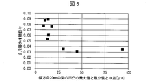
- the difference between the maximum value and the minimum value of the unevenness in the width direction of 20 mm determined by the unevenness measurement, and 50% calculated by the nail penetration test It is a graph which shows a breakdown voltage.
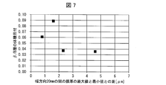
- the difference between the maximum value and the minimum value of the film thickness between 20 mm in the width direction obtained by the film thickness measurement by the cross-sectional SEM and the nail penetration test are calculated. It is a graph which shows the made 50% breakdown voltage.
- the wound body (roll) of the present embodiment is a wound body of a band-shaped porous film having a width of 20 mm or more, and the unevenness in the width direction of the outermost surface of the wound body is made full width at intervals of 1 mm.
- it is a wound body in which the difference between the maximum value and the minimum value of the unevenness in the width direction of 20 mm when measured is less than 25 ⁇ m.
- the “rolled body” is intended to be a roll formed by winding a porous film using a commercially available winder or the like.
- the shape of the wound body is not particularly limited, but the diameter of the circle on the bottom surface and / or the top surface may be a cylindrical shape of about 10 mm to about 1000 mm, or a cylindrical shape of about 25 mm to about 750 mm. Alternatively, it may have a cylindrical shape of about 50 mm to about 500 mm.
- a space where no porous film exists may be formed at the center of the wound body, or the space may not be formed.
- the shape of the space where the porous film is not present may be cylindrical. More specifically, the shape of the space may be a cylindrical shape in which the diameter of the circle on the bottom surface and / or the top surface is about 10 mm to about 300 mm, or a cylindrical shape of about 25 mm to about 250 mm. Alternatively, it may have a cylindrical shape of about 50 mm to about 230 mm.
- the wound body may be formed by rolling the porous film once or may be formed by winding the film multiple times. In the case of multiple times, it may be used 2 to 100,000 times, 2 to 7,000 times, or 1,000 to 7,000 times. Of course, the wound body may be formed by rolling the porous film more than 100,000 times.
- the porous film of the present invention usually has at least one layer (for example, at least A layer), and preferably has two or more layers (for example, at least A layer and B layer). . Specific configurations of the A layer and the B layer will be described later.
- the porous film is a belt-like film and has a width of 20 mm or more.
- the length of the width should just be 20 mm or more, for example, 30 mm or more, 40 mm or more, 50 mm or more, 60 mm or more, 70 mm or more, 80 mm or more, 90 mm or more, 100 mm or more may be sufficient.
- the upper limit of the width is not particularly limited, but may be 1000 mm or 100 mm. Of course, the present invention is not limited to these.
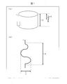
- the difference between the maximum value and the minimum value of the unevenness in the width direction of 20 mm is less than 25 ⁇ m. It is. This point will be described with reference to FIGS. 1 (a) and 1 (b).
- the wound body 1 shown in FIG. 1 (a) has a full width indicated by an arrow 5.
- an arrow 6 indicates an area of 20 mm in the width direction.
- the total width is 20 mm, there is one “region in the width direction 20 mm”, but when the total width is longer than 20 mm, there are a plurality of “regions in the width direction 20 mm”. become.
- Fig. 1 (b) shows an enlarged image of the outermost surface of the wound body surrounded by a rectangle in Fig. 1 (a).
- Fig. 1 (b) shows many unevenness
- the arrow 7 corresponds to the difference between the maximum value and the minimum value of the unevenness in the region in the width direction of 20 mm (in other words, the arrow 6).
- the difference between the maximum value and the minimum value of the unevenness in the width direction of 20 mm is less than 25 ⁇ m, preferably less than 24 ⁇ m, preferably less than 23 ⁇ m, preferably less than 22 ⁇ m, preferably Is less than 21 ⁇ m, preferably less than 20 ⁇ m, preferably less than 19 ⁇ m, preferably less than 18 ⁇ m, preferably less than 17 ⁇ m, preferably less than 16 ⁇ m, preferably less than 15 ⁇ m, preferably less than 14 ⁇ m, preferably less than 13 ⁇ m, preferably less than 12 ⁇ m, preferably Is less than 11 ⁇ m, preferably less than 10 ⁇ m, preferably less than 9 ⁇ m,
- the difference between the maximum value and the minimum value of unevenness in the width direction of 5 mm is less than 20 ⁇ m, preferably less than 19 ⁇ m, preferably less than 18 ⁇ m, preferably less than 17 ⁇ m.
- the lower limit value of the difference between the maximum value and the minimum value of the unevenness in the width direction of 5 mm is not particularly limited, but is preferably 0.5 ⁇ m or more (for example, 0.5 ⁇ m).
- corrugation is not specifically limited, It can measure by the method shown in the Example mentioned later.
- the difference between the maximum value and the minimum value of the irregularities in at least one of a plurality of “regions in the width direction of 20 mm” or at least one of the plurality of “regions in the width direction of 5 mm” is within the above range.
- the “region of 20 mm in the width direction” or “region of 5 mm in the width direction” is preferably a region including the center point of the width of the wound body, and the “region of 20 mm in the width direction” or “width direction” It is more preferable that the central point of the “5 mm region” coincides with the central point of the width of the wound body.
- the wound body of the present embodiment has a maximum value and a minimum value of the film thickness in the width direction of 20 mm. Is less than 1.6 ⁇ m, preferably less than 1.5 ⁇ m, preferably less than 1.4 ⁇ m, preferably less than 1.3 ⁇ m, preferably less than 1.2 ⁇ m, preferably less than 1.1 ⁇ m, preferably 1.
- the lower limit of the difference between the maximum value and the minimum value of the film thickness in the width direction of 20 mm is not particularly limited, but is preferably 0.05 ⁇ m or more (for example, 0.05 ⁇ m), preferably 0.1 ⁇ m. More preferably (for example, 0.1 ⁇ m).
- the difference between the maximum value and the minimum value of the film thickness is not particularly limited, it can be calculated by measuring the film thickness by the method shown in the examples described later and subtracting the minimum value from the maximum value of the measured value. it can.
- the lower limit value of the difference between the maximum value and the minimum value of the unevenness in the width direction of 20 mm, and the lower limit value of the difference between the maximum value and the minimum value of the unevenness in the width direction of 5 mm are 0. 5 ⁇ m or more (for example, 0.5 ⁇ m) is preferable, and the lower limit of the difference between the maximum value and the minimum value of the film thickness in the width direction of 20 mm is preferably 0.05 ⁇ m or more. More preferably, it is 1 ⁇ m or more. If the unevenness is too small, a high tension is required for unwinding when winding the battery, and the separator may be extended by the tension, which may reduce the safety of the battery. Furthermore, if there are too few irregularities, there is a concern that the separator will be charged at the time of unwinding and affect the transport of the separator.
- the porous film may be stretched locally and stretched when an internal short circuit occurs due to metal piercing etc. As a result, the strength of the porous film is lowered, and as a result, the safety of the battery may be lowered.
- the A layer may be one that imparts a shutdown function to the porous film by melting when the battery generates heat and making the porous film (in other words, the separator) nonporous.
- the porous film may have one A layer or a plurality of A layers.
- a layer is not particularly limited, for example, a layer containing polyolefin is preferable.
- polystyrene resin examples include high molecular weight homopolymers or copolymers obtained by polymerizing ethylene, propylene, 1-butene, 4-methyl-1-pentene, 1-hexene and the like.
- the A layer may be a layer containing these polyolefins alone and / or a layer containing two or more of these polyolefins.
- high molecular weight polyethylene mainly composed of ethylene is preferable.
- the reason is that high molecular weight polyethylene mainly composed of ethylene has a shutdown temperature preferable for a normal lithium secondary battery.
- the ratio of the polyolefin component in the A layer is not particularly limited, but is preferably 50% by volume or more of the A layer, more preferably 60% by volume or more, and more preferably 70% by volume or more. It is more preferably at least volume%, more preferably at least 90 volume%, more preferably at least 95 volume%, and most preferably at 100 volume%.
- the layer A may contain components other than polyolefin as long as the function of the layer is not impaired.
- the layer of the porous film has a weight average molecular weight of 1 ⁇ 10 5 to 15 ⁇ 10 6 , more preferably 3 ⁇ 10 5 to 10 ⁇ 10 6 , and most preferably 5 ⁇ 10 5 to 5 ⁇ . It is preferable that 10 6 polymer components are contained. Therefore, the weight average molecular weight of the above-described polyolefin is preferably a weight average molecular weight within these ranges.
- the thickness of the A layer can be, for example, 4 to 50 ⁇ m, but is preferably 5 to 30 ⁇ m. If the thickness is less than 4 ⁇ m, the strength of the porous film may be insufficient, and if the thickness exceeds 50 ⁇ m, the thickness of the porous film may be too thick and the battery capacity may be reduced.
- the porosity of the A layer can be, for example, 20 to 80% by volume, but is preferably 30 to 70% by volume. If the porosity is less than 20% by volume, the amount of electrolyte retained by the porous film may be reduced. If the porosity exceeds 80% by volume, the shutdown function of the porous film may be insufficient. is there. That is, when the battery generates heat violently, the large gap cannot be completely closed by the melted A layer, and as a result, there is a possibility that the current cannot be cut off.
- the viewpoint of the pore size of the A layer is that when the porous film is used as a separator for a non-aqueous electrolyte secondary battery, it exhibits excellent ion permeability and prevents particles from being mixed into the positive electrode and / or the negative electrode. Therefore, it is preferably 3 ⁇ m or less, and more preferably 1 ⁇ m or less.
- the A layer has a structure having pores communicating with the inside thereof, and has a structure capable of transmitting gas and / or liquid from one surface to the other surface.
- the permeability of gas and / or liquid can be represented by the air permeability.
- the air permeability of the A layer can be 30 to 1000 sec / 100 cc, but is preferably 50 to 800 sec / 100 cc.
- the heat-resistant basis weight of the A layer can be 2 to 15 g / m 2 , but is preferably 4 to 12 g / m 2 . If the basis weight is less than 2 g / m 2 , the strength of the porous film may be insufficient, and if it exceeds 15 g / m 2 , the porous film may be too thick and the battery capacity may be reduced. There is.
- the method for producing the A layer is, for example, as described in (1) JP-A-7-29563, after adding a plasticizer to a thermoplastic resin to form a film, the plasticizer is then used with an appropriate solvent.
- the method of removing, etc. are mentioned.
- the A layer is usually manufactured while being transported using a transport device equipped with a stretching mechanism.
- a curved roll e.g., an arcuate roll, a banana roll, a curved roll
- a flat expander roll e.g., a flat expander roll
- a helical roll e.g., a helical roll
- the layer A is formed from a polyolefin resin containing a high molecular weight polyethylene having a weight average molecular weight exceeding 1,000,000 and a low molecular weight polyolefin having a weight average molecular weight of 10,000 or less, from the viewpoint of production cost, It is preferable to manufacture A layer by the method including each process.
- the B layer is a layer other than the A layer, and preferably a layer having a function other than the shutdown function.
- the B layer may be a layer that includes a heat resistant material and has heat resistance at a high temperature at which shutdown occurs.
- the B layer may be a porous layer.
- the B layer may be an adhesive layer that adheres the A layer and another configuration (for example, another B layer or an electrode).
- the porous film having the B layer can have shape stability even at a high temperature. Further, if the layer B is a porous layer containing a heat resistant material, the temperature rises beyond the shutdown temperature of the layer A, and the shape stability at a high temperature is given to the porous film even at a temperature at which the layer A starts to shrink. It is possible to grant.
- the B layer is preferably a layer obtained by coating a coating liquid containing a material for forming the B layer on the A layer.
- the heat-resistant material is defined as a material that does not melt or pyrolyze at a temperature at which the A layer melts (for example, about 130 ° C. when the A layer is made of polyethylene).
- the porous film may have one B layer or a plurality of B layers.
- two or more B layers may be formed so as to sandwich the A layer.
- each of the B layers may contain the same heat-resistant material, may contain different heat-resistant materials, or may have the same adhesive layer.
- the proportion of the heat-resistant material contained in one B layer may exceed 50% by volume of the entire B layer, but is preferably 60% by volume or more, more preferably 70% by volume or more, and more preferably 80% by volume. % Or more, more preferably 90% by volume or more, and still more preferably 95% by volume or more.
- the heat resistant material examples include a heat resistant resin and a heat resistant resin composition containing a heat resistant resin and a filler.
- heat resistant resin examples include polyamide, polyimide, polyamideimide, polycarbonate, polyacetal, polysulfone, polyphenylene sulfide, polyetheretherketone, aromatic polyester, polyethersulfone, polyetherimide, and cellulose ether. These heat resistant resins can be used alone or in admixture of two or more.
- polyamide, polyimide, polyamideimide, polyethersulfone, and polyetherimide are preferable, and polyamide, polyimide, and polyamideimide are more preferable in terms of further improving heat resistance.
- nitrogen-containing aromatic polymers such as aromatic polyamide (para-oriented aromatic polyamide, meta-oriented aromatic polyamide), aromatic polyimide, aromatic polyamideimide, and particularly preferred is aromatic polyamide.
- aromatic polyamide para-oriented aromatic polyamide (hereinafter also referred to as “para-aramid”).
- Para-aramid is obtained by condensation polymerization of a para-oriented aromatic diamine and a para-oriented aromatic dicarboxylic acid halide, and the amide bond is in the para position of the aromatic ring or an oriented position equivalent thereto (for example, 4,4′- It consists essentially of repeating units bonded at opposite orientations, such as biphenylene, 1,5-naphthalene, 2,6-naphthalene, etc., oriented in the opposite direction coaxially or in parallel.
- para-aramid examples include poly (paraphenylene terephthalamide), poly (parabenzamide), poly (4,4′-benzanilide terephthalamide), poly (paraphenylene-4,4′-biphenylenedicarboxylic amide), poly (Paraphenylene-2,6-naphthalenedicarboxylic acid amide), poly (2-chloro-paraphenylene terephthalamide), paraphenylene terephthalamide / 2,6-dichloroparaphenylene terephthalamide copolymer, etc.
- Para-aramid having a structure conforming to the orientation type may be mentioned.
- the aromatic polyimide is preferably a wholly aromatic polyimide produced by condensation polymerization of an aromatic dianhydride and a diamine.
- the dianhydride include pyromellitic dianhydride, 3,3 ′, 4,4′-diphenylsulfonetetracarboxylic dianhydride, 3,3 ′, 4,4′-benzophenonetetracarboxylic dianhydride, and the like.
- Examples include anhydrides, 2,2′-bis (3,4-dicarboxyphenyl) hexafluoropropane, and 3,3 ′, 4,4′-biphenyltetracarboxylic dianhydride.
- diamine examples include oxydianiline, paraphenylenediamine, benzophenonediamine, 3,3′-methylenedianiline, 3,3′-diaminobenzophenone, 3,3′-diaminodiphenylsulfone, 1,5′- Naphthalenediamine is mentioned.
- Aromatic polyamideimides include those obtained from these condensation polymerizations using aromatic dicarboxylic acids and aromatic diisocyanates, and those obtained from these condensation polymerizations using aromatic diacid anhydrides and aromatic diisocyanates.
- Examples of the aromatic dicarboxylic acid include isophthalic acid and terephthalic acid.
- Examples of the aromatic dianhydride include trimellitic anhydride.
- Examples of the aromatic diisocyanate include 4,4'-diphenylmethane diisocyanate, 2,4-tolylene diisocyanate, 2,6-tolylene diisocyanate, orthotolylane diisocyanate, and m-xylene diisocyanate.
- cellulose ethers examples include carboxymethyl cellulose (CMC), hydroxyethyl cellulose (HEC), carboxyethyl cellulose, methyl cellulose, ethyl cellulose, cyanethyl cellulose, and oxyethyl cellulose.
- CMC carboxymethyl cellulose
- HEC hydroxyethyl cellulose
- carboxyethyl cellulose methyl cellulose
- ethyl cellulose cyanethyl cellulose
- oxyethyl cellulose examples include carboxymethyl cellulose (CMC), hydroxyethyl cellulose (HEC), carboxyethyl cellulose, methyl cellulose, ethyl cellulose, cyanethyl cellulose, and oxyethyl cellulose.
- CMC and HEC excellent in chemical and thermal stability are preferable, and CMC is more preferable.
- an organic filler or an inorganic filler for example, ceramic
- an organic filler or an inorganic filler for example, ceramic
- organic filler examples include styrene, vinyl ketone, acrylonitrile, methyl methacrylate, ethyl methacrylate, glycidyl methacrylate, glycidyl acrylate, and methyl acrylate, or a copolymer of two or more kinds, polytetrafluoroethylene, 4 fluorine.
- Fluorinated resins such as fluorinated ethylene-6propylene copolymer, tetrafluoroethylene-ethylene copolymer, polyvinylidene fluoride (polyvinylidene fluoride resin), melamine resin, urea resin, polyethylene, polypropylene, polymethacrylate And the like.
- Inorganic fillers include calcium carbonate, talc, clay, kaolin, silica, hydrotalcite, diatomaceous earth, magnesium carbonate, barium carbonate, calcium sulfate, magnesium sulfate, barium sulfate, aluminum hydroxide, magnesium hydroxide, calcium oxide, oxidation Examples thereof include fine particles made of magnesium, titanium oxide, alumina, mica, zeolite, glass and the like.
- filler such as the hydrate of the filler may be used.
- These fillers can be used alone or in admixture of two or more.
- inorganic oxide fillers are preferable and ⁇ -alumina is more preferable among them in terms of further improving chemical stability and shape stability at high temperatures.
- a filler is a thing which can form the hole of a grade sufficient to ensure the ion permeability of B layer.
- the weight ratio of the filler may be 20 to 99% by weight, preferably 30 to 99% by weight, more preferably 40 to 99% by weight, based on 100% by weight of the heat resistant resin and the filler.
- the amount is preferably 50 to 99% by weight, more preferably 60 to 99% by weight.
- the adhesive material examples include an adhesive resin and an adhesive resin composition containing a filler. If the B layer is an adhesive layer made of an adhesive material, the B layer may be an adhesive layer that adheres the A layer and another configuration (for example, another B layer or an electrode).
- the adhesive resin include fluorine resins such as polyvinylidene fluoride resins.
- polyvinylidene fluoride resin examples include a homopolymer of vinylidene fluoride (that is, polyvinylidene fluoride), a copolymer of vinylidene fluoride and another monomer copolymerizable with the vinylidene fluoride, or a mixture thereof. Can be used. Further, the polyvinylidene fluoride resin may be used together with other polymers (for example, acrylic polymers).
- Examples of monomers copolymerizable with vinylidene fluoride include, for example, tetrafluoroethylene, hexafluoropropylene, trifluoroethylene, trichloroethylene, vinyl fluoride, (meth) acrylic acid, (meth) acrylic acid esters (for example, (meth) And methyl acrylate, ethyl (meth) acrylate), vinyl acetate, vinyl chloride, and acrylonitrile. These can be used alone or in combination of two or more.
- Such a polyvinylidene fluoride resin can be obtained by emulsion polymerization or suspension polymerization. The terminal structure of the polyvinylidene fluoride resin and the catalyst used for the polymerization reaction can be arbitrarily selected.
- the polyvinylidene fluoride resin may be a polyvinylidene fluoride resin A, a polyvinylidene fluoride resin B, or a mixture of a polyvinylidene fluoride resin A and a polyvinylidene fluoride resin B.
- the polyvinylidene fluoride resin A includes a constituent unit derived from vinylidene fluoride and a constituent unit derived from hexafluoropropylene, and the proportion of the constituent unit derived from hexafluoropropylene in all the constituent units is 0.5 mol. % To 1.5 mol% (more preferably 1.0 mol% to 1.4 mol%) of polyvinylidene fluoride resin.
- the polyvinylidene fluoride resin B includes a structural unit derived from vinylidene fluoride and a structural unit derived from hexafluoropropylene, and the proportion of the structural unit derived from hexafluoropropylene in all the structural units is 1.5 mol%. Larger (more preferably, 1.8 mol% or more), it may be a polyvinylidene fluoride resin. In the polyvinylidene fluoride resin B, the proportion of the structural units derived from hexafluoropropylene in all the structural units is preferably less than 25 mol%. If it is the said structure, the adhesiveness of B layer can also be improved.
- acrylic polymer examples include polyacrylic acid, polyacrylate, cross-linked polyacrylic acid, cross-linked polyacrylic ester, polymethacrylic acid ester, cross-linked polymethacrylic acid, and cross-linked polymethacrylic acid ester.
- polyvinylidene fluoride-based resins include polyvinylidene fluoride, a copolymer of vinylidene fluoride and tetrafluoroethylene, a copolymer of vinylidene fluoride and hexafluoropropylene, and a copolymer of vinylidene fluoride and trifluoroethylene. It is preferably used in a blend, a mixture of polyvinylidene fluoride and an acrylic polymer, or a mixture of a polyvinylidene fluoride copolymer and an acrylic polymer.
- the polyvinylidene fluoride resin has, as its structural unit, vinylidene fluoride in an amount of 50 mol% or more, more preferably 60 mol% or more, more preferably 70 mol% or more, more preferably 80 mol% or more, more preferably 90 mol% or more, more preferably It is contained in an amount of 95 mol% or more, more preferably 98 mol% or more.
- the polyvinylidene fluoride resin preferably has a weight average molecular weight (Mw) in the range of 1,000 to 5,000,000, more preferably in the range of 10,000 to 5,000,000, and more preferably in the range of 300,000 to 3,000,000. A range of 300,000 to 2,000,000 is more preferable, and a range of 500,000 to 1,500,000 is more preferable. If it is the said structure, sufficient mechanical physical property in a B layer and shaping
- Mw weight average molecular weight
- the weight average molecular weight of the polyvinylidene fluoride resin can be determined by gel permeation chromatography (GPC) method. For example, the measurement is performed under the following conditions, and the weight average molecular weight of the polyvinylidene fluoride resin can be calculated in terms of polystyrene.
- GPC gel permeation chromatography
- GPC Gel permeation chromatograph Alliance GPC2000 (manufactured by Waters), Column: TSKgel GMH6-HT ⁇ 2 + TSKgel GMH6-HT ⁇ 2 (manufactured by Tosoh Corporation), -Mobile phase solvent: o-dichlorobenzene, Standard sample: monodisperse polystyrene (manufactured by Tosoh Corporation), Column temperature: 140 ° C.
- the oxidation resistance of the positive electrode affects the durability of the battery.
- the polyvinylidene fluoride resin has a high oxygen index and high oxidation resistance
- the durability of the non-aqueous secondary battery can be improved by using the polyvinylidene fluoride resin for the separator.
- the oxidation resistance of the separator can be confirmed by disassembling a battery that has been repeatedly charged and discharged and observing the surface of the separator. In general, when the oxidation resistance of the separator is low, the separator is colored black or brown, and when the oxidation resistance of the separator is high, the separator is not colored.
- the adhesive layer may contain a filler as long as the function of the adhesive layer is not impaired.
- the filler include those described above as the filler in the heat-resistant composition, and among the fillers described above, inorganic oxide fillers are preferable from the viewpoint of further improving the shape stability at high temperatures, and among them ⁇ -alumina. Is more preferable.
- the layer B may contain components such as a dispersant, a plasticizer, and a pH adjuster as long as the function of the layer B is not impaired.
- the thickness of the B layer can be 1 to 25 ⁇ m or less, but is preferably in the range of 5 to 20 ⁇ m or less. If the thickness is less than 1 ⁇ m, the battery may generate heat due to an accident or the like, and the separator may contract without being able to resist the thermal contraction of the layer A. If the thickness exceeds 25 ⁇ m, the thickness of the porous film may be There is a risk that the battery will become thicker and the capacity of the battery will be reduced. When a plurality of B layers are formed (for example, when B layers are formed on both sides of the A layer), the thickness of the B layer is the total thickness of the B layer.
- the configuration and number of layers other than the A layer and B layer of the porous film are not particularly limited, and a desired layer can be used.
- a desired layer can be used.
- an oxidation resistant layer, a layer that shuts down at a lower temperature than the A layer, or a low friction layer can be used. Note that these desired layer functions may be provided in the A layer and / or the B layer.
- Preparation of layer B, porous film and wound body As a method of forming the B layer on the A layer (for example, on one side of the A layer), a method of separately manufacturing the A layer and the B layer and laminating each of the A layer and the A layer (for example, the A layer) A coating liquid containing a material for forming the B layer is formed on one side of the substrate, and the B layer is formed as the coating layer. The method is preferred.
- method 1 As a method for forming the B layer by applying a coating solution containing a heat resistant material as a material for forming the B layer on the A layer, when using a heat resistant resin as the heat resistant material, a method including the following steps (hereinafter may be referred to as “method 1”) can be used.
- a slurry in which a filler is dispersed in a polar organic solvent solution in which a heat resistant resin is dissolved in a polar organic solvent or in a polar organic solvent solution in which a heat resistant resin is dissolved is prepared.
- B A polar organic solvent solution or slurry is applied onto the A layer to form a coating film (coating layer).
- C The heat resistant resin is deposited from the coating film by means of humidification, solvent removal, or immersion in a solvent that does not dissolve the heat resistant resin, and dried.
- a polar organic solvent solution when the heat resistant resin is an aromatic polyamide, a polar amide solvent or a polar urea solvent can be used as the polar organic solvent, for example, N, N-dimethylformamide, N , N-dimethylacetamide, N-methyl-2-pyrrolidone (NMP), and tetramethylurea can be used.
- NMP N-methyl-2-pyrrolidone
- para-aramid When para-aramid is used as the heat-resistant resin, it is preferable to add an alkali metal or alkaline earth metal chloride during the para-aramid polymerization for the purpose of improving the solubility of para-aramid in a solvent.
- the amount of the chloride added to the polymerization system is preferably in the range of 0.5 to 6.0 mol, more preferably in the range of 1.0 to 4.0 mol, per 1.0 mol of the amide group formed by the condensation polymerization. . If the chloride is less than 0.5 mol, the solubility of the resulting para-aramid may be insufficient, and if it exceeds 6.0 mol, the solubility of the chloride in the solvent may be substantially exceeded, which may be undesirable. . In general, if the alkali metal or alkaline earth metal chloride is less than 2% by weight, the solubility of para-aramid may be insufficient. If it exceeds 10% by weight, the alkali metal or alkaline earth metal chloride may be insufficient. May not dissolve in polar organic solvents such as polar amide solvents or polar urea solvents.
- the heat-resistant resin is an aromatic polyimide
- examples of the polar organic solvent for dissolving the aromatic polyimide include dimethyl sulfoxide, cresol, o-chlorophenol, etc. in addition to those exemplified as the solvent for dissolving aramid. It can be used suitably.
- the removal of the medium from the polar organic solvent solution or slurry applied on the A layer is generally performed by drying. It is also possible to prepare a solvent that dissolves in the medium and does not dissolve the used resin, soak in the solvent to replace the medium with the solvent, precipitate the resin, and then dry the medium to remove the medium. it can. In addition, when a polar organic solvent solution or a slurry liquid is apply
- the polar organic solvent solution or the slurry liquid is, for example, at least one selected from the group consisting of a surfactant, a pH adjuster, a dispersant, and a plasticizer, as long as the object of the present invention is not impaired. Can be added.
- a heat resistant resin and a filler are used as the heat resistant material.
- a method including the following steps hereinafter may be referred to as “method 2”. Also good.
- D) A slurry containing a heat-resistant resin, a filler, and a medium is prepared.
- E) The slurry is coated on the A layer to form a coating film (coating layer).
- the medium may be any medium that can uniformly and stably dissolve or disperse the components of the heat-resistant material.
- water alcohols (eg, methanol, ethanol, isopropanol, etc.), acetone, toluene, xylene, hexane, N-methylpyrrolidone, N, N-dimethylacetamide, N, N-dimethylformamide, etc. alone Or what mixed two or more in the range which is compatible is mentioned.
- it is preferable that 80% by weight or more of the medium is water, and only water is more preferable.
- a hydrophilic treatment When water is included as a medium, it is preferable to perform a hydrophilic treatment on the A layer in advance before applying the slurry onto the A layer. By subjecting the A layer to a hydrophilic treatment, the coatability is further improved and a more uniform B layer can be obtained. This hydrophilization treatment is particularly effective when the concentration of water in the medium is high.
- the hydrophilic treatment of the A layer may be performed by any method, and specific methods include chemical treatment using an acid or alkali, corona treatment, plasma treatment, and the like.
- the modification of polyolefin by corona discharge is limited only to the vicinity of the surface of the A layer, without changing the properties inside the A layer, There is an advantage that high coatability can be secured.
- the removal of the medium from the slurry applied on the A layer is generally a drying method.
- the solvent can be removed by drying.
- the temperature which does not change the air permeability of A layer is preferable for the drying temperature of a medium or a solvent.
- At least one selected from the group consisting of a surfactant, a pH adjuster, a dispersant, and a plasticizer can be added to the slurry liquid as long as the object of the present invention is not impaired.
- a method of forming a B layer by applying a coating liquid containing an adhesive material for example, a fluorine resin such as polyvinylidene fluoride resin
- an adhesive material for example, a fluorine resin such as polyvinylidene fluoride resin
- method 3 the following method (hereinafter may be referred to as “method 3”) may be mentioned.
- the B layer as the adhesive layer can be formed on the A layer. it can.
- an adhesive resin is dissolved in a solvent to prepare a coating solution.
- This coating solution is applied onto the A layer and immersed in a suitable coagulating solution. This solidifies the adhesive resin while inducing a phase separation phenomenon.
- the layer made of the adhesive resin can have a porous structure.
- the coagulating liquid is removed by washing with water, and the layer B as an adhesive layer can be formed on the layer A by drying.
- a good solvent that dissolves the adhesive resin can be used.
- a good solvent for example, a polar amide solvent such as N-methylpyrrolidone, dimethylacetamide, dimethylformamide, dimethylformamide and the like can be suitably used.
- a phase separation agent that induces phase separation in addition to the good solvent.
- phase separation agent include water, methanol, ethanol, propyl alcohol, butyl alcohol, butanediol, ethylene glycol, propylene glycol, and tripropylene glycol.
- Such a phase separation agent is preferably added in a range that can ensure a viscosity suitable for coating.
- what is necessary is just to mix or dissolve in the said coating liquid, when mixing a filler and another additive in B layer which is an adhesion layer.
- the composition of the coating solution preferably contains an adhesive resin at a concentration of 3 to 10% by weight.
- the solvent it is preferable to use a mixed solvent containing 60% by weight or more of a good solvent and 40% by weight or less of a phase separation agent from the viewpoint of forming an appropriate porous structure.
- the coagulation liquid water, a mixed solvent of water and the good solvent, or a mixed solvent of water, the good solvent, and the phase separation agent can be used.
- a mixed solvent of water, a good solvent, and a phase separation agent is preferable.
- the mixing ratio of the good solvent and the phase separation agent should be adjusted to the mixing ratio of the mixed solvent used for dissolving the adhesive resin. This is preferable from the viewpoint of productivity.
- the concentration of water is preferably 40 to 90% by weight from the viewpoint of forming a good porous structure and improving productivity.
- the solidification temperature is preferably about ⁇ 20 to 60 ° C. from the viewpoint of controlling the crystallinity.
- the porous film of the present invention can be produced by a dry coating method in addition to the wet coating method described above.
- the dry coating method is a method of obtaining a porous film by coating a coating liquid containing an adhesive resin and a solvent on the layer A and drying the solvent to volatilize and remove the solvent.
- the coating film tends to be a dense film compared to the wet coating method, and it is almost impossible to obtain a porous layer unless a filler or the like is added to the coating liquid.
- a filler or the like is added to the coating liquid.
- the method for obtaining the coating liquid is not particularly limited as long as it is a method capable of obtaining a homogeneous coating liquid.
- the coating liquid is a slurry
- methods such as a mechanical stirring method, an ultrasonic dispersion method, a high pressure dispersion method, and a media dispersion method are preferable, and the high pressure dispersion method is preferable in that it can be more uniformly dispersed. More preferred.
- the mixing order at that time is not particularly limited as long as there is no particular problem such as generation of a precipitate.
- a coating solution containing a heat-resistant material for example, a polar organic solvent solution or slurry
- the method of applying to the A layer is not particularly limited as long as it can be uniformly wet coated, and a conventionally known method can be adopted.
- a capillary coating method, a spin coating method, a slit die coating method, a spray coating method, a roll coating method, a screen printing method, a flexographic printing method, a bar coater method, a gravure coater method, a die coater method, and the like can be employed.
- the thickness of the layer B to be formed is controlled by adjusting the coating amount of the polar organic solvent solution or slurry, the concentration of the heat resistant resin in the polar organic solvent solution or slurry, and the ratio of the filler to the heat resistant resin in the slurry. be able to.
- a coating method of a coating liquid containing a resin such as a heat-resistant resin or an adhesive resin and having a high viscosity
- a bar coater method or a die coater method can be preferably used.
- a coating method of a coating solution having a low viscosity such as a heat-resistant composition containing a large amount of filler
- a gravure coater method can be preferably used.
- when applying a coating liquid to A layer you may apply, supporting A layer with a support body. Examples of the support include a resin film, a metal belt, a drum, and a roll.
- a coating liquid containing a material for forming the B layer is applied to the A layer.
- a construction apparatus is not specifically limited, It is preferable that it is a coating apparatus provided with the wrinkle-stretching mechanism. More specifically, the wrinkle stretching mechanism is preferably a curved roll (for example, an arcuate roll, a banana roll, a curved roll), a flat expander roll, a helical roll, or a pinch expander.
- the wrinkle stretching mechanism is preferably a curved roll (for example, an arcuate roll, a banana roll, a curved roll), a flat expander roll, a helical roll, or a pinch expander.
- a coating apparatus described in JP 2001-316006 A or JP 2002-60102 A can be used as the coating apparatus.
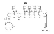
- FIG. 2 and FIG. 3 illustrate an outline of the configuration of an example of a specific coating apparatus, but the present invention is not limited to this.
- 2 is a side view of the coating apparatus
- FIG. 3 is a plan view of the coating apparatus.
- the coating apparatus of the present embodiment includes an unwinding machine 15, and the base material 10 (A layer) unwound from the unwinding machine 15 is sent to the gravure roll 18 via the guide roll 16. . And the coating liquid 11 for forming B layer is applied on the base material 10 by the gravure roll 18. And the base material 10 with which the coating liquid 11 was coated is sent to the following process through the guide roll 17.
- FIG. 1 A layer unwound from the unwinding machine 15 is sent to the gravure roll 18 via the guide roll 16.
- the coating liquid 11 for forming B layer is applied on the base material 10 by the gravure roll 18.
- the base material 10 with which the coating liquid 11 was coated is sent to the following process through the guide roll 17.
- a drying device for drying the coating liquid 11 between the gravure roll 18 and the guide roll 17, and for drying the coating liquid 11 downstream of the guide roll 17. It is also possible to provide a drying device. It is also possible to provide a drying device provided with a pressing roller, or it is possible to provide a drying device not provided with a pressing roller. In addition, the specific example of a drying apparatus is mentioned later.
- the pressing rollers 20 that are paired so as to sandwich the base material 10 in the width direction are such that the axis of the base 2 intersects on the side of the base material 2 in the transport direction. It can be arranged inclining with respect to. The inclination angle can be adjusted to a desired angle. According to the said structure, it can prevent better that a vertical fistula is formed in the base material 10.
- the pressing rollers 20 that are paired so as to sandwich the base material 10 in the width direction are formed between the base material 10 and the pressing roller 20 in the width direction of the base material 10 when both edges of the base material 10 are sandwiched.
- the total of the contact lengths Da and Db can be configured to be 25% or less, preferably 15% or less, more preferably 10% or less of the width dimension D of the substrate 10. According to the said structure, the damage of the base material 10 by the pressing roller 20 can be decreased.
- the outer peripheral surface of the pressing roller 20 has a planar shape or a curved surface shape so that local stress concentration is not applied to the base material 10.
- the pressing roller 20 that is paired so as to sandwich the base material 10 in the thickness direction may have the same outer peripheral surface, or one outer peripheral surface may be planar and the other outer peripheral surface may be It may be curved.
- a rubber ring may be attached to the outer peripheral surface of the pressing roller 20. If it is the said structure, since the dynamic friction coefficient of the pressing roller 20 and the base material 10 will become large, the width
- the coating liquid is applied to the A layer, and then the polymer is precipitated or solidified by dipping in a solvent, and then the polymer is dried. It is preferable to form a work layer.
- Method 2 it is preferable to form the coating layer by applying the coating solution to the A layer and then drying it.
- a normal drying apparatus can be used, but it is preferable to use a drying apparatus having a kneading and stretching mechanism.
- the drying device include a drum dryer. According to the said structure, it can suppress effectively that wrinkles generate
- the B layer resin is deposited or solidified as in the method 1 and method 3 as the coating method of the B layer, it is preferable to use a drying apparatus having a stretching mechanism. In these methods, since the resin is solidified before drying, it is possible to stretch the wrinkles while heating using a drum dryer.
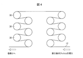
- FIG. 4 illustrates an outline of the configuration of an example of a drying apparatus having a specific kneading mechanism, but the present invention is not limited to this.
- FIG. 4 is a side view of the drying apparatus.
- the drying device is usually provided downstream of the guide roll 17.
- the film 12 (in other words, the A layer after the coating liquid is applied) is conveyed while being in contact with the heating drum 30.
- the number of heating drums 30 may be a desired number.
- the moving path of the film 12 can also be a desired path.
- the film 12 can be dried by contact with the heating drum 30.
- the conveyance speed of the film 12 is not particularly limited, but is preferably 5 m / min to 180 m / min, more preferably 10 m / min to 150 m / min, and preferably 20 m / min to 100 m / min. Further preferred. When the conveying speed is too slow, the productivity of the porous film is lowered. On the other hand, if the conveying speed is too high, poor drying of the porous film occurs.
- the temperature of the heating drum 30 is not particularly limited, but is preferably 40 ° C to 120 ° C. If the temperature is too low, the number of heating rolls 30 needs to be increased, or the porous film may be poorly dried. On the other hand, if the temperature is too high, the porous film contracts and the air permeability increases.
- the diameter of the heating drum 30 is not particularly limited, but is preferably 100 mm to 2000 mm. If the diameter is too large, it is difficult to make the temperature of the heating drum 30 uniform, resulting in poor drying of the porous film. On the other hand, if the diameter is too small, the contact area between the heating drum 30 and the film 12 becomes small, resulting in poor drying of the porous film.
- the magnitude of the tension applied to the film 12 in the width direction is not particularly limited, but is preferably 0.02 to 100 MPa, more preferably 0.5 to 90 MPa per unit sectional area of the film. More preferably, it is 1 to 80 MPa. If the tension is too small, wrinkles may be generated in the porous film, while if the tension is too large, the porous film may be stretched or broken.
- the material of the heating drum 30 is not particularly limited, but is preferably a material that does not cause a chemical change and that has good thermal conductivity.
- austenitic stainless steel specifically, SUS316L
- SUS316L can be used.
- the wound porous body can be obtained by winding the produced porous film, preferably slitting it to a predetermined width, and then winding it.
- the winding body of the present invention can be obtained by appropriately selecting and combining a coating apparatus equipped with a curl-stretching mechanism and a drying apparatus equipped with a curl-stretching mechanism according to the configuration of the B layer. Can do.
- Thickness (unit: ⁇ m): The thickness (total thickness) of the porous film was measured using a high-precision digital length measuring machine manufactured by Mitutoyo Corporation. Specifically, the porous film was cut into a square having a length of 8 cm and the thickness was measured at five points of the porous film, and the average value thereof was taken as the thickness of the porous film.
- the thickness of the A layer was determined by measuring in the same manner as described above.
- the thickness of the B layer was obtained by subtracting the thickness of the A layer from the thickness of the porous film.
- Air permeability (unit: sec / 100cc): The air permeability was measured using an Oken type digital air permeability tester manufactured by Asahi Seiko Co., Ltd. according to JIS P8117.
- Nail penetration test (50% breakdown voltage, unit: V): For 10 cylindrical lithium ion secondary batteries each having a porous film wound body as a separator, each battery was charged to a predetermined test voltage, and then a 2.77 mm ⁇ nail of 1 mm / sec was applied to the center of the battery. A nail penetration test was carried out by penetrating at a speed, and the quality of safety at the voltage was judged.
- the 50% breakdown voltage was calculated according to the method described in “JIS K 7211 Hard plastic drop impact test method general rules”.
- the calculated 50% breakdown voltage means the battery voltage of the non-aqueous electrolyte secondary battery in which abnormal heat generation is suppressed when an internal short circuit occurs due to nail penetration. Abnormal heat generation is suppressed when the battery voltage of the water electrolyte secondary battery is equal to or lower than the 50% breakdown voltage.
- the 50% breakdown voltage is represented by the following formula (1).
- V 50 VI + d [ ⁇ (i ⁇ ni) / N ⁇ 1/2] (1)
- V 50 50% breakdown voltage
- VI Test voltage when the voltage level (i) is 0 (voltage in which “ ⁇ ” and “x” coexist in the test voltage and the number of “x” is large)
- d Voltage interval (V) when the test voltage is raised or lowered
- ⁇ 1/2 When ni and N are used, the number (total number) of “ ⁇ ” batteries is +1/2, and when the number of “ ⁇ ” batteries (total number) is used, ⁇ 1 / 2.
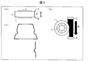
- the wound body 1 was formed by rolling a porous film around the bobbin 2. Then, as shown in FIGS. 5 (a) and 5 (b), using a laser (LS-7070M manufactured by Keyence Corporation), a wound body 1 (in other words, a secondary film) While irradiating light to the side surface of the heat resistant (laminated) separator for a battery), the wound body 1 is moved in the width direction (see the arrow in FIG. 5A, in other words, in front of the sheet of FIG. 5B). The direction of deviation from the reference point between AB was measured with respect to the full width at 1 mm intervals.
- LS-7070M manufactured by Keyence Corporation
- the laser described above includes a laser source 3 that emits laser light and a laser detector 4 that detects the laser light.
- the sheet was prepared by rolling the polyolefin resin composition with a pair of rolls having a surface temperature of 150 ° C.
- the sheet is immersed in an aqueous hydrochloric acid solution (hydrochloric acid 4 mol / L, nonionic surfactant 0.5% by weight) to remove calcium carbonate, and subsequently stretched at an arbitrary magnification at 105 ° C.,
- a polyolefin porous film (A layer) having a thickness of 16 ⁇ m, a porosity of 53%, and an air permeability of 100 seconds / 100 cc was obtained.
- alumina powder (AKP3000 (manufactured by Sumitomo Chemical Co., Ltd.), true specific gravity: 4.0 g / cm 3 ) are added and mixed at a weight ratio of “3: 100”, and high pressure dispersion is performed.
- a slurry for forming a ceramic was prepared.
- NMP N-methyl-2-pyrrolidone
- alumina powder (alumina C (manufactured by Nippon Aerosil Co., Ltd.), true specific gravity: 3.2 g / cm 3 ) 6 g
- alumina powder (advanced alumina AA-03 (manufactured by Sumitomo Chemical Co., Ltd.), true specific gravity: 4.0 g / Cm 3 ) 6 g was mixed to obtain 12 g of an alumina powder mixture.
- a para-aramid solution having a para-aramid concentration of 1.75% by weight and 12 g of an alumina powder mixture were mixed and stirred for 240 minutes to obtain an alumina powder-containing para-aramid solution. Further, the alumina powder-containing para-aramid solution was filtered through a 1000 mesh wire mesh. Thereafter, 0.73 g of calcium oxide was added to the filtrate, and the mixture was neutralized by stirring for 240 minutes, and degassed under reduced pressure to obtain an aramid forming slurry.
- a porous film having a predetermined thickness in which a ceramic layer was laminated on one side or both sides of the A layer was obtained.
- Table 1 shows the physical properties of the obtained porous film measured by the above method.
- the obtained porous film was slit to a width of 60.9 mm and wound on a bobbin having an inner diameter of 3 inches and an outer diameter of 6 inches to obtain a wound body.
- NMP was applied to the lower surface of the extracted A layer with a microgravure coater, and an aramid-forming slurry was applied to the upper surface with a bar coater to a predetermined thickness.
- the A layer after coating was passed through a constant temperature and humidity chamber (temperature 50 ° C., relative humidity 70%) to precipitate para-aramid from the coated film.
- a guide roll is set in the water washing apparatus (ion exchange water is injected at 10 liters / minute, and the ion exchange water filled in the film is discharged at the same speed as the injection speed. NMP and calcium chloride were removed from the A layer.
- a porous film having a predetermined thickness obtained by laminating an aramid layer on one side of the A layer was obtained.
- Table 1 shows the physical properties of the obtained porous film measured by the above method.
- the obtained porous film was slit to a width of 60.9 mm and wound on a bobbin having an inner diameter of 3 inches and an outer diameter of 6 inches to obtain a wound body.
- Table 1 shows the physical properties of the obtained porous film measured by the above method.
- the obtained porous film was slit to a width of 60.9 mm and wound on a bobbin having an inner diameter of 3 inches and an outer diameter of 6 inches to obtain a wound body.
- a positive electrode was prepared using a positive electrode active material, a conductive agent, binder 1, binder 2, and water.
- a positive electrode active material (cell seed C-10N (manufactured by Nippon Chemical Industry Co., Ltd.), LiCoO 2 , true specific gravity 4.8 g / cm 3 ): conductive agent (acetylene black (manufactured by Denki Kagaku Kogyo Co., Ltd.), true specific gravity 2.
- Binder 1 (PTFE31-JR (Mitsui DuPont Fluoro Chemical Co., Ltd.), true specific gravity 2.2 g / cm 3 ): Binder 2 (Serogen 4H (Daiichi Kogyo Seiyaku Co., Ltd.)), Weighed each so that the mixing ratio of true specific gravity 1.4 g / cm 3 ) would be 92: 2.7: 4.55: 0.75 (weight ratio).
- the positive electrode active material, the conductive agent and the binder 1 are added and kneaded, and water is added again so that the viscosity becomes 2700 ⁇ 1000 cp.
- the positive electrode mixture was obtained by adjusting.
- the positive electrode mixture was applied to a predetermined portion on both surfaces of an aluminum foil having a thickness of 20 ⁇ m and no voids, which was a positive electrode current collector sheet, and then dried, and then the thickness of the coating film was 140 ⁇ m (apparent density 3.5 g) by a roll press. / Cm 3 ) to obtain a positive electrode having a width of 54 mm.
- a negative electrode was produced using the negative electrode active material 1, the negative electrode active material 2, a binder, and water.
- negative electrode active material 1 (BF15SP (manufactured by Chuetsu Graphite Industries Co., Ltd.), true specific gravity 2.2 g / cm 3 ): negative electrode active material 2 (CG-RA (manufactured by Nippon Graphite Trading Co., Ltd.), true specific gravity 2 .2g / cm 3): binder (Cellogen 4H (Dai-ichi Kogyo Seiyaku Co., Ltd.), true specific gravity: mixing ratio of 1.4 g / cm 3) is 58.8: 39.2: 2 (weight ratio) Each was weighed to have a composition.
- BF15SP manufactured by Chuetsu Graphite Industries Co., Ltd.
- true specific gravity 2 (CG-RA (manufactured by Nippon Graphite Trading Co., Ltd.), true specific gravity 2 .2g / cm 3): binder (Cellogen 4H (Dai-ichi Kogyo Seiyaku Co.,
- the negative electrode mixture was applied to a predetermined portion on both sides of a copper foil having a thickness of 12 ⁇ m and no voids, which was a negative electrode current collector sheet, and then dried, and then the thickness of the coating film was 140 ⁇ m (apparent density 1.45 g) by a roll press. / Cm 3 ) to obtain a negative electrode having a width of 56 mm.
- the obtained electrode group was put into a battery can for 18650 cylindrical batteries, necked with a desktop lathe, welded to the bottom of the negative electrode tab and the lid of the positive electrode tab, and then vacuum dried.
- Test results (film thickness measurement)> The measurement results of the thickness of each layer are shown below.
- Test result (0% breakdown voltage)>
- the cylindrical lithium ion secondary battery obtained in ⁇ 5-3> was subjected to the nail penetration test by the above method, and the results of calculating the 50% breakdown voltage are shown in Table 6, FIG. 6 and FIG.
- the 50% breakdown voltage ⁇ excluding the influence of the A layer is based on the value of the 50% breakdown voltage of the batteries using the porous films prepared in Examples 1 to 6 and Comparative Examples 1 to 3, and It is obtained by subtracting the value of the 50% breakdown voltage of a battery using a single film.
- a B layer containing a heat resistant material was used as the B layer.
- the 50% breakdown voltage is proportional to the volume basis weight of the layer containing the heat resistant material. Therefore, in order to exclude the influence of the volume basis weight, “volume basis weight of ⁇ / B layer” was calculated and compared.
- the “beta / B layer volume per unit area” of the batteries of Examples 1 to 6 was higher than the “ ⁇ / B layer per unit area” of Comparative Examples 1 to 3, and the batteries of Examples 1 to 6 were Even when an internal short circuit occurred, the battery was found to be highly safe.
- the present invention can be widely used in the field of manufacturing batteries (for example, non-aqueous electrolyte secondary batteries) that can ensure high safety. More specifically, the present invention can be widely used in the field of manufacturing separators for batteries (for example, non-aqueous electrolyte secondary batteries).
- batteries for example, non-aqueous electrolyte secondary batteries
Landscapes
- Chemical & Material Sciences (AREA)
- Chemical Kinetics & Catalysis (AREA)
- Electrochemistry (AREA)
- General Chemical & Material Sciences (AREA)
- Engineering & Computer Science (AREA)
- Manufacturing & Machinery (AREA)
- Organic Chemistry (AREA)
- Materials Engineering (AREA)
- Wood Science & Technology (AREA)
- Life Sciences & Earth Sciences (AREA)
- Health & Medical Sciences (AREA)
- Medicinal Chemistry (AREA)
- Polymers & Plastics (AREA)
- Cell Separators (AREA)
- Manufacture Of Porous Articles, And Recovery And Treatment Of Waste Products (AREA)
- Laminated Bodies (AREA)
- Application Of Or Painting With Fluid Materials (AREA)
- Coating Of Shaped Articles Made Of Macromolecular Substances (AREA)
Abstract
Description
(a)多孔質フィルムの捲回体であって、最表面の凹凸が小さな捲回体をセパレータとして用いれば、安全性が高い電池(特に、内部短絡が生じた時の安全性が高い電池)を作製することができること、
(b)多孔質フィルムの原料となる膜に対して、幅方向に向かう張力をかけながら多孔質フィルムを製造すると、凹凸が小さな多孔質フィルムを作製することができ、当該多孔質フィルムを用いて捲回体を形成すれば、最表面の凹凸が小さな捲回体を製造することができること、
(c)多孔質フィルムの原料となる膜の材質と、塗工層の塗工方法と、多孔質フィルムの原料となる膜に張力を加える方法と、の組み合わせには、凹凸が小さな多孔質フィルムを作製するにあたって好ましい組み合わせが存在すること。
本実施の形態の捲回体(ロール)は、20mm以上の幅を有する帯状の多孔質フィルムの捲回体であって、捲回体の最表面の幅方向の凹凸を、1mm間隔で全幅に対して測定したときの、幅方向20mmの間の凹凸の最大値と最小値との差が25μm未満である、捲回体である。
A層は、電池が発熱したときに溶融して、多孔質フィルム(換言すれば、セパレータ)を無孔化することにより、多孔質フィルムにシャットダウン機能を付与するものであり得る。
(A)高分子量ポリエチレン100重量部と、低分子量ポリオレフィン5~200重量部と、炭酸カルシウム等の無機充填剤100~400重量部と、を混練してポリオレフィン樹脂組成物を得る工程、
(B)前記ポリオレフィン樹脂組成物を用いてシートを成形する工程、
(C)工程(B)で得られたシート中から無機充填剤を除去する工程、および、
(D)工程(C)で得られたシートを延伸してA層を得る工程、
を含む方法でA層を製造することができる。
B層は、A層以外の層であり、好ましくは、シャットダウン機能以外の機能を有する層である。
・GPC:ゲル浸透クロマトグラフAlliance GPC2000型(Waters製)、
・カラム:TSKgel GMH6-HT×2 + TSKgel GMH6-HT×2(東ソー(株)製)、
・移動相溶媒:o-ジクロロベンゼン、
・標準試料:単分散ポリスチレン(東ソー(株)製)、
・カラム温度:140℃。
B層をA層の上(例えば、A層の片面上)に形成させる方法としては、A層とB層とを別々に製造してそれぞれを積層する方法、A層の上(例えば、A層の片面上)に、B層を形成するための材料を含有する塗工液を塗工して、塗工層としてB層を形成する方法等が挙げられるが、より簡便であることから後者の方法が好ましい。
(a)耐熱性樹脂が極性有機溶媒に溶解した極性有機溶媒溶液、または耐熱性樹脂が溶解した極性有機溶媒溶液にフィラーが分散したスラリーを調製する。
(b)極性有機溶媒溶液、または、スラリーをA層の上に塗工し、塗工膜(塗工層)を形成する。
(c)加湿、溶媒除去あるいは耐熱性樹脂を溶解しない溶媒への浸漬等の手段によって、塗工膜から耐熱性樹脂を析出させて、乾燥する。
(d)耐熱性樹脂およびフィラー、並びに、媒体を含むスラリーを調製する。
(e)該スラリーをA層の上に塗工し、塗工膜(塗工層)を形成する。
(f)媒体を除去する。
(1)厚み(単位:μm):
多孔質フィルムの厚み(全体厚み)は、株式会社ミツトヨ製の高精度デジタル測長機を用いて測定した。具体的に、多孔質フィルムを一辺の長さ8cmの正方形に切り、当該多孔質フィルムの5点にて厚みの測定を行い、それらの平均値を多孔質フィルムの厚みとした。
多孔質フィルムから、一辺の長さが0.08mの正方形のサンプルを切り出し、切り出したサンプルの重量W(g)を測定した。同様に、ポリオレフィン多孔質フィルム(A層)から、一辺の長さ0.08mの正方形のサンプルを切り出し、切り出したサンプルの重量Wa(g)を測定した。そして、WからWaを差し引いて、B層の重量Wb(g)(=W-Wa)を算出した。
上記(2)を参考にして、耐熱目付(=Wb/S)を算出した。
透気度を、JIS P8117 に準拠して、旭精工株式会社製の王研式デジタル透気度試験機を用いて測定した。
多孔質フィルムの捲回体をセパレータとして備える円筒型のリチウムイオン二次電池10個について、それぞれ所定の試験電圧まで充電した後、電池の中心部に対し、2.77mmφの釘を1mm/secの速度で貫通させて釘刺し試験を実施し、当該電圧における安全性の良否判定を行った。
V50:50%破壊電圧、
VI:電圧水準(i)が0のときの試験電圧(試験電圧において、「○」と「×」とが共存する電圧であり、かつ、「×」の数が多い電圧)、
d:試験電圧を上下させる場合の電圧間隔(V)、
i:VIのときを0とし、一つずつ増減する電圧水準(i=・・・-3,-2,-1,0,1,2,3・・・)(例えば、VIから0.05V上げた場合はi=1、0.05V下げた場合はi=-1となる。)、
ni:各電圧水準での釘刺し試験において「○」となった(または「×」となった)電池の数、
N:当該電池の全ての釘刺し試験において「○」となった(または「×」となった)電池の総数)(N=Σni)、
(「○」となった電池の数(総数)、または「×」となった電池の数(総数)のいずれを使用するかは、当該電池の全釘刺し試験で数の多かった方の結果を使用する。なお同数の場合は、どちらを使用してもよい。)、
±1/2:niおよびNとして、「○」となった電池の数(総数)を使用した場合は+1/2、「×」となった電池の数(総数)を使用した場合は-1/2。
図5(a)に示すように、ボビン2の周りに、多孔質フィルムを捲いて捲回体1を形成した。そして、図5(a)、および、図5(b)に示すように、レーザー(キーエンス株式会社製のLS-7070M)を用いて、多孔質フィルムの捲回体1(換言すれば、2次電池用耐熱(積層)セパレータの捲回体)の側面に光を照射しながら、捲回体1を幅方向(図5(a)の矢印参照、換言すれば、図5(b)の紙面手前から紙面奥へ向かう方向)に移動させ、AB間の基準点からのずれ量を1mm間隔で全幅に対して測定した。AB間に傾きがある場合には、最小二乗法で傾きを補正し(図5(c)参照)、基準点からのずれ量を測定した。なお、図5(b)中、上述したレーザーは、レーザー光を発するレーザー源3および、レーザー光を検知するレーザー検知器4を備えている。
捲回体の最外周の多孔質フィルムをTD(Transverse Direction)方向にミクロトームで切断して回収し、当該多孔質フィルムの幅方向の中心点から±10mmの範囲の間の4点についてSEM観察して、捲回体の最外周の多孔質フィルムの厚みを0.1μm単位まで測定した。測定した4点の厚みにおいて、「最大厚み-最小厚み」を計算し、計算された値を幅方向20mmの間の膜厚の最大値と最小値との差とした。
高分子量ポリエチレン粉末(GUR4032(ティコナ株式会社製))を70重量%、重量平均分子量1000のポリエチレンワックス(FNP-0115(日本精鑞株式会社製))30重量%、この高分子量ポリエチレン粉末とポリエチレンワックスの合計100重量部に対して、酸化防止剤(Irg1010(チバ・スペシャリティ・ケミカルズ株式会社製))0.4重量部、酸化防止剤(P168(チバ・スペシャリティ・ケミカルズ株式会社製))0.1重量部、ステアリン酸ナトリウム1.3重量部を加え、さらに全体積に対して38体積%となるように平均粒径0.1μmの炭酸カルシウム(丸尾カルシウム株式会社製)を加え、これらを粉末のままヘンシェルミキサーで混合した後、二軸混練機で溶融混練してポリオレフィン樹脂組成物とした。
<3-1.セラミック形成用スラリー>
「純水:イソプロピルアルコール」の重量比が「95:5」である媒体に、固形分濃度が28重量%となるようにカルボキシメチルセルロース(CMC)(1110(ダイセルファインケム株式会社製)、真比重:1.6g/cm3)とアルミナ粉末(AKP3000(住友化学株式会社製)、真比重:4.0g/cm3)と、を「3:100」の重量比で添加、混合して、高圧分散により、セラミック形成用スラリーを調製した。
撹拌翼、温度計、窒素流入管および粉体添加口を有する、3リットルのセパラブルフラスコを使用して、パラアラミド(ポリ(パラフェニレンテレフタルアミド))の製造を行った。
<4-1.実施例1、実施例2および実施例4~6の多孔質フィルムの製造>
グラビア塗工機を用いて、コロナ処理を行ったA層の片面(実施例1、実施例4および実施例5)または両面(実施例2および実施例6)に、ピンチロール(ピンチエキスパンダ)を通しながら、セラミック形成用スラリーを直接塗布し、A層およびセラミック形成用スラリーを乾燥させた。なお、乾燥温度は、70℃であった。
A層のロール(幅300mm、長さ300m)を巻き出し機に取り付け、A層を引き出しながら、A層の片面にアラミド形成用スラリーを塗布し、連続的に多孔質フィルムを作製した。
グラビア塗工機を用いて、コロナ処理を行ったA層の両面に、セラミック形成用スラリーをピンチロールを通さずに直接塗布し、A層およびセラミック形成用スラリーを乾燥させた。

<5-1.正極の作製>
正極活物質、導電剤、バインダー1、バインダー2、および水を用いて、正極を作製した。
負極活物質1、負極活物質2、バインダー、および水を用いて、負極を作製した。
実施例1~6、比較例1~3で作製された多孔質フィルム(幅60.9mm、長さ700mm)をセパレータとして用い、さらに、正極タブ(アルミ)を溶接した上記正極(幅54mm、長さ560mm)、負極タブ(ニッケル)を溶接した上記負極(幅56mm、長さ600mm)を用いて、正極、多孔質フィルム、負極の順に積層して巻回した。
各層の厚みの測定結果を以下に示す。


<5-3>で得られた円筒型のリチウムイオン二次電池について、上記の方法で釘刺し試験を行い、50%破壊電圧を算出した結果を表6、図6および図7に示す。なお、A層の影響を除いた50%破壊電圧βとは、実施例1~6、比較例1~3で作製された多孔質フィルムを用いた電池の50%破壊電圧の値から、A層単独フィルムを用いた電池の50%破壊電圧の値を引いたものである。

2 ボビン
3 レーザー源
4 レーザー検知器
5・6・7 矢印
10 基材
11 塗工液
12 フィルム
15 巻き出し機
16・17 ガイドロール
18 グラビアロール
20 押付ローラ
30 加熱ドラム
Claims (11)
- 20mm以上の幅を有する帯状の多孔質フィルムの捲回体であって、
上記捲回体の最表面の幅方向の凹凸を、1mm間隔で全幅に対して測定したときの、幅方向20mmの間の凹凸の最大値と最小値との差が25μm未満であることを特徴とする捲回体。 - 上記捲回体の最外周の多孔質フィルムの、幅方向20mmの間の膜厚の最大値と最小値との差が1.6μm以下であることを特徴とする請求項1に記載の捲回体。
- 上記多孔質フィルムが、ポリオレフィンを含む層を有することを特徴とする請求項1または2に記載の捲回体。
- 上記多孔質フィルムが、ポリオレフィンを含む層と、該ポリオレフィンを含む層の上に塗工されて形成された塗工層と、を有することを特徴とする請求項1~3の何れか1項に記載の捲回体。
- 上記塗工が、皺伸ばし機構を備えた塗工装置を用いて行われることを特徴とする請求項4に記載の捲回体。
- 上記皺伸ばし機構が、ピンチエキスパンダであることを特徴とする請求項5に記載の捲回体。
- 上記塗工層は、塗工の後に乾燥されて形成された層であり、
上記乾燥が、皺伸ばし機構を有する乾燥装置を用いて行われることを特徴とする請求項4~6の何れか1項に記載の捲回体。 - 上記乾燥装置が、ドラム乾燥器であることを特徴とする請求項7に記載の捲回体。
- 上記多孔質フィルムが、耐熱性樹脂を含む層、および、接着性樹脂を含む層からなる群から選択される少なくとも1つの層と、ポリオレフィンを含む層と、を有することを特徴とする請求項1~3の何れか1項に記載の捲回体。
- 上記多孔質フィルムが、ポリオレフィンを含む層と、耐熱性樹脂を含む層と、を有することを特徴とする請求項1~3の何れか1項に記載の捲回体。
- 請求項4に記載の捲回体の製造方法であって、
ポリオレフィンを含む層の上に、塗工層を形成するための塗工液を塗工する工程を含むことを特徴とする製造方法。
Priority Applications (4)
| Application Number | Priority Date | Filing Date | Title |
|---|---|---|---|
| CN201580037479.9A CN106661257A (zh) | 2014-08-29 | 2015-08-28 | 多孔膜的卷绕体及其制造方法 |
| JP2015544244A JPWO2016031990A1 (ja) | 2014-08-29 | 2015-08-28 | 多孔質フィルムの捲回体、および、その製造方法 |
| US15/316,972 US10059085B2 (en) | 2014-08-29 | 2015-08-28 | Wound body of porous film, and manufacturing method thereof |
| KR1020167013979A KR101749878B1 (ko) | 2014-08-29 | 2015-08-28 | 다공질 필름의 권회체 및 그의 제조 방법 |
Applications Claiming Priority (2)
| Application Number | Priority Date | Filing Date | Title |
|---|---|---|---|
| JP2014-175485 | 2014-08-29 | ||
| JP2014175485 | 2014-08-29 |
Publications (1)
| Publication Number | Publication Date |
|---|---|
| WO2016031990A1 true WO2016031990A1 (ja) | 2016-03-03 |
Family
ID=55399871
Family Applications (1)
| Application Number | Title | Priority Date | Filing Date |
|---|---|---|---|
| PCT/JP2015/074536 WO2016031990A1 (ja) | 2014-08-29 | 2015-08-28 | 多孔質フィルムの捲回体、および、その製造方法 |
Country Status (5)
| Country | Link |
|---|---|
| US (1) | US10059085B2 (ja) |
| JP (2) | JPWO2016031990A1 (ja) |
| KR (1) | KR101749878B1 (ja) |
| CN (1) | CN106661257A (ja) |
| WO (1) | WO2016031990A1 (ja) |
Cited By (1)
| Publication number | Priority date | Publication date | Assignee | Title |
|---|---|---|---|---|
| WO2017010480A1 (ja) * | 2015-07-15 | 2017-01-19 | 三菱樹脂株式会社 | 積層多孔フィルム、非水電解液二次電池用セパレータ、非水電解液二次電池、及び積層多孔フィルムの製造方法 |
Families Citing this family (1)
| Publication number | Priority date | Publication date | Assignee | Title |
|---|---|---|---|---|
| JP2023137849A (ja) * | 2022-03-18 | 2023-09-29 | 日東電工株式会社 | 積層体 |
Citations (4)
| Publication number | Priority date | Publication date | Assignee | Title |
|---|---|---|---|---|
| JP2001316006A (ja) * | 2000-05-12 | 2001-11-13 | Sumitomo Chem Co Ltd | 基材搬送装置および基材塗工体の製造方法 |
| JP2002060102A (ja) * | 2000-08-23 | 2002-02-26 | Sumitomo Chem Co Ltd | 基材搬送装置および基材塗工体の製造方法 |
| WO2011024849A1 (ja) * | 2009-08-25 | 2011-03-03 | 旭化成イーマテリアルズ株式会社 | 微多孔膜捲回体及びその製造方法 |
| WO2013080701A1 (ja) * | 2011-12-02 | 2013-06-06 | 三菱樹脂株式会社 | 積層多孔フィルムロール及びその製造方法 |
Family Cites Families (11)
| Publication number | Priority date | Publication date | Assignee | Title |
|---|---|---|---|---|
| JPH0648059A (ja) | 1992-07-30 | 1994-02-22 | Asahi Chem Ind Co Ltd | 感熱孔版印刷用原紙の製造方法 |
| JP3050021B2 (ja) | 1993-05-11 | 2000-06-05 | 三菱化学株式会社 | バッテリーセパレーター及びそれを用いたリチウム電池 |
| JP3597224B2 (ja) | 1994-07-26 | 2004-12-02 | 東燃化学株式会社 | ポリオレフィンフィルムの平滑化方法 |
| JP3526971B2 (ja) | 1995-06-22 | 2004-05-17 | 花王株式会社 | 多孔性シート及びその製造方法 |
| JP5361207B2 (ja) * | 2008-02-20 | 2013-12-04 | 住友化学株式会社 | 多孔性フィルムを有するセパレータ |
| JP2009205959A (ja) | 2008-02-28 | 2009-09-10 | Teijin Ltd | 非水電解質電池セパレータの製造方法 |
| CN103597017A (zh) | 2011-06-13 | 2014-02-19 | 日东电工株式会社 | 热固性树脂多孔片的制造方法和制造装置、以及热固性树脂多孔片和片卷筒 |
| JP5752559B2 (ja) | 2011-10-27 | 2015-07-22 | 株式会社ヒラノテクシード | 塗工装置 |
| JP5694971B2 (ja) | 2012-02-08 | 2015-04-01 | 住友化学株式会社 | ポリオレフィン微多孔フィルムの製造方法及び積層多孔フィルムの製造方法 |
| US9276244B2 (en) | 2012-02-08 | 2016-03-01 | Sumitomo Chemical Company, Limited | Method for producing polyolefin porous film, and laminated porous film |
| JP6269062B2 (ja) | 2012-05-14 | 2018-01-31 | 東レ株式会社 | フィルムロール |
-
2015
- 2015-08-28 CN CN201580037479.9A patent/CN106661257A/zh active Pending
- 2015-08-28 KR KR1020167013979A patent/KR101749878B1/ko active IP Right Grant
- 2015-08-28 US US15/316,972 patent/US10059085B2/en active Active
- 2015-08-28 WO PCT/JP2015/074536 patent/WO2016031990A1/ja active Application Filing
- 2015-08-28 JP JP2015544244A patent/JPWO2016031990A1/ja active Pending
-
2016
- 2016-06-17 JP JP2016121234A patent/JP2017022092A/ja active Pending
Patent Citations (4)
| Publication number | Priority date | Publication date | Assignee | Title |
|---|---|---|---|---|
| JP2001316006A (ja) * | 2000-05-12 | 2001-11-13 | Sumitomo Chem Co Ltd | 基材搬送装置および基材塗工体の製造方法 |
| JP2002060102A (ja) * | 2000-08-23 | 2002-02-26 | Sumitomo Chem Co Ltd | 基材搬送装置および基材塗工体の製造方法 |
| WO2011024849A1 (ja) * | 2009-08-25 | 2011-03-03 | 旭化成イーマテリアルズ株式会社 | 微多孔膜捲回体及びその製造方法 |
| WO2013080701A1 (ja) * | 2011-12-02 | 2013-06-06 | 三菱樹脂株式会社 | 積層多孔フィルムロール及びその製造方法 |
Cited By (2)
| Publication number | Priority date | Publication date | Assignee | Title |
|---|---|---|---|---|
| WO2017010480A1 (ja) * | 2015-07-15 | 2017-01-19 | 三菱樹脂株式会社 | 積層多孔フィルム、非水電解液二次電池用セパレータ、非水電解液二次電池、及び積層多孔フィルムの製造方法 |
| JPWO2017010480A1 (ja) * | 2015-07-15 | 2018-04-26 | 三菱ケミカル株式会社 | 積層多孔フィルム、非水電解液二次電池用セパレータ、非水電解液二次電池、及び積層多孔フィルムの製造方法 |
Also Published As
| Publication number | Publication date |
|---|---|
| JP2017022092A (ja) | 2017-01-26 |
| US20170173927A1 (en) | 2017-06-22 |
| KR20160075741A (ko) | 2016-06-29 |
| JPWO2016031990A1 (ja) | 2017-04-27 |
| CN106661257A (zh) | 2017-05-10 |
| US10059085B2 (en) | 2018-08-28 |
| KR101749878B1 (ko) | 2017-06-21 |
Similar Documents
| Publication | Publication Date | Title |
|---|---|---|
| JP5920496B2 (ja) | 積層多孔質フィルムおよび非水電解液二次電池 | |
| JP5932161B1 (ja) | 積層体、セパレータ及び非水二次電池 | |
| KR101572289B1 (ko) | 다공질 필름, 그것을 포함하는 적층 다공질 필름 및 세퍼레이터 | |
| JP5969683B1 (ja) | 非水電解液二次電池用セパレータ、非水電解液二次電池用積層セパレータ、非水電解液二次電池用部材および非水電解液二次電池 | |
| JP5714441B2 (ja) | セパレータ | |
| JP5476844B2 (ja) | 多孔質フィルム、電池用セパレータ及び電池 | |
| WO2012043501A1 (ja) | スラリー及び該スラリーを使用したセパレータの製造方法 | |
| US11031655B2 (en) | Nonaqueous electrolyte secondary battery separator and method of producing same | |
| WO2016031990A1 (ja) | 多孔質フィルムの捲回体、および、その製造方法 | |
| US20190372074A1 (en) | Nonaqueous electrolyte secondary battery separator | |
| JP5476845B2 (ja) | 多孔質フィルム、電池用セパレータ及び電池 | |
| JP6671255B2 (ja) | 非水電解液二次電池用セパレータ、非水電解液二次電池用積層セパレータ、非水電解液二次電池用部材および非水電解液二次電池 | |
| JP7489767B2 (ja) | 非水電解液二次電池用セパレータの製造方法、非水電解液二次電池用部材の製造方法および非水電解液二次電池の製造方法 |
Legal Events
| Date | Code | Title | Description |
|---|---|---|---|
| ENP | Entry into the national phase |
Ref document number: 2015544244 Country of ref document: JP Kind code of ref document: A |
|
| 121 | Ep: the epo has been informed by wipo that ep was designated in this application |
Ref document number: 15836646 Country of ref document: EP Kind code of ref document: A1 |
|
| ENP | Entry into the national phase |
Ref document number: 20167013979 Country of ref document: KR Kind code of ref document: A |
|
| WWE | Wipo information: entry into national phase |
Ref document number: 15316972 Country of ref document: US |
|
| NENP | Non-entry into the national phase |
Ref country code: DE |
|
| 122 | Ep: pct application non-entry in european phase |
Ref document number: 15836646 Country of ref document: EP Kind code of ref document: A1 |