WO2016027510A1 - 超音波診断画像生成装置、及び方法 - Google Patents
超音波診断画像生成装置、及び方法 Download PDFInfo
- Publication number
- WO2016027510A1 WO2016027510A1 PCT/JP2015/061794 JP2015061794W WO2016027510A1 WO 2016027510 A1 WO2016027510 A1 WO 2016027510A1 JP 2015061794 W JP2015061794 W JP 2015061794W WO 2016027510 A1 WO2016027510 A1 WO 2016027510A1
- Authority
- WO
- WIPO (PCT)
- Prior art keywords
- unit
- ultrasonic diagnostic
- region
- image generation
- diagnostic image
- Prior art date
- Legal status (The legal status is an assumption and is not a legal conclusion. Google has not performed a legal analysis and makes no representation as to the accuracy of the status listed.)
- Ceased
Links
Images


Classifications
-
- A—HUMAN NECESSITIES
- A61—MEDICAL OR VETERINARY SCIENCE; HYGIENE
- A61B—DIAGNOSIS; SURGERY; IDENTIFICATION
- A61B8/00—Diagnosis using ultrasonic, sonic or infrasonic waves
- A61B8/08—Clinical applications
- A61B8/0866—Clinical applications involving foetal diagnosis; pre-natal or peri-natal diagnosis of the baby
-
- A—HUMAN NECESSITIES
- A61—MEDICAL OR VETERINARY SCIENCE; HYGIENE
- A61B—DIAGNOSIS; SURGERY; IDENTIFICATION
- A61B8/00—Diagnosis using ultrasonic, sonic or infrasonic waves
- A61B8/13—Tomography
-
- A—HUMAN NECESSITIES
- A61—MEDICAL OR VETERINARY SCIENCE; HYGIENE
- A61B—DIAGNOSIS; SURGERY; IDENTIFICATION
- A61B8/00—Diagnosis using ultrasonic, sonic or infrasonic waves
- A61B8/13—Tomography
- A61B8/14—Echo-tomography
-
- A—HUMAN NECESSITIES
- A61—MEDICAL OR VETERINARY SCIENCE; HYGIENE
- A61B—DIAGNOSIS; SURGERY; IDENTIFICATION
- A61B8/00—Diagnosis using ultrasonic, sonic or infrasonic waves
- A61B8/46—Ultrasonic, sonic or infrasonic diagnostic devices with special arrangements for interfacing with the operator or the patient
- A61B8/461—Displaying means of special interest
- A61B8/463—Displaying means of special interest characterised by displaying multiple images or images and diagnostic data on one display
-
- A—HUMAN NECESSITIES
- A61—MEDICAL OR VETERINARY SCIENCE; HYGIENE
- A61B—DIAGNOSIS; SURGERY; IDENTIFICATION
- A61B8/00—Diagnosis using ultrasonic, sonic or infrasonic waves
- A61B8/46—Ultrasonic, sonic or infrasonic diagnostic devices with special arrangements for interfacing with the operator or the patient
- A61B8/461—Displaying means of special interest
- A61B8/464—Displaying means of special interest involving a plurality of displays
-
- A—HUMAN NECESSITIES
- A61—MEDICAL OR VETERINARY SCIENCE; HYGIENE
- A61B—DIAGNOSIS; SURGERY; IDENTIFICATION
- A61B8/00—Diagnosis using ultrasonic, sonic or infrasonic waves
- A61B8/46—Ultrasonic, sonic or infrasonic diagnostic devices with special arrangements for interfacing with the operator or the patient
- A61B8/461—Displaying means of special interest
- A61B8/466—Displaying means of special interest adapted to display 3D data
-
- A—HUMAN NECESSITIES
- A61—MEDICAL OR VETERINARY SCIENCE; HYGIENE
- A61B—DIAGNOSIS; SURGERY; IDENTIFICATION
- A61B8/00—Diagnosis using ultrasonic, sonic or infrasonic waves
- A61B8/46—Ultrasonic, sonic or infrasonic diagnostic devices with special arrangements for interfacing with the operator or the patient
- A61B8/467—Ultrasonic, sonic or infrasonic diagnostic devices with special arrangements for interfacing with the operator or the patient characterised by special input means
- A61B8/469—Ultrasonic, sonic or infrasonic diagnostic devices with special arrangements for interfacing with the operator or the patient characterised by special input means for selection of a region of interest
-
- A—HUMAN NECESSITIES
- A61—MEDICAL OR VETERINARY SCIENCE; HYGIENE
- A61B—DIAGNOSIS; SURGERY; IDENTIFICATION
- A61B8/00—Diagnosis using ultrasonic, sonic or infrasonic waves
- A61B8/48—Diagnostic techniques
- A61B8/483—Diagnostic techniques involving the acquisition of a 3D volume of data
-
- A—HUMAN NECESSITIES
- A61—MEDICAL OR VETERINARY SCIENCE; HYGIENE
- A61B—DIAGNOSIS; SURGERY; IDENTIFICATION
- A61B8/00—Diagnosis using ultrasonic, sonic or infrasonic waves
- A61B8/52—Devices using data or image processing specially adapted for diagnosis using ultrasonic, sonic or infrasonic waves
- A61B8/5207—Devices using data or image processing specially adapted for diagnosis using ultrasonic, sonic or infrasonic waves involving processing of raw data to produce diagnostic data, e.g. for generating an image
Definitions
- the present invention relates to an image generation technique in an ultrasonic diagnostic apparatus.
- 3D-ROI RegionRegOf Interest
- 3D-ROI RegionRegOf Interest
- Patent Document 1 discloses a technique for setting a 3D-ROI by having a doctor designate a certain point on the contour of the fetus, detecting the contour of the fetus from the contour point.
- Patent Document 2 since the amniotic fluid region, which is the region between the fetus and the placenta, is generally convex or concave in terms of empirical rules, a smooth convex surface can be obtained by generating the rendering processing start surface using the Spline function.
- a technique for realizing a concave surface and obtaining an appropriate 3D display is disclosed.
- JP 2012-10965 gazette JP 2011-83439 A
- An object of the present invention is to provide an ultrasonic diagnostic image generation apparatus and method capable of solving the above-described problems and eliminating the complexity of operations until a 3D image is displayed.
- an input unit for inputting an operator's input a display unit capable of displaying an image, and a signal acquired from the ultrasonic transmission / reception unit.
- an ultrasonic transmission / reception unit a processing unit for processing a signal acquired from the ultrasonic transmission / reception unit, an input unit for input by an operator, and an image
- An image generation method in an ultrasonic diagnostic image generation apparatus including a display unit, wherein a processing unit generates tomographic image data of a fetus and a placenta based on a signal acquired from an ultrasonic transmission / reception unit, and the display unit
- a region of interest including the region between the fetus and the placenta is set according to the input from the operator from the input unit, and the region of interest and the tomographic image data set by the operator Is used to correct the region of interest, determine the validity of the corrected region of interest, display the determination result on the display unit, and generate a three-dimensional image of the fetus using the corrected region of interest
- diagnostic image generation method Provide Provide.
- a suitable 3D image can be acquired.
- the user can easily and intuitively understand whether or not the region of interest has been successfully set, and the operability is improved.
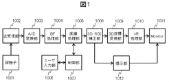
- FIG. 1 is a diagram illustrating an overall configuration of an ultrasonic diagnostic image generation apparatus according to Embodiment 1.
- FIG. It is a figure which shows the display screen for demonstrating a conventional method. It is a figure which shows the display screen for demonstrating the subject of this invention.
- FIG. 6 is a diagram illustrating an example of a configuration of a 3D-ROI correction unit according to the first embodiment.
- FIG. 6 is a diagram for explaining an ROI calculation unit of a 3D-ROI correction unit according to the first embodiment.
- FIG. It is a figure which shows an example of the energy map based on Example 1.
- FIG. It is a figure for demonstrating the minimum energy path
- FIG. 1 It is a figure for demonstrating the minimum energy path
- FIG. 6 is a diagram illustrating an example of a configuration of a 3D-ROI generation unit in an ultrasonic diagnostic image generation apparatus according to Embodiment 2.
- FIG. It is a figure which shows the example of a process of the validity determination part based on Example 2.
- FIG. It is a figure which shows the processing flow of the validity determination part based on Example 2.
- FIG. It is a figure which shows the whole structure of the ultrasonic diagnosing image generation apparatus of Example 3.
- FIG. It is a figure which shows an example of the volume data obtained by three-dimensional scanning of an ultrasonic diagnosing device. It is a figure for demonstrating 3D-ROI setting of an ultrasonic diagnosing device. It is a figure for demonstrating 3D-ROI setting of an ultrasonic diagnosing device.
- FIG. 23 shows an example of volume data of a fetus image 23003 obtained by three-dimensional scanning in the ultrasonic diagnostic apparatus.
- 24A and 24B show images of the tomographic planes 23001 and 23002 in FIG. 23, respectively.
- 23001 is called the Axial plane and 23002 is called the Sagittal plane.
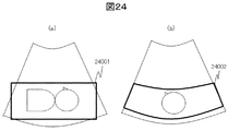
- ROI 24001 is set in the region of interest on the Axial plane
- the Sagittal plane is set with the same region 24002 as the size of the Axial ROI, and only those regions are set as 3D-ROI Get volume data.
- 3D-ROI has a three-dimensional structure as its name suggests, but using two-dimensional ROIs 24001 and 24002 on arbitrary Axial and Sagittal planes as shown in (a) and (b) of FIG.
- the volume data specified by the 3D-ROI as indicated by the thick line 25001 in FIG. 25 is obtained. That is, the ROI is set on the tomographic plane (basically determined by the Axial plane) where the fetus is displayed most appropriately, and 3D expansion is performed based on it.
- 3D-ROI can reduce volume data creation volume, improve real-time performance, and eliminate noise caused by floating objects and multiple reflections around the area of interest. Therefore, it is a very important function in 3D image display.
- FIG. 1 is a diagram illustrating a configuration example of an ultrasonic diagnostic image generation apparatus according to the first embodiment. According to the ultrasonic diagnostic image generation apparatus of the present embodiment, it is possible to obtain a high-quality 3D image display of a fetus, for example, with high robustness and more easily.
- the ultrasonic diagnostic image generation apparatus includes an ultrasonic transmission / reception unit connected to the probe 1001, an input unit for inputting an operator's operation, a display unit capable of displaying an image, and an ultrasonic transmission / reception unit.
- the tomographic image data of the fetus and the placenta is generated based on the signal acquired from the above, and in the state where the tomographic image data is displayed on the display unit, the region portion between the fetus and the placenta is determined according to the input from the input unit.
- a region-of-interest image processing unit a region-of-interest correction unit that corrects the region of interest using the region-of-interest and tomographic image data set by the operator, and determines the validity of the corrected region of interest;
- a presentation unit that presents the operator with the determination result of the validity of the region of interest, and generates a three-dimensional image of the fetus using the corrected region of interest.
- the present embodiment also includes an ultrasonic transmission / reception unit, a processing unit for processing a signal acquired from the ultrasonic transmission / reception unit, an input unit for input by an operator, and a display unit capable of displaying an image.
- An image generation method in a diagnostic image generation apparatus wherein a processing unit generates tomographic image data of a fetus and a placenta based on a signal acquired from an ultrasonic transmission / reception unit, and displays the tomographic image data on a display unit
- the region of interest including the region between the fetus and the placenta is set, and the region of interest is corrected using the region of interest set by the operator and the tomographic image data.
- the ultrasonic diagnostic image generation method for determining the validity of the corrected region of interest, displaying the determination result on the display unit, and generating the three-dimensional image of the fetus using the corrected region of interest is there.
- 1001 is a probe using an ultrasonic transducer for acquiring three-dimensional echo data
- 1002 is an ultrasonic transmission / reception unit that controls transmission pulses and amplifies reception echo signals
- 1003 is an analog / digital (A / D) conversion unit
- 1004 is a beam forming (BF) processing unit that performs phasing addition to bundle received echoes from many transducers
- 1005 is an RF from the beam forming processing unit 1004
- Image processing unit that generates tomographic image data by performing dynamic range compression, filter processing, and scan conversion processing on the signal
- 1006 is a user input unit
- 1007 is a 3D-ROI setting in the tomographic data generation of the image processing unit 1005 It is a control part which sets up the parameter for.
- the probe 1001 only needs to acquire 3D data, and any of a freehand method, a mechanical scan method, and a 2D array probe method may be used.
- a touch panel, a keyboard, a trackball, or the like can be used as the user input unit 1006 .
- the input from the user input unit 1006 by the operator is, for example, a point, a line, a rectangular area, or a combination thereof.
- Reference numeral 1008 denotes a 3D-ROI correction unit that is a region of interest correction unit
- 1009 denotes a 3D coordinate conversion unit that performs orthogonal three-dimensional coordinate conversion on the tomographic image data to create volume data
- 1010 denotes a 3D coordinate conversion unit 1009.
- Volume rendering (VR) processing unit that creates 3D ultrasound image that is two-dimensional projection data using volume data from, 1011 is a monitor
- 1012 is the validity for the correction result of 3D-ROI correction unit 1008 It is a presentation part.
- the 3D-ROI setting process performed by the user input unit 1006, the control unit 1007, and the image processing unit 1005 is disclosed in Patent Document 2, which is an already published application by the present applicant.
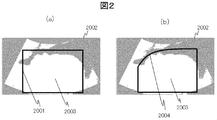
- the amniotic fluid area which is the area between the fetus and the placenta, is generally convex or concave on the rule of thumb, so the clipping plane that is the starting surface of the rendering process is generated by the Spline function. It realizes a smooth convex surface or concave surface and makes it possible to obtain an appropriate 3D display. That is, by introducing the concept of a curve into a function that can only be specified in a conventional rectangular area (straight line), the setting as shown in FIG. 3 can be made.
- FIG. 2 (a) schematically shows a conventional technique, and (b) schematically shows a technique described in Patent Document 2.
- 2002 and 2003 show the ultrasound diagnostic image and the images of the fetus and placenta displayed in the ultrasound diagnostic image, respectively, and 2001 and 2004 are generated by the rectangular area (straight line) and the Spline function, respectively. Region (curve) is shown.
- Region (curve) is shown.
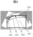
- FIG. 3 there are many cases where it is difficult to draw a boundary line clearly in the amniotic fluid region, which is the region between the placenta and the fetus, even with the Spline curve.
- reference numeral 3003 in the figure indicates a pixel having the lowest luminance value in a region 3002 surrounded by a dotted line including the Spline curve 3001.
- FIG. 4 shows an example of the configuration of the 3D-ROI correction unit 1008.
- 4001 is an ROI calculation unit that calculates an appropriate ROI based on information and data input from the image processing unit 1005, and 4002 is the validity of the calculated ROI.
- a validity determination unit 4003 is a ROI determination unit that determines the ROI based on the result determined by the validity determination unit 4002. As described above, these can be realized by program processing of a processing unit such as a CPU such as a PC.
- FIG. 5 shows an example of the configuration of the ROI calculation unit 4001.
- 5001 is Spline curve information and tomographic image data from the image processing unit 1005
- 5002 is a point on the received Spline curve that reliably detects a point that seems to be an amniotic fluid region that is the region between the fetus and the placenta.
- a start point detection unit, 5003 is an energy map generation unit that generates an energy map
- 5004 is a minimum energy route search unit that searches for a route that follows the energy minimum value of the energy map.
- the tomographic image data may be smoothed as preprocessing to remove a local low-brightness region.
- threshold processing is provided at this point, for example, when there is no luminance value below a predetermined threshold, this correction processing is not performed, and error processing that outputs the user's preset Spline curve 3001 itself is installed. You can also (not shown).
- the pixel value having the minimum luminance value is set as the minimum energy as the target pixel 6001. Is added to the pixel value.
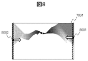
- This process is performed from the start point toward both ends of the image to generate an energy map 7001 as shown in FIG. FIG. 7 shows a region where the energy is lower as the luminance is lower.
- the luminance value is used as the energy value.
- the luminance value is not limited to the luminance value.
- luminance gradient information edge amount, entropy, likelihood, HoG, SaliencyMap, L1, L2 norm Etc., or combinations thereof may be used.
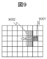
- the minimum energy path search unit 5004 in FIG. 5 detects pixels 8001 and 8002 that are the minimum value among the pixels at both ends as shown in FIG. 8 from the right (left) end of the energy map generated by the energy generation unit 5003. Start the search. In the search, as shown in FIG. 9, the pixel with the lowest energy among the left (right) side three pixels 9002 is selected with respect to the current pixel position 9001. This searches for the minimum energy path curve. In other words, the problem of drawing the border between the placenta and the fetus is reduced to the problem of dynamic programming.
- the search direction is limited to the three-pixel direction, so that calculation can be performed in linear time, and at the time of detecting the minimum energy path, one point on the user-set Spline curve must be set.
- the region-of-interest correction unit described as the 3D-ROI correction unit includes a start point detection unit that detects a pixel serving as a search start point from an area portion between the fetus and the placenta.
- An energy map generation unit that generates an energy map starting from the start point, a minimum energy path search unit that searches for a minimum energy path that follows the minimum value in the generated energy map, and validity of the searched minimum energy path And a validity determination unit for determining sex.
- the processing unit including the 3D-ROI correction unit detects the pixel that is the starting point of the search from the region between the fetus and the placenta, generates an energy map starting from the starting point, and is generated and recorded.
- the minimum energy path that traces the minimum value in the energy map is searched, and the validity of the searched minimum energy path is determined.
- the presentation unit displays the determination result on the display unit. In other words, the processing unit displays the determination result of the validity of the minimum energy path on the display unit.
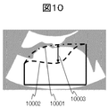
- the maximum distance 10003 between the Spline curve 10001 set by the user indicated by the alternate long and short dash line and the minimum energy path curve 10002 indicated by the broken line obtained in the configuration of the present embodiment is greater than or equal to the predetermined threshold value.
- the generated minimum energy path curve 10002 is not used, and the Spline curve 10001 set by the user is used as the ROI curve.
- TH2 may be treated as a variation allowable amount from the Spline curve set by the user.
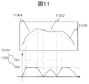
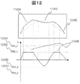
- TH1 and TH2 may be different values above and below the spline curve set by the user. That is, as shown in the lower part of FIG. 12, the upper threshold of the spline curve may be TH1_1 12001, TH2_1 12002, the lower threshold may be TH1_2 12003, TH2_2 12004, and the curve 12005 indicated by a solid line may be used.
- a curve 12006 indicated by a broken line in the lower part of FIG. 12 indicates the difference d from the generated minimum energy path curve 11004 and the Spline curve 11003 set by the user.
- the validity determination unit 4002 in FIG. 4 determines the validity based on the flowchart shown in FIG. 13, for example, in the ultrasonic diagnostic image generation apparatus of the present embodiment (S13001).
- the distance and difference between the user-set Spline curves 10001 and 11003 and the generated minimum energy path curves 10002 and 11004 are used as determination information.
- the method is not limited, and a method of measuring the similarity of curves using a variance value or the like, or a method of determining from the energy value itself may be used.
- the ROI determination unit 4003 generates a three-dimensional region using the ROI region in the cross-sectional image.
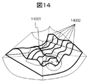
- An arbitrary plurality of points on the ROI curve (Axial ROI) are selected, and the region of interest curve (Sagittal ROI) with respect to the direction orthogonal to the ROI curve is generated in the same manner as Axial ROI.
- a 3D-ROI is generated by the Axial ROI and a plurality of Sagittal ROIs.
- each point on Axial ROI 14001 is used as a starting point, and Sagittal ROI 14002 is searched.
- the starting points on Axial ROI 14001 may be any interval, but interpolation using a Bezier surface is performed for points where ROI is not set. By using a Bezier curved surface, a smooth 3D-ROI can be generated.
- the presentation unit 1012 presents the determination result to the user using the display unit based on the determination result of the validity determination unit 4002 of the searched curve 15001. In other words, this determination result indicates whether or not the area surrounded by the searched curve 15001 appropriately includes the fetal area.
- the method of presenting validity for example, it may be possible to display the presence / absence of mark, shape, color, color of cross-sectional image frame, color of correction curve, message, or a combination thereof on the display screen of the monitor 1011. It is done. That is, as a method of presenting the determination result, the presence / absence of a mark, the color, the shape, or the shape of the frame of the region of interest, the color, the line type, the color of the cross-sectional image frame, a message, a numerical value, or a combination thereof is used. Use.
- the presenting position of the determination result is used within the cross-sectional image frame, outside the cross-sectional image frame, within the three-dimensional image frame, or a combination thereof.
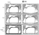
- FIG. 15 uses the difference in shape and color such as XX of the mark. 16 (a), (b), and (c) show the validity of the searched curve 16001, FIG. 16 (a) shows the difference in the color of the line of the curve 16001, and FIG. ) Is a difference in the line type of the curve 16001, and FIG.
- 16C is an example when the difference in color of the cross-sectional image frame line 16002 is used. Both are examples of presentation when the left side is valid and the right is invalid.
- the present invention is not limited to the examples in FIG. 16, and the colors and line types of curves and cross-sectional image frame lines can be appropriately combined and presented so that the user can easily determine the validity.
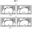
- FIG. 17 (A) and (b) in FIG. 17 show an example of validity
- FIG. 17 (a) shows an example in which a message 17001 is presented
- FIG. 17 (b) shows an example in which a numerical value 17002 is displayed. Both are examples of presentation when the left side is valid and the right is invalid.
- presenting a message or a numerical value there is an advantage that the change is easy to understand for the user and no prior learning is required, but the area required for display is large, and since it is a sentence, it is difficult to understand intuitively.
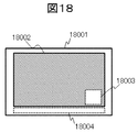
- Fig. 18 shows an example of the validity presentation position.
- 18001 is a display range of the monitor 1011 in FIG. 1
- 18002 is a tomographic image or 3D image
- 18003 and 18004 are examples of appropriate presentation positions.
- Use of a tomographic image or 3D image display frame 18003, image display frame outside 18004, other lamps (not shown), and combinations thereof are conceivable.
- the validity presentation position is the lower right in the image and the lower outer portion of the image, but it is of course not limited to this. When the number of displayed images changes, the determination result may be presented for each image, or only one place may be presented as a representative.
- a more suitable 3D fetal image can be acquired.
- the user can easily and intuitively understand whether or not the search is successful, and the operability is improved.
- Embodiment 2 is an ultrasonic diagnostic image generation apparatus that allows a user to understand what action should be taken next when ROI is not appropriately corrected, and to more easily set the ROI.
- a guide message generation unit that generates a guide message for the operator based on the determination result of the 3D-ROI correction unit that is a region of interest correction unit, and the presentation unit presents the validity and the guide message to the operator.
- generation part is an Example of an ultrasonic diagnostic image generation apparatus using the criterion of a validity determination part.
- the ultrasonic diagnostic image generation apparatus according to the present embodiment generates a guide message for the operator based on the determination result, and displays the determination result and the guide message on the display unit.
- FIG. This embodiment is different from the first embodiment in that a guide message generation unit is newly provided in the 3D-ROI correction unit 1008.
- this guide message generation unit can be realized by program processing of a processing unit such as a CPU of the PC, like the 3D-ROI correction unit 1008 of the first embodiment.
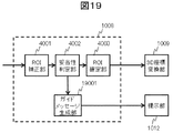
- FIG. 19 is a diagram illustrating a configuration example of the 3D-ROI correction unit 1008 in the ultrasonic diagnostic video processing system according to the second embodiment.
- the validity determination unit 4002 transmits the determination result and the determination criterion to the guide message generation unit 19001.
- the guide message generation unit 19001 generates a specific guide message based on the received determination result and determination criterion, that is, the next action plan of the user.
- the presentation unit 1012 presents the guide message generated by the guide message generation unit 19001 on the monitor 1011 in addition to the determination result described above.
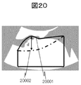
- the validity determination unit 4002 generates a guide message when it is determined that there is no validity because the searched curve 20001 exceeds the upper threshold shown in FIG. 12, for example, as shown in FIG.
- the result of determination (no validity) is transmitted to the part 19001 and the fact that the upper threshold is exceeded is determined as the determination reason and determination criterion.
- the guide message generation unit 19001 is based on the determination reason “upper threshold exceeded” from the validity determination unit 4002, “the Spline curve 20002 set by the user may be set too low for the fetus” Can be generated.
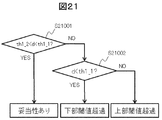
- FIG. 21 is a determination flow of the validity determination unit 4002 in the present embodiment.
- the difference d between the generated minimum energy path curve 20002 indicated by the solid line and the Spline curve 20001 set by the user indicated by the alternate long and short dash line is between the lower threshold TH1_2 and the upper threshold TH1_1. It is determined whether or not there is (S21001). If YES, “valid” is determined. If NO, it is determined whether or not the difference d is less than the upper threshold TH1_1 (S21002). , “Lower threshold exceeded” and “upper threshold exceeded”.
- the guide message generation unit 19001 may generate a guide message using a different determination criterion without using the same determination criterion as that of the validity determination unit 4002. For example, when the above “upper threshold is exceeded”, the total energy of the route is added as a criterion. If the total energy is larger than the predetermined value, it is determined that the search itself has failed, and a different guide message such as “Please input a different tomographic image” is generated. In addition to the energy sum, a dispersion value or the like may be used.
- Example 3 is an example of an ultrasonic diagnostic video processing system in which a user can view the validity determination result and the guide message without giving anxiety to the patient.
- FIG. 22 is a diagram illustrating a configuration example of the ultrasonic diagnostic image generation apparatus according to the present embodiment.
- This embodiment is different from the second embodiment in that the validity determination result and the guide message are displayed on the second monitor 22001 which is the second display unit. That is, a second display unit different from the monitor 1011 as a display unit is provided, and this second display unit displays validity and a guide message.
- the presentation regarding validity in the second embodiment is presented on the second monitor 22001 which is the second display unit that can be browsed only by the user.
- the second monitor 22001 a dedicated display terminal, a tablet, a smartphone, or the like can be considered.
- the second monitor 22001 may display a validity determination result, a guide message, a tomographic image, a 3D image, a correction curve determined to be invalid, and the like.
- the user can browse the validity determination result and the correction plan without giving the patient anxiety.
- this invention is not limited to an above-described Example, Various modifications are included.
- the above-described embodiments have been described in detail for better understanding of the present invention, and are not necessarily limited to those having all the configurations described.
- a part of the configuration of one embodiment can be replaced with the configuration of another embodiment, and the configuration of another embodiment can be added to the configuration of one embodiment.
Landscapes
- Health & Medical Sciences (AREA)
- Life Sciences & Earth Sciences (AREA)
- Engineering & Computer Science (AREA)
- Medical Informatics (AREA)
- Surgery (AREA)
- Pathology (AREA)
- Radiology & Medical Imaging (AREA)
- Biophysics (AREA)
- Biomedical Technology (AREA)
- Heart & Thoracic Surgery (AREA)
- Physics & Mathematics (AREA)
- Molecular Biology (AREA)
- Nuclear Medicine, Radiotherapy & Molecular Imaging (AREA)
- Animal Behavior & Ethology (AREA)
- General Health & Medical Sciences (AREA)
- Public Health (AREA)
- Veterinary Medicine (AREA)
- Gynecology & Obstetrics (AREA)
- Pregnancy & Childbirth (AREA)
- Computer Graphics (AREA)
- General Engineering & Computer Science (AREA)
- Computer Vision & Pattern Recognition (AREA)
- Ultra Sonic Daignosis Equipment (AREA)
Priority Applications (2)
| Application Number | Priority Date | Filing Date | Title |
|---|---|---|---|
| CN201580039063.0A CN106659480B (zh) | 2014-08-22 | 2015-04-17 | 超声波诊断图像生成装置以及方法 |
| US15/320,299 US10433815B2 (en) | 2014-08-22 | 2015-04-17 | Ultrasound diagnostic image generating device and method |
Applications Claiming Priority (2)
| Application Number | Priority Date | Filing Date | Title |
|---|---|---|---|
| JP2014169438A JP6196951B2 (ja) | 2014-08-22 | 2014-08-22 | 超音波診断画像生成装置、及び方法 |
| JP2014-169438 | 2014-08-22 |
Publications (1)
| Publication Number | Publication Date |
|---|---|
| WO2016027510A1 true WO2016027510A1 (ja) | 2016-02-25 |
Family
ID=55350465
Family Applications (1)
| Application Number | Title | Priority Date | Filing Date |
|---|---|---|---|
| PCT/JP2015/061794 Ceased WO2016027510A1 (ja) | 2014-08-22 | 2015-04-17 | 超音波診断画像生成装置、及び方法 |
Country Status (4)
| Country | Link |
|---|---|
| US (1) | US10433815B2 (enExample) |
| JP (1) | JP6196951B2 (enExample) |
| CN (1) | CN106659480B (enExample) |
| WO (1) | WO2016027510A1 (enExample) |
Families Citing this family (10)
| Publication number | Priority date | Publication date | Assignee | Title |
|---|---|---|---|---|
| KR102545007B1 (ko) * | 2015-10-20 | 2023-06-20 | 삼성메디슨 주식회사 | 초음파 영상장치 및 그 제어방법 |
| US11521363B2 (en) * | 2017-05-12 | 2022-12-06 | Shenzhen Mindray Bio-Medical Electronics Co., Ltd. | Ultrasonic device, and method and system for transforming display of three-dimensional ultrasonic image thereof |
| WO2018236195A1 (ko) * | 2017-06-23 | 2018-12-27 | 울산대학교 산학협력단 | 초음파 영상 처리 방법 |
| KR102027974B1 (ko) * | 2018-08-31 | 2019-10-04 | 길재소프트 주식회사 | 딥 러닝 기반 가상현실 3d 태아 모델 제공 시스템 및 방법 |
| CN112654301A (zh) * | 2018-12-28 | 2021-04-13 | 深圳迈瑞生物医疗电子股份有限公司 | 一种脊柱的成像方法以及超声成像系统 |
| JP7269778B2 (ja) * | 2019-04-04 | 2023-05-09 | 富士フイルムヘルスケア株式会社 | 超音波撮像装置、および、画像処理装置 |
| KR102224627B1 (ko) * | 2019-04-08 | 2021-03-09 | 울산대학교 산학협력단 | 임신 1분기 초음파 이미지 분석 방법 및 장치 |
| JP7424003B2 (ja) * | 2019-11-20 | 2024-01-30 | コニカミノルタ株式会社 | 医用画像表示装置、領域表示方法及び領域表示プログラム |
| US11457891B2 (en) * | 2020-08-17 | 2022-10-04 | Clarius Mobile Health Corp. | Method and system for defining cut lines to generate a 3D fetal representation |
| KR20250118071A (ko) * | 2024-01-29 | 2025-08-05 | 삼성메디슨 주식회사 | 초음파 이미지의 품질을 향상시키는 방법 및 그에 따른 초음파 영상 장치 |
Citations (4)
| Publication number | Priority date | Publication date | Assignee | Title |
|---|---|---|---|---|
| JP2006231035A (ja) * | 2005-01-26 | 2006-09-07 | Toshiba Corp | 超音波診断装置及び超音波診断装置の制御プログラム |
| JP2011083439A (ja) * | 2009-10-15 | 2011-04-28 | Aloka Co Ltd | 超音波ボリュームデータ処理装置 |
| WO2013027526A1 (ja) * | 2011-08-19 | 2013-02-28 | 株式会社 日立メディコ | 医用画像装置及び医用画像構成方法 |
| JP2013141515A (ja) * | 2012-01-11 | 2013-07-22 | Hitachi Aloka Medical Ltd | 医用画像装置及び医用画像構成方法 |
Family Cites Families (8)
| Publication number | Priority date | Publication date | Assignee | Title |
|---|---|---|---|---|
| KR100686289B1 (ko) | 2004-04-01 | 2007-02-23 | 주식회사 메디슨 | 대상체 영상의 윤곽내 볼륨 데이터를 이용하는 3차원초음파 영상 형성 장치 및 방법 |
| JP5209213B2 (ja) * | 2006-01-10 | 2013-06-12 | 株式会社東芝 | 超音波診断装置及び超音波画像生成プログラム |
| WO2008081558A1 (ja) * | 2006-12-28 | 2008-07-10 | Kabushiki Kaisha Toshiba | 超音波画像取得装置、及び超音波画像の取得方法 |
| JP5243845B2 (ja) * | 2008-05-22 | 2013-07-24 | 日立アロカメディカル株式会社 | ボリュームデータ処理装置 |
| EP2444939A1 (en) * | 2009-10-15 | 2012-04-25 | Hitachi Aloka Medical, Ltd. | Ultrasonic volume data processing device |
| JP2012010965A (ja) | 2010-06-30 | 2012-01-19 | Toshiba Corp | 超音波診断装置および超音波診断装置の制御方法 |
| US9392995B2 (en) * | 2012-07-25 | 2016-07-19 | General Electric Company | Ultrasound imaging system and method |
| CN103034979B (zh) * | 2012-11-30 | 2015-03-25 | 声泰特(成都)科技有限公司 | 一种超声图像清晰度提升方法 |
-
2014
- 2014-08-22 JP JP2014169438A patent/JP6196951B2/ja active Active
-
2015
- 2015-04-17 US US15/320,299 patent/US10433815B2/en active Active
- 2015-04-17 WO PCT/JP2015/061794 patent/WO2016027510A1/ja not_active Ceased
- 2015-04-17 CN CN201580039063.0A patent/CN106659480B/zh active Active
Patent Citations (4)
| Publication number | Priority date | Publication date | Assignee | Title |
|---|---|---|---|---|
| JP2006231035A (ja) * | 2005-01-26 | 2006-09-07 | Toshiba Corp | 超音波診断装置及び超音波診断装置の制御プログラム |
| JP2011083439A (ja) * | 2009-10-15 | 2011-04-28 | Aloka Co Ltd | 超音波ボリュームデータ処理装置 |
| WO2013027526A1 (ja) * | 2011-08-19 | 2013-02-28 | 株式会社 日立メディコ | 医用画像装置及び医用画像構成方法 |
| JP2013141515A (ja) * | 2012-01-11 | 2013-07-22 | Hitachi Aloka Medical Ltd | 医用画像装置及び医用画像構成方法 |
Also Published As
| Publication number | Publication date |
|---|---|
| US10433815B2 (en) | 2019-10-08 |
| JP2016043039A (ja) | 2016-04-04 |
| JP6196951B2 (ja) | 2017-09-13 |
| US20170251999A1 (en) | 2017-09-07 |
| CN106659480B (zh) | 2019-09-24 |
| CN106659480A (zh) | 2017-05-10 |
Similar Documents
| Publication | Publication Date | Title |
|---|---|---|
| JP6196951B2 (ja) | 超音波診断画像生成装置、及び方法 | |
| US10347035B2 (en) | Diagnostic image generation apparatus and diagnostic image generation method | |
| CN115486877B (zh) | 一种超声设备及其显示三维超声图像的方法 | |
| JP6490809B2 (ja) | 超音波診断装置、及び画像処理方法 | |
| US10743844B2 (en) | Ultrasound imaging apparatus | |
| US20120065499A1 (en) | Medical image diagnosis device and region-of-interest setting method therefore | |
| EP2302414A2 (en) | Ultrasound system and method of performing measurement on three-dimensional ultrasound image | |
| JP6390193B2 (ja) | 超音波診断装置、超音波診断装置の制御方法、および、プログラム | |
| JP6097452B2 (ja) | 超音波撮像システム及び超音波撮像方法 | |
| JP6467221B2 (ja) | 画像処理装置および方法 | |
| US9767562B2 (en) | Image processing apparatus, image processing method and storage medium | |
| JP5002260B2 (ja) | 医用画像診断装置 | |
| JP5138369B2 (ja) | 超音波診断装置及びその画像処理方法 | |
| KR20120046539A (ko) | 바디 마크를 제공하는 초음파 시스템 및 방법 | |
| CN112654301A (zh) | 一种脊柱的成像方法以及超声成像系统 | |
| JP5642420B2 (ja) | ボリュームデータをレンダリングする超音波システムおよび方法 | |
| JP6204544B2 (ja) | 診断画像生成装置 | |
| US20210093298A1 (en) | Methods and apparatuses for providing feedback for positioning an ultrasound device | |
| JP5959880B2 (ja) | 超音波診断装置 | |
| JP5645742B2 (ja) | 超音波診断装置及びその制御プログラム | |
| KR101024857B1 (ko) | 3차원 초음파 영상에 컬러 모델링 처리를 수행하는 초음파 시스템 및 방법 | |
| JP2017195913A (ja) | 超音波診断装置 |
Legal Events
| Date | Code | Title | Description |
|---|---|---|---|
| 121 | Ep: the epo has been informed by wipo that ep was designated in this application |
Ref document number: 15833929 Country of ref document: EP Kind code of ref document: A1 |
|
| WWE | Wipo information: entry into national phase |
Ref document number: 15320299 Country of ref document: US |
|
| NENP | Non-entry into the national phase |
Ref country code: DE |
|
| 122 | Ep: pct application non-entry in european phase |
Ref document number: 15833929 Country of ref document: EP Kind code of ref document: A1 |