WO2016021486A1 - タイヤホイール用搬送材 - Google Patents
タイヤホイール用搬送材 Download PDFInfo
- Publication number
- WO2016021486A1 WO2016021486A1 PCT/JP2015/071754 JP2015071754W WO2016021486A1 WO 2016021486 A1 WO2016021486 A1 WO 2016021486A1 JP 2015071754 W JP2015071754 W JP 2015071754W WO 2016021486 A1 WO2016021486 A1 WO 2016021486A1
- Authority
- WO
- WIPO (PCT)
- Prior art keywords
- tire
- pallet
- tire wheels
- wheels
- wheel
- Prior art date
- Legal status (The legal status is an assumption and is not a legal conclusion. Google has not performed a legal analysis and makes no representation as to the accuracy of the status listed.)
- Ceased
Links
Images






Classifications
-
- B—PERFORMING OPERATIONS; TRANSPORTING
- B65—CONVEYING; PACKING; STORING; HANDLING THIN OR FILAMENTARY MATERIAL
- B65D—CONTAINERS FOR STORAGE OR TRANSPORT OF ARTICLES OR MATERIALS, e.g. BAGS, BARRELS, BOTTLES, BOXES, CANS, CARTONS, CRATES, DRUMS, JARS, TANKS, HOPPERS, FORWARDING CONTAINERS; ACCESSORIES, CLOSURES, OR FITTINGS THEREFOR; PACKAGING ELEMENTS; PACKAGES
- B65D19/00—Pallets or like platforms, with or without side walls, for supporting loads to be lifted or lowered
- B65D19/38—Details or accessories
- B65D19/44—Elements or devices for locating articles on platforms
-
- B—PERFORMING OPERATIONS; TRANSPORTING
- B65—CONVEYING; PACKING; STORING; HANDLING THIN OR FILAMENTARY MATERIAL
- B65D—CONTAINERS FOR STORAGE OR TRANSPORT OF ARTICLES OR MATERIALS, e.g. BAGS, BARRELS, BOTTLES, BOXES, CANS, CARTONS, CRATES, DRUMS, JARS, TANKS, HOPPERS, FORWARDING CONTAINERS; ACCESSORIES, CLOSURES, OR FITTINGS THEREFOR; PACKAGING ELEMENTS; PACKAGES
- B65D19/00—Pallets or like platforms, with or without side walls, for supporting loads to be lifted or lowered
- B65D19/0004—Rigid pallets without side walls
- B65D19/0006—Rigid pallets without side walls the load supporting surface being made of a single element
- B65D19/003—Rigid pallets without side walls the load supporting surface being made of a single element forming discontinuous or non-planar contact surfaces
- B65D19/0032—Rigid pallets without side walls the load supporting surface being made of a single element forming discontinuous or non-planar contact surfaces the base surface being made of a single element
- B65D19/0036—Rigid pallets without side walls the load supporting surface being made of a single element forming discontinuous or non-planar contact surfaces the base surface being made of a single element forming discontinuous or non-planar contact surfaces
- B65D19/004—Rigid pallets without side walls the load supporting surface being made of a single element forming discontinuous or non-planar contact surfaces the base surface being made of a single element forming discontinuous or non-planar contact surfaces and each contact surface having a discrete foot-like shape
-
- B—PERFORMING OPERATIONS; TRANSPORTING
- B65—CONVEYING; PACKING; STORING; HANDLING THIN OR FILAMENTARY MATERIAL
- B65D—CONTAINERS FOR STORAGE OR TRANSPORT OF ARTICLES OR MATERIALS, e.g. BAGS, BARRELS, BOTTLES, BOXES, CANS, CARTONS, CRATES, DRUMS, JARS, TANKS, HOPPERS, FORWARDING CONTAINERS; ACCESSORIES, CLOSURES, OR FITTINGS THEREFOR; PACKAGING ELEMENTS; PACKAGES
- B65D71/00—Bundles of articles held together by packaging elements for convenience of storage or transport, e.g. portable segregating carrier for plural receptacles such as beer cans or pop bottles; Bales of material
- B65D71/0088—Palletisable loads, i.e. loads intended to be transported by means of a fork-lift truck
- B65D71/0092—Palletisable loads, i.e. loads intended to be transported by means of a fork-lift truck provided with one or more rigid supports, at least one dimension of the supports corresponding to a dimension of the load, e.g. skids
- B65D71/0096—Palletisable loads, i.e. loads intended to be transported by means of a fork-lift truck provided with one or more rigid supports, at least one dimension of the supports corresponding to a dimension of the load, e.g. skids the dimensions of the supports corresponding to the periphery of the load, e.g. pallets
-
- B—PERFORMING OPERATIONS; TRANSPORTING
- B65—CONVEYING; PACKING; STORING; HANDLING THIN OR FILAMENTARY MATERIAL
- B65D—CONTAINERS FOR STORAGE OR TRANSPORT OF ARTICLES OR MATERIALS, e.g. BAGS, BARRELS, BOTTLES, BOXES, CANS, CARTONS, CRATES, DRUMS, JARS, TANKS, HOPPERS, FORWARDING CONTAINERS; ACCESSORIES, CLOSURES, OR FITTINGS THEREFOR; PACKAGING ELEMENTS; PACKAGES
- B65D85/00—Containers, packaging elements or packages, specially adapted for particular articles or materials
- B65D85/02—Containers, packaging elements or packages, specially adapted for particular articles or materials for annular articles
- B65D85/06—Containers, packaging elements or packages, specially adapted for particular articles or materials for annular articles for tyres
-
- B—PERFORMING OPERATIONS; TRANSPORTING
- B65—CONVEYING; PACKING; STORING; HANDLING THIN OR FILAMENTARY MATERIAL
- B65D—CONTAINERS FOR STORAGE OR TRANSPORT OF ARTICLES OR MATERIALS, e.g. BAGS, BARRELS, BOTTLES, BOXES, CANS, CARTONS, CRATES, DRUMS, JARS, TANKS, HOPPERS, FORWARDING CONTAINERS; ACCESSORIES, CLOSURES, OR FITTINGS THEREFOR; PACKAGING ELEMENTS; PACKAGES
- B65D2519/00—Pallets or like platforms, with or without side walls, for supporting loads to be lifted or lowered
- B65D2519/00004—Details relating to pallets
- B65D2519/00736—Details
- B65D2519/0081—Elements or devices for locating articles
- B65D2519/00815—Elements or devices for locating articles on the pallet
-
- B—PERFORMING OPERATIONS; TRANSPORTING
- B65—CONVEYING; PACKING; STORING; HANDLING THIN OR FILAMENTARY MATERIAL
- B65D—CONTAINERS FOR STORAGE OR TRANSPORT OF ARTICLES OR MATERIALS, e.g. BAGS, BARRELS, BOTTLES, BOXES, CANS, CARTONS, CRATES, DRUMS, JARS, TANKS, HOPPERS, FORWARDING CONTAINERS; ACCESSORIES, CLOSURES, OR FITTINGS THEREFOR; PACKAGING ELEMENTS; PACKAGES
- B65D2519/00—Pallets or like platforms, with or without side walls, for supporting loads to be lifted or lowered
- B65D2519/00004—Details relating to pallets
- B65D2519/00736—Details
- B65D2519/00935—Details with special means for nesting or stacking
- B65D2519/00955—Details with special means for nesting or stacking stackable
- B65D2519/00965—Details with special means for nesting or stacking stackable when loaded
Definitions
- the present invention relates to a tire wheel carrier.
- Patent Document 1 discloses a pallet in which an annular groove corresponding to a plurality of types of automobile wheels having different diameters is provided on a mounting surface.
- a plurality of annular grooves are formed for each diameter in a state of being overlapped with other annular grooves in a planar manner.
- the pallet of Patent Document 1 when a wheel is transported, the wheel is fitted into an annular groove corresponding to the diameter, thereby preventing the wheel from being displaced and transporting and storing a plurality of types of wheels having different sizes. It corresponds to.
- Patent Document 2 discloses a technique in which each stage of a tire wheel stacked on a pallet is sandwiched between two support fixing members that can prevent the tire wheel from moving horizontally. According to this technology, a plurality of tire wheels can be stacked on a pallet while preventing horizontal movement of the tire wheel.
- the present invention has been made in view of such circumstances, and an object thereof is to form a plurality of tire wheels stacked on one pallet as one unit and stably stack such units in a plurality of stages. Accordingly, it is an object of the present invention to provide a tire wheel carrier that can transport and store more tire wheels more efficiently.
- One aspect according to the present invention is a tire wheel transport material, the mounting surface on which a plurality of tire wheels in a laid-down state are arranged, the mounting surface, and the plurality of tire wheels
- a pallet having a plurality of fitting parts to which the lower peripheral edge of the rim is fitted, and interposed between the upper and lower stages of the plurality of tire wheels stacked in a plurality of stages on the mounting surface of the pallet,
- a partition plate that prevents lateral displacement of the plurality of upper tire wheels and the plurality of lower tire wheels, and the upper peripheral edge of the rim of the plurality of tire wheels that covers the plurality of upper tire wheels
- a cover body having a plurality of wheel positioning recesses on the lower surface, and the pallet has a plurality of legs projecting downward on the lower surface, and the pallet
- the lid body is formed on the upper surface of the pallet so that a plurality of units can be stacked with the plurality of tire wheels, the partition plates, and the
- the lid is formed of a hollow resin molded body integrally having a double wall structure having an upper wall and a lower wall, and the plurality of leg positioning recesses are
- the upper surface wall may be provided so as to be recessed on the lower surface wall side, and the plurality of wheel positioning recesses may be provided on the lower surface wall so as to be recessed on the upper surface wall side.
- the wheel positioning recess may be a groove corresponding to the upper peripheral edge of the rim.
- a plurality of stages of tire wheels stacked on one pallet can be used as one unit, and such units can be stably stacked in a plurality of stages, thereby increasing the number of tire wheels. It is possible to provide a transport material for a tire wheel that can be efficiently transported and stored.
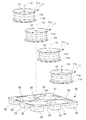
- FIG. 1A is a perspective view seen from an obliquely upper side
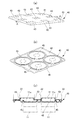
- FIG. 2A is A sectional view.
- work process which mounts a tire wheel on a pallet is a figure explaining the operation
- work process which mounts a partition plate on a tire wheel is a figure explaining the operation
- the tire wheel transport material 10 is a material for transporting and storing a tire wheel 11 such as an aluminum wheel, and a plurality of tire wheels 11 are in a laid state, that is, a shaft hole of the tire wheel 11.
- a pallet 20 placed in a state where the 12 axis lines 13 are directed in the vertical direction (see FIG. 2), and a partition plate interposed between the upper and lower stages of the plurality of tire wheels 11 stacked on the pallet 20 in a plurality of stages. 30 and a lid 40 covering the plurality of uppermost tire wheels 11.
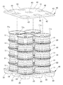
- a single unit 50 can be configured by the pallet 20, the plurality of tire wheels 11 stacked on the pallet 20, the plurality of partition plates 30, and the lid body 40. Further, another unit 50A can be stacked in a plurality of stages on the lid 40 of one unit 50.
- FIG. 1 illustrates two units 50 and 50A stacked in two stages.
- the pallet 20 is made of synthetic resin, and the planar shape is formed in a substantially square shape.
- the pallet 20 has a placement surface 21 on which a plurality (four in this example) of tire wheels 11 are placed side by side.
- a plurality of leg portions 22 projecting downward are provided on the lower surface of the pallet 20.
- Each leg 22 is formed by a recess that is recessed downward from the placement surface 21 side.
- nine leg portions 22 are arranged in a lattice point on the lower surface of the substantially rectangular pallet 20.
- a fork insertion portion 23 into which a fork (claw) of a forklift is inserted is formed in a separation portion between two adjacent leg portions 22.
- the mounting surface 21 is provided with a plurality of fitting portions 25 into which the lower peripheral edge portions 11d of the rims 11a of the plurality of tire wheels 11 are fitted.
- the plurality of fitting portions 25 are annular groove portions, and are formed in portions excluding the leg portions 22 so as not to overlap each other on the placement surface 21.
- the partition plate 30 is formed in a substantially square shape in plan view, and has a plurality of annular lower fitting portions 31 corresponding to the plurality of tire wheels 11 arranged on the pallet 20.
- Each lower fitting portion 31 is an annular groove that is recessed from the lower surface side to the upper surface side of the partition plate 30, and can be fitted to the upper peripheral edge portion 11 u of the rim 11 a of each tire wheel 11.
- the partition plate 30 is provided with a plurality of annular upper fitting portions 32 concentrically with the lower fitting portion 31.
- Each upper fitting portion 32 is an annular groove portion that is recessed from the upper surface side to the lower surface side of the partition plate 30, and can be fitted to the lower peripheral edge portion 11 d of the rim 11 a of the tire wheel 11 placed on the partition plate 30. It is.
- the lid body 40 is a hollow resin molded body integrally having a double wall structure composed of an upper surface wall 41 and a lower surface wall 42, and the planar shape is formed in a substantially square shape.
- the molding method of this resin molding is arbitrary, it is possible to form a hollow resin molding (cover body 40) by blow molding, for example.
- the molding material for the lid 40 can be a polyolefin-based resin typified by polyethylene or polypropylene.
- the upper surface wall 41 is provided with a plurality of leg positioning recesses 43. Further, as shown in FIG. 4B, the lower surface wall 42 is provided with a plurality of wheel positioning recesses 45.
- each of the plurality of leg positioning recesses 43 is formed to be recessed from the upper surface wall 41 side to the lower surface wall 42 side, and the leg portion 22 of the pallet 20 is fitted from above.
- each wheel positioning recess 45 is an annular groove recessed from the lower surface wall 42 side to the upper surface wall 41 side, and corresponds to the upper peripheral edge portion 11u of each uppermost tire wheel 11 in the unit 50 (see FIG. 1). It can be fitted to the upper peripheral edge 11u.
- each tire wheel 11 in pallet 20 is arranged in a regular position, and a lateral position shift of each tire wheel 11 is prevented.
- the partition plate 30 is placed on the plurality of tire wheels 11 arranged on the pallet 20 from above. At this time, the partition plate 30 is mounted so that each of the plurality of lower fitting portions 31 of the partition plate 30 is fitted to the upper peripheral edge portion 11u of the rim 11a.
- a plurality of tire wheels 11 are placed side by side on the partition plate 30 in a state of being laid down.
- the lower peripheral edge portion 11d of the rim 11a is fitted to the upper fitting portion 32 of the partition plate 30.
- the lower fitting portion 31 is fitted to the plurality of lower tire wheels 11, and the upper fitting portion 32 is fitted to the plurality of upper tire wheels 11. 11 and upper tire wheel 11 are prevented from being displaced in the lateral direction.
- a partition plate 30 is further placed on the plurality of upper tire wheels 11 from above, and a plurality of tire wheels 11 corresponding to a predetermined number of steps (in this example, five steps) are further divided. They are stacked via the plate 30. Then, the lid body 40 is put on the plurality of uppermost tire wheels 11. At this time, the lid body 40 is covered so that each of the plurality of wheel positioning recesses 45 (see FIG. 4B) of the lid body 40 is fitted to the upper peripheral edge portion 11u of the rim 11a.
- the stretch film 15 is wound around the entire circumference of the tire wheel 11 stacked in a plurality of stages, and the pallet 20 and the lid body 40 are bound by the binding band 16, and the stacked tire wheel 11 is stacked. Is fixed between the pallet 20 and the lid 40. Thereby, one unit 50 is comprised by the pallet 20, the tire wheel 11 piled up in multiple steps, the partition plate 30, and the cover body 40. As shown in FIG. 9, the stretch film 15 is wound around the entire circumference of the tire wheel 11 stacked in a plurality of stages, and the pallet 20 and the lid body 40 are bound by the binding band 16, and the stacked tire wheel 11 is stacked. Is fixed between the pallet 20 and the lid 40. Thereby, one unit 50 is comprised by the pallet 20, the tire wheel 11 piled up in multiple steps, the partition plate 30, and the cover body 40. As shown in FIG.
- another unit 50 ⁇ / b> A is stacked on one unit 50.
- the leg portion 22 of the pallet 20 of another unit 50 ⁇ / b> A is fitted into the leg portion positioning recess 43 of the lid body 40 of one unit 50.
- a plurality of units 50 and 50A stacked in a plurality of stages can be obtained.
- the leg positioning recess 43 is provided on the upper surface of the lid 40, and the leg 22 of the pallet 20 of another unit 50 ⁇ / b> A is fitted into the leg positioning recess 43.
- the plurality of units 50 and 50A can be stably stacked. As a result, more tire wheels 11 can be transported and stored more efficiently.
- FIG. 11 (a) in the pallet 20 according to this modification, six tire wheels 11 can be placed, and six fitting portions 25 are provided on the placement surface 21. Moreover, as shown in FIG.11 (b), the fitting recessed part 22a with a circular cross section is provided in the bottom face of each leg part 22 of this pallet 20. As shown in FIG. 11 (a), in the pallet 20 according to this modification, six tire wheels 11 can be placed, and six fitting portions 25 are provided on the placement surface 21. Moreover, as shown in FIG.11 (b), the fitting recessed part 22a with a circular cross section is provided in the bottom face of each leg part 22 of this pallet 20. As shown in FIG.
- a protrusion 43a protruding upward is provided at the center of the leg positioning recess 43 of the lid 40.
- the protrusion 43a is a convex portion having a circular cross section that can be fitted into the fitting concave portion 22a of the leg portion 22 (see FIG. 11B).
- six wheel positioning recesses 45 corresponding to the six tire wheels 11 are provided on the lower surface wall 42 of the lid body 40.
- the fitting recess 22a of the leg 22 is the leg. Since the protrusion 43a of the positioning recess 43 can be fitted, the fitting strength between the leg portion 22 and the leg positioning recess 43 can be further increased. Thereby, a plurality of units can be stacked more stably.
- SYMBOLS 10 Tire wheel conveyance material, 11 ... Tire wheel, 11a ... Rim, 11u ... Upper peripheral part, 11d ... Lower peripheral part, 20 ... Pallet, 21 ... Mounting surface, 22 ... Leg part, 23 ... Fork insertion part 25 ... fitting part, 30 ... partition plate, 31 ... lower fitting part, 32 ... upper fitting part, 40 ... lid body, 41 ... upper surface wall (upper surface), 42 ... lower surface wall (lower surface), 43 ... Leg positioning recess, 45 ... wheel positioning recess, 50 ... unit, 50A ... another unit
Landscapes
- Engineering & Computer Science (AREA)
- Mechanical Engineering (AREA)
- Packaging Of Annular Or Rod-Shaped Articles, Wearing Apparel, Cassettes, Or The Like (AREA)
- Pallets (AREA)
Abstract
タイヤホイール用搬送材(10)は、横倒し状態の複数のタイヤホイール(11)が並べられる載置面(21)に設けられ、複数のタイヤホイール(11)のリムの下側周縁部が嵌合される複数の嵌合部(25)を有するパレット(20)と、載置面(21)に複数段積み上げられる複数のタイヤホイール(11)の上段と下段との間に介在し、横方向の位置ずれを防止する仕切り板(30)と、最上段の複数のタイヤホイール(11)を覆うとともに複数のタイヤホイール(11)のリムの上側周縁部が嵌合される複数のホイール位置決め用凹部(45)を下面に有する蓋体(40)と、を備え、パレット(20)が、その下面に、下方に突出する複数の脚部(22)を有し、複数のユニット(50,50A)が積み上げ可能であるように、蓋体(40)が、その上面に、パレット(20)の複数の脚部(22)のそれぞれに対応する複数の脚部位置決め用凹部(43)を有する。
Description
本発明は、タイヤホイール用搬送材に関する。
従来、アルミホイールなどのタイヤホイールを搬送する各種の搬送材が提案されている(例えば、特許文献1参照)。
特許文献1には、径の異なる複数種の自動車用ホイールに対応した環状の溝を載置面に設けたパレットが開示される。このパレットでは、環状の溝を、他の環状の溝と平面的に重ね合わせた状態にてそれぞれの径毎に複数形成する。特許文献1のパレットによれば、ホイールの運搬に際して、径に応じた環状の溝にホイールを嵌め込むことで、ホイールの位置ずれを防止するとともに、大きさの異なる複数種のホイールの運搬・保管に対応している。
また、特許文献2には、パレット上に複数段積まれるタイヤホイールの各段を、タイヤホイールの水平移動を防止可能な2枚の支持固定部材で挟み込むようにした技術が開示される。この技術によれば、タイヤホイールの水平移動を防止しつつタイヤホイールをパレット上に複数段積むことができる。
ところで、近年、自動車部品の輸送効率及び保管効率の更なる向上が求められている。このため、タイヤホイール用搬送材においても、より多くのタイヤホイールを、より効率的に輸送・保管できる技術が要望されている。
本発明は、このような事情に鑑みてなされたものであり、その目的は、1つのパレットに積まれた複数段のタイヤホイールを1つのユニットとし、このようなユニットを安定的に複数段積み上げることができ、これにより、より多くのタイヤホイールをより効率的に輸送・保管できるタイヤホイール用搬送材を提供することにある。
このような目的を達成するため、本発明は、以下の構成によって把握される。
(1)本発明に係る1つの態様は、タイヤホイール用搬送材であって、横倒し状態の複数のタイヤホイールが並べられる載置面と、前記載置面に設けられ、前記複数のタイヤホイールのリムの下側周縁部が嵌合される複数の嵌合部とを有するパレットと、前記パレットの前記載置面に複数段積み上げられる前記複数のタイヤホイールの上段と下段との間に介在し、上段の前記複数のタイヤホイール及び下段の前記複数のタイヤホイールの横方向の位置ずれを防止する仕切り板と、最上段の前記複数のタイヤホイールを覆うとともに前記複数のタイヤホイールの前記リムの上側周縁部が嵌合される複数のホイール位置決め用凹部を下面に有する蓋体と、を備え、前記パレットが、その下面に、下方に突出する複数の脚部を有し、前記パレットと、前記複数段積み上げられる前記複数のタイヤホイールと、前記仕切り板と、前記蓋体とを1つのユニットとして、複数のユニットが積み上げ可能であるように、前記蓋体が、その上面に、前記パレットの前記複数の脚部のそれぞれに対応する複数の脚部位置決め用凹部を有することを特徴とする。
(1)本発明に係る1つの態様は、タイヤホイール用搬送材であって、横倒し状態の複数のタイヤホイールが並べられる載置面と、前記載置面に設けられ、前記複数のタイヤホイールのリムの下側周縁部が嵌合される複数の嵌合部とを有するパレットと、前記パレットの前記載置面に複数段積み上げられる前記複数のタイヤホイールの上段と下段との間に介在し、上段の前記複数のタイヤホイール及び下段の前記複数のタイヤホイールの横方向の位置ずれを防止する仕切り板と、最上段の前記複数のタイヤホイールを覆うとともに前記複数のタイヤホイールの前記リムの上側周縁部が嵌合される複数のホイール位置決め用凹部を下面に有する蓋体と、を備え、前記パレットが、その下面に、下方に突出する複数の脚部を有し、前記パレットと、前記複数段積み上げられる前記複数のタイヤホイールと、前記仕切り板と、前記蓋体とを1つのユニットとして、複数のユニットが積み上げ可能であるように、前記蓋体が、その上面に、前記パレットの前記複数の脚部のそれぞれに対応する複数の脚部位置決め用凹部を有することを特徴とする。
(2)上記(1)の構成において、前記蓋体は、上面壁及び下面壁をもつ二重壁構造を一体に有する中空の樹脂成形体から形成され、前記複数の脚部位置決め用凹部が前記下面壁側に凹むように前記上面壁に設けられ、前記複数のホイール位置決め用凹部が前記上面壁側に凹むように前記下面壁に設けられてもよい。
(3)上記(1)又は(2)の構成において、前記ホイール位置決め用凹部は、前記リムの上側周縁部に対応した溝部であってもよい。
本発明によれば、1つのパレットに積まれた複数段のタイヤホイールを1つのユニットとし、このようなユニットを安定的にさらに複数段積み上げることができ、これにより、より多くのタイヤホイールをより効率的に輸送・保管できるタイヤホイール用搬送材を提供することができる。
(実施形態)
以下、添付図面を参照して、本発明を実施するための形態(以下、「実施形態」と称する。)について詳細に説明する。実施形態の説明の全体を通して同じ要素には同じ番号を付している。
以下、添付図面を参照して、本発明を実施するための形態(以下、「実施形態」と称する。)について詳細に説明する。実施形態の説明の全体を通して同じ要素には同じ番号を付している。
(タイヤホイール用搬送材10の全体構成)
タイヤホイール用搬送材10の全体構成を図1に基づいて説明する。図1に示すように、タイヤホイール用搬送材10は、アルミホイールなどのタイヤホイール11を搬送・保管する物流資材であって、複数のタイヤホイール11が横倒し状態、すなわち、タイヤホイール11の軸穴12の軸線13を鉛直方向に向けた状態(図2参照)で載置されるパレット20と、パレット20に複数段積み上げられる複数のタイヤホイール11の上段と下段との間に介在される仕切り板30と、最上段の複数のタイヤホイール11を覆う蓋体40と、を備える。
タイヤホイール用搬送材10の全体構成を図1に基づいて説明する。図1に示すように、タイヤホイール用搬送材10は、アルミホイールなどのタイヤホイール11を搬送・保管する物流資材であって、複数のタイヤホイール11が横倒し状態、すなわち、タイヤホイール11の軸穴12の軸線13を鉛直方向に向けた状態(図2参照)で載置されるパレット20と、パレット20に複数段積み上げられる複数のタイヤホイール11の上段と下段との間に介在される仕切り板30と、最上段の複数のタイヤホイール11を覆う蓋体40と、を備える。
このタイヤホイール用搬送材10では、パレット20と、パレット20に積み上げられる複数段のタイヤホイール11と、複数の仕切り板30と、蓋体40とにより、1つのユニット50が構成可能である。また、1つのユニット50の蓋体40に、別の1つのユニット50Aを複数段積み上げ可能であり、図1では、2段に積み上げられた2つのユニット50,50Aを例示している。
(パレット20の構成)
次に、パレット20の構成を図2に基づいて説明する。図2に示すように、パレット20は、合成樹脂製であり、平面形状が略四角形状に形成される。パレット20は、複数(この例では、4個)のタイヤホイール11が並べられて載置される載置面21を有する。一方、パレット20の下面には、下方に突出する複数の脚部22が設けられる。各脚部22は、載置面21側から下方に凹む凹部によって形成される。この例では、略四角形状のパレット20の下面に、9個の脚部22を格子点状に配置する。ここでは、隣接する2つの脚部22の離間部には、フォークリフトのフォーク(爪)が差し込まれるフォーク差し込み部23が形成される例を示している。
次に、パレット20の構成を図2に基づいて説明する。図2に示すように、パレット20は、合成樹脂製であり、平面形状が略四角形状に形成される。パレット20は、複数(この例では、4個)のタイヤホイール11が並べられて載置される載置面21を有する。一方、パレット20の下面には、下方に突出する複数の脚部22が設けられる。各脚部22は、載置面21側から下方に凹む凹部によって形成される。この例では、略四角形状のパレット20の下面に、9個の脚部22を格子点状に配置する。ここでは、隣接する2つの脚部22の離間部には、フォークリフトのフォーク(爪)が差し込まれるフォーク差し込み部23が形成される例を示している。
また、載置面21には、複数のタイヤホイール11のそれぞれのリム11aの下側周縁部11dが嵌合される複数の嵌合部25が設けられる。複数の嵌合部25は、環状の溝部であり、載置面21において互いに重ならないように脚部22を除く部分に形成される。
(仕切り板30の構成)
次に、仕切り板30の構成を図3に基づいて説明する。図2に示すように、仕切り板30は、平面形状が略四角形状に形成されており、パレット20に並べられた複数のタイヤホイール11に対応する複数の環状の下側嵌合部31を有する。各下側嵌合部31は、仕切り板30の下面側から上面側に凹む環状の溝部であり、各タイヤホイール11のリム11aの上側周縁部11uに嵌合可能である。また、仕切り板30には、下側嵌合部31と同心円状に複数の環状の上側嵌合部32が設けられる。各上側嵌合部32は、仕切り板30の上面側から下面側に凹む環状の溝部であり、仕切り板30上に載置されるタイヤホイール11のリム11aの下側周縁部11dと嵌合可能である。
次に、仕切り板30の構成を図3に基づいて説明する。図2に示すように、仕切り板30は、平面形状が略四角形状に形成されており、パレット20に並べられた複数のタイヤホイール11に対応する複数の環状の下側嵌合部31を有する。各下側嵌合部31は、仕切り板30の下面側から上面側に凹む環状の溝部であり、各タイヤホイール11のリム11aの上側周縁部11uに嵌合可能である。また、仕切り板30には、下側嵌合部31と同心円状に複数の環状の上側嵌合部32が設けられる。各上側嵌合部32は、仕切り板30の上面側から下面側に凹む環状の溝部であり、仕切り板30上に載置されるタイヤホイール11のリム11aの下側周縁部11dと嵌合可能である。
(蓋体40の構成)
次に、蓋体40の構成を図4に基づいて説明する。図4(a)に示すように、蓋体40は、上面壁41及び下面壁42からなる二重壁構造を一体に有する中空の樹脂成形体であり、平面形状が略四角形状に形成される。この樹脂成形体の成形方法は任意であるが、例えば、ブロー成形によって中空の樹脂成形体(蓋体40)を形成することが可能である。また、蓋体40の成形材料には、ポリエチレンやポリプロピレンに代表されるポリオレフィン系樹脂などを用いることができる。
次に、蓋体40の構成を図4に基づいて説明する。図4(a)に示すように、蓋体40は、上面壁41及び下面壁42からなる二重壁構造を一体に有する中空の樹脂成形体であり、平面形状が略四角形状に形成される。この樹脂成形体の成形方法は任意であるが、例えば、ブロー成形によって中空の樹脂成形体(蓋体40)を形成することが可能である。また、蓋体40の成形材料には、ポリエチレンやポリプロピレンに代表されるポリオレフィン系樹脂などを用いることができる。
上面壁41には、複数の脚部位置決め用凹部43が設けられる。また、図4(b)に示すように、下面壁42には、複数のホイール位置決め用凹部45が設けられる。
図4(c)に示すように、複数の脚部位置決め用凹部43のそれぞれは、上面壁41側から下面壁42側に凹むように形成されており、パレット20の脚部22が上方から嵌合可能である。一方、各ホイール位置決め用凹部45は、下面壁42側から上面壁41側に凹む環状の溝部であり、ユニット50(図1参照)における最上段の各タイヤホイール11の上側周縁部11uに対応して設けられており、上側周縁部11uに嵌合可能である。
(タイヤホイール11を積載する作業工程)
続いて、タイヤホイール11を積載する作業工程を図5~図10に基づいて説明する。
続いて、タイヤホイール11を積載する作業工程を図5~図10に基づいて説明する。
図5に示すように、まず、複数(この例では、4個)のタイヤホイール11を横倒し状態でパレット20の載置面21に並べて載せる。このとき、リム11aの下側周縁部11dを嵌合部25に嵌合させる。これにより、パレット20における各タイヤホイール11が正規の位置に配置されるとともに各タイヤホイール11の横方向の位置ずれが防止される。
次に、図6に示すように、パレット20に配置された複数のタイヤホイール11に仕切り板30を上方から載せる。このとき、仕切り板30の複数の下側嵌合部31のそれぞれをリム11aの上側周縁部11uに嵌合させるようにして、仕切り板30を載せる。
さらに、図7に示すように、複数のタイヤホイール11を横倒し状態で仕切り板30に並べて載せる。このとき、リム11aの下側周縁部11dを仕切り板30の上側嵌合部32に嵌合させる。これにより、仕切り板30では、下側嵌合部31が下段の複数のタイヤホイール11に嵌合し、上側嵌合部32が上段の複数のタイヤホイール11に嵌合するため、下段のタイヤホイール11と上段のタイヤホイール11の横方向の位置ずれが防止される。
図8に示すように、さらに、上段の複数のタイヤホイール11に仕切り板30を上方から載せ、同様にして所定の段数分(この例では、5段分)の複数のタイヤホイール11を、仕切り板30を介して積み上げていく。そして、最上段の複数のタイヤホイール11に蓋体40を被せる。このとき、蓋体40の複数のホイール位置決め用凹部45(図4(b)参照)のそれぞれをリム11aの上側周縁部11uに嵌合させるようにして、蓋体40を被せる。
さらに、図9に示すように、ストレッチフィルム15を、複数段積み上げられたタイヤホイール11の全周に巻き付けるとともに、パレット20と蓋体40とを結束バンド16で結束し、積み上げられたタイヤホイール11をパレット20と蓋体40で挟んで固定する。これにより、パレット20と、複数段積み上げられたタイヤホイール11と、仕切り板30と、蓋体40とにより、1つのユニット50が構成される。
そして、図10に示すように、1つのユニット50に別のユニット50Aを積み上げる。このとき、1つのユニット50の蓋体40の脚部位置決め用凹部43に、別のユニット50Aのパレット20の脚部22を嵌合させる。これにより、複数段積み上げられた複数のユニット50,50Aを得ることができる。
(タイヤホイール用搬送材10の効果)
以上、説明したタイヤホイール用搬送材10の効果について述べる。タイヤホイール用搬送材10によれば、蓋体40の上面に脚部位置決め用凹部43を設け、この脚部位置決め用凹部43に、別のユニット50Aのパレット20の脚部22を嵌合させることにより、複数のユニット50,50Aを安定的に積み上げることが可能になる。その結果、より多くのタイヤホイール11をより効率的に輸送・保管することができる。
以上、説明したタイヤホイール用搬送材10の効果について述べる。タイヤホイール用搬送材10によれば、蓋体40の上面に脚部位置決め用凹部43を設け、この脚部位置決め用凹部43に、別のユニット50Aのパレット20の脚部22を嵌合させることにより、複数のユニット50,50Aを安定的に積み上げることが可能になる。その結果、より多くのタイヤホイール11をより効率的に輸送・保管することができる。
(タイヤホイール用搬送材10の変形例)
次に、タイヤホイール用搬送材10の変形例を図11、図12に基づいて説明する。
次に、タイヤホイール用搬送材10の変形例を図11、図12に基づいて説明する。
図11(a)に示すように、この変形例に係るパレット20では、6個のタイヤホイール11が載置可能であり、6個の嵌合部25が載置面21に設けられる。また、図11(b)に示すように、このパレット20の各脚部22の底面には、断面円形の嵌合凹部22aが設けられる。
一方、図12(a)に示すように、蓋体40の脚部位置決め用凹部43の中央部には、上方に突出した突起部43aが設けられる。突起部43aは、脚部22の嵌合凹部22a(図11(b)参照)に嵌合可能な断面円形の凸部である。また、図12(b)に示すように、蓋体40の下面壁42には、6個のタイヤホイール11に対応した6個のホイール位置決め用凹部45が設けられる。
この変形例によれば、1つのユニットの蓋体40の脚部位置決め用凹部43に、別のユニットのパレット20の脚部22を嵌合させる際、脚部22の嵌合凹部22aを脚部位置決め用凹部43の突起部43aに嵌め込むことができるので、脚部22と脚部位置決め用凹部43との嵌合強度をより高めることができる。これにより、複数のユニットをより安定的に積み上げることが可能になる。
以上、実施形態を用いて本発明を説明したが、本発明の技術的範囲は上記実施形態に記載の範囲には限定されないことは言うまでもない。上記実施形態に、多様な変更又は改良を加えることが可能であることが当業者に明らかである。またその様な変更又は改良を加えた形態も本発明の技術的範囲に含まれ得ることが、特許請求の範囲の記載から明らかである。
10…タイヤホイール用搬送材、11…タイヤホイール、11a…リム、11u…上側周縁部、11d…下側周縁部、20…パレット、21…載置面、22…脚部、23…フォーク差し込み部、25…嵌合部、30…仕切り板、31…下側嵌合部、32…上側嵌合部、40…蓋体、41…上面壁(上面)、42…下面壁(下面)、43…脚部位置決め用凹部、45…ホイール位置決め用凹部、50…ユニット、50A…別のユニット
Claims (3)
- タイヤホイール用搬送材であって、
横倒し状態の複数のタイヤホイールが並べられる載置面と、前記載置面に設けられ、前記複数のタイヤホイールのリムの下側周縁部が嵌合される複数の嵌合部とを有するパレットと、
前記パレットの前記載置面に複数段積み上げられる前記複数のタイヤホイールの上段と下段との間に介在し、上段の前記複数のタイヤホイール及び下段の前記複数のタイヤホイールの横方向の位置ずれを防止する仕切り板と、
最上段の前記複数のタイヤホイールを覆うとともに前記複数のタイヤホイールの前記リムの上側周縁部が嵌合される複数のホイール位置決め用凹部を下面に有する蓋体と、を備え、
前記パレットが、その下面に、下方に突出する複数の脚部を有し、
前記パレットと、前記複数段積み上げられる前記複数のタイヤホイールと、前記仕切り板と、前記蓋体とを1つのユニットとして、複数のユニットが積み上げ可能であるように、前記蓋体が、その上面に、前記パレットの前記複数の脚部のそれぞれに対応する複数の脚部位置決め用凹部を有する
ことを特徴とするタイヤホイール用搬送材。 - 前記蓋体が、上面壁及び下面壁をもつ二重壁構造を一体に有する中空の樹脂成形体から形成され、
前記複数の脚部位置決め用凹部が前記下面壁側に凹むように前記上面壁に設けられ、
前記複数のホイール位置決め用凹部が前記上面壁側に凹むように前記下面壁に設けられることを特徴とする請求項1に記載のタイヤホイール用搬送材。 - 前記ホイール位置決め用凹部が前記リムの上側周縁部に対応した溝部であることを特徴とする請求項1又は2に記載のタイヤホイール用搬送材。
Priority Applications (1)
| Application Number | Priority Date | Filing Date | Title |
|---|---|---|---|
| US15/501,531 US9988183B2 (en) | 2014-08-06 | 2015-07-31 | Tire-wheel transport structure |
Applications Claiming Priority (2)
| Application Number | Priority Date | Filing Date | Title |
|---|---|---|---|
| JP2014-160533 | 2014-08-06 | ||
| JP2014160533A JP6507517B2 (ja) | 2014-08-06 | 2014-08-06 | タイヤホイール用搬送材 |
Publications (1)
| Publication Number | Publication Date |
|---|---|
| WO2016021486A1 true WO2016021486A1 (ja) | 2016-02-11 |
Family
ID=55263754
Family Applications (1)
| Application Number | Title | Priority Date | Filing Date |
|---|---|---|---|
| PCT/JP2015/071754 Ceased WO2016021486A1 (ja) | 2014-08-06 | 2015-07-31 | タイヤホイール用搬送材 |
Country Status (3)
| Country | Link |
|---|---|
| US (1) | US9988183B2 (ja) |
| JP (1) | JP6507517B2 (ja) |
| WO (1) | WO2016021486A1 (ja) |
Cited By (8)
| Publication number | Priority date | Publication date | Assignee | Title |
|---|---|---|---|---|
| CN107628333A (zh) * | 2017-09-25 | 2018-01-26 | 浙江今飞凯达轮毂股份有限公司 | 轮毂包装组件 |
| GB2564640A (en) * | 2017-06-22 | 2019-01-23 | Covprotec Ltd | Wheel protector |
| CN110979981A (zh) * | 2019-11-19 | 2020-04-10 | 洪东潦 | 一种基于重力变化自动隔离且具导向作用的轮胎输送装置 |
| WO2021087110A1 (en) * | 2019-10-29 | 2021-05-06 | Kelly, Daniel | Two-piece vibration dampening pallet assembly |
| US11203980B2 (en) | 2020-01-17 | 2021-12-21 | Unison Industries, Llc | Air turbine starter with lubricated bearing assembly |
| JP7024045B1 (ja) | 2020-11-19 | 2022-02-22 | アイエーグループ株式会社 | パレットセットおよびそれを用いたタイヤの積み上げ方法 |
| JP7197951B1 (ja) | 2021-07-21 | 2022-12-28 | 株式会社Frendix Japan | タイヤ積載用パレット |
| JP2023016698A (ja) * | 2021-07-21 | 2023-02-02 | 株式会社Frendix Japan | 車タイヤ搬送方法 |
Families Citing this family (10)
| Publication number | Priority date | Publication date | Assignee | Title |
|---|---|---|---|---|
| CA2947988A1 (en) * | 2015-11-09 | 2017-05-09 | Rehrig Pacific Company | Pallet assembly |
| US20180162590A1 (en) * | 2016-12-09 | 2018-06-14 | North Coast Container | Stackable pallet system |
| JP7378727B2 (ja) * | 2019-12-17 | 2023-11-14 | 三甲株式会社 | ダネッジ用アタッチメント及びホイール搬送セット |
| US11040799B1 (en) * | 2020-01-23 | 2021-06-22 | Monoflo International, Inc. | Pallet with impact resistance |
| CN116133952A (zh) * | 2020-06-10 | 2023-05-16 | 迈图高新材料有限责任公司 | 用于运输桶的运货板 |
| US11661237B1 (en) * | 2020-07-24 | 2023-05-30 | Formall, Inc. | Pallet assembly |
| US11884142B1 (en) | 2021-05-12 | 2024-01-30 | Dwight LoRay | Protective tire device |
| US20230182982A1 (en) * | 2021-10-21 | 2023-06-15 | Marine Lumber Co. | Pallet system |
| JP7793187B2 (ja) * | 2022-02-04 | 2026-01-05 | 三甲株式会社 | 積載具 |
| FR3149880B1 (fr) * | 2023-06-16 | 2025-05-23 | Gaztransport Et Technigaz | Dispositif de gerbage d’un ensemble de blocs, notamment des blocs de dioxyde de carbone |
Citations (6)
| Publication number | Priority date | Publication date | Assignee | Title |
|---|---|---|---|---|
| JPS60120973U (ja) * | 1984-01-23 | 1985-08-15 | 山下印刷紙器株式会社 | ロ−ル巻製品用の通函 |
| DE4339445C1 (de) * | 1993-11-19 | 1995-05-24 | Ats Leichtmetallraeder Gmbh | Transportsystem für Kraftfahrzeugfelgen |
| JPH1072009A (ja) * | 1996-08-29 | 1998-03-17 | Matsushita Electric Ind Co Ltd | 包装装置 |
| JP3318120B2 (ja) * | 1994-07-11 | 2002-08-26 | トピー工業株式会社 | 自動車用ホイールの運搬および保管用パレット |
| DE202012101784U1 (de) * | 2012-05-15 | 2012-06-25 | Durotherm Kunststoffverarbeitung Gmbh | Werkstückträger zum Transport von Felgen sowie Verpackungsanordnung hierzu |
| JP2014043270A (ja) * | 2012-08-28 | 2014-03-13 | Toppan Printing Co Ltd | 中空トレイ |
Family Cites Families (24)
| Publication number | Priority date | Publication date | Assignee | Title |
|---|---|---|---|---|
| US3636888A (en) * | 1970-05-04 | 1972-01-25 | Pack Rite Packaging & Crating | Pallet |
| US3495705A (en) * | 1968-04-29 | 1970-02-17 | Brundage Co | Package of blower units |
| US3993168A (en) * | 1974-03-07 | 1976-11-23 | Pallet Development Inc. | Pallet |
| US4000704A (en) * | 1974-10-18 | 1977-01-04 | Burlington Industries, Inc. | Shipping pallet |
| US3995749A (en) * | 1975-02-24 | 1976-12-07 | Johns-Manville Corporation | Beer keg pallet |
| US4653651A (en) * | 1983-12-09 | 1987-03-31 | Paul Flum Ideas, Inc. | Stackable shelving system |
| US4516677A (en) * | 1983-12-12 | 1985-05-14 | Burlington Industries, Inc. | Modular pallet and shipping tray |
| US4667823A (en) * | 1986-01-02 | 1987-05-26 | Ppg Industries, Inc. | Pallet-type package and packaging system and trays therefore for transporting, storing and unloading bobbin yarn |
| US5016761A (en) * | 1989-06-07 | 1991-05-21 | The Mead Corporation | Transportable display module |
| US4998619A (en) * | 1989-06-23 | 1991-03-12 | Signode Corporation | Close-pack, vertical-stack webbing roll packaging |
| US5144897A (en) * | 1991-02-12 | 1992-09-08 | Dow Corning Corporation | Shipping package combination |
| US5390789A (en) * | 1993-09-27 | 1995-02-21 | Robert J. Darby | Pallet system for packaging yarn spool |
| US5636753A (en) * | 1995-03-16 | 1997-06-10 | Wilkinson; Dennis | Stabilizer for plural drum stacks |
| US5758771A (en) * | 1996-09-05 | 1998-06-02 | Formall Inc | Pallet system |
| US6530476B1 (en) * | 1998-10-26 | 2003-03-11 | Rehrig Pacific Company | Pallet stacking device |
| JP3561875B2 (ja) * | 1999-11-05 | 2004-09-02 | アイロップ式会社 | タイヤホイールの梱包要素 |
| US6659019B2 (en) * | 2001-07-30 | 2003-12-09 | Rehrig Pacific Company | Folding pallet-stacking device |
| BR0301727A (pt) * | 2003-06-09 | 2005-08-09 | Arvinmeritor Do Brasil Sist S | Bandeja, particularmente para transportar rodas e/ou aros de roda de veìculos, conjunto de bandeja e rodas e/ou aros de roda e suporte |
| US6971518B1 (en) * | 2004-06-03 | 2005-12-06 | Sonoco Development, Inc. | Pallet base packaging system |
| EP1799582A2 (en) * | 2004-10-01 | 2007-06-27 | International Paper Company | Packaging system for shipping a plurality of items |
| US9010255B2 (en) * | 2012-02-02 | 2015-04-21 | Rehrig Pacific Company | Keg pallet |
| CN104105646B (zh) * | 2012-05-22 | 2019-06-21 | 日本电气硝子株式会社 | 玻璃纤维纱捆包体 |
| KR101452685B1 (ko) * | 2014-06-05 | 2014-10-21 | 한국컨테이너풀 주식회사 | 차량 휠 운반용 트레이 |
| US10106293B2 (en) * | 2014-11-03 | 2018-10-23 | Fred E. Clark | Pallet for the storage and transportation of articles |
-
2014
- 2014-08-06 JP JP2014160533A patent/JP6507517B2/ja active Active
-
2015
- 2015-07-31 US US15/501,531 patent/US9988183B2/en active Active
- 2015-07-31 WO PCT/JP2015/071754 patent/WO2016021486A1/ja not_active Ceased
Patent Citations (6)
| Publication number | Priority date | Publication date | Assignee | Title |
|---|---|---|---|---|
| JPS60120973U (ja) * | 1984-01-23 | 1985-08-15 | 山下印刷紙器株式会社 | ロ−ル巻製品用の通函 |
| DE4339445C1 (de) * | 1993-11-19 | 1995-05-24 | Ats Leichtmetallraeder Gmbh | Transportsystem für Kraftfahrzeugfelgen |
| JP3318120B2 (ja) * | 1994-07-11 | 2002-08-26 | トピー工業株式会社 | 自動車用ホイールの運搬および保管用パレット |
| JPH1072009A (ja) * | 1996-08-29 | 1998-03-17 | Matsushita Electric Ind Co Ltd | 包装装置 |
| DE202012101784U1 (de) * | 2012-05-15 | 2012-06-25 | Durotherm Kunststoffverarbeitung Gmbh | Werkstückträger zum Transport von Felgen sowie Verpackungsanordnung hierzu |
| JP2014043270A (ja) * | 2012-08-28 | 2014-03-13 | Toppan Printing Co Ltd | 中空トレイ |
Cited By (16)
| Publication number | Priority date | Publication date | Assignee | Title |
|---|---|---|---|---|
| GB2564640A (en) * | 2017-06-22 | 2019-01-23 | Covprotec Ltd | Wheel protector |
| CN107628333A (zh) * | 2017-09-25 | 2018-01-26 | 浙江今飞凯达轮毂股份有限公司 | 轮毂包装组件 |
| CN107628333B (zh) * | 2017-09-25 | 2023-09-12 | 浙江今飞凯达轮毂股份有限公司 | 轮毂包装组件 |
| WO2021087110A1 (en) * | 2019-10-29 | 2021-05-06 | Kelly, Daniel | Two-piece vibration dampening pallet assembly |
| CN110979981A (zh) * | 2019-11-19 | 2020-04-10 | 洪东潦 | 一种基于重力变化自动隔离且具导向作用的轮胎输送装置 |
| CN110979981B (zh) * | 2019-11-19 | 2022-02-15 | 洪东潦 | 一种基于重力变化自动隔离且具导向作用的轮胎输送装置 |
| US11578662B2 (en) | 2020-01-17 | 2023-02-14 | Unison Industries, Llc | Air turbine starter with lubricated bearing assembly |
| US11203980B2 (en) | 2020-01-17 | 2021-12-21 | Unison Industries, Llc | Air turbine starter with lubricated bearing assembly |
| US11859556B2 (en) | 2020-01-17 | 2024-01-02 | Unison Industries, Llc | Air turbine starter with lubricated bearing assembly |
| JP7024045B1 (ja) | 2020-11-19 | 2022-02-22 | アイエーグループ株式会社 | パレットセットおよびそれを用いたタイヤの積み上げ方法 |
| JP2022081178A (ja) * | 2020-11-19 | 2022-05-31 | アイエーグループ株式会社 | パレットセットおよびそれを用いたタイヤの積み上げ方法 |
| JP7197951B1 (ja) | 2021-07-21 | 2022-12-28 | 株式会社Frendix Japan | タイヤ積載用パレット |
| JP7231968B2 (ja) | 2021-07-21 | 2023-03-02 | 株式会社Frendix Japan | 車タイヤ搬送方法 |
| JP2023031323A (ja) * | 2021-07-21 | 2023-03-08 | 株式会社Frendix Japan | タイヤ積載用パレット |
| JP2023016697A (ja) * | 2021-07-21 | 2023-02-02 | 株式会社Frendix Japan | タイヤ積載用パレット |
| JP2023016698A (ja) * | 2021-07-21 | 2023-02-02 | 株式会社Frendix Japan | 車タイヤ搬送方法 |
Also Published As
| Publication number | Publication date |
|---|---|
| US20170225827A1 (en) | 2017-08-10 |
| JP2016037296A (ja) | 2016-03-22 |
| JP6507517B2 (ja) | 2019-05-08 |
| US9988183B2 (en) | 2018-06-05 |
Similar Documents
| Publication | Publication Date | Title |
|---|---|---|
| WO2016021486A1 (ja) | タイヤホイール用搬送材 | |
| JP3561875B2 (ja) | タイヤホイールの梱包要素 | |
| CN109941601B (zh) | 零件包装组件及包装方法 | |
| JP6434091B2 (ja) | 入れ子状コンテナキャリア | |
| US10279982B2 (en) | Container for liquids | |
| US6976435B2 (en) | Disposable/recyclable pallet system and method | |
| US20180290805A1 (en) | Drum support tray | |
| KR101809842B1 (ko) | 자동차의 타이어 휠 운반용 팔레트 | |
| JP2019108161A5 (ja) | ||
| US20200039688A1 (en) | Palletised container assemblies and containers for use therein | |
| US20040255827A1 (en) | Tray for transporting vehicle wheels and/or wheel rims, and associated assembly and support | |
| JP2000289741A (ja) | ホイール積載用保護プレートおよび該保護プレートを用いたホイール積載具 | |
| JP2013010538A (ja) | シート状包装材 | |
| JP6736082B2 (ja) | トレー | |
| JP3187877U (ja) | シート状包装材 | |
| KR101609349B1 (ko) | 코어권취 제품 운반용 지지구 | |
| US7963415B2 (en) | Building design of a container-drum | |
| US20200290767A1 (en) | Top cap | |
| US7117999B2 (en) | Wheel rim stacking device | |
| US20070138037A1 (en) | Wheel shipping member | |
| JP3318120B2 (ja) | 自動車用ホイールの運搬および保管用パレット | |
| JP5667492B2 (ja) | 梱包材 | |
| KR200471497Y1 (ko) | 다용도 상자 | |
| CN113597402B (zh) | 捆包装置 | |
| CN202138633U (zh) | 一种1200*800mm厚壁吸塑托盘 |
Legal Events
| Date | Code | Title | Description |
|---|---|---|---|
| 121 | Ep: the epo has been informed by wipo that ep was designated in this application |
Ref document number: 15829768 Country of ref document: EP Kind code of ref document: A1 |
|
| WWE | Wipo information: entry into national phase |
Ref document number: 15501531 Country of ref document: US |
|
| NENP | Non-entry into the national phase |
Ref country code: DE |
|
| 122 | Ep: pct application non-entry in european phase |
Ref document number: 15829768 Country of ref document: EP Kind code of ref document: A1 |