WO2016013326A1 - 無段変速機の冷却構造 - Google Patents
無段変速機の冷却構造 Download PDFInfo
- Publication number
- WO2016013326A1 WO2016013326A1 PCT/JP2015/066985 JP2015066985W WO2016013326A1 WO 2016013326 A1 WO2016013326 A1 WO 2016013326A1 JP 2015066985 W JP2015066985 W JP 2015066985W WO 2016013326 A1 WO2016013326 A1 WO 2016013326A1
- Authority
- WO
- WIPO (PCT)
- Prior art keywords
- continuously variable
- variable transmission
- cooling
- cooling fan
- case
- Prior art date
- Legal status (The legal status is an assumption and is not a legal conclusion. Google has not performed a legal analysis and makes no representation as to the accuracy of the status listed.)
- Ceased
Links
Images




Classifications
-
- B—PERFORMING OPERATIONS; TRANSPORTING
- B62—LAND VEHICLES FOR TRAVELLING OTHERWISE THAN ON RAILS
- B62M—RIDER PROPULSION OF WHEELED VEHICLES OR SLEDGES; POWERED PROPULSION OF SLEDGES OR SINGLE-TRACK CYCLES; TRANSMISSIONS SPECIALLY ADAPTED FOR SUCH VEHICLES
- B62M9/00—Transmissions characterised by use of an endless chain, belt, or the like
- B62M9/04—Transmissions characterised by use of an endless chain, belt, or the like of changeable ratio
- B62M9/06—Transmissions characterised by use of an endless chain, belt, or the like of changeable ratio using a single chain, belt, or the like
- B62M9/08—Transmissions characterised by use of an endless chain, belt, or the like of changeable ratio using a single chain, belt, or the like involving eccentrically- mounted or elliptically-shaped driving or driven wheel; with expansible driving or driven wheel
-
- F—MECHANICAL ENGINEERING; LIGHTING; HEATING; WEAPONS; BLASTING
- F16—ENGINEERING ELEMENTS AND UNITS; GENERAL MEASURES FOR PRODUCING AND MAINTAINING EFFECTIVE FUNCTIONING OF MACHINES OR INSTALLATIONS; THERMAL INSULATION IN GENERAL
- F16H—GEARING
- F16H57/00—General details of gearing
- F16H57/04—Features relating to lubrication or cooling or heating
-
- F—MECHANICAL ENGINEERING; LIGHTING; HEATING; WEAPONS; BLASTING
- F16—ENGINEERING ELEMENTS AND UNITS; GENERAL MEASURES FOR PRODUCING AND MAINTAINING EFFECTIVE FUNCTIONING OF MACHINES OR INSTALLATIONS; THERMAL INSULATION IN GENERAL
- F16H—GEARING
- F16H9/00—Gearings for conveying rotary motion with variable gear ratio, or for reversing rotary motion, by endless flexible members
- F16H9/02—Gearings for conveying rotary motion with variable gear ratio, or for reversing rotary motion, by endless flexible members without members having orbital motion
- F16H9/04—Gearings for conveying rotary motion with variable gear ratio, or for reversing rotary motion, by endless flexible members without members having orbital motion using belts, V-belts, or ropes
- F16H9/12—Gearings for conveying rotary motion with variable gear ratio, or for reversing rotary motion, by endless flexible members without members having orbital motion using belts, V-belts, or ropes engaging a pulley built-up out of relatively axially-adjustable parts in which the belt engages the opposite flanges of the pulley directly without interposed belt-supporting members
Definitions
- the present invention relates to a cooling structure for a continuously variable transmission, and more particularly to a cooling structure for a continuously variable transmission in a vehicle transmission.
- an engine and a transmission device including a continuously variable transmission and a centrifugal clutch are configured integrally, and the continuously variable transmission and the centrifugal clutch and the like are transmitted from an engine case. It is accommodated in a case space formed by being surrounded by a case and a case cover covering the transmission case.
- Such a continuously variable transmission transmits the power of a drive pulley driven by a crankshaft of an engine through a belt to a driven pulley arranged to be relatively rotatable with a driven shaft.
- the centrifugal clutch selectively transmits and disconnects power between the driven pulley of the continuously variable transmission and the driven shaft.
- the cooling fan 102 provided integrally with the drive pulley 101 rotates, whereby cooling air is introduced into the case space 100 and flows, and this cooling space is used.
- the continuously variable transmission and the centrifugal clutch are cooled by the air.
- the cooling air flowing toward the drive pulley (for example, for cooling the region Z in FIG. 7) is improved by increasing the efficiency of pumping the cooling air by the cooling fan.
- the flow rate of the air is increased, and the cooling efficiency of the continuously variable transmission or the like is improved.
- the object of the present invention has been made in consideration of the above-mentioned circumstances, and can improve the cooling efficiency of the continuously variable transmission by allowing the cooling air to flow smoothly without stagnation and accommodate the continuously variable transmission. It is an object of the present invention to provide a cooling structure for a continuously variable transmission that can reduce the size of a case cover.
- a cooling structure for a continuously variable transmission is a driven pulley that is disposed so that the power of a drive pulley driven by a crankshaft of an engine can be rotated relative to a driven shaft.
- a driven pulley that is disposed so that the power of a drive pulley driven by a crankshaft of an engine can be rotated relative to a driven shaft.
- a cooling structure for the continuously variable transmission for cooling the continuously variable transmission wherein the cooling mechanism is provided at a position corresponding to the cooling fan inside the case cover.
- the groove for guiding the gas are formed.
- the groove is preferably formed inside the case cover along the outer peripheral edge of the cooling fan.
- the groove is formed inside the case cover so as to be gradually deeper along the rotation direction of the cooling fan.
- the groove is preferably formed so that the deepest portion extends from the center of the cooling fan to the rear in the vehicle front-rear direction.
- a continuously variable transmission for a vehicle including a drive pulley, a driven pulley, and a belt is accommodated in an accommodating space formed by a transmission case and a case cover, and is provided on the case cover side of the drive pulley.
- a groove for guiding cooling air is formed inside the case cover corresponding to the cooling fan formed. For this reason, the cooling air pressure-fed by the cooling fan flows smoothly in the groove, so that it flows smoothly without stagnation, and the pressure-feeding efficiency of the cooling air increases, thereby improving the cooling efficiency of the continuously variable transmission. be able to.
- FIG. 2 is a left side view showing the power unit of FIG. 1.
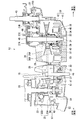
- FIG. 3 is a horizontal sectional view showing a power unit transmission device of FIG. 2.
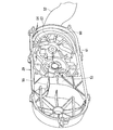
- FIG. 4 is a perspective view showing the case cover of FIGS. 2 and 3 as viewed from the inside.
- FIG. 4 is a schematic diagram illustrating a flow state of cooling air in the transmission device of FIG. 3.
- FIG. 6 is a partially enlarged schematic view showing a part (drive pulley side) of FIG. 5 in an enlarged manner.
- front and rear, left and right, and upper and lower expressions are based on the state shown in the figure or on the occupant when the vehicle is boarded.
- FIG. 1 is a side view of a scooter type motorcycle to which an embodiment of a cooling structure for a continuously variable transmission according to the present invention is applied.
- the scooter type motorcycle 1 includes an underbone type body frame 2.
- the vehicle body frame 2 is configured such that an under frame 4 extends downward from a head pipe 3 on the front head, and a seat rail 5 extends rearward and obliquely upward from a vehicle lower portion of the under frame 4.
- a front fork 6 is supported on the head pipe 3 together with the handle bar 7 so as to be rotatable left and right, and a front wheel 8 is pivotally supported at the front end of the front fork 6.
- a power unit 10 is pivotally supported at the lower center of the body frame 2 via a swing bracket 9 so as to be swingable in the vertical direction around the pivot shaft 11.
- the power unit 10 is generally used for a scooter as shown in FIGS. 1 and 2, and the engine 12 and the transmission device 13 are integrally formed, and the rear wheel 14 is directly supported on the rear portion of the transmission device 13. Is done.
- a rear cushion unit (not shown) is stretched between the rear portion of the transmission device 13 and the rear portion (seat rail 5) of the vehicle body frame 2, and the power unit 10 and the rear wheel 14 are buffered and suspended by the rear cushion unit.
- the engine 12 is configured such that a cylinder assembly 16 protrudes forward in a substantially horizontal direction from the vehicle front of a crankcase 15 as an engine case.
- the cylinder assembly 16 includes a cylinder block 17, a cylinder head 18, and a head cover 19 that are sequentially joined from the crankcase 15 side. Due to the combustion of the air-fuel mixture, the piston (not shown) reciprocates within the cylinder block 17, and the reciprocating motion causes the crankshaft 20 (FIG. 3) to rotate within the crankcase 15.
- a seating seat 21 is mounted on the body frame 2 above the seat rail 5 so as to be openable and closable, and an article storage box 22 capable of storing a helmet or the like is placed below the seating seat 21. Provided. For this reason, by opening the seating sheet 21, articles can be taken into and out of the article storage box 22.
- the vehicle body frame 2 is entirely covered with a synthetic resin frame cover 23 to improve the appearance and protect internal devices.
- Reference numeral 24 in FIG. 1 denotes an air cleaner.
- the scooter type motorcycle shown in FIG. 1 transmits the power of a drive pulley driven by an engine crankshaft via a belt to a driven pulley disposed so as to be rotatable relative to a driven shaft.
- the vehicle includes the transmission device 13 including the continuously variable transmission 25 capable of continuously changing the gear ratio.
- the transmission device 13 includes a continuously variable transmission 25 using a V-belt 37, a centrifugal clutch 26, and a transmission mechanism 27, shifting the driving force of the engine 12 to the rear wheel 14. introduce.
- a transmission case 28 as a case main body is integrally connected from one side (left side) of the crankcase 15 of the engine 12 and extends rearward of the vehicle.
- a case cover 29 covers an opening of the transmission case 28.
- the continuously variable transmission 25, the centrifugal clutch 26, and the transmission mechanism 27 are accommodated in a case space 30 as an accommodating space surrounded by the transmission case 28 and the case cover 29.
- the continuously variable transmission 25 is connected to the crankshaft 20 of the engine 12 so as to be integrally rotated, and is connected to a drive pulley 35 that is rotationally driven by the crankshaft 20 and a sleeve 32 that is rotatable relative to the driven shaft 31. And a V pulley 37 that is wound around the drive pulley 35 and the driven pulley 36 and transmits the rotational force (power) of the drive pulley 35 to the driven pulley 36.
- the drive pulley 35 is configured such that a fixed face 35A and a movable face 35B are opposed to each other
- the driven pulley 36 is also configured such that a fixed face 36A and a movable face 36B are opposed to each other.
- a V-belt 37 is disposed between the fixed face 35A and the movable face 35B of the drive pulley 35 and between the fixed face 36A and the movable face 36B of the driven pulley 36.
- a spring 34 is interposed between the movable face 36B of the driven pulley 36 and a base plate 39 (described later) of the centrifugal clutch 26, and the movable face 36B is constantly urged toward the fixed face 36A.
- the centrifugal force acting on the weight roller 33 changes according to the rotation speed of the engine 12 (that is, the rotation speed of the crankshaft 20). Move radially outward. As a result, the movable face 35B moves in the axial direction of the crankshaft 20 and approaches the fixed face 35A, and the belt winding radius of the drive pulley 35 increases. At this time, the driven pulley 36 moves away from the fixed face 36A by moving the movable face 36B on the sleeve 32 against the biasing force of the spring 34 in the axial direction of the sleeve 32 (that is, the axial direction of the driven shaft 31). The belt winding radius of the driven pulley 36 is reduced. In this way, the rotation of the crankshaft 20 is steplessly changed (for example, increased in speed), and the sleeve 32 is rotated.
- the centrifugal clutch 26 is disposed between the driven pulley 36 and the driven shaft 31, and transmits the rotational force of the driven pulley 36, that is, the rotational force (power) of the sleeve 32, to the driven shaft 31 when turned on, and transmits it when turned off. Is released (disconnected).
- the centrifugal clutch 26 is disposed on the driven shaft 31 adjacent to the movable face 36B of the driven pulley 36, and includes a clutch housing 38, a base plate 39, and a clutch shoe 40.
- the clutch housing 38 is formed by integrating a side wall 41 extending in the radial direction with a flange 42 extending in the axial direction, and the side wall 41 is rotatably attached to the driven shaft 31 and formed in a cup shape as a whole. Is done.
- the base plate 39 is fixed to the end of the sleeve 32, and the clutch shoe 40 is pivotally supported on the sleeve 32.
- the clutch shoe 40 is slidably provided on the inner surface of the flange portion 42 in the clutch housing 38.
- the rotational force transmitted to the driven pulley 36 and rotating the sleeve 32 rotates the base plate 39, and the clutch shoe 40 is brought into sliding contact with the inner surface of the flange portion 42 of the clutch housing 38 by the action of centrifugal force.
- the clutch housing 38 rotates integrally with the driven pulley 36, and the rotation of the driven pulley 36 is transmitted to the driven shaft 31.
- the rotational force transmitted to the driven shaft 31 is transmitted to the rear wheel 14 via the mission mechanism 27.
- the mission mechanism 27 decelerates the rotational force of the driven shaft 31 by the gear train (first mission gear 27A, second mission gear 27B, third mission gear 27C, fourth mission gear 27D) and transmits it to the output shaft 43.
- the first mission gear 27 ⁇ / b> A is formed at a position opposite to the centrifugal clutch 26 on the driven shaft 31.
- the second mission gear 27B is provided to rotate integrally with the intermediate shaft 44 and meshes with the first mission gear 27A.
- the third mission gear 27C is formed on the intermediate shaft 44.
- the fourth mission gear 27D is rotatably integrated with the output shaft 43 and meshes with the third mission gear 27C.
- the mission mechanism 27 is liquid-tightly isolated in a mission cover 45 provided in the transmission case 28 and immersed in oil.
- 3 denotes a kick starter shaft, and a kick starter mechanism 47 is operated by operating a kick starter lever (not shown) provided at the tip, and the crank shaft 20 is manually moved when the engine 12 is started. Rotate.
- a cooling fan (sirocco fan in the present embodiment) 51 is provided integrally on the case cover 29 side of the fixed face 35 ⁇ / b> A of the drive pulley 35.
- the case cover 29 is provided with an introduction duct 52 on the drive pulley 35 side (cooling fan 51 side) and a discharge duct at an intermediate position between the drive pulley 35 and the driven pulley 36. 53 is formed.
- the introduction duct 52 communicates with the case space 30 through an introduction opening 54 formed in the case cover 29.
- the discharge duct 53 communicates with the case space 30 through a discharge port 55 of the discharge duct 53, and communicates with the atmosphere through a discharge port 56 (FIG. 2) of the discharge duct 53.
- frictional heat is generated in the case space 30 of the transmission 13 due to the sliding contact between the V belt 37, the drive pulley 35, and the driven pulley 36 in the continuously variable transmission 25. Furthermore, frictional heat is also generated by sliding contact between the clutch housing 38 of the centrifugal clutch 26 and the clutch shoe 40.
- the outside air A from the introduction duct 52 is introduced as cooling air B into the case space 30 through the introduction opening 54 (FIG. 4).
- the cooling air B flows in the case space 30 from the drive pulley 35 side to the driven pulley 36 side as indicated by an arrow C by the pneumatic supply of the rotating cooling fan 51, and is exhausted from the discharge port 55 of the discharge duct 53. It becomes D and flows into the exhaust duct 53, and is exhausted from the exhaust port 56 (FIG. 2) of the exhaust duct 53 to the atmosphere. While the cooling air B flows in the case space 30, both the above-mentioned frictional heats are dissipated, and the continuously variable transmission 25 and the engine clutch 26 are cooled.
- the introduction groove 60 is formed along the outer peripheral edge 58 of the cooling fan 51 on the front end surface 57 corresponding to the cooling fan 51 inside the case cover 29.
- the introduction groove 60 is formed in a slope shape in which the groove depth gradually increases along the rotation direction P of the cooling fan 51. Further, the introduction groove 60 is formed so as to extend to a position where the deepest portion 61 is located behind the center of the cooling fan 51 (that is, the crankshaft 20) in the vehicle front-rear direction.
- the introduction groove 60 as described above is formed in the front end surface 57 inside the case cover 29, so that the space volume between the front end surface 57 of the case cover 29 and the outer peripheral edge 58 of the cooling fan 51 can be reduced.
- the case cover 29 gradually expands in the depth direction (vehicle width direction). For this reason, the cooling air B pumped by the rotating cooling fan 51 flows smoothly without staying in the introduction groove 60 and flows in the case space 30 from the drive pulley 35 side to the driven pulley 36 side at a high speed. As a result, the pumping efficiency of the cooling air B increases.
- a case space 30 in which a continuously variable transmission 25 including a drive pulley 35, a driven pulley 36, and a V-belt 37 is formed by a transmission case 28 and a case cover 29.
- the introduction groove 60 that guides the cooling air B to the inner front end surface 57 of the case cover 29 corresponding to the outer peripheral edge 58 of the cooling fan 51 provided on the case cover 29 side of the drive pulley 35 is cooled. It is formed so as to gradually become deeper along the rotation direction P of the fan 51.
- the cooling air B pumped by the cooling fan 51 flows in the introduction groove 60 and flows smoothly without stagnation, and the pumping efficiency of the cooling air B increases, and the continuously variable transmission 25.
- the cooling efficiency of the centrifugal clutch 26 can be improved.
- the case cover 29 Since the introduction groove 60 that guides the cooling air B is formed in the front end surface 57 corresponding to the cooling fan 51 inside the case cover 29 in the depth direction of the case cover 29, the case cover 29 and the cooling fan
- the case cover 29 does not expand in the radial direction of the cooling fan 51, compared to a case where a gap that extends in the radial direction of the cooling fan 51 is provided between the case cover 29 and the cooling fan 51.
- the case cover 29 can be downsized, the case cover 29 can be made highly rigid, and the cost of the power unit 10 can be reduced.
- the case cover 29 since the case cover 29 is downsized, the degree of freedom in layout of the oil filter 62 (FIG. 2), the oil strainer, and the like can be improved.
Landscapes
- Engineering & Computer Science (AREA)
- General Engineering & Computer Science (AREA)
- Mechanical Engineering (AREA)
- Chemical & Material Sciences (AREA)
- Combustion & Propulsion (AREA)
- Transportation (AREA)
- General Details Of Gearings (AREA)
- Transmissions By Endless Flexible Members (AREA)
Abstract
エンジンのクランク軸により駆動されるドライブプーリの動力を、従動軸に相対回転可能に配設されたドリブンプーリに、ベルトを介して伝達すると共に、変速比を連続的に変化させることが可能な無段変速機を備えた伝動装置を有する車両において、エンジンケースから延びる伝動ケースをケースカバーで覆うことにより、前記無段変速機を収容する収容空間を形成し、前記ドライブプーリの前記ケースカバー側に冷却ファンが設け、この冷却ファンの回転により、前記収容空間内へ冷却用空気を導入し流動させて前記無段変速機を冷却するために、前記ケースカバーの内側で前記冷却ファンに対応する箇所に、前記冷却用空気を導く溝を形成した。
Description
本発明は、無段変速機の冷却構造に係り、特に車両の伝動装置における無段変速機の冷却構造に関する。
一般に、車両、例えば、スクータ型自動二輪車では、エンジンと、無段変速機及び遠心クラッチ等を備えた伝動装置とが一体に構成され、無段変速機及び遠心クラッチ等は、エンジンケースから延びる伝動ケースと、この伝動ケースを覆うケースカバーとに囲まれて形成されるケース空間内に収容されている。
このような無段変速機は、エンジンのクランク軸により駆動されるドライブプーリの動力を、従動軸に相対回転可能に配設されたドリブンプーリに、ベルトを介し変速して伝達するものである。また、遠心クラッチは、無段変速機のドリブンプーリと従動軸の間で、動力の伝達と切り離しを選択的に行う。
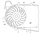
例えば、図7に示すように、前記ケース空間では、ドライブプーリ101に一体に設けられた冷却ファン102が回転することで、ケース空間100内に冷却用空気が導入されて流動し、この冷却用空気により無段変速機及び遠心クラッチが冷却される。
このような、従来の伝動装置では、伝動ケース103及びケースカバーと冷却ファン102との空間が狭い領域Xとなっているため、冷却ファン102から圧送された冷却用空気が領域Xに一旦滞留してしまい、その下流の領域Yで解放されて流速が局所的に高くなり、この結果、冷却用空気の圧送効率が低下していた。
そこで、このような問題点を解決するために、特許文献1及び2に記載の無段変速機の冷却構造が提案され、そこでは、伝動ケース及びケースカバーと冷却ファンとの空間を、冷却ファンの回転方向に沿って、冷却ファンの半径方向に徐々に拡大させることで、この空間の容積を漸次増大させ、これにより、冷却ファンにより圧送された冷却用空気の滞留を防止して、圧送効率を高めるものが開示されている。
これらの特許文献に記載の無段変速機の冷却構造では、冷却ファンによる冷却用空気の圧送効率が高められることで、ドライブプーリへ向かって流れる冷却用空気(例えば図7の領域Zの冷却用空気)の流速が上昇して、無段変速機等の冷却効率が向上する。
ところが、特許文献1及び2に記載の無段変速機の冷却構造では、伝動ケース及びケースカバーと冷却ファンとの空間を、冷却ファンの回転方向に沿って、冷却ファンの半径方向に徐々に拡大させることで、この空間の容積を漸次増大させているので、伝動ケースやケースカバーが大型化してしまう。このため、伝動装置の重量やコストが上昇するばかりか、オイルフィルタやオイルストレーナ等のレイアウトの自由度が制限されるなどの不具合が発生してしまう。
本発明の目的は、上述の事情を考慮してなされたものであり、冷却用空気を滞留させずスムーズに流動させることで無段変速機の冷却効率を向上できると共に、無段変速機を収容するケースカバーを小型化できる無段変速機の冷却構造を提供することにある。
上記目的を達成するために提供される本発明に係る無段変速機の冷却構造は、エンジンのクランク軸により駆動されるドライブプーリの動力を、従動軸に相対回転可能に配設されたドリブンプーリに、ベルトを介して伝達すると共に、変速比を連続的に変化させることが可能な無段変速機を備えた伝動装置を有する車両において、エンジンケースから延びる伝動ケースをケースカバーで覆うことにより、前記無段変速機を収容する収容空間が形成され、前記ドライブプーリの前記ケースカバー側に冷却ファンが設けられ、この冷却ファンの回転により、前記収容空間内へ冷却用空気を導入し流動させて前記無段変速機を冷却する、前記無段変速機の冷却構造であって、前記ケースカバーの内側で前記冷却ファンに対応する箇所に、前記冷却用空気を導く溝が形成されたことを特徴とする。
また、上記冷却構造において、前記溝は、冷却ファンの外周縁に沿ってケースカバーの内側に形成することが好ましい。
また、上記冷却構造において、前記溝は、冷却ファンの回転方向に沿い徐々に深くなるように、ケースカバーの内側に形成されることが好ましい。
また、上記冷却構造において前記溝は、最深部が冷却ファンの中心よりも車両前後方向の後方まで延びて形成されることが好ましい。
また、上記冷却構造において、前記溝は、冷却ファンの外周縁に沿ってケースカバーの内側に形成することが好ましい。
また、上記冷却構造において、前記溝は、冷却ファンの回転方向に沿い徐々に深くなるように、ケースカバーの内側に形成されることが好ましい。
また、上記冷却構造において前記溝は、最深部が冷却ファンの中心よりも車両前後方向の後方まで延びて形成されることが好ましい。
本発明によれば、ドライブプーリ、ドリブンプーリ及びベルトを備えてなる車両の無段変速機が、伝動ケーとケースカバーにて形成される収容空間内に収容され、ドライブプーリのケースカバー側に設けられた冷却ファンに対応する前記ケースカバーの内側に、冷却用空気を導く溝が形成されている。このため、冷却ファンにより圧送される冷却用空気は溝内を流動することで、滞留せずにスムーズに流れ、冷却用空気の圧送効率が上昇して、無段変速機の冷却効率を向上させることができる。
また、ケースカバーの内側で冷却ファンに対応する箇所に、冷却用空気を導く溝が形成される場合には、ケースカバーと冷却ファンとの間に冷却ファンの半径方向に拡がる隙間が設けられる場合に比べ、ケースカバーが冷却ファンの半径方向に拡大することがないので、ケースカバーを小型化できる。
尚、本発明の更なる特徴は、添付図面を参照して以下に記載される本発明にの実施例の説明により、さらに明確になる。
尚、本発明の更なる特徴は、添付図面を参照して以下に記載される本発明にの実施例の説明により、さらに明確になる。
以下、本発明を実施するための実施形態を添付図面に基づき説明する。尚、本実施形態の説明において、前後、左右、上下の表現は、図示の状態または、車両乗車時の乗員を基準にしたものである。
図1は本発明に係る無段変速機の冷却構造における一実施形態が適用されたスクータ型自動二輪車の側面図である。図1に示されるように、このスクータ型自動二輪車1は、アンダーボーン型の車体フレーム2を備える。この車体フレーム2は、前頭部のヘッドパイプ3からアンダーフレーム4が下方へ延出され、このアンダーフレーム4の車両下部からシートレール5が後斜め上方へ延出されて構成される。また、ヘッドパイプ3にフロントフォーク6が、ハンドルバー7と共に左右回動自在に支持され、このフロントフォーク6の先端に前輪8が軸支される。一方、車体フレーム2の下部中央には、スイングブラケット9を介してパワーユニット10が、ピボット軸11回りに上下方向に揺動可能に軸支される。
パワーユニット10は、図1及び図2に示すようにスクータ用として一般的に用いられるものであり、エンジン12と伝動装置13が一体に構成され、伝動装置13の後部に後輪14が直接軸支される。伝動装置13の後部と車体フレーム2の後部(シートレール5)との間に、図示しないリアクッションユニットが上下に掛け渡され、このリアクッションユニットによりパワーユニット10及び後輪14が緩衝懸架される。
エンジン12は、図2に示すように、エンジンケースとしてのクランクケース15の車両前方からシリンダアッセンブリ16が略水平方向に前傾して突設されて構成される。シリンダアッセンブリ16は、クランクケース15の側からシリンダブロック17、シリンダヘッド18及びヘッドカバー19が順次接合されてなる。混合気の燃焼によりシリンダブロック17内でピストン(不図示)が往復運動し、この往復運動によりクランクケース15内でクランク軸20(図3)が回転運動する。
また、図1に示すように、車体フレーム2におけるシートレール5の上方には着座シート21が開閉自在に載置され、この着座シート21の下方に、ヘルメット等を収納可能な物品収納ボックス22が設けられる。このため、着座シート21を開放することによって、物品収納ボックス22に物品の出し入れが可能になる。尚、車体フレーム2は合成樹脂製のフレームカバー23によって全体的に覆われ、外観の向上や内部機器の保護が図られている。図1中の符号24はエアクリーナを示す。
図1に示されるスクータ型自動二輪車は、後述のように、エンジンのクランク軸により駆動されるドライブプーリの動力を、従動軸に相対回転可能に配設されたドリブンプーリに、ベルトを介して伝達すると共に、変速比を連続的に変化させることが可能な無段変速機25を備えた伝動装置13を有する車両である。前記伝動装置13は、図3に示すように、Vベルト37を用いた無段変速機25と遠心クラッチ26とミッション機構27とを有し、エンジン12の駆動力を変速して後輪14へ伝達する。エンジン12のクランクケース15の一側部(左側部)から、ケース本体としての伝動ケース28が一体に連設されて車両後方へ延び、この伝動ケース28の開口をケースカバー29が覆う。これらの伝動ケース28とケースカバー29に囲まれた収容空間としてのケース空間30に、無段変速機25、遠心クラッチ26及びミッション機構27が収容される。
無段変速機25は、エンジン12のクランク軸20に回転一体に連結されて、このクランク軸20により回転駆動されるドライブプーリ35と、従動軸31に相対回転可能なスリーブ32に回転一体に連結されるドリブンプーリ36と、ドライブプーリ35とドリブンプーリ36に巻き掛けられて、ドライブプーリ35の回転力(動力)をドリブンプーリ36へ伝達するVベルト37とを有して構成される。
ドライブプーリ35は、固定フェイス35Aと可動フェイス35Bとが対向配置されて構成され、ドリブンプーリ36も、固定フェイス36Aと可動フェイス36Bとが対向配置されて構成される。ドライブプーリ35の固定フェイス35Aと可動フェイス35B間、ドリブンプーリ36の固定フェイス36Aと可動フェイス36B間にVベルト37が配置される。ドリブンプーリ36の可動フェイス36Bと遠心クラッチ26のベースプレート39(後述)との間にスプリング34が介装されて、可動フェイス36Bが固定フェイス36A側へ常時付勢される。
ドライブプーリ35では、エンジン12の回転数(つまりクランク軸20の回転数)に応じてウェイトローラ33に作用する遠心力が変化し、例えば遠心力の増大に応じてウェイトローラ33がドライブプーリ35の半径方向外方へ移動する。これにより、可動フェイス35Bがクランク軸20の軸方向に移動して固定フェイス35Aに接近し、ドライブプーリ35のベルト巻き掛け半径が拡大する。このとき、ドリブンプーリ36は、可動フェイス36Bがスプリング34の付勢力に抗してスリーブ32上を、このスリーブ32の軸方向(つまり従動軸31の軸方向)に移動して固定フェイス36Aから離れ、ドリブンプーリ36のベルト巻き掛け半径が縮小する。このようにして、クランク軸20の回転が無段階に変速(例えば増速)されてスリーブ32を回転させる。
遠心クラッチ26は、ドリブンプーリ36と従動軸31との間に配設され、ON時にはドリブンプーリ36の回転力、つまりスリーブ32の回転力(動力)を従動軸31へ伝達し、OFF時にはその伝達を解除(切り離し)する。この遠心クラッチ26は、従動軸31においてドリブンプーリ36の可動フェイス36Bに隣接して配置され、クラッチハウジング38、ベースプレート39及びクラッチシュー40を備えて構成される。
クラッチハウジング38は、半径方向に延びる側壁部41に、軸方向に延びるフランジ部42が一体化され、側壁部41が従動軸31に回転一体に取り付けられたものであり、全体としてカップ形状に形成される。ベースプレート39は、スリーブ32の端部に固着され、このスリーブ32にクラッチシュー40が枢支される。このクラッチシュー40は、クラッチハウジング38におけるフランジ部42の内面に摺接可能に設けられる。
従って、ドリブンプーリ36に伝達されスリーブ32を回転させた回転力はベースプレート39を回転させて、クラッチシュー40を遠心力の作用で、クラッチハウジング38のフランジ部42の内面に摺接させる。これにより、クラッチハウジング38がドリブンプーリ36と一体に回転し、ドリブンプーリ36の回転が従動軸31へ伝達される。この従動軸31に伝達された回転力は、ミッション機構27を経て後輪14へ伝達される。
ミッション機構27は、従動軸31の回転力をギア列(第1ミッションギア27A、第2ミッションギア27B、第3ミッションギア27C、第4ミッションギア27D)により減速して出力軸43へ伝達する。第1ミッションギア27Aは、従動軸31において遠心クラッチ26と反対位置に形成される。第2ミッションギア27Bは、中間軸44に回転一体に設けられて第1ミッションギア27Aに噛み合う。第3ミッションギア27Cは中間軸44に形成される。第4ミッションギア27Dは、出力軸43に回転一体に設けられて第3ミッションギア27Cに噛み合う。このミッション機構27により、従動軸31の回転力が所望の減速比に減速されて出力軸43へ伝達され、この出力軸43に回転一体に結合された後輪14を駆動する。
尚、ミッション機構27は、伝動ケース28に設けられたミッションカバー45内で液密に隔離され、オイルに浸されている。また、図3中の符号46はキックスタータ軸であり、先端に設けられたキックスタータレバー(不図示)の操作によりキックスタータ機構47が作動されて、エンジン12の始動時にクランク軸20を人力で回転させる。
ところで、図3及び図5に示すように、ドライブプーリ35の固定フェイス35Aにおけるケースカバー29側に、冷却ファン(本実施形態ではシロッコファン)51が回転一体に設けられる。また、図3及び図4に示すように、ケースカバー29は、ドライブプーリ35側(冷却ファン51側)に導入ダクト52が設けられると共に、ドライブプーリ35とドリブンプーリ36との中間位置に排出ダクト53が形成される。導入ダクト52は、ケースカバー29に形成された導入開口54によりケース空間30に連通する。また、排出ダクト53は、この排出ダクト53の排出口55によりケース空間30に連通し、排出ダクト53の排風口56(図2)により大気に連通する。
ここで、エンジンが始動すると、伝動装置13のケース空間30内では、無段変速機25におけるVベルト37とドライブプーリ35及びドリブンプーリ36との摺接により摩擦熱が発生する。更に、遠心クラッチ26のクラッチハウジング38とクラッチシュー40との摺接によっても摩擦熱が発生する。
図5に示すように、この時、冷却ファン51の回転により、導入ダクト52からの外気Aが導入開口54(図4)を経てケース空間30内へ冷却用空気Bとして導入される。この冷却用空気Bは、回転する冷却ファン51の空気圧送により、ケース空間30内をドライブプーリ35側からドリブンプーリ36側へ矢印Cに示すように流動し、排出ダクト53の排出口55から排気Dとなって排出ダクト53内へ流れ、この排出ダクト53の排風口56(図2)から大気へ排出される。冷却用空気Bがケース空間30内を流動する間に上述の両摩擦熱が放散されて、無段変速機25及びエンジンクラッチ26は冷却される。
本実施形態では、図3、図4及び図6に示すように、ケースカバー29の内側で冷却ファン51に対応する前端面57に、冷却ファン51の外周縁58に沿って導入溝60が形成されている。この導入溝60は、冷却ファン51の回転方向Pに沿って溝深さが徐々に深くなるスロープ形状に形成される。更に、この導入溝60は、最深部61が冷却ファン51の中心(即ちクランク軸20)よりも車両前後方向の後方になる位置まで延在して形成される。
前記ケースカバー29の内側の前端面57に上述のような導入溝60が形成されることで、ケースカバー29の前端面57と冷却ファン51の外周縁58との間の空間容積は、冷却ファン51の回転方向Pに沿って、ケースカバー29の奥行き方向(車幅方向)に徐々に拡大する。このため、回転する冷却ファン51により圧送された冷却用空気Bは、導入溝60内を滞留することなくスムーズに流れて、ケース空間30内を高速でドライブプーリ35側からドリブンプーリ36側へ流動し、冷却用空気Bの圧送効率が上昇する。
以上のように構成されたことから、本実施形態によれば、次の効果(1)および(2)を奏する。
(1)図5及び図6に示すように、ドライブプーリ35、ドリブンプーリ36及びVベルト37を備えてなる無段変速機25が、伝動ケース28とケースカバー29にて形成されるケース空間30内に収容され、ドライブプーリ35のケースカバー29側に設けられた冷却ファン51の外周縁58に対応するケースカバー29の内側の前端面57に、冷却用空気Bを導く導入溝60が、冷却ファン51の回転方向Pに沿って徐々に深くなるように形成されている。このため、冷却ファン51により圧送される冷却用空気Bは導入溝60内を流動することで、滞留せずにスムーズに流れ、冷却用空気Bの圧送効率が上昇して、無段変速機25及び遠心クラッチ26の冷却効率を向上させることができる。
(1)図5及び図6に示すように、ドライブプーリ35、ドリブンプーリ36及びVベルト37を備えてなる無段変速機25が、伝動ケース28とケースカバー29にて形成されるケース空間30内に収容され、ドライブプーリ35のケースカバー29側に設けられた冷却ファン51の外周縁58に対応するケースカバー29の内側の前端面57に、冷却用空気Bを導く導入溝60が、冷却ファン51の回転方向Pに沿って徐々に深くなるように形成されている。このため、冷却ファン51により圧送される冷却用空気Bは導入溝60内を流動することで、滞留せずにスムーズに流れ、冷却用空気Bの圧送効率が上昇して、無段変速機25及び遠心クラッチ26の冷却効率を向上させることができる。
(2)ケースカバー29の内側で冷却ファン51に対応する前端面57に、冷却用空気Bを導く導入溝60が、ケースカバー29の奥行き方向に形成されているので、ケースカバー29と冷却ファン51との間に冷却ファン51の半径方向に広がる隙間が設けられる場合に比べ、ケースカバー29が冷却ファン51の半径方向に拡大することがない。この結果、ケースカバー29を小型化できると共に、そのケースカバー29の高剛性化を実現でき、更に、パワーユニット10のコストを低減できる。また、ケースカバー29が小型化されることで、オイルフィルタ62(図2)やオイルストレーナ等のレイアウトの自由度を向上させることができる。
以上、本発明の実施形態を、スクータ型自動二輪車等の車両を例に、説明したが、この実施形態は、例として提示したものであり、発明の範囲を限定することは意図していない。この実施形態は、その他の様々な形態で実施されることが可能であり、発明の要旨を逸脱しない範囲で、種々の省略、置き換え、変更を行うことができる。
12 エンジン
15 クランクケース(エンジンケース)
20 クランク軸
25 無段変速機
28 伝動ケース
29 ケースカバー
30 ケース空間(収容空間)
31 従動軸
35 ドライブプーリ
36 ドリブンプーリ
37 Vベルト
51 冷却ファン
57 前端面
58 外周縁
60 導入溝
61 最深部
B 冷却用空気
P 回転方向
15 クランクケース(エンジンケース)
20 クランク軸
25 無段変速機
28 伝動ケース
29 ケースカバー
30 ケース空間(収容空間)
31 従動軸
35 ドライブプーリ
36 ドリブンプーリ
37 Vベルト
51 冷却ファン
57 前端面
58 外周縁
60 導入溝
61 最深部
B 冷却用空気
P 回転方向
Claims (4)
- エンジンのクランク軸により駆動されるドライブプーリの動力を、従動軸に相対回転可能に配設されたドリブンプーリに、ベルトを介して伝達すると共に、変速比を連続的に変化させることが可能な無段変速機を備えた伝動装置を有する車両において、エンジンケースから延びる伝動ケースをケースカバーで覆うことにより、前記無段変速機を収容する収容空間が形成され、前記ドライブプーリの前記ケースカバー側に冷却ファンが設けられ、この冷却ファンの回転により、前記収容空間内へ冷却用空気を導入し流動させて前記無段変速機を冷却する、前記無段変速機の冷却構造であって、
前記ケースカバーの内側で前記冷却ファンに対応する箇所に、前記冷却用空気を導く溝が形成されたことを特徴とする無段変速機の冷却構造。 - 前記溝は、冷却ファンの外周縁に沿ってケースカバーの内側に形成されたことを特徴とする請求項1に記載の無段変速機の冷却構造。
- 前記溝は、冷却ファンの回転方向に沿い徐々に深くなるように、ケースカバーの内側に形成されたことを特徴とする請求項1または2に記載の無段変速機の冷却構造。
- 前記溝は、最深部が冷却ファンの中心よりも車両前後方向の後方まで延びて形成されたことを特徴とする請求項3に記載の無段変速機の冷却構造。
Priority Applications (1)
| Application Number | Priority Date | Filing Date | Title |
|---|---|---|---|
| CN201580001813.5A CN107076292B (zh) | 2014-07-22 | 2015-06-12 | 无级变速器的冷却结构 |
Applications Claiming Priority (2)
| Application Number | Priority Date | Filing Date | Title |
|---|---|---|---|
| JP2014148932A JP6331815B2 (ja) | 2014-07-22 | 2014-07-22 | 無段変速機の冷却構造 |
| JP2014-148932 | 2014-07-22 |
Publications (1)
| Publication Number | Publication Date |
|---|---|
| WO2016013326A1 true WO2016013326A1 (ja) | 2016-01-28 |
Family
ID=55162862
Family Applications (1)
| Application Number | Title | Priority Date | Filing Date |
|---|---|---|---|
| PCT/JP2015/066985 Ceased WO2016013326A1 (ja) | 2014-07-22 | 2015-06-12 | 無段変速機の冷却構造 |
Country Status (3)
| Country | Link |
|---|---|
| JP (1) | JP6331815B2 (ja) |
| CN (1) | CN107076292B (ja) |
| WO (1) | WO2016013326A1 (ja) |
Families Citing this family (2)
| Publication number | Priority date | Publication date | Assignee | Title |
|---|---|---|---|---|
| CN115285275B (zh) * | 2022-08-02 | 2023-04-28 | 浙江钱江摩托股份有限公司 | 摩托车变速器的冷却结构 |
| CN119933839B (zh) * | 2025-02-18 | 2025-09-23 | 重庆银钢科技(集团)有限公司 | 一种发动机风道 |
Citations (4)
| Publication number | Priority date | Publication date | Assignee | Title |
|---|---|---|---|---|
| JP2004204988A (ja) * | 2002-12-26 | 2004-07-22 | Yamaha Motor Co Ltd | Vベルト式無段変速機の冷却構造 |
| JP2009513862A (ja) * | 2005-10-28 | 2009-04-02 | レスメド・リミテッド | 単段式ブロワ又は多段式ブロワ及び入れ子式渦形室及び/又は該渦形室のための羽根車 |
| JP3168137U (ja) * | 2011-03-15 | 2011-06-02 | スズキ株式会社 | 変速装置の冷却構造 |
| JP2014058884A (ja) * | 2012-09-17 | 2014-04-03 | Otics Corp | ターボチャージャ |
Family Cites Families (8)
| Publication number | Priority date | Publication date | Assignee | Title |
|---|---|---|---|---|
| JP4293796B2 (ja) * | 2003-01-31 | 2009-07-08 | ヤマハ発動機株式会社 | Vベルト式無段変速機の冷却構造 |
| JP4700260B2 (ja) * | 2003-04-18 | 2011-06-15 | 富士重工業株式会社 | 無段変速機 |
| JP4553298B2 (ja) * | 2004-08-05 | 2010-09-29 | 本田技研工業株式会社 | 電動車両のモータ冷却構造 |
| JP4801814B2 (ja) * | 2006-09-26 | 2011-10-26 | 本田技研工業株式会社 | 車両用無段変速機の冷却構造 |
| JP2010236626A (ja) * | 2009-03-31 | 2010-10-21 | Fuji Heavy Ind Ltd | Vベルト式無段変速機の冷却装置 |
| CN102483146B (zh) * | 2009-09-03 | 2015-07-15 | 本田技研工业株式会社 | V带式无极变速器的冷却风导入构造 |
| JP5352575B2 (ja) * | 2010-12-28 | 2013-11-27 | 本田技研工業株式会社 | Vベルト式無段変速機の冷却風取り入れ構造 |
| US8834307B2 (en) * | 2011-10-06 | 2014-09-16 | Kawasaki Jukogyo Kabushiki Kaisha | Belt type continuously variable transmission |
-
2014
- 2014-07-22 JP JP2014148932A patent/JP6331815B2/ja active Active
-
2015
- 2015-06-12 CN CN201580001813.5A patent/CN107076292B/zh not_active Expired - Fee Related
- 2015-06-12 WO PCT/JP2015/066985 patent/WO2016013326A1/ja not_active Ceased
Patent Citations (4)
| Publication number | Priority date | Publication date | Assignee | Title |
|---|---|---|---|---|
| JP2004204988A (ja) * | 2002-12-26 | 2004-07-22 | Yamaha Motor Co Ltd | Vベルト式無段変速機の冷却構造 |
| JP2009513862A (ja) * | 2005-10-28 | 2009-04-02 | レスメド・リミテッド | 単段式ブロワ又は多段式ブロワ及び入れ子式渦形室及び/又は該渦形室のための羽根車 |
| JP3168137U (ja) * | 2011-03-15 | 2011-06-02 | スズキ株式会社 | 変速装置の冷却構造 |
| JP2014058884A (ja) * | 2012-09-17 | 2014-04-03 | Otics Corp | ターボチャージャ |
Also Published As
| Publication number | Publication date |
|---|---|
| CN107076292B (zh) | 2019-06-18 |
| JP2016023729A (ja) | 2016-02-08 |
| JP6331815B2 (ja) | 2018-05-30 |
| CN107076292A (zh) | 2017-08-18 |
Similar Documents
| Publication | Publication Date | Title |
|---|---|---|
| CN1738160B (zh) | 电动车辆的电动机冷却结构 | |
| JP4531481B2 (ja) | パワーユニットの冷却装置 | |
| JP5301183B2 (ja) | パワーユニット | |
| JP5030603B2 (ja) | 樹脂ブロックベルトを有するベルト式無段変速機を備えた自動二輪車 | |
| JP5648578B2 (ja) | 多板式自動遠心クラッチ装置 | |
| JP2007038736A (ja) | 鞍乗型車両 | |
| JP5145095B2 (ja) | パワーユニット | |
| JP5486872B2 (ja) | パワーユニットの冷却装置 | |
| US7487853B2 (en) | Saddle-type vehicle | |
| JP2007062715A (ja) | 鞍乗型車両 | |
| JP6331815B2 (ja) | 無段変速機の冷却構造 | |
| JP2011027176A (ja) | 自動二輪車のパワーユニット | |
| CN101713313B (zh) | 发动机的油面计配置结构 | |
| CN110206656A (zh) | 动力单元 | |
| JP3150482U (ja) | 鞍乗型車両 | |
| JP3168137U (ja) | 変速装置の冷却構造 | |
| JP2017198321A (ja) | 無段階変速装置 | |
| JP3150483U (ja) | 自動二輪車 | |
| JP5138528B2 (ja) | エンジンの冷却構造 | |
| JP5301184B2 (ja) | パワーユニット | |
| JP5521903B2 (ja) | ベルト式自動変速機の冷却構造 | |
| JP2008185055A (ja) | 自動二輪車 | |
| JP2010236520A (ja) | キック式始動装置付き内燃機関 | |
| JP6893524B2 (ja) | 無段変速装置 | |
| JP2017196947A (ja) | 鞍乗型車両 |
Legal Events
| Date | Code | Title | Description |
|---|---|---|---|
| 121 | Ep: the epo has been informed by wipo that ep was designated in this application |
Ref document number: 15824923 Country of ref document: EP Kind code of ref document: A1 |
|
| NENP | Non-entry into the national phase |
Ref country code: DE |
|
| 122 | Ep: pct application non-entry in european phase |
Ref document number: 15824923 Country of ref document: EP Kind code of ref document: A1 |