WO2016013165A1 - 防水接着体及び防水接着体の製造方法 - Google Patents
防水接着体及び防水接着体の製造方法 Download PDFInfo
- Publication number
- WO2016013165A1 WO2016013165A1 PCT/JP2015/003410 JP2015003410W WO2016013165A1 WO 2016013165 A1 WO2016013165 A1 WO 2016013165A1 JP 2015003410 W JP2015003410 W JP 2015003410W WO 2016013165 A1 WO2016013165 A1 WO 2016013165A1
- Authority
- WO
- WIPO (PCT)
- Prior art keywords
- adherend
- rubber
- layer
- elastic
- elastic body
- Prior art date
- Legal status (The legal status is an assumption and is not a legal conclusion. Google has not performed a legal analysis and makes no representation as to the accuracy of the status listed.)
- Ceased
Links
Images



Classifications
-
- B—PERFORMING OPERATIONS; TRANSPORTING
- B32—LAYERED PRODUCTS
- B32B—LAYERED PRODUCTS, i.e. PRODUCTS BUILT-UP OF STRATA OF FLAT OR NON-FLAT, e.g. CELLULAR OR HONEYCOMB, FORM
- B32B7/00—Layered products characterised by the relation between layers; Layered products characterised by the relative orientation of features between layers, or by the relative values of a measurable parameter between layers, i.e. products comprising layers having different physical, chemical or physicochemical properties; Layered products characterised by the interconnection of layers
- B32B7/04—Interconnection of layers
- B32B7/12—Interconnection of layers using interposed adhesives or interposed materials with bonding properties
-
- B—PERFORMING OPERATIONS; TRANSPORTING
- B32—LAYERED PRODUCTS
- B32B—LAYERED PRODUCTS, i.e. PRODUCTS BUILT-UP OF STRATA OF FLAT OR NON-FLAT, e.g. CELLULAR OR HONEYCOMB, FORM
- B32B25/00—Layered products comprising a layer of natural or synthetic rubber
- B32B25/04—Layered products comprising a layer of natural or synthetic rubber comprising rubber as the main or only constituent of a layer, which is next to another layer of the same or of a different material
-
- C—CHEMISTRY; METALLURGY
- C09—DYES; PAINTS; POLISHES; NATURAL RESINS; ADHESIVES; COMPOSITIONS NOT OTHERWISE PROVIDED FOR; APPLICATIONS OF MATERIALS NOT OTHERWISE PROVIDED FOR
- C09J—ADHESIVES; NON-MECHANICAL ASPECTS OF ADHESIVE PROCESSES IN GENERAL; ADHESIVE PROCESSES NOT PROVIDED FOR ELSEWHERE; USE OF MATERIALS AS ADHESIVES
- C09J11/00—Features of adhesives not provided for in group C09J9/00, e.g. additives
- C09J11/02—Non-macromolecular additives
- C09J11/06—Non-macromolecular additives organic
-
- C—CHEMISTRY; METALLURGY
- C09—DYES; PAINTS; POLISHES; NATURAL RESINS; ADHESIVES; COMPOSITIONS NOT OTHERWISE PROVIDED FOR; APPLICATIONS OF MATERIALS NOT OTHERWISE PROVIDED FOR
- C09J—ADHESIVES; NON-MECHANICAL ASPECTS OF ADHESIVE PROCESSES IN GENERAL; ADHESIVE PROCESSES NOT PROVIDED FOR ELSEWHERE; USE OF MATERIALS AS ADHESIVES
- C09J121/00—Adhesives based on unspecified rubbers
-
- C—CHEMISTRY; METALLURGY
- C09—DYES; PAINTS; POLISHES; NATURAL RESINS; ADHESIVES; COMPOSITIONS NOT OTHERWISE PROVIDED FOR; APPLICATIONS OF MATERIALS NOT OTHERWISE PROVIDED FOR
- C09J—ADHESIVES; NON-MECHANICAL ASPECTS OF ADHESIVE PROCESSES IN GENERAL; ADHESIVE PROCESSES NOT PROVIDED FOR ELSEWHERE; USE OF MATERIALS AS ADHESIVES
- C09J5/00—Adhesive processes in general; Adhesive processes not provided for elsewhere, e.g. relating to primers
- C09J5/04—Adhesive processes in general; Adhesive processes not provided for elsewhere, e.g. relating to primers involving separate application of adhesive ingredients to the different surfaces to be joined
Definitions
- the present invention relates to a waterproof adhesive body in which a plurality of adherends are bonded and a method for manufacturing the waterproof adhesive body.
- waterproofing has been ensured in the housings of electronic devices such as smartphones and mobile phones.
- a method for ensuring the waterproofness of the housing for example, a plurality of components constituting the housing are bonded with an adhesive, or the housing is configured through an integrally formed elastic member or a separately prepared elastic member.
- a method of fitting together components see Patent Document 1 and Patent Document 2
- a method of bonding a plurality of components with a waterproof adhesive for example, a double-sided tape with a urethane foam base
- Patent Document 4 discloses a method for ensuring waterproofness of a casing having a stepped adhesive surface.
- one side of a workpiece with a hydrophobic surface is coated with a primer, and the surface coated with the primer is laminated by irradiating ultraviolet rays onto the silicone component.
- a technique for heating and bonding is known (for example, see Patent Document 5).
- the waterproof adhesive is a double-faced tape made of a urethane foam base
- the voids in the foam urethane base communicate with both ends of the waterproof adhesive. Therefore, there is a possibility that a problem that waterproofness cannot be secured may occur.
- the foaming rate when generating the foamed urethane base material it is difficult to secure the waterproofness unless the width of the waterproof adhesive material is currently larger than at least 1.0 mm.
- the waterproof adhesive cannot properly follow the bonding surface, and there is a possibility that waterproofness cannot be ensured.
- the present invention has been made in view of the above problems, and an object of the present invention is to provide a technique capable of appropriately bonding a plurality of adherends while ensuring waterproofness on a narrow adhesive surface. It is.
- a waterproof adhesive body is a waterproof adhesive body in which a first adherend and a second adherend are bonded to each other.
- a rubber-like elastic layer, a coat layer containing a silane compound, or a rubber-like elastic layer added with a silane compound is formed on the adhesion surface or the adhesion surface of the second adherend, and the first adherend and The adhesion surface of the second adherend has a narrow surface portion with a width of 1.0 mm or less, and the first adherend and the second adherend are waterproofed by being integrally bonded on the adhesion surface. Is secured.
- a rubber-like elastic body layer is further formed on the adhesive surface of the first adherend, and a rubber-like elasticity is provided on the adhesive surface of the second adherend.
- a body layer or a coat layer containing a silane compound is formed, or a rubber-like elastic body layer to which a silane compound is added is formed on at least one adhesive surface of the first adherend or the second adherend. ing.
- the first adherend further includes a first adherend substrate portion on which a rubber-like elastic layer is formed, and the first adherend is rubbery.
- the width of the elastic body layer and the width of the surface on which the rubber-like elastic body layer of the first adherend substrate portion is formed are the same.
- the second adherend has a second adherend substrate portion on which a rubber-like elastic layer or a coat layer is formed, and the second adherend
- the width of the rubber-like elastic body layer or coat layer is the same as the width of the surface of the second adherend substrate portion on which the rubber-like elastic body layer or coat layer is formed.
- the first adherend is bonded to the opposite side of the first adherend to the second adherend, and the third adherend is bonded.
- the adhesion surface of the body with the first adherend is formed of a rubber-like elastic layer or a coat layer containing a silane compound, and the adhesion surface between the first adherend and the third adherend has a width of 1
- the first adherend and the third adherend are integrally joined together on the adhesive surface to ensure waterproofness.
- the adhesive surface of the first adherend is formed into a convex curved surface
- the adhesive surface of the second adherend is formed into a concave curved surface corresponding to the convex curved surface.
- the adhesive surface between the first adherend and the second adherend is in the longitudinal direction, and the adhesion direction between the first adherend and the second adherend. Have a step.
- the adhesive surface of the first adherend is formed of a rubber-like elastic layer and a coat layer containing a silane compound
- the adhesive surface of the second adherend is The rubber-like elastic body layer and the coat layer containing the silane compound are integrally bonded to the rubber-like elastic body layer of the first adherend and the coat layer containing the silane compound of the second adherend.
- the coat layer containing the silane compound of the second adherend and the rubber-like elastic layer of the first adherend are integrally joined.
- the rubber-like elastic body layer further includes silicone rubber.
- a waterproof adhesive body is a waterproof adhesive body in which a first adherend and a second adherend are bonded to each other, and is an adhesive surface of the first adherend or a second adherend.
- a rubber-like elastic body layer, a coat layer containing a silane compound, or a rubber-like elastic body layer to which a silane compound is added is formed on the adhesion surface of the first and second adherends.
- the surface has a step with respect to the bonding direction of the first adherend and the second adherend in the longitudinal direction, and the first adherend and the second adherend are integrally bonded on the adhesion surface. As a result, waterproofness is ensured.
- a rubber-like elastic body layer is further formed on an adhesive surface of the first adherend with the second adherend, and the first adherend of the second adherend is formed.
- a rubber-like elastic body layer or a coat layer containing a silane compound is formed on the adhesion surface with the adherend.
- a waterproof adhesive body manufacturing method is a waterproof adhesive body manufacturing method for manufacturing a waterproof adhesive body in which a first adherend and a second adherend are bonded.
- the bonding surface to which the body and the second adherend are bonded has a narrow surface portion with a width in the short direction of 1.0 mm or less, and the bonding surface of the first adherend or the second adherend is A layer forming step of forming a rubber-like elastic body layer, a coat layer containing a silane compound or a rubber-like elastic body layer containing a silane compound on the adhesive surface; and an adhesive surface of the first adherend or a second adherend A surface modification treatment is performed on the adhesive surface, and the first adherend and the second adherend are integrally joined at the adhesive surface to ensure waterproofness.
- a rubber-like elastic body layer is formed on the adhesive surface of the first adherend, and the adhesive surface of the second adherend is It is a step of forming a rubber-like elastic body layer or a coat layer containing a silane compound, or forming a rubber-like elastic body layer containing a silane compound on one of the first adherend and the second adherend.
- a plurality of adherends can be appropriately bonded while ensuring waterproofness on a narrow bonding surface.
- FIG. 1 is an exploded perspective view of an electronic device casing according to the first embodiment of the present invention.
- FIG. 2 is a partial cross-sectional view and a partial front view of the electronic device casing according to the first embodiment of the present invention.
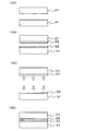
- FIG. 3 is a diagram for explaining a manufacturing process in the method for manufacturing the electronic device casing according to the first embodiment of the present invention.
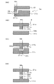
- FIG. 4 is a partial cross-sectional view of the electronic device casing according to the second to fifth embodiments of the present invention.
- FIG. 5 is a partial configuration diagram of a waterproof adhesive body according to sixth to seventeenth embodiments of the present invention.
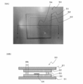
- FIG. 6 is a photograph and a cross-sectional view of an evaluation sample for evaluating the embodiment of the present invention.
- FIG. 7 is a diagram showing the evaluation test results of the waterproof effect in the evaluation sample for evaluating the embodiment of the present invention.
- FIG. 1 is an exploded perspective view of an electronic device casing according to the first embodiment of the present invention.
- FIG. 2 is a partial cross-sectional view and a partial front view of the electronic device casing according to the first embodiment of the present invention.
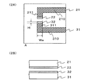
- (2A) is a cross-sectional view enlarging the range A in FIG. 1
- (2B) is a partial front view from the arrow B in FIG.
- the electronic device casing 1 has an upper casing 2 (an example of a first adherend) and a lower casing 3 (an example of a second adherend).
- the upper housing 2 includes an upper housing base material 21 and a rubber-like elastic body layer 22.
- the upper housing substrate 21 includes a bottom surface portion 210 and a wall portion 211 formed by rising from the outer edge of the bottom surface portion 210.
- the upper housing base 21 is made of, for example, a metal such as aluminum or magnesium alloy, or a reinforced resin such as carbon fiber (CF) or glass fiber (GF), such as glass fiber reinforced polycarbonate, resin film, resin sheet, or ceramic. It is composed of glass or the like.
- the width Wa in the short direction of the side surface of the lower casing of the wall 211 is, for example, 1.0 mm or less.
- the width Wa is preferably 0.05 to 1.0 mm, more preferably 0.08 to 0.8 mm. Thereafter, the same applies to a width of 1.0 mm or less.
- the rubber-like elastic body layer 22 is formed in an annular shape on the side surface of the lower housing of the wall portion 211.
- the width of the rubber-like elastic layer 22 in the short direction is the same as the width of the side surface of the lower housing of the wall 211. Therefore, the side surface of the wall part 211 and the side surface of the rubber-like elastic body layer 22 are flush with each other.
- the entire surface of the rubber-like elastic body layer 22 on the lower housing side is an adhesive surface that adheres to a rubber-like elastic body layer 32 described later, and corresponds to a narrow surface portion.
- the thickness H of the rubber-like elastic layer 22 is, for example, 150 ⁇ m or less, and preferably 100 ⁇ m or less.
- the rubber-like elastic body constituting the rubber-like elastic body layer 22 is a thermosetting elastomer such as urethane rubber, isoprene rubber, ethylene propylene rubber, natural rubber, ethylene propylene diene rubber, styrene butadiene rubber, or silicone rubber; urethane, ester It is preferably composed of thermoplastic elastomers such as styrene, olefin, butadiene, or fluorine; or composites thereof, and particularly preferably composed of silicone rubber. Further, the rubber-like elastic body constituting the rubber-like elastic body layer 22 may be primary vulcanized or secondary vulcanized. The rubber-like elastic body may be colored.
- Examples of the rubber-like elastic layer 22 include X-34-1802A / B manufactured by Shin-Etsu Chemical Co., Ltd. (durometer type A hardness (hereinafter referred to as rubber hardness A) 15 to 35) according to the measurement method of JISK6253, Shin-Etsu. Silicone rubber produced using X-32-2170A / B (rubber hardness A 10 or more and 25 or less), KE-1935A / B (rubber hardness A 55), etc., manufactured by Chemical Industry Co., Ltd. can be used.
- the rubber hardness A of the rubber-like elastic layer 5 is preferably 10 or more and 80 or less.
- the lower housing 3 has a lower housing base 31 and a rubber-like elastic body layer 32.
- the lower housing base 31 includes a bottom surface portion 310 and a wall portion 311 formed to rise from the outer edge of the bottom surface portion 310.
- the lower housing base 31 is made of, for example, a metal such as aluminum or magnesium alloy, or a reinforced resin such as carbon fiber (CF) or glass fiber (GF), such as glass fiber reinforced polycarbonate, resin film, resin sheet, or ceramic. It is composed of glass or the like.
- the width Wa in the lateral direction of the side surface of the upper housing of the wall 311 is, for example, 1.0 mm or less.
- the side surface of the upper housing of the wall portion 311 corresponds to a narrow surface portion.
- the rubber-like elastic body layer 32 is formed in an annular shape on the side surface of the upper housing of the wall portion 311.
- the width of the rubber-like elastic layer 32 in the short direction is the same as the width of the side surface of the upper housing of the wall 311. Therefore, the side surface of the wall portion 311 and the side surface of the rubber-like elastic layer 23 are flush with each other.
- the entire surface of the rubber-like elastic body layer 32 on the upper housing side is an adhesive surface that adheres to the rubber-like elastic body layer 22 and corresponds to a narrow surface portion.
- the thickness H of the rubber-like elastic layer 32 is, for example, 150 ⁇ m or less, and preferably 100 ⁇ m or less. This thickness is thinner than the thickness of the existing waterproof adhesive material.
- the rubber-like elastic body layer 32 is made of the same or the same kind of rubber-like elastic body as the rubber-like elastic body layer 22 described above.
- the rubber-like elastic body layer 22 of the upper housing 2 and the rubber-like elastic body layer 32 of the lower housing 3 are integrally joined as will be described later. .
- the total thickness of the rubber-like elastic body layer 22 of the upper housing 2 and the rubber-like elastic body layer 32 of the lower housing 3 can be, for example, 10 ⁇ m or more and 100 ⁇ m or less. Can also be thinned.
- a coating layer containing a silane compound may be used instead of one of the rubber-like elastic body layer 22 and the rubber-like elastic body layer 32.
- the coating layer containing a silane compound include a silane coupling agent layer and a siloxane-based coating layer.
- the silane coupling agent may be of any type as long as it is suitable for the upper housing substrate 21.
- the silane coupling agent layer may be composed of KBE-903 manufactured by Shin-Etsu Chemical Co., Ltd., or one or two types of silane coupling agents diluted with a solvent to form a primer. Alternatively, KPB-40) manufactured by Shin-Etsu Chemical Co., Ltd. may be used.
- the siloxane-based coating layer there is a coating layer in which linear dimethylpolysiloxane is cured and fixed on the substrate surface by an arbitrary method.
- the curing method of the coating agent for the coating layer may be a condensation reaction or addition reaction type utilizing heat, or an ultraviolet ray or electron beam.
- the form of the coating agent may be any of a solvent type, an emulsion type, and a solventless type.
- the coating agent is a type in which both ends, or linear methyl vinyl polysiloxane having vinyl groups at both ends and chains, and methyl hydrogen polysiloxane are reacted in the presence of a platinum catalyst.
- There is an addition reaction type silicone agent for peeling, and KS-774 manufactured by Shin-Etsu Chemical Co., Ltd. can be used.
- the siloxane-based coating layer has a siloxane bond as a skeleton and an organic group bonded to a silicon atom, and is classified from monofunctional to tetrafunctional, especially trifunctional or tetrafunctional.
- Organopolysiloxane may be used, and for example, colloidal silica may be used as a tetrafunctional component.
- a bifunctional monomer may be introduced as necessary to impart flexibility, or a silane coupling agent may be introduced to improve adhesion, for example, a siloxane hard
- KP-85 manufactured by Shin-Etsu Chemical Co., Ltd. may be used.
- the material for the siloxane-based coating layer may be a hydrophilic coating agent containing crystalline or non-crystalline silica, for example, a mixture of amorphous silica, methanol, isopropyl alcohol, or the like.
- a hydrophilic coating agent for example, Excel Pure manufactured by Chuo Automobile Co., Ltd. may be used.
- FIG. 3 is a diagram for explaining a manufacturing process in the method for manufacturing the electronic device casing according to the first embodiment of the present invention.
- an upper housing base material 21 and a lower housing base material 31 are prepared.
- a rubber-like elastic body layer 22 is formed on the upper housing base 21 (part of the layer forming step).
- the upper casing base material 21 is set in a mold, an uncured rubber material is poured into the mold, An insert molding method in which the rubber-like elastic body layer 22 is integrally formed on the housing base material 21 may be used, and silicone rubber containing an adhesive component to the upper housing base material 21 is applied by a screen printing method.
- the rubber-like elastic layer 22 may be formed by painting, applying, transferring, or the like. In short, the rubber-like elastic layer 22 is formed on the upper housing substrate 21.
- the forming method is not limited to these.
- the rubber-like elastic body layer 32 is formed on the lower housing base 31 (part of the layer forming step).
- a method of forming the rubber-like elastic body layer 32 on the lower housing base material 31 a method similar to the method of forming the rubber-like elastic body layer 22 on the above-described upper housing base material 21 can be used.
- surface modification treatment is performed on the lower housing side surface of the rubber-like elastic body layer 22 and the upper housing side surface of the rubber-like elastic body layer 32 (integrated) Part of the joining step).
- the surface modification process on the side surface of the lower casing of the rubber-like elastic body layer 22 and the surface modification process on the side face of the upper casing of the rubber-like elastic body layer 32 may be performed simultaneously or at different timings. You may do it.
- predetermined ultraviolet rays are irradiated to the lower housing side surface of the rubber-like elastic body layer 22 and the upper housing side surface of the rubber-like elastic body layer 32.
- the ultraviolet rays to be irradiated are light having a wavelength of near ultraviolet rays (wavelength 380 nm to 200 nm) or less, preferably far ultraviolet rays and vacuum ultraviolet rays (wavelength 200 nm to 10 nm).
- light is irradiated using an excimer lamp that emits vacuum ultraviolet rays (VUV) having a wavelength of 172 nm using xenon as a discharge gas.
- VUV vacuum ultraviolet rays
- atmospheric pressure plasma treatment corona treatment on the lower housing side surface of the rubber-like elastic body layer 22 and the upper housing side surface of the rubber-like elastic body layer 32
- Another surface modification treatment such as flame treatment may be performed.
- the surrounding gas is ionized, and the ionized gas is accelerated by the applied potential difference, so that the side surface of the lower housing of the rubber-like elastic layer 22 and the rubber-like elastic layer 32 are accelerated. Colliding with the side of the upper casing of the rubber, and the intramolecular bonds on the side of the lower casing of the rubber-like elastic layer 22 and the side of the upper casing of the rubber-like elastic layer 32 are broken. Radicals are generated on the side surfaces and the surface of the upper casing side surface of the rubber-like elastic layer 32.
- oxygen, water, or the like present in the surrounding gas reacts directly or indirectly to cause the lower casing side surface of the rubber elastic layer 22 and the upper casing of the rubber elastic layer 32 to react.
- a reactive group such as a hydroxyl group is formed on the side surface. This state is the same as the state of the surface of the lower housing side surface of the rubber-like elastic layer 22 and the surface of the upper housing side surface of the rubber-like elastic layer 32 when predetermined ultraviolet rays are irradiated.
- the upper housing 2 and the lower housing 3 are overlapped to integrally bond the rubber-like elastic body layer 22 of the upper housing 2 and the rubber-like elastic body layer 32 of the lower housing 3. .
- the rubber-like elastic body layer 22 of the upper housing 2 and the rubber-like elastic body layer 32 of the lower housing 3 are integrally joined, so that the rubber-like elastic body layer 22, the rubber-like elastic body layer 32, and Since water cannot flow between the two, waterproofness can be ensured.
- it may be under normal temperature or under heating temperature.
- the rubber-like elastic body layer 22 of the upper housing 2 and the rubber-like elastic body layer 32 of the lower housing 3 are superposed, and then superposed.
- the electronic device casing 1 is completed through the above steps.
- a coating layer containing a silane compound is used instead of one of the rubber-like elastic layer 22 or the rubber-like elastic layer 32, the coating layer containing the silane compound and the rubber-like elastic layer are: As above, they are joined together.
- the ultraviolet rays When an excimer lamp irradiates ultraviolet rays having a wavelength of 172 nm, the ultraviolet rays directly act on surrounding oxygen (O 2 ) to generate active oxygen (O ( 1 D)). In addition, the ultraviolet rays change oxygen (O 2 ) into ozone (O 3 ), and change ozone (O 3 ) into oxygen (O 2 ) and active oxygen (O ( 1 D)).
- a CH 3 group is present on the surface of the rubber-like elastic layer (or the coat layer containing a silane compound).
- the rubber-like elastic layers (or the rubber-like elastic layer and the coating layer containing the silane compound) are integrally joined in this way, it is possible to appropriately prevent them from being easily separated.
- the rubber-like elastic layers (or the rubber-like elastic layer and the coating layer containing the silane compound) can be integrally joined, it is possible to prevent water from passing through the integrally joined portion. be able to. That is, waterproofness is ensured at the joint portion.
- no adhesive or pressure-sensitive adhesive is used, dripping does not occur around the bonded portion.
- the thickness in the bonding direction between the upper housing 2 and the lower housing 3 can be reduced.
- FIG. 4 is a partial cross-sectional view of the electronic device casing according to the second to fifth embodiments of the present invention.
- (4A) is a partial cross-sectional view of the electronic device housing according to the second embodiment
- (4B) is a partial cross-sectional view of the electronic device housing according to the third embodiment
- (4C) is
- FIG. 4D is a partial cross-sectional view of the electronic device casing according to the fourth embodiment
- FIG. 4D is a partial cross-sectional view of the electronic device casing according to the fifth embodiment.
- FIG. 5 is a partial configuration diagram of the waterproof adhesive body according to the sixth to seventeenth embodiments of the present invention.
- (5A) is a partial cross-sectional view of the electronic device casing according to the sixth embodiment
- (5B) is a partial cross-sectional view of the electronic device casing according to the seventh embodiment
- (5C) is FIG. 10B is a partial cross-sectional view of the electronic device casing according to the eighth embodiment
- FIG. 5D is a partial cross-sectional view of the electronic device casing according to the ninth embodiment
- the electronic device casing according to the second embodiment is different from the electronic device casing according to the first embodiment in the configuration of the lower casing as shown in (4A).
- the lower housing 3a of the electronic device housing according to the second embodiment includes a lower housing base 31a and a rubber-like elastic layer 32a.
- the lower housing base 31a has a flat surface portion 311a having a lower height than the inner portion at the outer edge portion.
- a rubber-like elastic layer 32a is formed on the surface of the flat portion 311a on the upper housing side.
- the width of the rubber-like elastic body layer 32 a is longer than the width Wa of the rubber-like elastic body layer 22. According to this electronic device casing, the rubber-like elastic body layer 22 and the rubber-like elastic body layer 32a are integrally joined. Therefore, the waterproof function is exhibited by the joint portion between the rubber-like elastic body layer 22 and the rubber-like elastic body layer 32a.
- the width of the rubber-like elastic body layer 32a is longer than the width of the rubber-like elastic body layer 22, the upper housing 2 is inward (right side in the drawing). Even if there is a slight deviation, the rubber-like elastic body layer 22 and the rubber-like elastic body layer 32a can be appropriately integrally joined. Further, since no adhesive is used, the adhesive does not protrude from the outside of the electronic device casing and adhesion failure does not occur.
- One of the rubber-like elastic body layer 22 and the rubber-like elastic body layer 32a may be a coat layer containing a silane compound.
- the electronic device casing according to the third embodiment is different from the electronic device casing according to the first embodiment in the configurations of the upper casing and the lower casing.
- the upper housing according to the third embodiment has a wall portion 211a on the inner side of the housing instead of the outer edge, and has a rubber-like elastic layer 22a on the side surface of the lower housing of the wall portion 211a.
- the width Wb of the rubber-like elastic layer 22a is the same as the width Wa.
- the lower casing includes a lower casing base 31b having a relatively wide flat plate portion, and a rubber-like elastic layer 32b formed on the side of the upper casing of the lower casing base 31b.
- the rubber-like elastic body layer 22a and the rubber-like elastic body layer 32b are integrally joined. Accordingly, the waterproof function is exhibited by the joint portion between the rubber-like elastic body layer 22a and the rubber-like elastic body layer 32b.
- the upper housing 2 is perpendicular to the bonding direction.
- the rubber-like elastic body layer 22a and the rubber-like elastic body layer 32b can be appropriately and integrally joined even if they are slightly deviated in any direction.
- One of the rubber-like elastic layer 22a and the rubber-like elastic layer 32b may be a coat layer containing a silane compound.
- the lower housing according to the fourth embodiment has a flat portion 311c having a height lower than that of the surrounding area at a portion away from the outer edge.
- the width of the flat portion 311c is wider than the width Wb of the rubber-like elastic layer 22a.
- a rubber-like elastic layer 32c is formed on the flat portion 311c.
- the rubber-like elastic body layer 22a and the rubber-like elastic body layer 32c are integrally joined. Accordingly, the waterproof function is exhibited by the joint portion between the rubber-like elastic body layer 22a and the rubber-like elastic body layer 32c.
- One of the rubber-like elastic layer 22a and the rubber-like elastic layer 32c may be a coat layer containing a silane compound.
- the lower housing according to the fifth embodiment has a wall portion 311d on the inner side of the housing instead of the outer edge, and a rubber-like elastic layer 32d on the side surface of the upper housing of the wall portion 311d.
- the width of the rubber-like elastic body layer 32d is the same as the width Wb of the rubber-like elastic body layer 22a.
- the rubber-like elastic body layer 22a and the rubber-like elastic body layer 32d are integrally joined. Accordingly, the waterproof function is exhibited by the joint portion between the rubber-like elastic body layer 22a and the rubber-like elastic body layer 32d.
- One of the rubber-like elastic layer 22a and the rubber-like elastic layer 32d may be a coat layer containing a silane compound.
- the electronic device casing according to the sixth embodiment has a wall portion 211b extending toward the lower casing as shown in (5A) at any part of the upper casing.
- a rubber-like elastic body layer 22b having a convex curved surface on the lower housing side is formed on the lower housing side of the wall portion 211b.
- the rubber-like elastic body layer 22b has a circular cross section.
- an insert integral molding method using a mold can be used as a method of forming the rubber-like elastic layer 22b on the wall 211b.
- the width Wc of the wall part 211b is, for example, 1.0 mm or less.
- the lower housing has a wall portion 311e extending to the upper housing side at a position corresponding to the wall portion 211b.
- a coat layer 32e containing a silane compound having a concave curved surface corresponding to the convex curved surface of the rubber-like elastic layer 22b is formed on the upper housing side of the wall 311e.
- the rubber-like elastic body layer 22b and the coat layer 32e are integrally joined. Accordingly, the waterproof function is exhibited by the joint portion between the rubber-like elastic layer 22b and the coat layer 32e.
- the coat layer 32e may be a rubber-like elastic layer.
- the electronic device casing according to the seventh embodiment has a wall portion 211c extending toward the lower casing as shown in (5B) at any part of the upper casing.
- the width Wd of the wall part 211c is, for example, 1.0 mm or less.
- the lower casing side of the wall portion 211c has a one-step staircase shape. That is, two flat portions having different heights are formed on the lower casing side of the wall portion 211c.
- the plane portion closer to the lower housing has a smaller area than the flat portion far from the lower housing.
- a rubber-like elastic body layer 221c is formed on the plane portion close to the lower casing, and a coat layer 222c containing a silane compound is formed on the plane section far from the lower casing.
- the lower housing has a wall portion 311f extending to the upper housing side at a position corresponding to the wall portion 211c.
- the upper housing side of the wall 311f has a single stepped shape. That is, two flat portions having different heights are formed on the upper housing side of the wall portion 311f.
- the plane portion closer to the upper housing has a smaller area than the flat portion far from the upper housing.
- a rubber-like elastic body layer 321f is formed on the plane portion close to the upper casing, and a coat layer 322f containing a silane compound is formed on the plane section far from the upper casing.
- the rubber-like elastic body layer 221c and the coat layer 322f are integrally joined, and the coat layer 222c and the rubber-like elastic body layer 321f are integrally joined. Accordingly, the waterproof function is exhibited at the two portions of the joint portion between the rubber-like elastic body layer 221c and the coat layer 322f and the joint portion between the coat layer 222c and the rubber-like elastic body layer 321f.
- the electronic device casing according to the eighth embodiment has a wall portion 211d extending toward the lower casing as shown in (5C) at any part of the upper casing.
- the width We of the wall portion 211d is, for example, 1.0 mm or less.
- a coat layer 22d containing a silane compound is formed on the lower casing side of the wall 211d.
- the lower housing has a wall portion 311g extending to the upper housing side at a position corresponding to the wall portion 211d.
- a coat layer 32g containing a silane compound is formed on the upper housing side of the wall 311g.
- the upper casing coat layer 22d and the lower casing coat layer 32g are bonded via a rubber-like elastic layer 71 having a width We therebetween.
- the rubber-like elastic body layer 71 is an example of a first adherend
- the upper housing and the lower housing are examples of a second adherend or a third adherend.
- the coat layer 22d and the rubber-like elastic body layer 71 are integrally joined, and the rubber-like elastic body layer 71 and the coat layer 32g are integrally joined. Accordingly, the waterproof function is exhibited at the joint portion between the coat layer 22d and the rubber-like elastic body layer 71 and at the joint portion between the rubber-like elastic body layer 71 and the coat layer 32g. Note that at least one of the coat layer 22d and the coat layer 32g may be a rubber-like elastic layer.
- the electronic device casing according to the ninth embodiment has a wall portion 211e extending toward the lower casing as shown in (5D) at any part of the upper casing.
- the width Wf of the wall part 211e is, for example, 1.0 mm or less.
- a coat layer 22e containing a silane compound having a concave curved surface is formed on the lower housing side.
- the lower housing has a wall portion 311e extending to the upper housing side at a position corresponding to the wall portion 211e.
- a coat layer 32e containing a silane compound having a concave curved surface is formed on the upper housing side.
- the coat layer 22e of the upper casing and the coat layer 32e of the lower casing are bonded via a rubber-like elastic layer 72 having a circular cross section therebetween.
- the rubber-like elastic body layer 72 is an example of a first adherend
- the upper housing and the lower housing are examples of a second adherend or a third adherend.
- the rubber-like elastic layer 72 is, for example, an O-ring.
- the coat layer 22e and the rubber-like elastic body layer 72 are integrally joined, and the rubber-like elastic body layer 72 and the coat layer 32e are integrally joined. Accordingly, the waterproof function is exhibited at the joint portion between the coat layer 22e and the rubber-like elastic body layer 72 and at the joint portion between the rubber-like elastic body layer 72 and the coat layer 32e. Note that at least one of the coat layer 22e and the coat layer 32e may be a rubber-like elastic layer.
- the electronic device casing according to the tenth embodiment is the electronic device casing according to the eighth embodiment, in which a decoration layer 23 is formed between the wall portion 211d and the coat layer 22d. At the same time, a decorative layer 33 is formed between the wall 311g and the coat layer 32g.
- the coat layer 22d and the rubber-like elastic body layer 71 are integrally joined, and the rubber-like elastic body layer 71 and the coat layer 32g are integrally joined. Accordingly, the waterproof function is exhibited at the joint portion between the coat layer 22d and the rubber-like elastic body layer 71 and at the joint portion between the rubber-like elastic body layer 71 and the coat layer 32g. Note that at least one of the coat layer 22d and the coat layer 32g may be a rubber-like elastic layer.
- the electronic device casing according to the eleventh embodiment has a wall portion 211f extending toward the lower casing as shown in (5F) at any part of the upper casing.
- the wall 211f is made of a rubber-like elastic body.
- the lower casing includes a lower casing base 31h and a coat layer 32h containing a silane compound formed on the side of the upper casing of the lower casing base 31h.
- the wall portion 211f and the coat layer 32h are integrally joined. Accordingly, the waterproof function is exhibited at the joint portion between the wall portion 211f and the coat layer 32h.
- the coat layer 32h may be a rubber-like elastic layer.
- the electronic device casing according to the twelfth embodiment has a wall portion 211g extending toward the lower casing as shown in (5G) at any part of the upper casing.
- a rubber-like elastic body layer 22g is formed on the side surface of the wall portion 211g and the side surface of the lower housing.
- the lower casing side surface of the rubber-like elastic layer 22g and the coat layer 32h are integrally joined. Accordingly, a waterproof function is exhibited at the joint portion between the rubber-like elastic layer 22g and the coat layer 32h.
- the coat layer 32h may be a rubber-like elastic layer.
- the lower housing of the electronic device housing according to the thirteenth embodiment has a wall 311i extending toward the upper housing at a position corresponding to the wall 211g, as shown in (5H).
- a rubber-like elastic body layer 32i is formed on the side surface of the wall portion 311i and the side surface of the upper housing.
- the lower housing side surface of the rubber-like elastic layer 22g and the upper housing side surface of the rubber-like elastic layer 32i are integrally joined. Accordingly, the waterproof function is exhibited at the joint portion between the rubber-like elastic layer 22g and the coat layer 32i.
- the lower housing of the electronic device housing according to the fourteenth embodiment has a concave portion corresponding to the outer shape of the wall portion 211g and the rubber-like elastic layer 22g at a position corresponding to the wall portion 211g, as shown in (5I). 311j.
- a coat layer 32j containing a silane compound is formed on a part of the inner wall surface of the concave portion 311j and the side surface of the upper casing of the lower casing base 31j.
- the surface and side faces of the rubber-like elastic body layer 22g on the lower casing side and the coat layer 32j formed on the inner wall surface of the concave portion 311j are integrally joined. Accordingly, a waterproof function is exhibited at the joint between the rubber-like elastic layer 22g and the coat layer 32j.
- the electronic device casing according to the fifteenth embodiment includes a wall portion 211h extending toward the lower casing as shown in (5J) at any part of the upper casing.
- a silane compound for example, a silane coupling agent
- a rubber-like elastic body is added to a rubber-like elastic body.
- the rubber-like elastic body layer 211h is subjected to a surface modification process and the upper casing side surface of the lower casing 31 is subjected to a surface modification process, whereby the lower casing 31 has a rubber-like elasticity.
- the lower housing side surface of the rubber elastic body layer 211h and the upper housing side of the lower housing 31 are formed by the silane compound added to the rubber elastic body layer 211h.
- a waterproof function is exhibited at the joint portion between the rubber-like elastic body layer 211h and the lower housing 31.
- the upper housing of the electronic device housing according to the sixteenth embodiment has a wall portion 211i.
- the side surface of the lower casing of the wall portion 211i has a step with respect to the bonding direction (the vertical direction in the drawing) between the upper casing and the lower casing.
- the width in the drawing depth direction of the wall 211i is, for example, 1.0 mm or less.
- a rubber-like elastic layer 22i is formed on the side surface of the lower housing of the wall 211i in a shape that follows the step of the wall 211i. Since the rubber-like elastic body layer 22i is formed by integral formation with the wall portion 211i, printing, painting, application, or the like, the rubber-like elastic body layer 22i can have a shape appropriately along the step of the wall portion 211i.
- the lower housing has a wall portion 311k.
- the width of the wall 311k in the drawing depth direction is, for example, 1.0 mm or less.
- the upper housing side surface of the wall 311k has a step having a shape corresponding to the step shape of the lower housing side surface of the upper housing.
- a rubber-like elastic layer 32k is formed in a shape along the step of the wall 311k. Since the rubber-like elastic body layer 32k is formed by integral formation with the wall portion 311k, printing, painting, application, or the like, the rubber-like elastic body layer 32k can be formed in a shape appropriately along the level difference of the wall portion 311k.
- the rubber-like elastic body layer 22i and the rubber-like elastic body layer 32k are appropriately fitted and integrally joined. Therefore, a waterproof function is exhibited at the joint between the rubber-like elastic body layer 22i and the rubber-like elastic body layer 32k.
- One of the rubber-like elastic body layer 22i and the rubber-like elastic body layer 32k may be a coat layer containing a silane compound.
- the waterproof adhesive body according to the seventeenth embodiment is a push button member.
- the push button member 40 shows a partial configuration of the push button member according to the seventeenth embodiment.
- the push button member 40 according to the present embodiment includes a substrate part 42 in which an opening 421 is formed, a coat layer 43 containing a silane compound formed on the entire periphery of the peripheral part of the opening 421 of the substrate part 42, and a cup And a rubber-like elastic body portion (rubber-like elastic body layer) 41 having a shape.
- a flange portion 411 extending outward in the radial direction is formed over the entire circumference.
- the width Wj of the coat layer 43 and the collar part 411 is, for example, 1.0 mm or less.
- the collar portion 411 of the rubber-like elastic body portion 41 and the coat layer 43 are integrally joined. Therefore, a waterproof function is exhibited at the joint portion between the rubber-like elastic body portion 41 and the coat layer 43. Thereby, it is possible to prevent water from entering the opening 421 of the substrate portion 42 from the outside of the rubber-like elastic portion 41 on the rubber-like elastic portion 41 side of the substrate portion 42.
- the coat layer 43 may be a rubber-like elastic layer.
- the waterproof adhesive body according to this embodiment is the electronic device casing 1 according to the first embodiment, and the upper casing 2 as the first adherend is constituted by only the upper casing base material 21, and rubber.
- the elastic layer 22 is not provided.
- the upper housing substrate 21 in this embodiment is preferably made of glass.
- the adhesive surface of the upper housing substrate 21 is preferably as smooth as possible.
- the glossiness at an incident angle of 60 degrees in JIS Z 8741 is preferably 120% or more. Use glass.
- the lower casing 3 as the second adherend includes a lower casing base 31 and a rubber-like elastic layer 32.
- the waterproof adhesive body is the electronic device housing 1 in which the upper housing (first adherend) 2 and the lower housing (second adherend) 3 are bonded.
- a rubber-like elastic layer 32, a coat layer containing a silane compound, or a rubber-like elastic layer added with a silane compound is formed on the adhesive surface of the lower case 3, and the upper case 2 and the lower case 3 has a narrow surface portion with a width of 1.0 mm or less, and the upper housing 2 and the lower housing 3 are integrally bonded to each other at the adhesive surface to ensure waterproofness.
- the upper housing 2 may be changed to the second adherend, and the lower housing 3 may be changed to the first adherend.
- Such a waterproof adhesive body includes a layer forming step of forming a rubber-like elastic body layer, a coat layer containing a silane compound or a rubber-like elastic body layer containing a silane compound on the adhesive surface of the lower housing 3; Surface modification treatment is performed on the adhesive surface of the housing 2 or the adhesive surface of the lower housing 3 (rubber-like elastic body layer, coat layer containing a silane compound or rubber-like elastic body layer containing a silane compound),
- the upper housing 2 and the lower housing 3 can be manufactured by performing an integral joining step that integrally joins the bonding surface to ensure waterproofness.
- the waterproof adhesive body according to this embodiment is the electronic device casing according to the sixteenth embodiment, and a wall portion having a step on the contact surface with the lower casing of the upper casing as the first adherend. 211i is formed. Further, a wall portion 311k having a shape that meshes with the wall portion 211i is also formed on the bonding surface of the lower housing as the second adherend with the upper housing. A rubber-like elastic body layer 32k is formed on the upper housing side of the wall 311k in a shape along the step of the wall 311k.
- the wall 211i is preferably made of glass.
- the waterproof adhesive according to this embodiment differs from the electronic device casing according to the sixteenth embodiment in that the rubber-like elastic body layer 22i is not provided on the wall 211i side. Instead of the rubber-like elastic layer 32k, a coat layer containing a silane compound or a rubber-like elastic layer added with a silane compound may be formed.
- the waterproof adhesive body according to this embodiment is an electronic device casing in which an upper casing (first adherend) and a lower casing (second adherend) are bonded to each other.
- a rubber-like elastic body layer 32k, a coating layer containing a silane compound, or a rubber-like elastic body layer to which a silane compound is added is formed on the adhesion surface of the housing, and the adhesion surface between the upper housing and the lower housing is In the longitudinal direction, there is a step with respect to the bonding direction of the upper casing and the lower casing, and the upper casing and the lower casing are integrally bonded at the bonding surface to ensure waterproofness.
- the upper housing may be changed to the second adherend, and the lower housing may be changed to the first adherend.
- FIG. 6 is a photograph and a cross-sectional view of an evaluation sample for evaluating the embodiment of the present invention.
- (6A) shows a photograph of the evaluation sample
- (6B) shows a cross-sectional view taken along the line CC of the evaluation sample.
- Evaluation sample 50 has PET film 51, rubber-like elastic body layer 52, rubber-like elastic body layer 53, rubber-like elastic body layer 52, and PET film layer 51 in order from the top.
- the rubber-like elastic layer 52 is made of, for example, X-34-1802A / B (durometer type A hardness (hereinafter referred to as rubber hardness A) 15 or more and 35 or less) according to the measurement method of JISK6253, manufactured by Shin-Etsu Chemical Co., Ltd. ing.
- the PET film layer 51 and the rubber-like elastic layer 52 are firmly bonded with an adhesive or the like.
- the rubber-like elastic body layer 53 is composed of a rubber-like elastic body having a frame shape.
- HG-060-U manufactured by Shin-Etsu Chemical Co., Ltd.
- KE-1950-60A manufactured by Shin-Etsu Chemical Co., Ltd.
- Three types of 60A / B were prepared.
- three types of 2.0 mm, 1.5 mm, and 1.0 mm were prepared as the width Wk of the frame portion (corresponding to the bonding surface).
- the rubber-like elastic body layer 53 and the rubber-like elastic body layer 52 on the lower side of the drawing are integrally bonded by performing a corona surface treatment on the respective adhesive surfaces and then maintaining the bonded surfaces for a long time. did. Further, the rubber-like elastic layer 53 and the rubber-like elastic layer 52 on the upper side of the drawing are subjected to corona surface treatment on the respective adhesive surfaces, and then are maintained in a bonded state for a long time so that they can be integrated. Joined. Thereby, the space surrounded by the rubber-like elastic body layer 53 and the upper and lower rubber-like elastic body layers 52 is in a sealed state.
- a submergence detection seal 54 is accommodated in this space before the rubber-like elastic body layer 53 and the rubber-like elastic body layer 52 are joined together.
- the submergence detection seal 54 is affixed at a position corresponding to the approximate center of the space on the surface of the lower rubber-like elastic layer 52.
- the submergence detection seal 54 is a seal that can detect that the submergence is wet.
- a submergence detection seal D-2 manufactured by Toko Industries, Ltd. can be used.
- FIG. 7 is a diagram showing the evaluation test results of the waterproof effect in the evaluation sample for evaluating the embodiment of the present invention.
- FIG. 7 shows a photograph showing the state after the evaluation test for each evaluation sample corresponding to the type of rubber-like elastic layer and the frame width, and the results of the evaluation.
- This evaluation test was an evaluation test as to whether or not it conforms to IPX8 of IEC (International Electrotechnical Commission) standard (IEC60529).
- IPX8 International Electrotechnical Commission
- the rubber-like elastic body layer 53 and the upper and lower rubbers are evaluated for three kinds of frame-width evaluation samples of the three rubber-like elastic body layers.
- the submergence detection seal 54 accommodated in the space surrounded by the elastic layer 52 does not detect water wetting, and the waterproof state of this space is ensured, and it is confirmed that it conforms to IPX8.
- the present invention is applied to the electronic device casing, and in the seventeenth embodiment, the present invention is applied to the push button member.
- the present invention is not limited to this, The present invention can be applied as a configuration of a part that requires waterproofing of an electronic device.
- the rubber-like elastic body layer or the coat layer formed on the wall portion has the same width as the wall portion.
- the width of the layer or coat layer may be shorter than the width of the wall.
- the present invention can be used for a waterproof adhesive body (for example, a casing of an electronic device) in which a plurality of adherends are bonded.
- a waterproof adhesive body for example, a casing of an electronic device
Landscapes
- Chemical & Material Sciences (AREA)
- Organic Chemistry (AREA)
- Laminated Bodies (AREA)
- Sealing Material Composition (AREA)
Abstract
本発明は、複数の被着体を、幅の狭い接着面において、防水性を確保して適切に接着するようにする。本発明は、第1被着体(2)と第2被着体(3)とを接着させた防水接着体1であって、第1被着体(2)の接着面又は第2被着体(3)の接着面には、ゴム状弾性体層(22)又は(32)、シラン化合物を含有するコート層、又はシラン化合物が添加されたゴム状弾性体層が形成され、第1被着体(2)及び第2被着体(3)の接着面は、幅が1.0mm以下の狭面部を有し、第1被着体(2)と第2被着体(3)とは、接着面において一体的に接合されることにより防水性が確保されている防水接着体(1)、およびその製造方法に関する。
Description
本出願は、2014年7月24日に日本国において出願された特願2014-150659に基づき優先権を主張し、当該出願に記載された内容は、本明細書に援用する。また、本願において引用した特許、特許出願及び文献に記載された内容は、本明細書に援用する。
本発明は、複数の被着体を接着させた防水接着体及び防水接着体の製造方法に関する。
従来、スマートフォン、携帯電話等の電子機器の筐体において、防水性を確保することが行われている。筐体の防水性を確保する方法としては、例えば、筐体を構成する複数の構成部を接着剤で接着させたり、一体成形した弾性部材や、別に用意した弾性部材を介して筐体を構成する構成部を嵌め合わせたりする方法(特許文献1及び特許文献2参照)や、複数の構成部を防水性粘着材(例えば、発泡ウレタン基材の両面テープ等)で接着したりする方法(特許文献3参照)が知られている。
また、接着面が段差形状である筐体についての防水性を確保する方法としては、特許文献4に開示されている。
一方、複数の部材を接着させる技術して、疎水性表面を持つワークの一方の面にプライマーをコートし、プライマーをコートした面と、シリコーンからなる部材に紫外線を照射して積層し、加圧/加熱して貼り合せる技術が知られている(例えば、特許文献5参照)。
電子機器の筐体においては、多彩なデザインや、小型化、ディスプレイの大型化等を実現するために、複数の構成部を接着させる接着面を、より狭い幅にすることが要請されている。
例えば、接着剤を用いることを想定すると、接着面の幅が狭い場合には、狭い接着面に対して接着剤を塗布するのが困難であったり、複数の構成部を貼り合せた際に、周囲に接着剤があふれてしまったりする問題がある。
また、弾性体を介して複数の構成部を嵌合することを想定すると、接着面の幅が狭い場合には、弾性体を介して嵌合させることが困難であったり、複数の構成部を嵌合させるための部材を設置するスペースを確保しなければならなかったりする問題がある。
また、防水性粘着材を用いることを想定すると、接着面の幅が狭い場合には、幅の狭い防水性粘着材を用意することが困難である。例えば、防水性粘着材が発泡ウレタン基材の両面テープである場合においては、防水性粘着材の幅を狭くすることにより、発泡ウレタン基材中の空隙が防水性粘着材の両端において連通してしまい、防水性が確保できない問題が発生する虞がある。発泡ウレタン基材を生成する際の発泡率を考慮すると、防水性粘着材の幅は、現状では、少なくとも1.0mmよりも大きくないと防水性を確保することは困難である。
また、複数の構成部の接着面が接着方向に段差を有している形状においては、防水性粘着材が接着面に適切に追従できず、防水性を確保できない虞がある。
本発明は、上記課題に鑑みなされたものであり、その目的は、複数の被着体を、幅の狭い接着面において、防水性を確保して適切に接着することができる技術を提供することである。
上記目的達成のため、本発明の一実施の形態に係る防水接着体は、第1被着体と、第2被着体とを接着させた防水接着体であって、第1被着体の接着面又は第2被着体の接着面には、ゴム状弾性体層、シラン化合物を含有するコート層、又はシラン化合物が添加されたゴム状弾性体層が形成され、第1被着体及び第2被着体の接着面は、幅が1.0mm以下の狭面部を有し、第1被着体と第2被着体とは、接着面において一体的に接合されることにより防水性が確保されている。
別の実施の形態に係る防水接着体は、更に、第1被着体の接着面には、ゴム状弾性体層が形成されるとともに、第2被着体の接着面には、ゴム状弾性体層又はシラン化合物を含有するコート層が形成され、又は、第1被着体又は第2被着体の少なくとも一方の接着面には、シラン化合物が添加されたゴム状弾性体層が形成されている。
別の実施の形態に係る防水接着体は、更に、第1被着体は、ゴム状弾性体層が形成された第1被着体基材部を有し、第1被着体のゴム状弾性体層の幅と、第1被着体基材部のゴム状弾性体層が形成された面の幅とが同一である。
別の実施の形態に係る防水接着体は、また、第2被着体は、ゴム状弾性体層又はコート層が形成された第2被着体基材部を有し、第2被着体のゴム状弾性体層又はコート層の幅と、第2被着体基材部のゴム状弾性体層又はコート層が形成された面の幅と、が同一である。
別の実施の形態に係る防水接着体は、更に、第1被着体は、第1被着体の第2被着体と反対側に、第3被着体が接着され、第3被着体の第1被着体との接着面は、ゴム状弾性体層又はシラン化合物を含有するコート層で形成され、第1被着体と第3被着体との接着面は、幅が1.0mm以下の狭面部を有し、第1被着体と第3被着体とは、接着面において一体的に接合されることにより防水性が確保されている。
別の実施の形態に係る防水接着体は、更に、記第1被着体の接着面は、凸曲面に形成され、第2被着体の接着面は、凸曲面に対応する凹曲面に形成されている。
別の実施の形態に係る防水接着体は、また、第1被着体と第2被着体との接着面は、長手方向において、第1被着体と第2被着体との接着方向に対する段差を有している。
別の実施の形態に係る防水接着体は、また、第1被着体の接着面は、ゴム状弾性体層及びシラン化合物を含有するコート層で形成され、第2被着体の接着面は、ゴム状弾性体層及びシラン化合物を含有するコート層で形成され、第1被着体のゴム状弾性体層と、第2被着体のシラン化合物を含有するコート層とが一体的に接合されるとともに、第2被着体のシラン化合物を含有するコート層と、第1被着体の前記ゴム状弾性体層とが一体的に接合されている。
別の実施の形態に係る防水接着体は、更に、ゴム状弾性体層が、シリコーンゴムを含んで形成されている。
別の実施の形態に係る防水接着体は、第1被着体と、第2被着体とを接着させた防水接着体であって、第1被着体の接着面又は第2被着体の接着面には、ゴム状弾性体層、シラン化合物を含有するコート層、又はシラン化合物が添加されたゴム状弾性体層が形成され、第1被着体と第2被着体との接着面は、長手方向において、第1被着体と第2被着体の接着方向に対する段差を有しており、第1被着体と第2被着体とは、接着面において一体的に接合されることにより防水性が確保されている。
別の実施の形態に係る防水接着体は、更に、第1被着体の第2被着体との接着面には、ゴム状弾性体層が形成され、第2被着体の第1被着体との接着面には、ゴム状弾性体層又はシラン化合物を含有するコート層が形成されている。
別の実施の形態に係る防水接着体製造方法は、第1被着体と、第2被着体とを接着させた防水接着体を製造する防水接着体製造方法であって、第1被着体と第2被着体とが接着される接着面は、短手方向の幅が1.0mm以下の狭面部を有しており、第1被着体の接着面又は第2被着体の接着面に、ゴム状弾性体層、シラン化合物を含有するコート層又はシラン化合物を含有するゴム状弾性体層を形成する層形成ステップと、第1被着体の接着面又は第2被着体の接着面に対して表面改質処理を行い、第1被着体と第2被着体とを接着面において一体的に接合して防水性を確保する一体接合ステップとを有する
別の実施の形態に係る防水接着体製造方法は、更に、層形成ステップは、第1被着体の接着面にゴム状弾性体層を形成するとともに、第2被着体の接着面に、ゴム状弾性体層又はシラン化合物を含有するコート層を形成し、又は、第1被着体又は第2被着体の一方にシラン化合物を含有するゴム状弾性体層を形成するステップである。
本発明によると、複数の被着体を、幅の狭い接着面において、防水性を確保して適切に接着することができる。
1 電子機器筐体
2 上部筐体(第1被着体又は第2被着体の一例)
3 下部筐体(第2被着体又は第1被着体の一例)
21 上部筐体基材
22 ゴム状弾性体層
31 下部筐体基材
32 ゴム状弾性体層
2 上部筐体(第1被着体又は第2被着体の一例)
3 下部筐体(第2被着体又は第1被着体の一例)
21 上部筐体基材
22 ゴム状弾性体層
31 下部筐体基材
32 ゴム状弾性体層
本発明の実施の形態について、図面を参照して説明する。なお、以下に説明する実施の形態は特許請求の範囲にかかる発明を限定するものではなく、また実施の形態の中で説明されている諸要素及びその組み合わせの全てが発明の解決手段に必須であるとは限らない。
<第1実施形態>
まず、本発明の第1実施形態に係る防水接着体の一例である電子機器筐体について説明する。
まず、本発明の第1実施形態に係る防水接着体の一例である電子機器筐体について説明する。
図1は、本発明の第1実施形態に係る電子機器筐体の分解斜視図である。図2は、本発明の第1実施形態に係る電子機器筐体の一部断面図及び一部正面図である。(2A)は、図1の範囲Aを拡大した断面図であり、(2B)は、図1の矢印Bからの一部正面図である。
電子機器筐体1は、上部筐体2(第1被着体の一例)と、下部筐体3(第2被着体の一例)とを有する。上部筐体2は、上部筐体基材21と、ゴム状弾性体層22とを有する。上部筐体基材21は、(2A)に示すように、底面部210と、底面部210の外縁から立ち上がって形成された壁部211とを有する。上部筐体基材21は、例えば、アルミニウム、マグネシウム合金等の金属、または、炭素繊維(CF)、ガラス繊維(GF)等による強化樹脂、例えば、ガラス繊維強化ポリカーボネート、樹脂フィルム、樹脂シート、セラミック、ガラス等により構成される。壁部211の下部筐体側面の短手方向の幅Waは、例えば、1.0mm以下となっている。幅Waは、好ましくは、0.05~1.0mm、より好ましくは、0.08~0.8mmである。以後、1.0mm以下の幅についても同様である。
ゴム状弾性体層22は、壁部211の下部筐体側面に、環状に形成されている。本実施形態では、ゴム状弾性体層22の短手方向の幅は、壁部211の下部筐体側面の幅と同じ長さになっている。従って、壁部211の側面と、ゴム状弾性体層22の側面とは面一になっている。本実施形態では、ゴム状弾性体層22の下部筐体側の全面が、後述するゴム状弾性体層32と接着する接着面となっており、狭面部に相当する。ゴム状弾性体層22の厚さHは、例えば、150μm以下であり、好ましくは、100μm以下である。この厚さは、既存の防水性粘着材の厚さよりも薄くなっている。ゴム状弾性体層22を構成するゴム状弾性体は、ウレタンゴム、イソプレンゴム、エチレンプロピレンゴム、天然ゴム、エチレンプロピレンジエンゴムあるいはスチレンブタジエンゴム、シリコーンゴム等の熱硬化性エラストマー; ウレタン系、エステル系、スチレン系、オレフィン系、ブタジエン系あるいはフッ素系等の熱可塑性エラストマー; あるいはそれらの複合物等などから好適に構成され、特にシリコーンゴムにて特に好適に構成される。また、ゴム状弾性体層22を構成するゴム状弾性体は、一次加硫されたものであっても良く、また、二次加硫されたものであっても良い。また、ゴム状弾性体は着色されたものでも良い。ゴム状弾性体層22としては、例えば、信越化学工業株式会社製のX-34-1802A/B(JISK6253の測定法に従うデュロメータータイプA硬度(以下、ゴム硬度Aという) 15以上35以下)、信越化学工業株式会社製のX-32-2170A/B(ゴム硬度A 10以上25以下)、KE-1935A/B(ゴム硬度A 55)等を原料として生成されたシリコーンゴムを用いることができる。ゴム状弾性体層5のゴム硬度Aは、10以上80以下が好ましい。
下部筐体3は、下部筐体基材31と、ゴム状弾性体層32とを有する。下部筐体基材31は、(2A)に示すように、底面部310と、底面部310の外縁から立ち上がって形成された壁部311とを有する。下部筐体基材31は、例えば、アルミニウム、マグネシウム合金等の金属、または、炭素繊維(CF)、ガラス繊維(GF)等による強化樹脂、例えば、ガラス繊維強化ポリカーボネート、樹脂フィルム、樹脂シート、セラミック、ガラス等により構成される。壁部311の上部筐体側面の短手方向の幅Waは、例えば、1.0mm以下となっている。ここで、壁部311の上部筐体側面は、狭面部に相当する。
ゴム状弾性体層32は、壁部311の上部筐体側面に、環状に形成されている。本実施形態では、ゴム状弾性体層32の短手方向の幅は、壁部311の上部筐体側面の幅と同じになっている。従って、壁部311の側面と、ゴム状弾性体層23の側面とは面一になっている。本実施形態では、ゴム状弾性体層32の上部筐体側の全面が、ゴム状弾性体層22と接着する接着面となっており、狭面部に相当する。ゴム状弾性体層32の厚さHは、例えば、150μm以下であり、好ましくは、100μm以下である。この厚さは、既存の防水性粘着材の厚さよりも薄くなっている。
ゴム状弾性体層32は、上記したゴム状弾性体層22と同一または同種のゴム状弾性体により構成されている。
本実施形態の電子機器筐体1においては、上部筐体2のゴム状弾性体層22と、下部筐体3のゴム状弾性体層32とは、後述するように一体的に接合されている。上部筐体2のゴム状弾性体層22と、下部筐体3のゴム状弾性体層32とを合わせた厚さは、例えば、10μm以上100μm以下とすることができ、防水両面テープの厚さよりも薄くすることができる。
本実施形態において、ゴム状弾性体層22又はゴム状弾性体層32の一方に代えて、シラン化合物を含有するコート層としても良い。このようにコート層を用いることにより、ゴム状弾性体層同士を接合させた場合に比して、接合させた層の厚さを薄くすることができる。シラン化合物を含有するコート層としては、シランカップリング剤層、シロキサン系コート層等がある。シランカップリング剤は、上部筐体基材21に適したものであれば、任意の種類で良い。シランカップリング剤層は、信越化学工業株式会社製のKBE-903や、1~2種類のシランカップリング剤を溶媒で希釈してプライマー化したもので構成しても良く、アミノシラン系プライマー(例えば、信越化学工業株式会社製のKPB-40)で構成しても良い。
シロキサン系コート層としては、直鎖状のジメチルポリシロキサンを任意の方法で基材表面に硬化固定したコート層がある。コート層のコート剤の硬化方式としては、熱を利用した縮合反応、付加反応型のものでも良く、紫外線や電子線を利用したものでも良い。また、コート剤の形態としては溶剤型、エマルジョン型、無溶剤型のいずれであっても良い。例えば、コート剤としては、両末端、あるいは両末端及び鎖中にビニル基を有する直鎖状メチルビニルポリシロキサンと、メチルハイドロジェンポリシロキサンと、を白金系触媒の存在下で反応させる型である付加反応型の剥離用シリコーン剤があり、信越化学工業社製のKS-774等を用いることができる。
また、シロキサン系コート層としては、シロキサン結合を骨格としてケイ素原子に有機基が結合したものであって、一官能性から四官能性に分類される、特に三官能あるいは四官能性で構成されたオルガノポリシロキサンでも良く、例えば四官能成分としてコロイダルシリカを用いたものであっても良い。コート剤において、必要に応じて可とう性を付与するために二官能性モノマーを導入したり、接着性を高めるため等によりシランカップリング剤を導入したりしても良く、例えば、シロキサン系ハードコート剤として、信越化学工業社製のKP-85を用いても良い。
シロキサン系コート層の材料としては、結晶性又は非結晶性のシリカを含む親水性コート剤でも良く、例えば、アモルファスシリカ、メタノール、イソプロピルアルコール等を混合したものであっても良い。親水性コート剤としては、例えば、中央自動車工業社製のエクセルピュアを用いても良い。
次に、第1実施形態に係る電子機器筐体の製造方法について説明する。
図3は、本発明の第1実施形態に係る電子機器筐体の製造方法における製造工程を説明する図である。
まず、図3の(3A)に示すように、上部筐体基材21と、下部筐体基材31とを用意する。
次いで、図3の(3B)に示すように、上部筐体基材21にゴム状弾性体層22を形成する(層形成ステップの一部)。上部筐体基材21にゴム状弾性体層22を形成する方法としては、例えば、上部筐体基材21を金型内にセットし、未硬化状態のゴム材料を金型内に流し込み、上部筐体基材21にゴム状弾性体層22を一体形成するインサート成形法を用いても良く、また、上部筐体基材21に対する接着性のある成分を含むシリコーンゴムをスクリーン印刷法により塗工しても良く、これら以外にも、塗装、塗布、転写等によりゴム状弾性体層22を形成しても良く、要は、上部筐体基材21にゴム状弾性体層22が形成されるのであれば、形成方法はこれらに限られない。また、下部筐体基材31にゴム状弾性体層32を形成する(層形成ステップの一部)。下部筐体基材31にゴム状弾性体層32を形成する方法としては、上記した上部筐体基材21にゴム状弾性体層22を形成する方法と同様な方法を用いることができる。
次いで、図3の(3C)に示すように、ゴム状弾性体層22の下部筐体側面と、ゴム状弾性体層32の上部筐体側面とに対して、表面改質処理を行う(一体接合ステップの一部)。ゴム状弾性体層22の下部筐体側面に対する表面改質処理と、ゴム状弾性体層32の上部筐体側面に対する表面改質処理とは、同時に実行しても良く、それぞれ別のタイミングで実行しても良い。本実施形態では、ゴム状弾性体層22の下部筐体側面と、ゴム状弾性体層32の上部筐体側面とに対して、所定の紫外線を照射する。ここで、照射する紫外線としては、近紫外線(波長380nm~200nm)以下の波長の光であり、好適には、遠紫外線及び真空紫外線(波長200nm~10nm)の光である。本実施形態では、例えば、キセノンを放電ガスとして172nmの波長を含む真空紫外線(VUV)を発光するエキシマランプを用いて光を照射している。なお、エキシマランプを用いずに、ゴム状弾性体層22の下部筐体側面と、ゴム状弾性体層32の上部筐体側面とに対して、真空プラズマ処理、大気圧プラズマ処理、コロナ処理、フレーム処理等の別の表面改質処理を施しても良い。
プラズマ処理、又はコロナ処理によると、周囲のガスがイオン化し、印加されている電位差によってイオン化されたガスが加速されて、ゴム状弾性体層22の下部筐体側面と、ゴム状弾性体層32の上部筐体側面と衝突し、ゴム状弾性体層22の下部筐体側面及びゴム状弾性体層32の上部筐体側面の分子内結合が破壊され、ゴム状弾性体層22の下部筐体側面及びゴム状弾性体層32の上部筐体側面の表面にラジカルが発生される。次いで、周囲の気体(例えば、大気)中に存在する酸素や水等が、直接または間接的に反応してゴム状弾性体層22の下部筐体側面及びゴム状弾性体層32の上部筐体側面の表面に水酸基などの反応基を形成する。この状態は、所定の紫外線が照射された際のゴム状弾性体層22の下部筐体側面及びゴム状弾性体層32の上部筐体側面の表面の状態と同様である。
次いで、上部筐体2と、下部筐体3とを重ね合わせることにより、上部筐体2のゴム状弾性体層22と、下部筐体3のゴム状弾性体層32とを一体的に接合する。上部筐体2のゴム状弾性体層22と、下部筐体3のゴム状弾性体層32とが一体的に接合されることにより、ゴム状弾性体層22と、ゴム状弾性体層32との間を水が流れることができなくなるので、防水性を確保することができる。ここで、紫外線を照射した後、上部筐体2のゴム状弾性体層22と、下部筐体3のゴム状弾性体層32とを直ちに重ね合わせることが好ましい。また、重ね合わせる際は、常温下であっても、加熱温度下であっても良い。また、上部筐体2のゴム状弾性体層22と、下部筐体3のゴム状弾性体層32とを重ね合わせた後、これらを重ね合わせた方向に加重を加えることが好ましい。また、重ね合わせた後には、上部筐体2のゴム状弾性体層22と、下部筐体3のゴム状弾性体層32とを重ね合わせた状態で、しばらく放置することが好ましい。なお、上部筐体2と、下部筐体3とを重ね合わせた後は、比較的短時間では一体的に接合されないので、重ね合わせ位置が適正位置とずれている場合には、上部筐体2と、下部筐体3との重ね合わせの調整を何度も行うことができる。
以上の工程を経て、電子機器筐体1が完成する。なお、ゴム状弾性体層22又はゴム状弾性体層32の一方に代えて、シラン化合物を含有するコート層とした場合においても、シラン化合物を含有するコート層と、ゴム状弾性体層とは、上記同様に一体的に接合する。
次に、電子機器筐体1を製造する場合における、ゴム状弾性体層同士(または、ゴム状弾性体層とシラン化合物を含有するコート層)との接合(一体的に接合)のメカニズムについて説明する。
エキシマランプにより、172nmの波長を含む紫外線を照射すると、その紫外線は、周囲の酸素(O2)に直接作用して、活性酸素(O(1D))を生成する。また、この紫外線は、酸素(O2)をオゾン(O3)に変化させ、オゾン(O3)を酸素(O2)と活性酸素(O(1D))とに変化させる。
接合前の初期状態においては、ゴム状弾性体層(または、シラン化合物を含有するコート層)の表面には、CH3基が存在する。
このような、ゴム状弾性体層(または、シラン化合物を含有するコート層)の表面に、172nmの波長を含む紫外線を照射させると、紫外線と、周囲の酸素に紫外線が照射されることにより発生する活性酸素とによって、ゴム状弾性体層(または、シラン化合物を含有するコート層)の表面が酸化される。これによって、ゴム状弾性体層(または、シラン化合物を含有するコート層)の表面のCH3基が酸化されて、OH基となる。
その後、ゴム状弾性体層同士(または、ゴム状弾性体層とシラン化合物を含有するコート層)の表面を重ね合わせて、重ね合わせた方向に加重をかけて、室温下で所定の時間保持すると、ゴム状弾性体層同士(または、ゴム状弾性体層とシラン化合物を含有するコート層)の表面のOH基同士が結合して水を発生し、ゴム状弾性体層同士(または、ゴム状弾性体層とシラン化合物を含有するコート層)のシリコン(Si)が酸素(O)を介して結合される。ここで、このように、ゴム状弾性体層同士(またはゴム状弾性体層とシラン化合物を含有するコート層)の分子同士が結合する状態を一体的に接合という。
ゴム状弾性体層同士(または、ゴム状弾性体層とシラン化合物を含有するコート層)がこのように一体的に接合するので、これらが容易に分離するのを適切に防止することができる。また、ゴム状弾性体層同士(または、ゴム状弾性体層とシラン化合物を含有するコート層)を一体的に接合することができるので、この一体的接合部分において水が通過するのを防止することができる。すなわち、この接合部分において、防水性が確保される。また、接着剤や粘着剤を用いていないので、接着部分の周囲に液ダレが発生することがない。さらに、接着剤や粘着剤を用いないので、上部筐体2と下部筐体3との接着方向の厚さを薄くすることができる。また、接着剤や粘着材を用いないので、必要な部品点数を低減することができ、コスト削減ができる。また、上部筐体と下部筐体とを嵌合させたり、係止させたりするために必要な構成を用意する必要がなく、その構成の設置に必要なスペースを筐体内に確保する必要がない。
<第2乃至第17実施形態>
以下に、本発明の第2実施形態乃至第17実施形態について説明する。各実施形態では、第1実施形態と共通する構成部分については、同一の符号を付し、適宜、その説明を省略する。また、各実施形態では、ゴム状弾性体層、シラン化合物を含有するコート層、筐体等の材質は、第1実施形態で示したものと同様なものとすることができる。また、各実施形態において、ゴム状弾性体層同士、または、ゴム状弾性体層とコート層とを一体的に接合する方法は、第1実施形態で示した方法と同様の方法を用いることができる。
以下に、本発明の第2実施形態乃至第17実施形態について説明する。各実施形態では、第1実施形態と共通する構成部分については、同一の符号を付し、適宜、その説明を省略する。また、各実施形態では、ゴム状弾性体層、シラン化合物を含有するコート層、筐体等の材質は、第1実施形態で示したものと同様なものとすることができる。また、各実施形態において、ゴム状弾性体層同士、または、ゴム状弾性体層とコート層とを一体的に接合する方法は、第1実施形態で示した方法と同様の方法を用いることができる。
図4は、本発明の第2実施形態乃至第5実施形態に係る電子機器筐体の一部断面図である。(4A)は、第2実施形態に係る電子機器筐体の一部断面図であり、(4B)は、第3実施形態に係る電子機器筐体の一部断面図であり、(4C)は、第4実施形態に係る電子機器筐体の一部断面図であり、(4D)は、第5実施形態に係る電子機器筐体の一部断面図である。
図5は、本発明の第6実施形態乃至第17実施形態に係る防水接着体の部分構成図である。(5A)は、第6実施形態に係る電子機器筐体の一部断面図であり、(5B)は、第7実施形態に係る電子機器筐体の一部断面図であり、(5C)は、第8実施形態に係る電子機器筐体の一部断面図であり、(5D)は、第9実施形態に係る電子機器筐体の一部断面図であり、(5E)は、第10実施形態に係る電子機器筐体の一部断面図であり、(5F)は、第11実施形態に係る電子機器筐体の一部断面図であり、(5G)は、第12実施形態に係る電子機器筐体の一部断面図であり、(5H)は、第13実施形態に係る電子機器筐体の一部断面図であり、(5I)は、第14実施形態に係る電子機器筐体の一部断面図であり、(5J)は、第15実施形態に係る電子機器筐体の一部断面図であり、(5K)は、第16実施形態に係る電子機器筐体の一部の正面図であり、(5L)は、第17実施形態に係るスイッチ装置の一部断面図である。
<第2実施形態>
次に、本発明の第2実施形態に係る電子機器筐体について説明する。
次に、本発明の第2実施形態に係る電子機器筐体について説明する。
第2実施形態に係る電子機器筐体は、(4A)に示すように、第1実施形態に係る電子機器筐体とは、下部筐体の構成が異なる。
第2実施形態に係る電子機器筐体の下部筐体3aは、下部筐体基材31aと、ゴム状弾性体層32aとを有する。下部筐体基材31aは、外縁部に内側部分よりも高さが低い平面部311aが形成されている。平面部311aの上部筐体側の面にゴム状弾性体層32aが形成されている。ゴム状弾性体層32aの幅は、ゴム状弾性体層22の幅Waよりも長くなっている。この電子機器筐体によると、ゴム状弾性体層22とゴム状弾性体層32aとが一体的に接合される。従って、ゴム状弾性体層22とゴム状弾性体層32aとの接合部分によって防水機能が発揮される。第2実施形態に係る電子機器筐体においては、ゴム状弾性体層32aの幅がゴム状弾性体層22の幅よりも長くなっているので、上部筐体2が内側方向(図面右側)に多少ずれてもゴム状弾性体層22とゴム状弾性体層32aとを適切に一体的に接合することができる。また、接着剤を用いていないので、電子機器筐体の外に接着剤のはみ出しが生じることがないとともに、接着不良も生じない。なお、ゴム状弾性体層22とゴム状弾性体層32aの一方を、シラン化合物を含有するコート層としても良い。
<第3実施形態>
次に、本発明の第3実施形態に係る電子機器筐体について説明する。
次に、本発明の第3実施形態に係る電子機器筐体について説明する。
第3実施形態に係る電子機器筐体は、(4B)に示すように、第1実施形態に係る電子機器筐体とは、上部筐体及び下部筐体の構成が異なる。第3実施形態に係る上部筐体は、外縁ではなく、筐体内側に、壁部211aを有し、壁部211aの下部筐体側面にゴム状弾性体層22aを有する。ゴム状弾性体層22aの幅Wbは、幅Waと同様である。一方、下部筐体は、比較的幅の広い平板部を有する下部筐体基材31bと、下部筐体基材31bの上部筐体側面に形成されたゴム状弾性体層32bとを有する。この電子機器筐体によると、ゴム状弾性体層22aとゴム状弾性体層32bとが一体的に接合される。従って、ゴム状弾性体層22aとゴム状弾性体層32bとの接合部分によって防水機能が発揮される。第3実施形態に係る電子機器筐体においては、ゴム状弾性体層32bの幅がゴム状弾性体層22aの幅Wbよりも十分に長くなっているので、上部筐体2が接着方向に垂直な方向のいずれの方向に多少ずれてもゴム状弾性体層22aとゴム状弾性体層32bとが適切に一体的に接合することができる。なお、ゴム状弾性体層22aとゴム状弾性体層32bの一方を、シラン化合物を含有するコート層としても良い。
<第4実施形態>
次に、本発明の第4実施形態に係る電子機器筐体について説明する。なお。第3実施形態と共通する構成部分については、同一の符号を付し、適宜、その説明を省略する。
次に、本発明の第4実施形態に係る電子機器筐体について説明する。なお。第3実施形態と共通する構成部分については、同一の符号を付し、適宜、その説明を省略する。
第4実施形態に係る下部筐体は、(4C)に示すように、外縁から離れた部分に、周囲よりも高さの低い平面部311cを有する。平面部311cの幅は、ゴム状弾性体層22aの幅Wbよりも広くなっている。平面部311cには、ゴム状弾性体層32cが形成されている。この電子機器筐体によると、ゴム状弾性体層22aとゴム状弾性体層32cとが一体的に接合される。従って、ゴム状弾性体層22aとゴム状弾性体層32cとの接合部分によって防水機能が発揮される。なお、ゴム状弾性体層22aとゴム状弾性体層32cの一方を、シラン化合物を含有するコート層としても良い。
<第5実施形態>
次に、本発明の第5実施形態に係る電子機器筐体について説明する。なお。第3実施形態と共通する構成部分については、同一の符号を付し、適宜、その説明を省略する。
次に、本発明の第5実施形態に係る電子機器筐体について説明する。なお。第3実施形態と共通する構成部分については、同一の符号を付し、適宜、その説明を省略する。
第5実施形態に係る下部筐体は、(4D)に示すように、外縁ではなく、筐体内側に、壁部311dを有し、壁部311dの上部筐体側面にゴム状弾性体層32dを有する。ゴム状弾性体層32dの幅は、ゴム状弾性体層22aの幅Wbと同じである。この電子機器筐体によると、ゴム状弾性体層22aとゴム状弾性体層32dとが一体的に接合される。従って、ゴム状弾性体層22aとゴム状弾性体層32dとの接合部分によって防水機能が発揮される。なお、ゴム状弾性体層22aとゴム状弾性体層32dの一方を、シラン化合物を含有するコート層としても良い。
<第6実施形態>
次に、本発明の第6実施形態に係る電子機器筐体について説明する。
次に、本発明の第6実施形態に係る電子機器筐体について説明する。
第6実施形態に係る電子機器筐体は、上部筐体のいずれかの部位において、(5A)に示すように、下部筐体側に延びる壁部211bを有する。壁部211bの下部筐体側には、下部筐体側に凸曲面を有するゴム状弾性体層22bが形成されている。本実施形態では、ゴム状弾性体層22bは、断面が円形状となっている。壁部211bにゴム状弾性体層22bを形成する方法としては、例えば、金型を用いたインサート一体成形法を用いることができる。壁部211bの幅Wcは、例えば、1.0mm以下となっている。
また、下部筐体は、壁部211bに対応する位置に、上部筐体側に延びる壁部311eを有する。壁部311eの上部筐体側には、ゴム状弾性体層22bの凸曲面に対応する凹曲面を有するシラン化合物を含有するコート層32eが形成されている。この電子機器筐体によると、ゴム状弾性体層22bとコート層32eとが一体的に接合される。従って、ゴム状弾性体層22bとコート層32eとの接合部分によって防水機能が発揮される。なお、コート層32eを、ゴム状弾性体層としても良い。
<第7実施形態>
次に、本発明の第7実施形態に係る電子機器筐体について説明する。
次に、本発明の第7実施形態に係る電子機器筐体について説明する。
第7実施形態に係る電子機器筐体は、上部筐体のいずれかの部位において、(5B)に示すように、下部筐体側に延びる壁部211cを有する。壁部211cの幅Wdは、例えば、1.0mm以下となっている。壁部211cの下部筐体側は、1段の階段状となっている。すなわち、壁部211cの下部筐体側には、高さの異なる2つの平面部が形成されている。下部筐体に近い側の平面部のほうが、下部筐体から遠い平面部よりも面積が小さくなっている。下部筐体に近い側の平面部には、ゴム状弾性体層221cが形成され、下部筐体から遠い側の平面部には、シラン化合物を含有するコート層222cが形成されている。
一方、下部筐体は、壁部211cに対応する位置に、上部筐体側に延びる壁部311fを有する。壁部311fの上部筐体側は、1段の階段状となっている。すなわち、壁部311fの上部筐体側には、高さの異なる2つの平面部が形成されている。上部筐体に近い側の平面部のほうが、上部筐体から遠い平面部よりも面積が小さくなっている。上部部筐体に近い側の平面部には、ゴム状弾性体層321fが形成され、上部筐体に遠い側の平面部には、シラン化合物を含有するコート層322fが形成されている。
この電子機器筐体によると、ゴム状弾性体層221cとコート層322fとが一体的に接合されるとともに、コート層222cとゴム状弾性体層321fとが一体的に接合される。従って、ゴム状弾性体層221cとコート層322fとの接合部分、及びコート層222cとゴム状弾性体層321fとの接合部分の2つの部分で防水機能が発揮される。
<第8実施形態>
次に、本発明の第8実施形態に係る電子機器筐体について説明する。
次に、本発明の第8実施形態に係る電子機器筐体について説明する。
第8実施形態に係る電子機器筐体は、上部筐体のいずれかの部位において、(5C)に示すように、下部筐体側に延びる壁部211dを有する。壁部211dの幅Weは、例えば、1.0mm以下となっている。壁部211dの下部筐体側には、シラン化合物を含有するコート層22dが形成されている。一方、下部筐体は、壁部211dに対応する位置に、上部筐体側に延びる壁部311gを有する。壁部311gの上部筐体側は、シラン化合物を含有するコート層32gが形成されている。
本実施形態では、上部筐体のコート層22dと、下部筐体のコート層32gとは、その間に幅Weのゴム状弾性体層71を介して接着されている。本実施形態では、ゴム状弾性体層71が第1被着体の一例であり、上部筐体及び下部筐体が、第2被着体又は第3被着体の一例である。
この電子機器筐体によると、コート層22dとゴム状弾性体層71とが一体的に接合されるとともに、ゴム状弾性体層71とコート層32gとが一体的に接合される。従って、コート層22dとゴム状弾性体層71との接合部分、及びゴム状弾性体層71とコート層32gとの接合部分において、防水機能が発揮される。なお、コート層22dとコート層32gの少なくとも一方をゴム状弾性体層としても良い。
<第9実施形態>
次に、本発明の第9実施形態に係る電子機器筐体について説明する。
次に、本発明の第9実施形態に係る電子機器筐体について説明する。
第9実施形態に係る電子機器筐体は、上部筐体のいずれかの部位において、(5D)に示すように、下部筐体側に延びる壁部211eを有する。壁部211eの幅Wfは、例えば、1.0mm以下となっている。壁部211eの下部筐体側には、下部筐体側に凹曲面を有するシラン化合物を含有するコート層22eが形成されている。一方、下部筐体は、壁部211eに対応する位置に、上部筐体側に延びる壁部311eを有する。壁部311eの上部筐体側は、上部筐体側に凹曲面を有するシラン化合物を含有するコート層32eが形成されている。
本実施形態では、上部筐体のコート層22eと、下部筐体のコート層32eとは、その間に断面が円形のゴム状弾性体層72を介して接着されている。本実施形態では、ゴム状弾性体層72が第1被着体の一例であり、上部筐体及び下部筐体が、第2被着体又は第3被着体の一例である。ゴム状弾性体層72は、例えば、Oリングである。
この電子機器筐体によると、コート層22eとゴム状弾性体層72とが一体的に接合されるとともに、ゴム状弾性体層72とコート層32eとが一体的に接合される。従って、コート層22eとゴム状弾性体層72との接合部分、及びゴム状弾性体層72とコート層32eとの接合部分において、防水機能が発揮される。なお、コート層22eとコート層32eの少なくとも一方をゴム状弾性体層としても良い。
<第10実施形態>
次に、本発明の第10実施形態に係る電子機器筐体について説明する。なお。第8実施形態と共通する構成部分については、同一の符号を付し、適宜、その説明を省略する。
次に、本発明の第10実施形態に係る電子機器筐体について説明する。なお。第8実施形態と共通する構成部分については、同一の符号を付し、適宜、その説明を省略する。
第10実施形態に係る電子機器筐体は、(5E)に示すように、第8実施形態に係る電子機器筐体において、壁部211dとコート層22dとの間に加飾層23を形成するとともに、壁部311gとコート層32gとの間に加飾層33を形成するようにしたものである。
この電子機器筐体によると、コート層22dとゴム状弾性体層71とが一体的に接合されるとともに、ゴム状弾性体層71とコート層32gとが一体的に接合される。従って、コート層22dとゴム状弾性体層71との接合部分、及びゴム状弾性体層71とコート層32gとの接合部分において、防水機能が発揮される。なお、コート層22dとコート層32gの少なくとも一方をゴム状弾性体層としても良い。
<第11実施形態>
次に、本発明の第11実施形態に係る電子機器筐体について説明する。
次に、本発明の第11実施形態に係る電子機器筐体について説明する。
第11実施形態に係る電子機器筐体は、上部筐体のいずれかの部位において、(5F)に示すように、下部筐体側に延びる壁部211fを有する。壁部211fは、ゴム状弾性体により構成されている。一方、下部筐体は、下部筐体基材31hと、下部筐体基材31hの上部筐体側面に形成されたシラン化合物を含有するコート層32hとを有する。
この電子機器筐体によると、壁部211fとコート層32hとが一体的に接合される。従って、壁部211fとコート層32hとの接合部分において、防水機能が発揮される。なお、コート層32hをゴム状弾性体層としても良い。
<第12実施形態>
次に、本発明の第12実施形態に係る電子機器筐体について説明する。なお。第11実施形態と共通する構成部分については、同一の符号を付し、適宜、その説明を省略する。
次に、本発明の第12実施形態に係る電子機器筐体について説明する。なお。第11実施形態と共通する構成部分については、同一の符号を付し、適宜、その説明を省略する。
第12実施形態に係る電子機器筐体は、上部筐体のいずれかの部位において、(5G)に示すように、下部筐体側に延びる壁部211gを有する。壁部211gの側面及び下部筐体側面には、ゴム状弾性体層22gが形成されている。
この電子機器筐体によると、ゴム状弾性体層22gの下部筐体側の面とコート層32hとが一体的に接合される。従って、ゴム状弾性体層22gとコート層32hとの接合部分において、防水機能が発揮される。なお、コート層32hをゴム状弾性体層としても良い。
<第13実施形態>
次に、本発明の第13実施形態に係る電子機器筐体について説明する。なお。第12実施形態と共通する構成部分については、同一の符号を付し、適宜、その説明を省略する。
次に、本発明の第13実施形態に係る電子機器筐体について説明する。なお。第12実施形態と共通する構成部分については、同一の符号を付し、適宜、その説明を省略する。
第13実施形態に係る電子機器筐体の下部筐体は、(5H)に示すように、壁部211gに対応する位置に、上部筐体側に延びる壁部311iを有する。壁部311iの側面及び上部筐体側面には、ゴム状弾性体層32iが形成されている。
この電子機器筐体によると、ゴム状弾性体層22gの下部筐体側の面と、ゴム状弾性体層32iの上部筐体側の面とが一体的に接合される。従って、ゴム状弾性体層22gとコート層32iとの接合部分において、防水機能が発揮される。
<第14実施形態>
次に、本発明の第14実施形態に係る電子機器筐体について説明する。なお。第12実施形態と共通する構成部分については、同一の符号を付し、適宜、その説明を省略する。
次に、本発明の第14実施形態に係る電子機器筐体について説明する。なお。第12実施形態と共通する構成部分については、同一の符号を付し、適宜、その説明を省略する。
第14実施形態に係る電子機器筐体の下部筐体は、(5I)に示すように、壁部211gに対応する位置に、壁部211g及びゴム状弾性体層22gの外形に対応する凹状部311jを有する。凹状部311jの内壁面及び下部筐体基材31jの上部筐体側面の一部には、シラン化合物を含有するコート層32jが形成されている。
この電子機器筐体によると、ゴム状弾性体層22gの下部筐体側の面及び側面と、凹状部311jの内壁面に形成されたコート層32jとが一体的に接合される。従って、ゴム状弾性体層22gとコート層32jとの接合部分において、防水機能が発揮される。
<第15実施形態>
次に、本発明の第15実施形態に係る電子機器筐体について説明する。
次に、本発明の第15実施形態に係る電子機器筐体について説明する。
第15実施形態に係る電子機器筐体は、上部筐体のいずれかの部位において、(5J)に示すように、下部筐体側に延びる壁部211hを有する。壁部211hは、ゴム状弾性体中にシラン化合物(例えば、シランカップリング剤)が添加されている。
この電子機器筐体によると、ゴム状弾性体層211hに表面改質処理を行うとともに、下部筐体31の上部筐体側面に表面改質処理を行うことにより、下部筐体31にゴム状弾性体層やコート層が形成されていなくても、ゴム状弾性体層211hに添加されているシラン化合物によって、ゴム状弾性体層211hの下部筐体側の面と、下部筐体31の上部筐体側の面とが一体的に接合される。従って、ゴム状弾性体層211hと下部筐体31との接合部分において、防水機能が発揮される。また、本実施形態によると、下部筐体31にゴム状弾性体層やコート層を形成する必要がなく、作業工程を削減することができる。
<第16実施形態>
次に、本発明の第16実施形態に係る電子機器筐体について説明する。(5K)は、第16実施形態に係る電子機器筐体の正面図の一部を示している。
次に、本発明の第16実施形態に係る電子機器筐体について説明する。(5K)は、第16実施形態に係る電子機器筐体の正面図の一部を示している。
第16実施形態に係る電子機器筐体の上部筐体は、壁部211iを有する。壁部211iの下部筐体側面は、上部筐体と下部筐体との接着方向(図面上下方向)に対する段差を有している。壁部211iの図面奥行き方向の幅は、例えば、1.0mm以下である。壁部211iの下部筐体側面には、壁部211iの段差に沿う形状でゴム状弾性体層22iが形成されている。ゴム状弾性体層22iは、壁部211iとの一体形成、印刷、塗装、塗布等により形成されるので、壁部211iの段差に適切に沿う形状とすることができる。
一方、下部筐体は、壁部311kを有する。壁部311kの図面奥行き方向の幅は、例えば、1.0mm以下である。壁部311kの上部筐体側面は、上部筐体の下部筐体側面の段差形状と対応する形状の段差を有している。壁部311kの上部筐体側面には、壁部311kの段差に沿う形状でゴム状弾性体層32kが形成されている。ゴム状弾性体層32kは、壁部311kとの一体形成、印刷、塗装、塗布等により形成されるので、壁部311kの段差に適切に沿う形状とすることができる。
この電子機器筐体によると、ゴム状弾性体層22iと、ゴム状弾性体層32kとが適切に嵌め合わされて一体的に接合される。従って、ゴム状弾性体層22iとゴム状弾性体層32kとの接合部分において、防水機能が発揮される。なお、ゴム状弾性体層22i又はゴム状弾性体層32kの一方を、シラン化合物を含有するコート層としても良い。
<第17実施形態>
次に、本発明の第17実施形態に係る防水接着体について説明する。第17実施形態に係る防水接着体は、押釦部材である。
次に、本発明の第17実施形態に係る防水接着体について説明する。第17実施形態に係る防水接着体は、押釦部材である。
(5L)は、第17実施形態に係る押釦部材の一部の構成を示している。本実施形態に係る押釦部材40は、開口部421が形成された基板部42と、基板部42の開口部421の周縁部の全周に形成されたシラン化合物を含有するコート層43と、カップ形状のゴム状弾性体部(ゴム状弾性体層)41とを有する。ゴム状弾性体部41の開口の周縁には、径方向外側に延びた鍔部411が全周に亘って形成されている。コート層43と、鍔部411の幅Wjは、例えば、1.0mm以下である。
この押釦部材40によると、ゴム状弾性体部41の鍔部411と、コート層43とが一体的に接合される。従って、ゴム状弾性体部41とコート層43との接合部分において、防水機能が発揮される。これにより、基板部42のゴム状弾性体部41側のゴム状弾性体部41の外部から、基板部42の開口部421への水の浸入を防止することができる。なお、コート層43をゴム状弾性体層としても良い。
次に、本発明の第18実施形態に係る防水接着体について説明する。
この実施形態に係る防水接着体は、第1実施形態に係る電子機器筐体1であって、第1被着体としての上部筐体2を、上部筐体基材21のみで構成し、ゴム状弾性体層22を備えていない。この実施形態における上部筐体基材21は、好ましくはガラスで構成されている。この場合、上部筐体基材21の接着面は、できるだけ平滑であるのが好ましく、例えば、ガラスで構成した場合には、好ましくは、JIS Z 8741における入射角度60度の光沢度が120%以上のガラスを使用する。以後の実施形態でも同様である。また、第2被着体としての下部筐体3は、下部筐体基材31と、ゴム状弾性体層32とを備える。ゴム状弾性体層32に代えて、シラン化合物を含有するコート層、又はシラン化合物が添加されたゴム状弾性体層を形成することもできる。この実施形態は、上部筐体2の側には、ゴム状弾性体層、シラン化合物を含有するコート層、シラン化合物が添加されたゴム状弾性体層のいずれの層も形成していない点で、第1実施形態とは異なる。このように、この実施形態に係る防水接着体は、上部筐体(第1被着体)2と、下部筐体(第2被着体)3とを接着させた電子機器筐体1であって、下部筐体3の接着面に、ゴム状弾性体層32、シラン化合物を含有するコート層、又はシラン化合物が添加されたゴム状弾性体層が形成され、上部筐体2及び下部筐体3の接着面には、幅が1.0mm以下の狭面部を有し、上部筐体2と下部筐体3とは、接着面において一体的に接合されることにより防水性が確保されている。なお、上部筐体2を第2被着体に、下部筐体3を第1被着体に、それぞれ変更しても良い。
このような防水接着体は、下部筐体3の接着面に、ゴム状弾性体層、シラン化合物を含有するコート層又はシラン化合物を含有するゴム状弾性体層を形成する層形成ステップと、上部筐体2の接着面又は下部筐体3の接着面(ゴム状弾性体層、シラン化合物を含有するコート層又はシラン化合物を含有するゴム状弾性体層)に対して表面改質処理を行い、上部筐体2と下部筐体3とを、接着面において一体的に接合して防水性を確保する一体接合ステップとを行うことにより製造できる。
次に、本発明の第19実施形態に係る防水接着体について説明する。
この実施形態に係る防水接着体は、第16実施形態に係る電子機器筐体であって、第1被着体としての上部筐体の下部筐体との接触面には、段差を有する壁部211iが形成されている。また、第2被着体としての下部筐体の上部筐体との接着面にも上記壁部211iと噛み合う形状の壁部311kが形成されている。また、壁部311kの上部筐体側には、壁部311kの段差に沿う形状でゴム状弾性体層32kが形成されている。壁部211iは、好ましくは、ガラスで構成されている。この実施形態に係る防水接着体は、壁部211i側にゴム状弾性体層22iを備えていない点で、第16実施形態に係る電子機器筐体と異なる。なお、ゴム状弾性体層32kに代えて、シラン化合物を含有するコート層、又はシラン化合物が添加されたゴム状弾性体層を形成しても良い。このように、この実施形態に係る防水接着体は、上部筐体(第1被着体)と、下部筐体(第2被着体)とを接着させた電子機器筐体であって、下部筐体の接着面に、ゴム状弾性体層32k、シラン化合物を含有するコート層、又はシラン化合物が添加されたゴム状弾性体層が形成され、上部筐体と下部筐体との接着面は、長手方向において、上部筐体と下部筐体の接着方向に対する段差を有しており、上部筐体と下部筐体とは接着面において一体的に接合されることにより防水性が確保されている。なお、上部筐体を第2被着体に、下部筐体を第1被着体に、それぞれ変更しても良い。
<防水効果の評価>
次に、本発明の実施形態における防水効果を評価するための評価サンプルについて説明する。
次に、本発明の実施形態における防水効果を評価するための評価サンプルについて説明する。
図6は、本発明の実施形態を評価するための評価サンプルの写真及び断面図である。(6A)は、評価サンプルの写真を示し、(6B)は、評価サンプルのC-C線における断面図を示す。
評価サンプル50は、上側から順に、PETフィルム51と、ゴム状弾性体層52と、ゴム状弾性体層53と、ゴム状弾性体層52と、PETフィルム層51とを有する。ゴム状弾性体層52は、例えば、信越化学工業株式会社製のX-34-1802A/B(JISK6253の測定法に従うデュロメータータイプA硬度(以下、ゴム硬度Aという) 15以上35以下)により構成されている。PETフィルム層51と、ゴム状弾性体層52とは、接着剤等によって強固に接着されている。
ゴム状弾性体層53は、額縁状の形状をしているゴム状弾性体で構成されている。本評価試験では、ゴム状弾性体層53として、信越化学工業株式会社製のHG-060-U、信越化学工業株式会社製のKE-1950-60A、信越化学工業株式会社製のKE-2090-60A/Bのそれぞれで構成された3種類を用意した。また、額縁部(接着面に相当)の幅Wkとしては、2.0mm、1.5mm、1.0mmの3種類を用意した。
ゴム状弾性体層53と図面下側のゴム状弾性体層52とは、それぞれの接着面に対してコロナ表面処理を行った後、張り合わせた状態で長時間維持することにより、一体的に接合した。また、ゴム状弾性体層53と図面上側のゴム状弾性体層52とは、それぞれの接着面に対してコロナ表面処理を行った後、張り合わせた状態で長時間維持することにより、一体的に接合した。これにより、ゴム状弾性体層53と、上下のゴム状弾性体層52とによって囲まれる空間は、密閉された状態となっている。この空間内には、ゴム状弾性体層53とゴム状弾性体層52とを一体的に接合する前に、水没検知シール54が収容されている。水没検知シール54は、下側のゴム状弾性体層52の表面の空間の略中心に対応する位置に貼り付けられている。水没検知シール54は、水に濡れたことを検知できるシールであり、例えば、株式会社東光工業の水没検知シールD-2を使用することができる。
次に、上記評価サンプルを用いた防水効果の評価試験について説明する。
図7は、本発明の実施形態を評価する評価サンプルにおける防水効果の評価試験結果を示す図である。図7は、ゴム状弾性体層の種類と、額縁幅とに対応する各評価サンプルについての評価試験後の状態を示す写真と、評価の結果を示している。
本評価試験は、IEC(International Electrotechnical Commission)規格(IEC60529)のIPX8に適合するか否かの評価試験を行った。ここで、IPX8の評価試験としては、常温で水道水、かつ静水の水深1.5mの水槽に試験片を沈め、30分間水底に放置した後に、試験片の防水状態が維持できているか否かを評価した。
評価試験の評価サンプルとしては、上記したように、ゴム状弾性体層53として、信越化学工業株式会社製のHG-060-U、信越化学工業株式会社製のKE-1950-60A、信越化学工業株式会社製のKE-2090-60A/Bのそれぞれで構成された3種類を用意し、それぞれについて、額縁部の幅Wkを、2.0mm、1.5mm、1.0mmとしたものを用意した。
IPX8に適合するか否かの評価試験では、3種類のゴム状弾性体層の、3種類の額縁幅の評価サンプルについて、図7に示すように、ゴム状弾性体層53と、上下のゴム状弾性体層52とによって囲まれる空間に収容された水没検知シール54は、水濡れを検知しておらず、この空間の防水状態が確保されており、IPX8に適合することが確認された。
この結果によると、ゴム状弾性体層同士が接着される幅が、例えば、1.0mmのように狭い場合であっても、一定的に接合することにより、防水状態が適切に確保されていることがわかる。なお、コート層とゴム状弾性体層とを一体的に接合した場合であっても同様なことがいえる。
<他の実施の形態>
以上、本発明を実施の形態に基づいて説明したが、本発明は上述した実施の形態に限られず、他の様々な態様に適用可能である。
以上、本発明を実施の形態に基づいて説明したが、本発明は上述した実施の形態に限られず、他の様々な態様に適用可能である。
例えば、上記第1乃至第16実施形態においては、電子機器筐体に本発明を適用し、第17実施形態では、押釦部材に本発明を適用していたが、本発明はこれに限られず、電子機器の防水が必要な部分の構成として適用することができる。
また、上記第1乃至第5、第8、第10実施形態においては、壁部に形成するゴム状弾性体層又はコート層の幅を壁部の幅と同一にしていたが、ゴム状弾性体層又はコート層の幅を壁部の幅よりも短くしても良い。
本発明は、複数の被着体を接着させた防水接着体(例えば、電子機器の筐体等)に利用できる。
Claims (13)
- 第1被着体と、第2被着体とを接着させた防水接着体であって、
前記第1被着体の接着面又は前記第2被着体の接着面には、ゴム状弾性体層、シラン化合物を含有するコート層、又はシラン化合物が添加されたゴム状弾性体層が形成され、
前記第1被着体及び前記第2被着体の前記接着面は、幅が1.0mm以下の狭面部を有し、前記第1被着体と前記第2被着体とは、接着面において一体的に接合されることにより防水性が確保されている防水接着体。 - 前記第1被着体の接着面には、ゴム状弾性体層が形成されるとともに、前記第2被着体の接着面には、ゴム状弾性体層又はシラン化合物を含有するコート層が形成され、又は、前記第1被着体又は前記第2被着体の少なくとも一方の接着面には、シラン化合物が添加されたゴム状弾性体層が形成される請求項1に記載の防水接着体。
- 前記第1被着体は、前記ゴム状弾性体層が形成された第1被着体基材部を有し、
前記第1被着体の前記ゴム状弾性体層の幅と、前記第1被着体基材部の前記ゴム状弾性体層が形成された面の幅とが同一である請求項1又は請求項2に記載の防水接着体。 - 前記第2被着体は、前記ゴム状弾性体層又は前記コート層が形成された第2被着体基材部を有し、
前記第2被着体の前記ゴム状弾性体層又は前記コート層の幅と、前記第2被着体基材部の前記ゴム状弾性体層又は前記コート層が形成された面の幅と、が同一である請求項1から請求項3のいずれか1項に記載の防水接着体。 - 前記第1被着体の前記第2被着体と反対側に、第3被着体が接着され、
前記第3被着体の前記第1被着体との接着面は、ゴム状弾性体層又はシラン化合物を含有するコート層で形成され、
前記第1被着体と前記第3被着体との前記接着面は、幅が1.0mm以下の狭面部を有し、前記第1被着体の前記接着面と前記第3被着体の前記接着面とは、一体的に接合されることにより防水性が確保されている請求項1から請求項4のいずれか1項に記載の防水接着体。 - 前記第1被着体の前記接着面は、凸曲面に形成され、
前記第2被着体の前記接着面は、前記凸曲面に対応する凹曲面に形成されている請求項1から請求項5のいずれか1項に記載の防水接着体。 - 前記第1被着体と前記第2被着体との前記接着面は、長手方向において、前記第1被着体と前記第2被着体との接着方向に対する段差を有している請求項1から請求項6のいずれか1項に記載の防水接着体。
- 前記第1被着体の接着面は、前記ゴム状弾性体層及びシラン化合物を含有するコート層で形成され、
前記第2被着体の接着面は、前記ゴム状弾性体層及びシラン化合物を含有するコート層で形成され、
前記第1被着体の前記ゴム状弾性体層と、前記第2被着体の前記コート層とが一体的に接合されるとともに、前記第2被着体のコート層と、前記第1被着体の前記ゴム状弾性体層とが一体的に接合されている請求項1から請求項7のいずれか1項に記載の防水接着体。 - 前記ゴム状弾性体層は、シリコーンゴムを含んで形成されている請求項1から請求項8のいずれか1項に記載の防水接着体。
- 第1被着体と、第2被着体とを接着させた防水接着体であって、
前記第1被着体の接着面又は前記第2被着体の接着面には、ゴム状弾性体層、シラン化合物を含有するコート層、又はシラン化合物が添加されたゴム状弾性体層が形成され、
前記第1被着体と前記第2被着体との前記接着面は、長手方向において、前記第1被着体と前記第2被着体の接着方向に対する段差を有しており、前記第1被着体と、前記第2被着体とは、接着面において一体的に接合されることにより防水性が確保されている防水接着体。 - 前記第1被着体の前記第2被着体との接着面には、ゴム状弾性体層が形成され、
前記第2被着体の前記第1被着体との接着面には、ゴム状弾性体層又はシラン化合物を含有するコート層が形成されている請求項10に記載の防水接着体。 - 第1被着体と、第2被着体とを接着させた防水接着体を製造する防水接着体製造方法であって、
前記第1被着体と前記第2被着体とが接着される接着面は、短手方向の幅が1.0mm以下の狭面部を有しており、
前記第1被着体の前記接着面又は前記第2被着体の前記接着面に、ゴム状弾性体層、シラン化合物を含有するコート層又はシラン化合物を含有するゴム状弾性体層を形成する層形成ステップと、
前記第1被着体の前記接着面又は前記第2被着体の前記接着面に対して、表面改質処理を行い、前記第1被着体と、前記第2被着体とを接着面において一体的に接合して防水性を確保する一体接合ステップとを有する防水接着体製造方法。 - 前記層形成ステップは、前記第1被着体の前記接着面にゴム状弾性体層を形成するとともに、前記第2被着体の前記接着面に、ゴム状弾性体層又はシラン化合物を含有するコート層を形成し、又は、前記第1被着体又は前記第2被着体の一方にシラン化合物を含有するゴム状弾性体層を形成するステップである請求項12に記載の防水接着体製造方法。
Priority Applications (1)
| Application Number | Priority Date | Filing Date | Title |
|---|---|---|---|
| JP2016535773A JPWO2016013165A1 (ja) | 2014-07-24 | 2015-07-07 | 防水接着体及び防水接着体の製造方法 |
Applications Claiming Priority (2)
| Application Number | Priority Date | Filing Date | Title |
|---|---|---|---|
| JP2014-150659 | 2014-07-24 | ||
| JP2014150659 | 2014-07-24 |
Publications (1)
| Publication Number | Publication Date |
|---|---|
| WO2016013165A1 true WO2016013165A1 (ja) | 2016-01-28 |
Family
ID=55162711
Family Applications (1)
| Application Number | Title | Priority Date | Filing Date |
|---|---|---|---|
| PCT/JP2015/003410 Ceased WO2016013165A1 (ja) | 2014-07-24 | 2015-07-07 | 防水接着体及び防水接着体の製造方法 |
Country Status (2)
| Country | Link |
|---|---|
| JP (1) | JPWO2016013165A1 (ja) |
| WO (1) | WO2016013165A1 (ja) |
Citations (6)
| Publication number | Priority date | Publication date | Assignee | Title |
|---|---|---|---|---|
| JPH02107416A (ja) * | 1988-10-17 | 1990-04-19 | Three Bond Co Ltd | 複合物品の成形方法 |
| JPH10299902A (ja) * | 1997-04-18 | 1998-11-13 | Diamond Electric Mfg Co Ltd | シール方法 |
| JP2006019394A (ja) * | 2004-06-30 | 2006-01-19 | Casio Comput Co Ltd | 機器ケースの防水構造 |
| JP2010280911A (ja) * | 2008-09-16 | 2010-12-16 | Asahi Rubber Inc | 三次元化シリコーンゴム接着体の製造方法 |
| JP2011046004A (ja) * | 2009-08-25 | 2011-03-10 | Shin Etsu Polymer Co Ltd | インサート成形方法、シール構造体用の前駆体およびシール構造体 |
| JP2014062224A (ja) * | 2012-08-28 | 2014-04-10 | Shin Etsu Polymer Co Ltd | シリコーンゴムと樹脂若しくは金属との接着体の製造方法 |
-
2015
- 2015-07-07 JP JP2016535773A patent/JPWO2016013165A1/ja active Pending
- 2015-07-07 WO PCT/JP2015/003410 patent/WO2016013165A1/ja not_active Ceased
Patent Citations (6)
| Publication number | Priority date | Publication date | Assignee | Title |
|---|---|---|---|---|
| JPH02107416A (ja) * | 1988-10-17 | 1990-04-19 | Three Bond Co Ltd | 複合物品の成形方法 |
| JPH10299902A (ja) * | 1997-04-18 | 1998-11-13 | Diamond Electric Mfg Co Ltd | シール方法 |
| JP2006019394A (ja) * | 2004-06-30 | 2006-01-19 | Casio Comput Co Ltd | 機器ケースの防水構造 |
| JP2010280911A (ja) * | 2008-09-16 | 2010-12-16 | Asahi Rubber Inc | 三次元化シリコーンゴム接着体の製造方法 |
| JP2011046004A (ja) * | 2009-08-25 | 2011-03-10 | Shin Etsu Polymer Co Ltd | インサート成形方法、シール構造体用の前駆体およびシール構造体 |
| JP2014062224A (ja) * | 2012-08-28 | 2014-04-10 | Shin Etsu Polymer Co Ltd | シリコーンゴムと樹脂若しくは金属との接着体の製造方法 |
Also Published As
| Publication number | Publication date |
|---|---|
| JPWO2016013165A1 (ja) | 2017-06-15 |
Similar Documents
| Publication | Publication Date | Title |
|---|---|---|
| JP6495286B2 (ja) | 防水嵌合体及び防水嵌合体の製造方法 | |
| TW201129518A (en) | Method for manufacturing a display device | |
| AU2013208114B2 (en) | Masks for use in applying protective coatings to electronic assemblies, masked electronic assemblies and associated methods | |
| JP6406247B2 (ja) | 積層体の製造装置および積層体の製造方法 | |
| JP6310481B2 (ja) | 検出センサ及び検出センサの製造方法 | |
| TW201920488A (zh) | 具有自由基反應性之聚矽氧彈性體硬化物及其用途 | |
| JP4592757B2 (ja) | 押釦スイッチ用カバー部材 | |
| GB2429428B (en) | Methods for producing microchannel chips, microchannel chips, methods for separating biomolecules using the microchannel chips and electrophoretic apparatus hav | |
| JP6004725B2 (ja) | 加工装置のチャックテーブル機構 | |
| TWI783952B (zh) | 電子零件之製造方法 | |
| SG150377A1 (en) | Adhesive sheet for producing semiconductor device, semiconductor device therewith, and manufacturing method therefor | |
| TWI716697B (zh) | 光蝕刻用防護薄膜、防護薄膜組件、光罩及曝光方法 | |
| TW200624254A (en) | Process for production of substrates having water-repellent hydrophilic films on the surface | |
| CN107783368B (zh) | 薄膜组件框架和薄膜组件 | |
| TW201519329A (zh) | 電子元件之密封方法、電子元件封裝體之製造方法及密封片 | |
| WO2016013165A1 (ja) | 防水接着体及び防水接着体の製造方法 | |
| JP2010272627A (ja) | 半導体装置の製造方法 | |
| JP6376871B2 (ja) | 密着露光装置 | |
| CN207350139U (zh) | 用于机动车大灯的遮盖盘片、车辆大灯和车辆 | |
| JP6466818B2 (ja) | 押釦用スイッチ部材およびその製造方法 | |
| JP6032152B2 (ja) | 車体と合成樹脂製積層パネルとの接着構造 | |
| KR20080099672A (ko) | 임프린트 공정 시스템 및 패턴형성방법 | |
| JP2015017656A (ja) | プレート一体型ガスケット | |
| KR102408294B1 (ko) | 점착제의 성형 방법 및 이 성형 방법에 의한 펠리클의 제조 방법 | |
| JP6778951B2 (ja) | 光学部材 |
Legal Events
| Date | Code | Title | Description |
|---|---|---|---|
| 121 | Ep: the epo has been informed by wipo that ep was designated in this application |
Ref document number: 15825460 Country of ref document: EP Kind code of ref document: A1 |
|
| ENP | Entry into the national phase |
Ref document number: 2016535773 Country of ref document: JP Kind code of ref document: A |
|
| NENP | Non-entry into the national phase |
Ref country code: DE |
|
| 122 | Ep: pct application non-entry in european phase |
Ref document number: 15825460 Country of ref document: EP Kind code of ref document: A1 |