WO2016009955A1 - ブレーキ制御装置 - Google Patents
ブレーキ制御装置 Download PDFInfo
- Publication number
- WO2016009955A1 WO2016009955A1 PCT/JP2015/069850 JP2015069850W WO2016009955A1 WO 2016009955 A1 WO2016009955 A1 WO 2016009955A1 JP 2015069850 W JP2015069850 W JP 2015069850W WO 2016009955 A1 WO2016009955 A1 WO 2016009955A1
- Authority
- WO
- WIPO (PCT)
- Prior art keywords
- hydraulic pressure
- pressure
- brake
- increase
- control device
- Prior art date
- Legal status (The legal status is an assumption and is not a legal conclusion. Google has not performed a legal analysis and makes no representation as to the accuracy of the status listed.)
- Ceased
Links
Images

Classifications
-
- B—PERFORMING OPERATIONS; TRANSPORTING
- B60—VEHICLES IN GENERAL
- B60T—VEHICLE BRAKE CONTROL SYSTEMS OR PARTS THEREOF; BRAKE CONTROL SYSTEMS OR PARTS THEREOF, IN GENERAL; ARRANGEMENT OF BRAKING ELEMENTS ON VEHICLES IN GENERAL; PORTABLE DEVICES FOR PREVENTING UNWANTED MOVEMENT OF VEHICLES; VEHICLE MODIFICATIONS TO FACILITATE COOLING OF BRAKES
- B60T8/00—Arrangements for adjusting wheel-braking force to meet varying vehicular or ground-surface conditions, e.g. limiting or varying distribution of braking force
- B60T8/32—Arrangements for adjusting wheel-braking force to meet varying vehicular or ground-surface conditions, e.g. limiting or varying distribution of braking force responsive to a speed condition, e.g. acceleration or deceleration
- B60T8/34—Arrangements for adjusting wheel-braking force to meet varying vehicular or ground-surface conditions, e.g. limiting or varying distribution of braking force responsive to a speed condition, e.g. acceleration or deceleration having a fluid pressure regulator responsive to a speed condition
- B60T8/40—Arrangements for adjusting wheel-braking force to meet varying vehicular or ground-surface conditions, e.g. limiting or varying distribution of braking force responsive to a speed condition, e.g. acceleration or deceleration having a fluid pressure regulator responsive to a speed condition comprising an additional fluid circuit including fluid pressurising means for modifying the pressure of the braking fluid, e.g. including wheel driven pumps for detecting a speed condition, or pumps which are controlled by means independent of the braking system
- B60T8/404—Control of the pump unit
- B60T8/4059—Control of the pump unit involving the rate of delivery
-
- B—PERFORMING OPERATIONS; TRANSPORTING
- B60—VEHICLES IN GENERAL
- B60T—VEHICLE BRAKE CONTROL SYSTEMS OR PARTS THEREOF; BRAKE CONTROL SYSTEMS OR PARTS THEREOF, IN GENERAL; ARRANGEMENT OF BRAKING ELEMENTS ON VEHICLES IN GENERAL; PORTABLE DEVICES FOR PREVENTING UNWANTED MOVEMENT OF VEHICLES; VEHICLE MODIFICATIONS TO FACILITATE COOLING OF BRAKES
- B60T8/00—Arrangements for adjusting wheel-braking force to meet varying vehicular or ground-surface conditions, e.g. limiting or varying distribution of braking force
- B60T8/32—Arrangements for adjusting wheel-braking force to meet varying vehicular or ground-surface conditions, e.g. limiting or varying distribution of braking force responsive to a speed condition, e.g. acceleration or deceleration
- B60T8/34—Arrangements for adjusting wheel-braking force to meet varying vehicular or ground-surface conditions, e.g. limiting or varying distribution of braking force responsive to a speed condition, e.g. acceleration or deceleration having a fluid pressure regulator responsive to a speed condition
- B60T8/341—Systems characterised by their valves
-
- B—PERFORMING OPERATIONS; TRANSPORTING
- B60—VEHICLES IN GENERAL
- B60T—VEHICLE BRAKE CONTROL SYSTEMS OR PARTS THEREOF; BRAKE CONTROL SYSTEMS OR PARTS THEREOF, IN GENERAL; ARRANGEMENT OF BRAKING ELEMENTS ON VEHICLES IN GENERAL; PORTABLE DEVICES FOR PREVENTING UNWANTED MOVEMENT OF VEHICLES; VEHICLE MODIFICATIONS TO FACILITATE COOLING OF BRAKES
- B60T8/00—Arrangements for adjusting wheel-braking force to meet varying vehicular or ground-surface conditions, e.g. limiting or varying distribution of braking force
- B60T8/32—Arrangements for adjusting wheel-braking force to meet varying vehicular or ground-surface conditions, e.g. limiting or varying distribution of braking force responsive to a speed condition, e.g. acceleration or deceleration
- B60T8/34—Arrangements for adjusting wheel-braking force to meet varying vehicular or ground-surface conditions, e.g. limiting or varying distribution of braking force responsive to a speed condition, e.g. acceleration or deceleration having a fluid pressure regulator responsive to a speed condition
- B60T8/40—Arrangements for adjusting wheel-braking force to meet varying vehicular or ground-surface conditions, e.g. limiting or varying distribution of braking force responsive to a speed condition, e.g. acceleration or deceleration having a fluid pressure regulator responsive to a speed condition comprising an additional fluid circuit including fluid pressurising means for modifying the pressure of the braking fluid, e.g. including wheel driven pumps for detecting a speed condition, or pumps which are controlled by means independent of the braking system
- B60T8/4018—Pump units characterised by their drive mechanisms
- B60T8/4022—Pump units driven by an individual electric motor
-
- B—PERFORMING OPERATIONS; TRANSPORTING
- B60—VEHICLES IN GENERAL
- B60T—VEHICLE BRAKE CONTROL SYSTEMS OR PARTS THEREOF; BRAKE CONTROL SYSTEMS OR PARTS THEREOF, IN GENERAL; ARRANGEMENT OF BRAKING ELEMENTS ON VEHICLES IN GENERAL; PORTABLE DEVICES FOR PREVENTING UNWANTED MOVEMENT OF VEHICLES; VEHICLE MODIFICATIONS TO FACILITATE COOLING OF BRAKES
- B60T8/00—Arrangements for adjusting wheel-braking force to meet varying vehicular or ground-surface conditions, e.g. limiting or varying distribution of braking force
- B60T8/32—Arrangements for adjusting wheel-braking force to meet varying vehicular or ground-surface conditions, e.g. limiting or varying distribution of braking force responsive to a speed condition, e.g. acceleration or deceleration
- B60T8/34—Arrangements for adjusting wheel-braking force to meet varying vehicular or ground-surface conditions, e.g. limiting or varying distribution of braking force responsive to a speed condition, e.g. acceleration or deceleration having a fluid pressure regulator responsive to a speed condition
- B60T8/48—Arrangements for adjusting wheel-braking force to meet varying vehicular or ground-surface conditions, e.g. limiting or varying distribution of braking force responsive to a speed condition, e.g. acceleration or deceleration having a fluid pressure regulator responsive to a speed condition connecting the brake actuator to an alternative or additional source of fluid pressure, e.g. traction control systems
- B60T8/4809—Traction control, stability control, using both the wheel brakes and other automatic braking systems
- B60T8/4827—Traction control, stability control, using both the wheel brakes and other automatic braking systems in hydraulic brake systems
- B60T8/4863—Traction control, stability control, using both the wheel brakes and other automatic braking systems in hydraulic brake systems closed systems
- B60T8/4872—Traction control, stability control, using both the wheel brakes and other automatic braking systems in hydraulic brake systems closed systems pump-back systems
-
- B—PERFORMING OPERATIONS; TRANSPORTING
- B60—VEHICLES IN GENERAL
- B60T—VEHICLE BRAKE CONTROL SYSTEMS OR PARTS THEREOF; BRAKE CONTROL SYSTEMS OR PARTS THEREOF, IN GENERAL; ARRANGEMENT OF BRAKING ELEMENTS ON VEHICLES IN GENERAL; PORTABLE DEVICES FOR PREVENTING UNWANTED MOVEMENT OF VEHICLES; VEHICLE MODIFICATIONS TO FACILITATE COOLING OF BRAKES
- B60T8/00—Arrangements for adjusting wheel-braking force to meet varying vehicular or ground-surface conditions, e.g. limiting or varying distribution of braking force
- B60T8/32—Arrangements for adjusting wheel-braking force to meet varying vehicular or ground-surface conditions, e.g. limiting or varying distribution of braking force responsive to a speed condition, e.g. acceleration or deceleration
- B60T8/34—Arrangements for adjusting wheel-braking force to meet varying vehicular or ground-surface conditions, e.g. limiting or varying distribution of braking force responsive to a speed condition, e.g. acceleration or deceleration having a fluid pressure regulator responsive to a speed condition
- B60T8/50—Arrangements for adjusting wheel-braking force to meet varying vehicular or ground-surface conditions, e.g. limiting or varying distribution of braking force responsive to a speed condition, e.g. acceleration or deceleration having a fluid pressure regulator responsive to a speed condition having means for controlling the rate at which pressure is reapplied to or released from the brake
- B60T8/5018—Pressure reapplication using restrictions
-
- B—PERFORMING OPERATIONS; TRANSPORTING
- B60—VEHICLES IN GENERAL
- B60T—VEHICLE BRAKE CONTROL SYSTEMS OR PARTS THEREOF; BRAKE CONTROL SYSTEMS OR PARTS THEREOF, IN GENERAL; ARRANGEMENT OF BRAKING ELEMENTS ON VEHICLES IN GENERAL; PORTABLE DEVICES FOR PREVENTING UNWANTED MOVEMENT OF VEHICLES; VEHICLE MODIFICATIONS TO FACILITATE COOLING OF BRAKES
- B60T2201/00—Particular use of vehicle brake systems; Special systems using also the brakes; Special software modules within the brake system controller
- B60T2201/02—Active or adaptive cruise control system; Distance control
-
- B—PERFORMING OPERATIONS; TRANSPORTING
- B60—VEHICLES IN GENERAL
- B60T—VEHICLE BRAKE CONTROL SYSTEMS OR PARTS THEREOF; BRAKE CONTROL SYSTEMS OR PARTS THEREOF, IN GENERAL; ARRANGEMENT OF BRAKING ELEMENTS ON VEHICLES IN GENERAL; PORTABLE DEVICES FOR PREVENTING UNWANTED MOVEMENT OF VEHICLES; VEHICLE MODIFICATIONS TO FACILITATE COOLING OF BRAKES
- B60T2201/00—Particular use of vehicle brake systems; Special systems using also the brakes; Special software modules within the brake system controller
- B60T2201/08—Lane monitoring; Lane Keeping Systems
-
- B—PERFORMING OPERATIONS; TRANSPORTING
- B60—VEHICLES IN GENERAL
- B60T—VEHICLE BRAKE CONTROL SYSTEMS OR PARTS THEREOF; BRAKE CONTROL SYSTEMS OR PARTS THEREOF, IN GENERAL; ARRANGEMENT OF BRAKING ELEMENTS ON VEHICLES IN GENERAL; PORTABLE DEVICES FOR PREVENTING UNWANTED MOVEMENT OF VEHICLES; VEHICLE MODIFICATIONS TO FACILITATE COOLING OF BRAKES
- B60T2201/00—Particular use of vehicle brake systems; Special systems using also the brakes; Special software modules within the brake system controller
- B60T2201/12—Pre-actuation of braking systems without significant braking effect; Optimizing brake performance by reduction of play between brake pads and brake disc
-
- B—PERFORMING OPERATIONS; TRANSPORTING
- B60—VEHICLES IN GENERAL
- B60T—VEHICLE BRAKE CONTROL SYSTEMS OR PARTS THEREOF; BRAKE CONTROL SYSTEMS OR PARTS THEREOF, IN GENERAL; ARRANGEMENT OF BRAKING ELEMENTS ON VEHICLES IN GENERAL; PORTABLE DEVICES FOR PREVENTING UNWANTED MOVEMENT OF VEHICLES; VEHICLE MODIFICATIONS TO FACILITATE COOLING OF BRAKES
- B60T8/00—Arrangements for adjusting wheel-braking force to meet varying vehicular or ground-surface conditions, e.g. limiting or varying distribution of braking force
- B60T8/32—Arrangements for adjusting wheel-braking force to meet varying vehicular or ground-surface conditions, e.g. limiting or varying distribution of braking force responsive to a speed condition, e.g. acceleration or deceleration
- B60T8/34—Arrangements for adjusting wheel-braking force to meet varying vehicular or ground-surface conditions, e.g. limiting or varying distribution of braking force responsive to a speed condition, e.g. acceleration or deceleration having a fluid pressure regulator responsive to a speed condition
- B60T8/36—Arrangements for adjusting wheel-braking force to meet varying vehicular or ground-surface conditions, e.g. limiting or varying distribution of braking force responsive to a speed condition, e.g. acceleration or deceleration having a fluid pressure regulator responsive to a speed condition including a pilot valve responding to an electromagnetic force
- B60T8/3615—Electromagnetic valves specially adapted for anti-lock brake and traction control systems
- B60T8/3655—Continuously controlled electromagnetic valves
-
- B—PERFORMING OPERATIONS; TRANSPORTING
- B60—VEHICLES IN GENERAL
- B60Y—INDEXING SCHEME RELATING TO ASPECTS CROSS-CUTTING VEHICLE TECHNOLOGY
- B60Y2306/00—Other features of vehicle sub-units
- B60Y2306/09—Reducing noise
Definitions
- the present invention relates to a brake control device.
- Patent Document 1 discloses a device provided with a pulse pressure reducing means for reducing noise due to the pulse pressure of brake fluid discharged from a pump.
- the present invention has been focused on the above problems, and an object of the present invention is to provide a brake control device that can suppress noise without adding a new device.
- a first pressure increase is performed by closing a differential pressure valve disposed between a master cylinder and a wheel cylinder and driving a pump to increase the hydraulic pressure of the wheel cylinder.
- a second booster that drives the pump to increase the wheel cylinder fluid pressure while allowing the brake fluid to leak through the differential pressure valve.
- the differential pressure valve arranged between the master cylinder and the wheel cylinder is controlled in the valve closing direction, and the motor is driven to drive the motor.
- the first pressure increase is performed to increase the wheel cylinder hydraulic pressure in accordance with the rotation speed of the motor, and when the braking force command is equal to or higher than a predetermined pressure increase gradient or at a later stage of pressure increase, the motor is set to a predetermined speed or higher and the differential pressure valve is used.
- the brake fluid from the downstream side to the upstream side of the first hydraulic pressure circuit is recirculated, and the motor is driven to execute the second pressure increase to increase the wheel cylinder hydraulic pressure.
- the first pressure increase and the second pressure increase are executed in response to the braking force command.
- the first pressure increase is based on the braking force command when the wheel cylinder pressure increase request is less than the predetermined pressure increase response requirement.
- the differential pressure valve arranged between the master cylinder and the wheel cylinder is controlled in the closing direction, and the wheel cylinder hydraulic pressure is increased according to the number of rotations of the pump.
- the motor is set to the predetermined rotation speed or more, and the brake fluid is returned from the downstream side to the upstream side of the first hydraulic pressure circuit via the differential pressure valve to drive the motor.
- the wheel cylinder hydraulic pressure was increased.
- the first to third embodiments it is possible to suppress the generation of noise due to the pulse pressure of the pump during the first pressure increase. Further, at the time of the second pressure increase, the accuracy of the hydraulic pressure control can be increased.
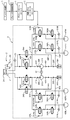
- FIG. 3 is a diagram illustrating a hydraulic circuit in the hydraulic control unit according to the first embodiment.
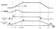
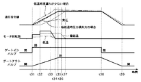
- 2 is a time chart of Example 1.
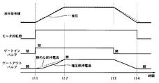
- FIG. It is a time chart of a comparative example.
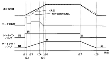
- 6 is a time chart of Example 2.
- 6 is a time chart of Example 3.
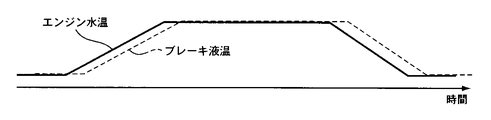
- 6 is a map of an estimated brake fluid temperature with respect to an engine coolant temperature in Example 3.
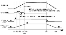
- 10 is a time chart of Example 4.
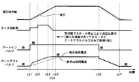
- 10 is a time chart of Example 5.
- 10 is a time chart of Example 6.
- 10 is a flowchart of Example 7.
- 10 is a flowchart of Example 7.
- 10 is a flowchart of Example 7.
- FIG. 1 is a diagram showing a hydraulic circuit in the hydraulic control unit 3.
- the hydraulic control unit 3 has an internal control unit 2.
- the internal control unit 2 controls the motor 32 and each valve based on various information.
- the internal control unit 2 is connected to the ITS control unit 1 through a controller area network (CAN).
- ITS control unit 1 includes Automatic Emergency Braking (AEB), Electronic Stability Control (ESC), Adaptive Cruise Control (ACC) and Lane Departure Prevention (LDP).
- AEB Automatic Emergency Braking
- ESC Electronic Stability Control
- ACC Adaptive Cruise Control
- LDP Lane Departure Prevention
- the target hydraulic pressure of each wheel cylinder 42 is calculated based on the system).
- the ITS control unit 1 receives the estimated brake fluid temperature from the brake fluid temperature estimator 4.
- the brake fluid temperature estimation unit 4 estimates the brake fluid temperature from the value of the engine water temperature meter that measures the temperature of the engine water.
- the hydraulic circuit is divided into two systems, the primary system and the secondary system.
- the primary system is connected to the left front wheel wheel cylinder 42FL and the right rear wheel wheel cylinder 42RR
- the secondary system is connected to the right front wheel wheel cylinder 42FR and the left system.
- a rear wheel wheel cylinder 42RL is connected to form a so-called X pipe.
- P is added to the code of the configuration provided in the primary system
- S is added to the code of the configuration provided in the secondary system, but “P” and “S” are added unless otherwise distinguished. Absent.
- “FL”, “FR”, “RL”, and “RR” are added to the configurations provided for the respective wheels, but “FL”, “FR”, and “RL” are not particularly distinguished.
- ”And“ RR ” are not attached.
- Plunger pumps 31P and 31S are provided in each of the primary system and the secondary system, and the plunger pump 31 is driven by one motor 32.
- the master cylinder 21 is provided with a reservoir tank 24 and stores brake fluid.
- the master cylinder 21 is provided with a master back 22 that is a booster.
- the master cylinder 21 supplies the brake fluid in the reservoir tank 24 into the hydraulic circuit.
- the master cylinder 21 is connected to the left front wheel wheel cylinder 42FL and the right rear wheel wheel cylinder 42RR by a liquid path 45P, and the master cylinder 21 is connected to the right front wheel wheel cylinder 42FR and the left rear wheel wheel cylinder 42RL by a liquid path 45S.
- the liquid passage 45 is provided with gate-out valves 33P and 33S which are normally open proportional valves.
- Bypass passages 46P and 46S that bypass the gate-out valve 33 are formed in the fluid passage 45, and check valves 43P and 43S are provided in the bypass fluid passage 46.
- the check valve 43 allows the flow of brake fluid from the master cylinder 21 toward the wheel cylinder 42, and prohibits the flow on the opposite side.
- Solenoid in valves 35FL, 35FR, 35RL, and 35RR which are normally open proportional valves, are provided on the liquid passage 45 and between the gate-out valve 33 and the wheel cylinders 42.
- Bypass passages 47FL, 47FR, 47RL, and 47RR that bypass the solenoid-in valve 35 are formed in the fluid passage 45, and check valves 37FL, 37FR, 37RL, and 37RR are provided in the bypass passage 47.
- the check valve 37 allows the flow of brake fluid from the wheel cylinder 42 toward the master cylinder 21 and prohibits the flow on the opposite side.
- the master cylinder 21 and the suction side of the plunger pump 31 are connected by liquid passages 48P and 48S.
- the liquid passage 48 is provided with gate-in valves 34P and 34S that are normally closed on / off valves.
- suction valves 40P and 40S are provided on the fluid path 48 between the plunger pump 31 and the gate-in valve 34.
- the suction valve 40 allows the brake fluid to flow toward the side sucked into the plunger pump 31. And prohibit the flow on the opposite side.
- the plunger pump 31 is connected by liquid passages 49P and 49S.
- Discharge valves 41P and 41S are provided in the liquid passage 49.
- the discharge valve 41 allows the flow of brake fluid discharged from the plunger pump 31 and prohibits the flow on the opposite side.
- a master cylinder fluid pressure sensor 25 is provided on the primary side fluid passage 45P and between the master cylinder 21 and the gate-out valve 33P.
- the master cylinder hydraulic pressure sensor 25 may be provided in the master cylinder 21 without being provided in the hydraulic pressure control unit 3.
- Wheel cylinder hydraulic pressure sensors 51FL, 51FR, 51RL, and 51RR are provided on the fluid path 45 and between the wheel cylinder 42 and the solenoid-in valve 35.
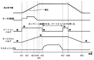
- FIG. 2 is a time chart showing the hydraulic pressure command value calculated by the ITS control unit 1 during ACC or LDP, the motor speed, the control current of the gate-in valve 34, and the control current of the gate-out valve 33.
- the hydraulic pressure command value starts to increase.
- the gate-in valve 34 is opened.
- the motor 32 rotates and the plunger pump 31 is driven.
- the rotation speed of the motor 32 is set so that the plunger pump 31 can generate a hydraulic pressure corresponding to the hydraulic pressure command value.
- the gate-out valve 33 is prevented from opening even at a fluid pressure slightly higher than the fluid pressure command value, and the brake fluid leakage control by the gate-out valve 33 is not performed.
- the rotation speed of the motor 32 is increased.
- the rotational speed of the motor 32 is set so that the plunger cylinder 31 can generate a wheel cylinder hydraulic pressure higher than the hydraulic pressure command value.
- the gate-out valve 33 is opened when the hydraulic pressure becomes higher than the hydraulic pressure command value, and the brake fluid leakage control is performed by the gate-out valve 33.
- FIG. 3 is a time chart showing a comparative example of the first embodiment.
- FIG. 3 shows the hydraulic pressure command value calculated by the ITS control unit 1 during ACC or LDP, the motor speed, the control current of the gate-in valve 34, and the control current of the gate-out valve 33, as in FIG.
- the hydraulic pressure command value starts to increase.
- the gate-in valve 34 is opened.
- the motor 32 rotates and the plunger pump 31 is driven.
- the rotational speed of the motor 32 is set to be higher than the rotational speed of the motor 32 of the first embodiment.
- the gate-out valve 33 is opened when the hydraulic pressure becomes higher than the hydraulic pressure command value, and the brake fluid leakage control is performed by the gate-out valve 33. That is, the gate-out valve 33 is controlled by the pressure increase holding current that is lower than the control current (static holding current) that can always be closed.
- the hydraulic pressure command value becomes constant, the gate-in valve 34 is closed, and the gate-out valve 33 is also completely closed.
- the motor 32 continues to rotate after time t12, the brake fluid is not supplied from the reservoir tank 24 and the hydraulic pressure does not increase because the gate-in valve 34 is closed. Since the hydraulic pressure command value decreases at time t13, the control current of the gate-out valve 33 is reduced according to the hydraulic pressure command value.
- the hydraulic pressure command value becomes zero, and the gate-out valve 33 is completely opened. Further, the motor 32 is stopped.
- the motor 32 is always rotated when the hydraulic pressure command value is generated.
- the hydraulic pressure control is more accurate when the brake fluid leakage control is performed by the gate-out valve 33 than by the rotation speed of the plunger pump 31.
- the motor 32 is set to a high rotational speed to such an extent that the hydraulic pressure can be generated higher than the required hydraulic pressure.
- a loud driving sound is generated, which may cause discomfort to the passenger.
- the gate-out valve 33 is controlled to be closed at the initial stage of braking (time t1 to time t2), and the brake fluid leakage control by the gate-out valve 33 is not performed (first pressure increase). . Since the brake fluid leakage control is not performed, the rotation speed of the motor 32 can be reduced.
- the initial stage of braking indicates a period until braking force is generated in the vehicle. During this period, since the brake disc and the brake pad are not in contact, noise other than the driving sound of the motor 32 and the plunger pump 31 is small, and the driving sound of the motor 32 and the plunger pump 31 tends to be worrisome for the passenger.
- the braking force is not yet generated, it is also a period in which the hydraulic pressure control is not required with high accuracy. Therefore, by stopping the brake fluid leakage control as described above and reducing the rotation speed of the motor 32, it is possible to suppress noise generated by the motor 32 and the plunger pump 31 during a period in which the passenger is likely to be harsh.
- the gate-out valve 33 is controlled to open and close, and the brake fluid leakage control by the gate-out valve 33 is performed (second pressure increase).
- the brake disc and the brake pad are in contact with each other, so that noise other than the driving sound of the motor 32 and the plunger pump 31 is generated. That is, it is in a state where it is difficult for passengers to be concerned about noise from the motor 32 and the plunger pump 31.
- brake fluid leakage control with high accuracy of hydraulic pressure control is performed.
- a fluid path 45 (first hydraulic circuit) that connects the master cylinder 21 and the wheel cylinder 42 disposed on each wheel; a downstream side that is provided in the fluid path 45 and that is connected to the wheel cylinder 42 side;
- a gate-out valve 33 (differential pressure valve) that adjusts the differential pressure between the upstream side connected to the master cylinder 21 side and a plunger that discharges brake fluid between the gate-out valve 33 and the wheel cylinder 42 in the fluid path 45
- ITS control unit 1 hydroaulic pressure) that increases the hydraulic pressure of the wheel cylinder provided on the wheel based on the braking force command calculated according to the vehicle or wheel state by the pump 31 (pump), the gate-out valve 33 and the plunger pump 31
- the ITS control unit 1 includes a first booster that closes the gate-out valve 33 and drives the plunger pump 31 to increase the wheel cylinder hydraulic pressure, and the gate-out valve.
- the second pressure increase which increases the wheel cylinder hydraulic pressure by driving the plunger pump 31 while allowing the brake fluid to leak from the downstream side to the upstream side of the fluid passage 45 by the hub 33, is switched in the state of the vehicle. I did it. Thereby, at the time of the first pressure increase, the generation of noise due to the pulse pressure of the plunger pump 31 can be suppressed. Further, at the time of the second pressure increase, the accuracy of the hydraulic pressure control can be increased. (2) The ITS control unit 1 performs the first pressure increase for a predetermined period from the start of control. Therefore, it is possible to suppress noise generated by the motor 32 and the plunger pump 31 during a period in which the passenger is likely to be harsh.
- the predetermined period from the start of the control for performing the first pressure increase is defined as the period until the actual braking force is generated in the vehicle. It is possible to suppress the driving noise of the motor 32 and the plunger pump 31 during a period when the driving noise of the motor 32 and the plunger pump 31 is likely to be worrisome for the passenger.
- FIG. 4 is a time chart showing the hydraulic pressure command value calculated by the ITS control unit 1 during ACC or LDP, the motor speed, the control current of the gate-in valve 34, and the control current of the gate-out valve 33. At time t21, the hydraulic pressure command value starts to increase. When the hydraulic pressure command value increases, the gate-in valve 34 is opened.
- the motor 32 rotates and the plunger pump 31 is driven.
- the rotation speed of the motor 32 is set to a higher rotation speed than that in the first pressure increase and the second pressure increase performed in the first embodiment.
- the rotational speed of the motor 32 is decreased.
- the rotation speed of the motor 32 is set so that the plunger pump 31 can generate a hydraulic pressure corresponding to the hydraulic pressure command value.
- the gate-out valve 33 is prevented from opening even at a fluid pressure slightly higher than the fluid pressure command value, and the brake fluid leakage control by the gate-out valve 33 is not performed.
- the rotation speed of the motor 32 is increased.
- the rotational speed of the motor 32 is set so that the plunger cylinder 31 can generate a wheel cylinder hydraulic pressure higher than the hydraulic pressure command value.
- the gate-out valve 33 is opened when the hydraulic pressure becomes higher than the hydraulic pressure command value, and the brake fluid leakage control is performed by the gate-out valve 33.
- the rotational speed of the motor 32 is reduced.
- the hydraulic pressure command value becomes constant, the gate-out valve 33 is completely closed, and the hydraulic pressure is maintained.
- the rotation speed of the motor 32 is set to be higher than that during the first pressure increase and the second pressure increase in a predetermined period (time t21 to time t22) from the start of braking. That is, the number of rotations of the plunger pump 31 is also controlled to be higher than that during the first pressure increase and the second pressure increase.
- backlash between the brake pad and the brake disk can be performed at the start of braking, and a response delay in increasing the brake fluid pressure can be suppressed.
- the ITS control unit 1 controls the rotation speed of the plunger pump 31 so that the rotation speed is higher than that at the time of the first pressure increase and the second pressure increase for a predetermined period from the start of control. did.
- the predetermined period during which the number of rotations of the plunger pump 31 is controlled to be higher than that at the time of the first pressure increase and the second pressure increase is a period during which the clearance generated between the brake disc and the brake pad is reduced. . Since the rotation speed of the plunger pump 31 is increased only for a short time when the brake disc and the brake pad are padded, generation of a loud driving sound by the motor 32 and the plunger pump 31 can be made only for a short time.
- Example 3 The third embodiment is different from the first embodiment in the control method of the motor 32. About the same structure as Example 1, the same code
- the setting of the rotational speed of the motor 32 is changed according to the brake fluid temperature.
- FIG. 5 is a time chart showing the hydraulic pressure command value calculated by the ITS control unit 1 during ACC or LDP, the motor speed, the control current of the gate-in valve 34, and the control current of the gate-out valve 33.
- the hydraulic pressure command value starts to increase.
- the gate-in valve 34 is opened. Then, the motor 32 rotates and the plunger pump 31 is driven.
- the rotation speed of the motor 32 is set so that the plunger pump 31 can generate a hydraulic pressure corresponding to the hydraulic pressure command value.
- the number of revolutions of the motor 32 is set to be highest at normal temperature, next highest at extremely low temperatures, and lowest at low temperatures.
- the gate-out valve 33 is prevented from opening even at a fluid pressure slightly higher than the fluid pressure command value, and the brake fluid leakage control by the gate-out valve 33 is not performed.
- the rotational speed of the motor 32 is increased.
- the rotational speed of the motor 32 is set so that the plunger cylinder 31 can generate a wheel cylinder hydraulic pressure higher than the hydraulic pressure command value.
- the gate-out valve 33 is opened when the hydraulic pressure becomes higher than the hydraulic pressure command value, and the brake fluid leakage control is performed by the gate-out valve 33.
- the actual pressure has approached the hydraulic pressure command value at normal temperature and low temperature, so the rotational speed of the motor 32 is reduced.
- the rotation of the motor 32 is stopped because the actual pressure substantially coincides with the hydraulic pressure command value at normal temperature and low temperature.
- the hydraulic pressure command value becomes constant, the gate-out valve 33 is completely closed, and the hydraulic pressure is maintained.
- the rotational speed of the motor 32 is decreased.
- the rotation of the motor 32 is stopped at an extremely low temperature.
- the gate-in valve 34 is closed, and the control current of the gate-out valve 33 is reduced according to the hydraulic pressure command value.
- the hydraulic pressure command value becomes zero, and the gate-out valve 33 is completely opened.
- FIG. 6 is a graph showing an estimated value of the brake fluid temperature with respect to the engine water temperature.
- the brake fluid temperature is estimated from the engine water temperature. Since the brake fluid temperature changes with a delay with respect to the engine coolant temperature, the estimated value of the brake fluid temperature is set so as to change with a delay with respect to the engine coolant temperature as shown in FIG. [Action]
- Example 3 when the brake fluid temperature is low and extremely low, the engine speed is set lower than that at normal temperature. That is, the rotation speed of the plunger pump 31 is also controlled to be lower than that at normal temperature.
- the brake fluid temperature is high, the viscosity of the brake fluid is low and leakage from the plunger pump 31 is large.
- the brake fluid temperature when the brake fluid temperature is low, the viscosity of the brake fluid is high and leakage from the plunger pump 31 is small. If the rotation speed of the plunger pump 31 is set to the same rotation speed as that at the normal temperature at a low temperature or an extremely low temperature, the actual brake fluid becomes too high with respect to the brake fluid pressure command value. When the brake fluid temperature is low and extremely low, the number of revolutions of the plunger pump 31 is controlled to be low so that the brake fluid discharge amount can be adjusted according to the brake fluid leakage amount from the plunger pump 31.
- Example 3 when the brake fluid temperature is extremely low, the engine speed is set higher than when the brake fluid temperature is low. That is, the rotation speed of the plunger pump 31 is also controlled to be higher than when the temperature is low.
- the brake fluid temperature becomes extremely low, the viscosity of the brake fluid is high and cannot be smoothly drawn into the plunger pump 31. Therefore, the brake fluid rises slowly.
- the brake fluid temperature is extremely low, the rise of the brake fluid pressure can be accelerated by controlling the rotation speed of the plunger pump 31 to be higher.
- the brake fluid temperature was estimated from the engine water temperature. Since the brake fluid temperature can be estimated using the engine water temperature gauge 5 normally provided in the engine, it is not necessary to separately provide a device for measuring the brake fluid temperature, and the number of parts can be suppressed.
- the brake fluid temperature estimation unit 4 for estimating the brake fluid temperature is provided, and the ITS control unit 1 determines that the estimated brake fluid temperature is a predetermined value when the estimated brake fluid temperature is a low temperature below a predetermined brake fluid temperature.
- the number of revolutions of the pump is set lower than when the temperature is higher than the brake fluid temperature. Therefore, the brake fluid discharge amount can be adjusted according to the brake fluid leakage amount from the plunger pump 31.
- the brake fluid temperature estimation unit 4 estimates the brake fluid temperature based on the water temperature of the engine mounted on the vehicle. Therefore, it is not necessary to separately provide a device for measuring the brake fluid temperature, and the number of parts can be suppressed.
- Example 4 The fourth embodiment is different from the first embodiment in the control method of the motor 32. About the same structure as Example 1, the same code
- the setting of the rotational speed of the motor 32 is changed according to the wheel cylinder hydraulic pressure.
- FIG. 7 is a time chart showing the hydraulic pressure command value calculated by the ITS control unit 1 during ACC or LDP, the motor speed, the control current of the gate-in valve 34, and the control current of the gate-out valve 33. At time t41, the hydraulic pressure command value starts to increase. When the hydraulic pressure command value increases, the gate-in valve 34 is opened.
- the motor 32 rotates and the plunger pump 31 is driven.
- the rotation speed of the motor 32 is set so that the plunger pump 31 can generate a hydraulic pressure corresponding to the hydraulic pressure command value.
- the gate-out valve 33 is prevented from opening even at a fluid pressure slightly higher than the fluid pressure command value, and the brake fluid leakage control by the gate-out valve 33 is not performed.
- the rotation speed of the motor 32 is increased.
- a limiter is provided for the change speed.
- the rotational speed of the motor 32 is set so that the plunger cylinder 31 can generate a wheel cylinder hydraulic pressure higher than the hydraulic pressure command value.
- the gate-out valve 33 is opened when the hydraulic pressure becomes higher than the hydraulic pressure command value, and the brake fluid leakage control is performed by the gate-out valve 33.
- the actual pressure (foil cylinder pressure) becomes equal to or higher than a predetermined hydraulic pressure.
- the motor 32 is decreased by a predetermined number of rotations.
- a limiter is provided for the change speed.
- Example 4 when the wheel cylinder hydraulic pressure becomes equal to or higher than the predetermined hydraulic pressure during the second pressure increase (time t42 to time t43) (time t43), the rotational speed of the motor 32 is set low. That is, the rotation speed of the plunger pump 31 is also controlled to be low.
- the wheel cylinder hydraulic pressure increases, the load on the motor 32 increases, and vibrations increase and noise is generated if the rotational speed is maintained.
- the wheel cylinder hydraulic pressure is a predetermined hydraulic pressure, noise can be suppressed by setting the rotational speed of the motor 32 low.
- a limiter is provided for the change speed of the rotational speed. Thereby, it is possible to suppress a sense of discomfort to the driver due to a sudden change in the rotational speed of the motor 32.
- a wheel cylinder hydraulic pressure sensor 51 (foil cylinder hydraulic pressure calculation unit) that calculates the hydraulic pressure of the wheel cylinder is provided, and the ITS control unit 1 is configured such that the wheel cylinder hydraulic pressure calculated during the second pressure increase is a predetermined value.
- the rotation speed of the plunger pump 31 is decreased by a predetermined rotation speed. Thereby, noise can be suppressed.
- Example 5 The fifth embodiment is different from the first embodiment in the control method of the motor 32. About the same structure as Example 1, the same code
- the control current of the gate-out valve 33 is set to be high at the time of the first pressure increase.
- FIG. 8 is a time chart showing the hydraulic pressure command value calculated by the ITS control unit 1 during ACC or LDP, the motor speed, the control current of the gate-in valve 34, and the control current of the gate-out valve 33. At time t51, the hydraulic pressure command value starts to increase. When the hydraulic pressure command value increases, the gate-in valve 34 is opened.
- the motor 32 rotates and the plunger pump 31 is driven.
- the rotation speed of the motor 32 is set so that the plunger pump 31 can generate a hydraulic pressure corresponding to the hydraulic pressure command value.
- the gate-out valve 33 is set to a command value (static holding current command value) higher than the hydraulic pressure command value (holding current command value during pressure increase) of the first embodiment.
- the rotation speed of the motor 32 is increased.
- the rotational speed of the motor 32 is set so that the plunger cylinder 31 can generate a wheel cylinder hydraulic pressure higher than the hydraulic pressure command value.
- the gate-out valve 33 is opened when the hydraulic pressure becomes higher than the hydraulic pressure command value, and the brake fluid leakage control is performed by the gate-out valve 33.
- the rotational speed of the motor 32 is decreased.
- the plunger pump 31 also stops, but the gate-in valve 34 remains open.
- the hydraulic pressure command value becomes constant, the gate-out valve 33 is completely closed, and the hydraulic pressure is maintained.
- the gate-in valve 34 is closed, and the control current of the gate-out valve 33 is reduced according to the hydraulic pressure command value.
- the hydraulic pressure command value becomes zero, and the gate-out valve 33 is completely opened.
- Example 5 the control current of the gate-out valve 33 during the first pressure increase (time t51 to time t52) was increased. This suppresses leakage of brake fluid from the gate-out valve 33 during the first pressure increase in which the wheel cylinder pressure is controlled not by the leakage control by the gate-out valve 33 but by the rotation speed control of the plunger pump 31. Can do. Therefore, the rotation speed of the plunger pump 31 can be suppressed and generation of noise can be suppressed.
- the gate-in valve 34 is kept open even when the plunger pump 31 is stopped (time t54 to time t56). Sound is generated when the gate-in valve 34 opens and closes. Noise can be suppressed by reducing the number of open / close valves of the gate-in valve 34.
- FIG. 9 is a time chart showing the hydraulic pressure command value calculated by the ITS control unit 1 during ACC or LDP, the motor speed, the control current of the gate-in valve 34, the control current of the gate-out valve 33, and the master cylinder pressure. .
- the hydraulic pressure command value starts to increase.
- the gate-in valve 34 is opened.
- the motor 32 rotates and the plunger pump 31 is driven.
- the rotation speed of the motor 32 is set so that the plunger pump 31 can generate a hydraulic pressure corresponding to the hydraulic pressure command value.
- the gate-out valve 33 is prevented from opening even at a fluid pressure slightly higher than the fluid pressure command value, and the brake fluid leakage control by the gate-out valve 33 is not performed.
- the rotation speed of the motor 32 is increased.
- the rotational speed of the motor 32 is set so that the plunger cylinder 31 can generate a wheel cylinder hydraulic pressure higher than the hydraulic pressure command value.
- the gate-out valve 33 is opened when the hydraulic pressure becomes higher than the hydraulic pressure command value, and the brake fluid leakage control is performed by the gate-out valve 33.
- the control current of the gate-in valve 34 is turned on, and the gate-in valve 34 is opened.
- the gate-in valve 34 is closed, and the control current of the gate-out valve 33 is reduced according to the hydraulic pressure command value.
- the hydraulic pressure command value becomes zero, and the gate-out valve 33 is completely opened.
- the gate-in valve 34 is closed when the brake pedal 20 is depressed by the driver when the hydraulic pressure is maintained and the master cylinder hydraulic pressure increases.
- the seal in the plunger pump 31 may be broken.
- closing the gate-in valve 34 prevents a large hydraulic pressure from acting on the plunger pump 31 and suppresses breakage of the seal.
- FIG. 10 is a flowchart showing a flow of control of the wheel cylinder hydraulic pressure of each wheel.
- the ITS control unit 1 calculates the target hydraulic pressure of each wheel cylinder 42 based on AEB, ESC, ACC, and LDP, and proceeds to step S2.
- the target hydraulic pressure of each wheel cylinder 42 is sent to the internal control unit 2 by CAL, and the process proceeds to step S3.
- step S3 the internal control unit 2 performs a hydraulic pressure distribution process to each wheel, and the process proceeds to step S4.
- step S4 the drive processing of each valve and motor 32 in the hydraulic pressure control unit 3 is performed, and the processing ends.
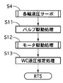
- FIG. 11 is a flowchart showing the flow of the drive processing of each valve and motor 32 in step 4.
- step S11 each valve is driven, and the process proceeds to step S12.
- step S12 the drive process of the motor 32 is performed, and the process proceeds to step S13.
- step S13 the wheel cylinder hydraulic pressure is estimated, and the process is terminated.
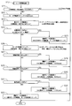
- FIG. 12 is a flowchart showing the flow of the driving process of the motor 32.
- step S21 it is determined whether or not the difference between the target hydraulic pressure of the wheel cylinder 42 and the estimated hydraulic pressure is greater than 0.02 [Mpa]. If greater than 0.02 [Mpa], the process proceeds to step S22, and is less than or equal to 0.02 [Mpa]. If it is, the process is terminated.
- step S22 the rotation speed limiter of the motor 32 is set to 4000 [rpm], and the process proceeds to step S23.
- step S23 the basic motor rotational speed is set by the following equation, and the process proceeds to step S24.
- Basic motor speed (Target hydraulic pressure-Estimated hydraulic pressure) x k1
- the target hydraulic pressure is the target hydraulic pressure of the wheel cylinder 42
- the estimated hydraulic pressure is the estimated hydraulic pressure of the wheel cylinder 42
- k1 is a response-oriented model on the premise of hydraulic leakage control by the gate-out valve 33. It is a coefficient.
- step S24 it is determined whether the target hydraulic pressure of the wheel cylinder 42 is greater than 5 [Mpa], AED, ESC, or high speed traveling, and any of the above-mentioned conditions is determined.
- the process proceeds to step S25, and when neither is established, the process proceeds to step S26.
- step S25 the final motor rotation speed is set to the smaller of the basic motor rotation speed and the rotation speed limiter of the motor 32, and the process is terminated (second pressure increase).
- step S26 the rotational speed limiter of the motor 32 is set by the following equation, and the process proceeds to step S27.
- step S27 it is determined whether or not it is within 20 [ms] from the start of braking. When it is within 20 [ms], the process proceeds to step S28, and when it exceeds 20 [ms], the process proceeds to step S29.
- step S28 the final motor rotational speed is set to the larger one of the basic motor rotational speed and 1500 [ms], and the process ends.
- step S29 it is determined whether or not it is within 100 [ms] from the start of braking. When it is within 100 [ms], the process proceeds to step S30, and when it exceeds 100 [ms], the process proceeds to step S29.
- step S30 the final motor rotational speed is set to the smaller of the basic motor rotational speed and 800 [ms], and the process is terminated (first pressure increase).
- step S31 it is determined whether or not the estimated hydraulic pressure of the wheel cylinder 42 is greater than 2 [Mpa].
- step S32 the final motor rotation speed is set to the smaller of the basic motor rotation speed and 1100 [ms], and the process is terminated (second pressure increase).
- step S33 the final motor rotational speed is set to the smaller of the basic motor rotational speed and the motor rotational speed limiter, and the process ends.
- Example 7 when the target hydraulic pressure of the wheel cylinder 42 is larger than 5 [MPa], or during AEB or ESC, the motor 32 is controlled by the basic motor rotation speed (step S24 ⁇ step S25). . At this time, the gate-out valve 33 is controlled to open and close to control the leakage of the hydraulic pressure, and the second pressure increase is performed. If the determination condition in step S24 is not satisfied, only one or both of ACC and LDP are performed. Further, when the target hydraulic pressure of the wheel cylinder 42 is larger than 5 [MPa], it is determined that the AEB is operating. Thereby, in the case of AEB or ECS with a high degree of urgency, the second pressure increase can be performed, and the wheel cylinder hydraulic pressure can be secured early.
- step S27 when the time is within 20 [ms] from the start of braking, the rotational speed of the motor 32 is set higher (step S27 ⁇ step S28). At this time, the gate-out valve 33 is maintained in the closed state so that the hydraulic pressure leakage control is not performed, and the first pressure increase is performed. As a result, backlash between the brake pad and the brake disk can be performed at the start of braking, and a response delay of the wheel cylinder hydraulic pressure increase can be suppressed.
- the first pressure increase for setting the rotational speed of the motor 32 to be low is performed (step S29 ⁇ step S30).
- the gate-out valve 33 is maintained in the closed state so that the hydraulic pressure leakage control is not performed, and the first pressure increase is performed.
- other noise is small, and the driving sound of the motor 32 tends to be annoying for the occupant.
- the second pressure increase is performed to set the rotation speed of the motor 32 high (step S29 ⁇ step S31 ⁇ step S32 or step S29 ⁇ Step S31 ⁇ Step S33).
- the gate-out valve 33 is controlled to open and close to control the leakage of the hydraulic pressure, and the second pressure increase is performed.
- the second pressure increase is performed at the late stage of braking, it is possible to improve the accuracy of the brake fluid pressure control.
- the ITS control unit 1 executes the first pressure increase when the braking command is at the initial stage of the pressure increase, and executes the second pressure increase at the latter stage of the pressure increase. Therefore, the generation of noise can be suppressed by suppressing the rotational speed of the motor 32 in the early stage of braking. The accuracy of the brake fluid pressure control can be improved in the late braking period. (13) The ITS control unit 1 executes the second pressure increase when the vehicle or the wheel state is the emergency brake state even when the braking command is in the initial stage of the pressure increase. Therefore, the wheel cylinder hydraulic pressure can be secured at an early stage during emergency braking.
- a fluid passage 45 (first fluid pressure circuit) that connects the master cylinder 21 and the wheel cylinder 42 disposed on each wheel; a downstream side that is provided in the fluid passage 45 and is connected to the wheel cylinder 42 side; A gate-out valve 33 (differential pressure valve) that adjusts the differential pressure between the upstream side connected to the master cylinder 21 side, the brake fluid is sucked from the master cylinder 21, and the gate-out valve 33 in the fluid passage 45 and the wheel cylinder 42
- the brake force command calculated according to the vehicle or wheel condition by the plunger pump 31 (pump) that discharges the brake fluid between, the motor 32 that drives the plunger pump 31, the gate-out valve 33 and the plunger pump 31.
- ITS control unit 1 (hydraulic pressure control unit) for increasing and decreasing the wheel cylinder hydraulic pressure provided in the vehicle, and the ITS control unit 1 has a braking force command with a predetermined pressure increase gradient not
- the gate-out valve 33 is controlled in the valve closing direction, and the motor 32 is driven to execute the first pressure increase to increase the wheel cylinder hydraulic pressure according to the rotation speed of the motor 32, and the braking force command Is greater than or equal to a predetermined pressure increase gradient or at a later stage of pressure increase, the motor 32 is set to a predetermined rotation speed or higher and the brake fluid from the downstream side to the upstream side of the first hydraulic pressure circuit is circulated through the gate-out valve 33 to recirculate the motor 32.
- the ITS control unit 1 is in an inter-vehicle distance control state (ACC), a constant speed driving state (ACC), or a lane departure prevention control state (LDP) in which the vehicle or wheel state maintains the inter-vehicle distance from the preceding vehicle at a predetermined distance. At that time, the first pressure increase was performed. Therefore, generation of noise can be suppressed by suppressing the rotation speed of the motor 32.
- the ITS control unit 1 performs the second pressure increase when the vehicle or wheel state is the emergency brake state (AEB, ESC). Therefore, when the degree of urgency is high, the second pressure increase can be performed to ensure the wheel cylinder hydraulic pressure at an early stage.
- a plunger pump 31 (pump) that discharges brake fluid sucked from the master cylinder 21 to a fluid passage 45 (first hydraulic circuit) that connects the master cylinder 21 and a wheel cylinder 42 disposed on each wheel;
- a gate-out valve 33 (differential pressure valve) for adjusting a differential pressure between a downstream side provided in the liquid passage 45 and connected to the wheel cylinder 42 side and an upstream side connected to the master cylinder 21 side, and a plunger pump 31 Brake fluid is discharged between the gate-out valve 33 of the fluid passage 45 and the wheel cylinder 42, and is provided on the wheel based on the braking force command calculated by the plunger pump 31 and the plunger pump 31 according to the vehicle or wheel state.
- ITS control unit 1 (hydraulic pressure control unit) for increasing and decreasing the hydraulic pressure of the wheel cylinder, and the ITS control unit 1 has a first pressure increase and a second pressure increase in response to a braking force command.
- the first pressure increase is performed by controlling the gate-out valve 33 in the closing direction when the braking force command is less than the predetermined pressure increase response requirement, and depending on the rotation speed of the plunger pump 31.
- the wheel cylinder hydraulic pressure is increased, and when the braking force command is higher than the predetermined pressure increase request of the wheel cylinder 42, the motor is set to a predetermined rotation speed or higher and the gate-out valve
- the brake fluid from the downstream side to the upstream side of the fluid passage 45 is recirculated through 33, and the motor 32 is driven to increase the wheel cylinder fluid pressure. Therefore, when the boosting responsiveness requirement is low, the generation of noise can be suppressed by suppressing the rotational speed of the motor 32 at the beginning of braking.
- the boosting responsiveness requirement is high, the accuracy of the brake fluid pressure control can be improved.
- ITS control unit hydraulic pressure control unit
- 4 brake fluid temperature estimation unit 21 master cylinder
- 31 plunger pump plunger pump
- 33 gate-out valve differential pressure valve
- 42 wheel cylinder 45 liquid path (first hydraulic pressure) Circuit
- Foil cylinder hydraulic pressure sensor foil cylinder hydraulic pressure calculator
Landscapes
- Engineering & Computer Science (AREA)
- Physics & Mathematics (AREA)
- Fluid Mechanics (AREA)
- Transportation (AREA)
- Mechanical Engineering (AREA)
- Regulating Braking Force (AREA)
Abstract
騒音を抑制することができるブレーキ制御装置を提供すること。 ブレーキ制御装置は、マスタシリンダとホイルシリンダとの間に配置した差圧弁を閉弁しポンプを駆動してホイルシリンダ液圧を増圧する第一の増圧と、差圧弁によるブレーキ液の漏れを許容しつつ、ポンプを駆動してホイルシリンダ液圧を増圧する第二の増圧とを車両の状態で切り替える。
Description
本発明は、ブレーキ制御装置に関する。
この種の技術としては、下記の特許文献1に記載の技術が開示されている。特許文献1には、ポンプから吐出されるブレーキ液の脈圧による騒音を低減するために脈圧低減手段を設けたものが開示されている。
特許文献1に記載の発明では、脈圧低減手段を新たに設けているため、コストが上昇するおそれがあった。
本発明は、上記問題に着目されたもので、その目的とするところは、新たな装置を追加することなく騒音を抑制することができるブレーキ制御装置を提供することである。
本発明は、上記問題に着目されたもので、その目的とするところは、新たな装置を追加することなく騒音を抑制することができるブレーキ制御装置を提供することである。
上記目的を達成するため、本発明の第一実施形態では、マスタシリンダとホイルシリンダとの間に配置した差圧弁を閉弁しポンプを駆動してホイルシリンダ液圧を増圧する第一の増圧と、差圧弁によるブレーキ液の漏れを許容しつつ、ポンプを駆動してホイルシリンダ液圧を増圧する第二の増圧とを車両の状態で切り替えるようにした。
第二実施形態では、制動力指令が所定の増圧勾配未満または増圧初期のときには、マスタシリンダとホイルシリンダとの間に配置した差圧弁を閉弁方向に制御し、モータを駆動してモータの回転数に応じホイルシリンダ液圧を増圧する第一の増圧を実行し、制動力指令が所定の増圧勾配以上または増圧後期のときにはモータを所定の回転数以上とし差圧弁を介して第一液圧回路の下流側から上流側へのブレーキ液を還流させ、モータを駆動してホイルシリンダ液圧を増圧する第二の増圧を実行するようにした。
第三実施形態では、制動力指令に応じ第一の増圧と第二の増圧を実行し、第一の増圧は、制動力指令がホイルシリンダの昇圧要求が所定の昇圧応答性要求未満のときにはマスタシリンダとホイルシリンダとの間に配置した差圧弁を閉方向に制御し、ポンプの回転数に応じてホイルシリンダ液圧の増圧を実行し、第二の増圧は、制動力指令がホイルシリンダの昇圧要求が所定の昇圧要求以上のときにはモータを所定の回転数以上とし、差圧弁を介して第一液圧回路の下流側から上流側へのブレーキ液を還流させ、モータを駆動してホイルシリンダ液圧の増圧を実行するようにした。
よって、第一実施形態ないし第三実施形態では、第一の増圧のときにはポンプの脈圧による騒音の発生を抑制することができる。また第二の増圧のときには、液圧制御の精度を高めることができる。
〔実施例1〕
実施例1のブレーキ制御装置について説明する。
[液圧コントロールユニットの構成]
図1は液圧コントロールユニット3内の液圧回路を示す図である。液圧コントロールユニット3は、内部コントロールユニット2を有している。内部コントロールユニット2は各種情報に基づいて、モータ32や各バルブを制御する。内部コントロールユニット2は、Controller Area Network (CAN:コントローラエリアネットワーク)によりITSコントロールユニット1と接続している。ITSコントロールユニット1は、Automatic Emergency Braking(AEB:自動緊急ブレーキ)、Electronic Stability Control(ESC:横滑り防止装置)、Adaptive Cruise Control(ACC:車間自動制御システム)、Lane Departure Prevention(LDP:車線逸脱防止支援システム)などに基づいて、各ホイルシリンダ42の目標液圧を演算する。ITSコントロールユニット1は、ブレーキ液温推定部4からブレーキ液温推定値が入力される。ブレーキ液温推定部4は、エンジン水の温度を計測するエンジン水温計の値からブレーキ液温を推定する。
液圧回路はプライマリ系統とセカンダリ系統の2系統に分かれており、プライマリ系統には左フロント輪ホイルシリンダ42FL、右リア輪ホイルシリンダ42RRが接続され、セカンダリ系統には右フロント輪ホイルシリンダ42FR、左リア輪ホイルシリンダ42RLが接続されており、所謂X配管を構成している。以下、プライマリ系統に設けられた構成の符号に「P」を、セカンダリ系統に設けられた構成の符号に「S」を付すが、特に区別しないときには「P」、「S」の符号は付さない。また各車輪に対応して設けられた構成には符号に「FL」、「FR」、「RL」、「RR」を付すが、これも特に区別しないときには「FL」、「FR」、「RL」、「RR」の符号は付さない。
プライマリ系統、セカンダリ系統それぞれにプランジャポンプ31P,31Sが設けられ、プランジャポンプ31は1つのモータ32によって駆動される。
プライマリ系統、セカンダリ系統それぞれにプランジャポンプ31P,31Sが設けられ、プランジャポンプ31は1つのモータ32によって駆動される。
マスタシリンダ21には、リザーバタンク24が設けられ、ブレーキ液が貯留されている。またマスタシリンダ21には、倍力装置であるマスタバック22が設けられている。マスタシリンダ21は、ドライバによりブレーキペダル20が操作されると、リザーバタンク24内のブレーキ液を液圧回路内に供給する。
マスタシリンダ21と左フロント輪ホイルシリンダ42FLおよび右リア輪ホイルシリンダ42RRとは液路45Pによって接続され、マスタシリンダ21と右フロント輪ホイルシリンダ42FRおよび左リア輪ホイルシリンダ42RLとは液路45Sによって接続されている。液路45には常開型の比例弁であるゲートアウトバルブ33P,33Sが設けられている。液路45にはゲートアウトバルブ33を迂回するバイパス液路46P,46Sが形成され、バイパス液路46にチェックバルブ43P,43Sが設けられている。チェックバルブ43はマスタシリンダ21からホイルシリンダ42側へ向かうブレーキ液の流れを許容し、反対側の流れを禁止する。
マスタシリンダ21と左フロント輪ホイルシリンダ42FLおよび右リア輪ホイルシリンダ42RRとは液路45Pによって接続され、マスタシリンダ21と右フロント輪ホイルシリンダ42FRおよび左リア輪ホイルシリンダ42RLとは液路45Sによって接続されている。液路45には常開型の比例弁であるゲートアウトバルブ33P,33Sが設けられている。液路45にはゲートアウトバルブ33を迂回するバイパス液路46P,46Sが形成され、バイパス液路46にチェックバルブ43P,43Sが設けられている。チェックバルブ43はマスタシリンダ21からホイルシリンダ42側へ向かうブレーキ液の流れを許容し、反対側の流れを禁止する。
液路45上であってゲートアウトバルブ33と各ホイルシリンダ42との間には常開型の比例弁であるソレノイドインバルブ35FL,35FR,35RL,35RRが設けられている。液路45にはソレノイドインバルブ35を迂回するバイパス液路47FL,47FR,47RL,47RRが形成され、バイパス液路47にチェックバルブ37FL,37FR,37RL,37RRが設けられている。チェックバルブ37はホイルシリンダ42からマスタシリンダ21側へ向かうブレーキ液の流れを許容し、反対側の流れを禁止する。
マスタシリンダ21とプランジャポンプ31の吸入側とは液路48P,48Sによって接続され、液路48には常閉型のオン・オフ弁であるゲートインバルブ34P,34Sが設けられている。また液路48上であってプランジャポンプ31とゲートインバルブ34との間には吸入バルブ40P,40Sが設けられ、吸入バルブ40はプランジャポンプ31に吸入される側へ向かうブレーキ液の流れを許容し、反対側の流れを禁止する。
液路45のゲートアウトバルブ33とソレノイドインバルブ35との間と、プランジャポンプ31とは液路49P,49Sによって接続され、液路49には吐出バルブ41P,41Sが設けられている。吐出バルブ41はプランジャポンプ31から吐出されるブレーキ液の流れを許容し、反対側の流れを禁止する。
液路45のソレノイドインバルブ35と各ホイルシリンダ42との間と、液路48のゲートインバルブ34と吸入バルブ40との間は液路50P,50Sによって接続され、液路50には常閉型のオン・オフ弁であるソレノイドアウトバルブ36FL,36FR,36RL,36RRが設けられている。また液路50のソレノイドアウトバルブ36と吸入バルブ40との間にはリザーバ38P,38Sが設けられ、リザーバ38よりプランジャポンプ31側にはチェックバルブ39P,39Sが設けられている。チェックバルブ39によってリザーバ38からプランジャポンプ31側へ向かうブレーキ液の流れを許容し、反対側の流れを禁止する。
プライマリ側の液路45P上であって、マスタシリンダ21とゲートアウトバルブ33Pとの間にはマスタシリンダ液圧センサ25が設けられている。マスタシリンダ液圧センサ25は液圧コントロールユニット3内に設けず、マスタシリンダ21内に設けるようにしても良い。
液路45上であって、ホイルシリンダ42とソレノイドインバルブ35との間にはホイルシリンダ液圧センサ51FL,51FR,51RL,51RRが設けられている。
プライマリ側の液路45P上であって、マスタシリンダ21とゲートアウトバルブ33Pとの間にはマスタシリンダ液圧センサ25が設けられている。マスタシリンダ液圧センサ25は液圧コントロールユニット3内に設けず、マスタシリンダ21内に設けるようにしても良い。
液路45上であって、ホイルシリンダ42とソレノイドインバルブ35との間にはホイルシリンダ液圧センサ51FL,51FR,51RL,51RRが設けられている。
[液圧制御]
図2はACCまたはLDP中にITSコントロールユニット1により演算される液圧指令値、モータ回転数、ゲートインバルブ34の制御電流、ゲートアウトバルブ33の制御電流を示すタイムチャートである。
時間t1において、液圧指令値が増加し始める。液圧指令値が増加すると、ゲートインバルブ34を開弁する。そしてモータ32が回転し、プランジャポンプ31が駆動される。モータ32の回転数は、プランジャポンプ31により液圧指令値に応じた液圧を発生させることが可能なように設定する。このとき、ゲートアウトバルブ33は液圧指令値よりも若干高い液圧でも開弁しないようにし、ゲートアウトバルブ33によるブレーキ液漏らし制御は行わないようにしている。
時間t2において、モータ32の回転数を増加させる。モータ32の回転数は、プランジャポンプ31により液圧指令値よりも高いホイルシリンダ液圧を発生させることが可能なように設定する。このとき、ゲートアウトバルブ33は、液圧指令値よりも液圧が高くなると開弁するようになっており、ゲートアウトバルブ33によりブレーキ液漏らし制御が行われている。
時間t3において、実圧が液圧指令値に近づいてきたため、モータ32の回転数を低下させる。
時間t4において、実圧が液圧指令値とほぼ一致したため、モータ32の回転を停止させる。
時間t5において、液圧指令値が一定となり、ゲートアウトバルブ33を完全に閉弁して、液圧を保持する。
時間t6において、液圧指令値が減少するため、ゲートインバルブ34を閉弁し、液圧指令値に応じてゲートアウトバルブ33の制御電流を低下させる。
時間t7において、液圧指令値がゼロになり、ゲートアウトバルブ33を完全に開弁させる。
時間t4において、実圧が液圧指令値とほぼ一致したため、モータ32の回転を停止させる。
時間t5において、液圧指令値が一定となり、ゲートアウトバルブ33を完全に閉弁して、液圧を保持する。
時間t6において、液圧指令値が減少するため、ゲートインバルブ34を閉弁し、液圧指令値に応じてゲートアウトバルブ33の制御電流を低下させる。
時間t7において、液圧指令値がゼロになり、ゲートアウトバルブ33を完全に開弁させる。
[比較例]
図3は実施例1の比較例を示すタイムチャートである。図3は図2と同じく、ACCまたはLDP中にITSコントロールユニット1により演算される液圧指令値、モータ回転数、ゲートインバルブ34の制御電流、ゲートアウトバルブ33の制御電流を示している。
時間t11において、液圧指令値が増加し始める。液圧指令値が増加すると、ゲートインバルブ34を開弁する。そしてモータ32が回転し、プランジャポンプ31が駆動される。モータ32の回転数は、実施例1のモータ32の回転数よりも高い回転数に設定されている。このとき、ゲートアウトバルブ33は、液圧指令値よりも液圧が高くなると開弁するようになっており、ゲートアウトバルブ33によりブレーキ液漏らし制御が行われている。つまり、ゲートアウトバルブ33が常に閉弁可能な制御電流(静的な保持電流)よりも低い、増圧保持電流により制御されている。
時間t12において、液圧指令値が一定となり、ゲートインバルブ34を閉弁し、ゲートアウトバルブ33も完全に閉弁する。時間t12以降もモータ32は回転を続けるが、ゲートインバルブ34が閉弁しているため、リザーバタンク24からブレーキ液が供給されず、液圧が増加することはない。
時間t13において、液圧指令値が減少するため、液圧指令値に応じてゲートアウトバルブ33の制御電流を低下させる。
時間t14において、液圧指令値がゼロになり、ゲートアウトバルブ33を完全に開弁させる。またモータ32を停止させる。
[作用]
比較例においては、液圧指令値が発生しているときにはモータ32を常に回転させている。液圧制御は、プランジャポンプ31の回転数により制御するよりも、ゲートアウトバルブ33によりブレーキ液漏らし制御を行ったほうが精度は高い。しかしブレーキ液漏らし制御では、モータ32は必要とされる液圧よりも高く液圧を発生させることが可能な程度に回転数が高く設定されている。モータ32やプランジャポンプ31の回転数が高い状態では大きな駆動音が発生するため、乗員に不快感を与えるおそれがあった。
そこで実施例1では、制動初期(時間t1~時間t2)においては、ゲートアウトバルブ33を閉弁制御し、ゲートアウトバルブ33によるブレーキ液漏らし制御は行わないようにした(第一の増圧)。ブレーキ液漏らし制御を行わないため、モータ32の回転数を低下させることができる。制動初期は、車両に制動力が発生するまでの間のことを示す。この期間はブレーキディスクとブレーキパッドとが接触していないため、モータ32やプランジャポンプ31の駆動音以外の騒音が小さく、乗員にとってモータ32やプランジャポンプ31の駆動音が気になりやすい。また、まだ制動力が発生していない状態であるため、さほど精度の高く液圧制御が求められない期間でもある。よって、上記のようにブレーキ液漏らし制御をやめ、モータ32の回転数を低下させることにより、乗員にとって耳障りになりやすい期間に、モータ32やプランジャポンプ31により発生する騒音を抑制することができる。
また実施例1では、制動後期(時間t2~時間t5)においては、ゲートアウトバルブ33を開閉弁制御し、ゲートアウトバルブ33によるブレーキ液漏らし制御を行うようにした(第二の増圧)。制動後期では、ブレーキディスクとブレーキパッドが接触しているため、モータ32やプランジャポンプ31の駆動音以外でも騒音が発生している状態である。つまり、乗員にとってモータ32やプランジャポンプ31による騒音が気になりにくい状態である。このときには、液圧制御の精度が高いブレーキ液漏らし制御を行う。
[効果]
(1) マスタシリンダ21と各車輪に配設されたホイルシリンダ42とを接続する液路45(第一液圧回路)と、液路45に設けられ、ホイルシリンダ42側に接続する下流側とマスタシリンダ21側に接続する上流側との間の差圧を調整するゲートアウトバルブ33(差圧弁)と、液路45のゲートアウトバルブ33とホイルシリンダ42との間にブレーキ液を吐出するプランジャポンプ31(ポンプ)と、ゲートアウトバルブ33とプランジャポンプ31によって車両または車輪状態に応じて演算された制動力指令に基づき車輪に設けられたホイルシリンダ液圧を増圧するITSコントロールユニット1(液圧制御部)と、を備え、ITSコントロールユニット1は、ゲートアウトバルブ33を閉弁しプランジャポンプ31を駆動してホイルシリンダ液圧を増圧する第一の増圧と、ゲートアウトバルブ33による液路45の下流側から上流側へのブレーキ液の漏れを許容しつつ、プランジャポンプ31を駆動してホイルシリンダ液圧を増圧する第二の増圧と、を車両の状態で切り替えるようにした。
これにより、第一の増圧のときにはプランジャポンプ31の脈圧による騒音の発生を抑制することができる。また第二の増圧のときには、液圧制御の精度を高めることができる。
(2) ITSコントロールユニット1は、制御開始時から所定の間は第一の増圧を行うようにした。
よって、乗員にとって耳障りになりやすい期間に、モータ32やプランジャポンプ31により発生する騒音を抑制することができる。
(3) 第一の増圧を行う制御開始時から所定の間を、車両に実制動力が発生するまでの間とした。
他の騒音が少なく、乗員にとってモータ32やプランジャポンプ31の駆動音が気になりやすい期間にモータ32やプランジャポンプ31の駆動音を抑えることができる。
〔実施例2〕
実施例2は、実施例1とモータ32の制御方法が異なる。実施例1と同じ構成については、同一の符号を付して説明を省略する。実施例2では、制動開始時にブレーキパッドとブレーキディスクとの間のがた詰めのための制御が行われる。
[液圧制御]
図4はACCまたはLDP中にITSコントロールユニット1により演算される液圧指令値、モータ回転数、ゲートインバルブ34の制御電流、ゲートアウトバルブ33の制御電流を示すタイムチャートである。
時間t21において、液圧指令値が増加し始める。液圧指令値が増加すると、ゲートインバルブ34を開弁する。そしてモータ32が回転し、プランジャポンプ31が駆動される。モータ32の回転数は、実施例1で行った第一の増圧および第二の増圧のときよりも高い回転数に設定される。時間t23において、モータ32の回転数を低下させる。モータ32の回転数は、プランジャポンプ31により液圧指令値に応じた液圧を発生させることが可能なように設定する。このとき、ゲートアウトバルブ33は液圧指令値よりも若干高い液圧でも開弁しないようにし、ゲートアウトバルブ33によるブレーキ液漏らし制御は行わないようにしている。
時間t23において、モータ32の回転数を増加させる。モータ32の回転数は、プランジャポンプ31により液圧指令値よりも高いホイルシリンダ液圧を発生させることが可能なように設定する。このとき、ゲートアウトバルブ33は、液圧指令値よりも液圧が高くなると開弁するようになっており、ゲートアウトバルブ33によりブレーキ液漏らし制御が行われている。
時間t24において、実圧が液圧指令値に近づいてきたため、モータ32の回転数を低下させる。
時間t25において、実圧が液圧指令値とほぼ一致したため、モータ32の回転を停止させる。
時間t26において、液圧指令値が一定となり、ゲートアウトバルブ33を完全に閉弁して、液圧を保持する。
時間t27において、液圧指令値が減少するため、ゲートインバルブ34を閉弁し、液圧指令値に応じてゲートアウトバルブ33の制御電流を低下させる。
時間t28において、液圧指令値がゼロになり、ゲートアウトバルブ33を完全に開弁させる。
時間t24において、実圧が液圧指令値に近づいてきたため、モータ32の回転数を低下させる。
時間t25において、実圧が液圧指令値とほぼ一致したため、モータ32の回転を停止させる。
時間t26において、液圧指令値が一定となり、ゲートアウトバルブ33を完全に閉弁して、液圧を保持する。
時間t27において、液圧指令値が減少するため、ゲートインバルブ34を閉弁し、液圧指令値に応じてゲートアウトバルブ33の制御電流を低下させる。
時間t28において、液圧指令値がゼロになり、ゲートアウトバルブ33を完全に開弁させる。
[作用]
実施例2では、制動開始時から所定期間(時間t21~時間t22)に第一の増圧および第二の増圧のときよりもモータ32の回転数を高く設定するようにした。つまり、プランジャポンプ31の回転数も第一の増圧および第二の増圧のときよりも高く制御するようにした。
これにより、制動開始時にブレーキパッドとブレーキディスクとの間のがた詰めを行うことができ、ブレーキ液圧上昇の応答遅れを抑制することができる。
実施例2では、制動開始時から所定期間(時間t21~時間t22)に第一の増圧および第二の増圧のときよりもモータ32の回転数を高く設定するようにした。つまり、プランジャポンプ31の回転数も第一の増圧および第二の増圧のときよりも高く制御するようにした。
これにより、制動開始時にブレーキパッドとブレーキディスクとの間のがた詰めを行うことができ、ブレーキ液圧上昇の応答遅れを抑制することができる。
[効果]
(4) ITSコントロールユニット1は、制御開始時から所定の間は第一の増圧および第二の増圧のときよりも高い回転数になるようにプランジャポンプ31の回転数を制御するようにした。
これにより、制動開始時にブレーキパッドとブレーキディスクとの間のがた詰めを行うことができ、ブレーキ液圧上昇の応答遅れを抑制することができる。
(5) プランジャポンプ31の回転数を第一の増圧および第二の増圧の時よりも高く制御する所定の期間はブレーキディスクとブレーキパッドの間に発生しているクリアランスを詰める間とした。
ブレーキディスクとブレーキパッドのがた詰めを行う短時間だけプランジャポンプ31の回転数が上昇するため、モータ32やプランジャポンプ31による大きな駆動音の発生を短時間のみとすることができる。
〔実施例3〕
実施例3は、実施例1とモータ32の制御方法が異なる。実施例1と同じ構成については、同一の符号を付して説明を省略する。実施例3では、ブレーキ液温に応じてモータ32の回転数の設定を変えている。
[液圧制御]
図5はACCまたはLDP中にITSコントロールユニット1により演算される液圧指令値、モータ回転数、ゲートインバルブ34の制御電流、ゲートアウトバルブ33の制御電流を示すタイムチャートである。
時間t31において、液圧指令値が増加し始める。液圧指令値が増加すると、ゲートインバルブ34を開弁する。そしてモータ32が回転し、プランジャポンプ31が駆動される。モータ32の回転数は、プランジャポンプ31により液圧指令値に応じた液圧を発生させることが可能なように設定する。モータ32の回転数は常温時が最も高く、極低温時が次に高く、低温時が最も低くなるように設定される。このとき、ゲートアウトバルブ33は液圧指令値よりも若干高い液圧でも開弁しないようにし、ゲートアウトバルブ33によるブレーキ液漏らし制御は行わないようにしている。
時間t32において、モータ32の回転数を増加させる。モータ32の回転数は、プランジャポンプ31により液圧指令値よりも高いホイルシリンダ液圧を発生させることが可能なように設定する。このとき、ゲートアウトバルブ33は、液圧指令値よりも液圧が高くなると開弁するようになっており、ゲートアウトバルブ33によりブレーキ液漏らし制御が行われている。
時間t33において、常温時および低温時には実圧が液圧指令値に近づいてきたため、モータ32の回転数を低下させる。
時間t34において、常温時および低温時には実圧が液圧指令値とほぼ一致したため、モータ32の回転を停止させる。
時間t35において、液圧指令値が一定となり、ゲートアウトバルブ33を完全に閉弁して、液圧を保持する。
時間t36において、極低温時にはモータ32の回転数を低下させる。
時間t37において、極低温時にはモータ32の回転を停止させる。
時間t38において、液圧指令値が減少するため、ゲートインバルブ34を閉弁し、液圧指令値に応じてゲートアウトバルブ33の制御電流を低下させる。
時間t39において、液圧指令値がゼロになり、ゲートアウトバルブ33を完全に開弁させる。
時間t34において、常温時および低温時には実圧が液圧指令値とほぼ一致したため、モータ32の回転を停止させる。
時間t35において、液圧指令値が一定となり、ゲートアウトバルブ33を完全に閉弁して、液圧を保持する。
時間t36において、極低温時にはモータ32の回転数を低下させる。
時間t37において、極低温時にはモータ32の回転を停止させる。
時間t38において、液圧指令値が減少するため、ゲートインバルブ34を閉弁し、液圧指令値に応じてゲートアウトバルブ33の制御電流を低下させる。
時間t39において、液圧指令値がゼロになり、ゲートアウトバルブ33を完全に開弁させる。
[ブレーキ液温推定]
図6はエンジン水温に対するブレーキ液温の推定値を示すグラフである。実施例3では、エンジン水温からブレーキ液温を推定している。ブレーキ液温はエンジン水温に対して遅れて変化するため、図6に示すようにブレーキ液温の推定値もエンジン水温に対して遅れて変化するように設定している。
[作用]
実施例3では、ブレーキ液温が低温および極低温のときには、常温のときよりもエンジン回転数を低く設定するようにした。つまり、プランジャポンプ31の回転数も常温のときよりも低く制御するようにした。
ブレーキ液温が高いときには、ブレーキ液の粘度が低くプランジャポンプ31からの漏れが多い。一方、ブレーキ液温が低いときには、ブレーキ液の粘度が高くプランジャポンプ31からの漏れが少ない。低温時や極低温時に、プランジャポンプ31の回転数を常温時と同じ回転数にすると、ブレーキ液圧指令値に対して実際のブレーキ液が高くなりすぎる。ブレーキ液温が低温および極低温のときには、プランジャポンプ31の回転数を低く制御することによって、プランジャポンプ31からのブレーキ液の漏れ量に応じたブレーキ液の吐出量に調整することができる。
また実施例3では、ブレーキ液温が極低温のときには、低温のときよりもエンジン回転数を高く設定するようにした。つまり、プランジャポンプ31の回転数も低温のときよりも高く制御するようにした。
ブレーキ液温が極低温になるとブレーキ液の粘度が高く、プランジャポンプ31内にスムーズに吸入することができない。そのため、ブレーキ液の立ち上がりが遅くなる。ブレーキ液温が極低温のときには、プランジャポンプ31の回転数を高めに制御することによって、ブレーキ液圧の立ち上がりを速くすることができる。
また実施例3では、ブレーキ液温をエンジン水温から推定するようにした。エンジンに通常設けられているエンジン水温計5を用いてブレーキ液温を推定することができるため、ブレーキ液温を計測する装置を別途設ける必要がなく、部品点数を抑制することができる。
ブレーキ液温が極低温になるとブレーキ液の粘度が高く、プランジャポンプ31内にスムーズに吸入することができない。そのため、ブレーキ液の立ち上がりが遅くなる。ブレーキ液温が極低温のときには、プランジャポンプ31の回転数を高めに制御することによって、ブレーキ液圧の立ち上がりを速くすることができる。
また実施例3では、ブレーキ液温をエンジン水温から推定するようにした。エンジンに通常設けられているエンジン水温計5を用いてブレーキ液温を推定することができるため、ブレーキ液温を計測する装置を別途設ける必要がなく、部品点数を抑制することができる。
[効果]
(6) ブレーキ液温を推定するブレーキ液温推定部4を備え、ITSコントロールユニット1は、推定されたブレーキ液温が所定のブレーキ液温以下の低温時には、推定された前記ブレーキ液温が所定ブレーキ液温より高いときよりも前記ポンプの回転数を低く設定するようにした。
よって、プランジャポンプ31からのブレーキ液の漏れ量に応じたブレーキ液の吐出量に調整することができる。
(7) ブレーキ液温推定部4は、車両に搭載されたエンジンの水温に基づきブレーキ液温を推定するようにした。
よって、ブレーキ液温を計測する装置を別途設ける必要がなく、部品点数を抑制することができる。
(6) ブレーキ液温を推定するブレーキ液温推定部4を備え、ITSコントロールユニット1は、推定されたブレーキ液温が所定のブレーキ液温以下の低温時には、推定された前記ブレーキ液温が所定ブレーキ液温より高いときよりも前記ポンプの回転数を低く設定するようにした。
よって、プランジャポンプ31からのブレーキ液の漏れ量に応じたブレーキ液の吐出量に調整することができる。
(7) ブレーキ液温推定部4は、車両に搭載されたエンジンの水温に基づきブレーキ液温を推定するようにした。
よって、ブレーキ液温を計測する装置を別途設ける必要がなく、部品点数を抑制することができる。
〔実施例4〕
実施例4は、実施例1とモータ32の制御方法が異なる。実施例1と同じ構成については、同一の符号を付して説明を省略する。実施例4では、ホイルシリンダ液圧に応じてモータ32の回転数の設定を変えている。
[液圧制御]
図7はACCまたはLDP中にITSコントロールユニット1により演算される液圧指令値、モータ回転数、ゲートインバルブ34の制御電流、ゲートアウトバルブ33の制御電流を示すタイムチャートである。
時間t41において、液圧指令値が増加し始める。液圧指令値が増加すると、ゲートインバルブ34を開弁する。そしてモータ32が回転し、プランジャポンプ31が駆動される。モータ32の回転数は、プランジャポンプ31により液圧指令値に応じた液圧を発生させることが可能なように設定する。このとき、ゲートアウトバルブ33は液圧指令値よりも若干高い液圧でも開弁しないようにし、ゲートアウトバルブ33によるブレーキ液漏らし制御は行わないようにしている。
時間t42において、モータ32の回転数を増加させる。モータ32の回転数を増加させる際には、変化速度にリミッタを設けている。モータ32の回転数は、プランジャポンプ31により液圧指令値よりも高いホイルシリンダ液圧を発生させることが可能なように設定する。このとき、ゲートアウトバルブ33は、液圧指令値よりも液圧が高くなると開弁するようになっており、ゲートアウトバルブ33によりブレーキ液漏らし制御が行われている。
時間t43において、実圧(ホイルシリンダ圧)が所定の液圧以上になる。このとき、モータ32の所定回転数だけ減少させる。モータ32の回転数を減少させる際には、変化速度にリミッタを設けている。
時間t44において、実圧が液圧指令値に近づいてきたため、モータ32の回転数を低下させる。
時間t45において、実圧が液圧指令値とほぼ一致したため、モータ32の回転を停止させる。
時間t46において、液圧指令値が一定となり、ゲートアウトバルブ33を完全に閉弁して、液圧を保持する。
時間t47において、液圧指令値が減少するため、ゲートインバルブ34を閉弁し、液圧指令値に応じてゲートアウトバルブ33の制御電流を低下させる。
時間t48において、液圧指令値がゼロになり、ゲートアウトバルブ33を完全に開弁させる。
[作用]
実施例4では、第2の増圧時(時間t42~時間t43)にホイルシリンダ液圧が所定液圧以上となると(時間t43)、モータ32の回転数を低く設定するようにした。つまり、プランジャポンプ31の回転数も低く制御するようにした。
ホイルシリンダ液圧が高くなるとモータ32の負荷が増加し、回転数を維持しようとすると振動が大きくなり騒音が発生する。ホイルシリンダ液圧が所定液圧のときには、モータ32の回転数を低く設定することによって、騒音を抑制することができる。
また実施例4では、モータ32の回転数を増減させるとき、回転数の変化速度にリミッタを設けるようにした。
これにより、モータ32の回転数急変による運転者への違和感を抑制することができる。
[効果]
(8) ホイルシリンダの液圧を算出するホイルシリンダ液圧センサ51(ホイルシリンダ液圧算出部)を備え、ITSコントロールユニット1は、第二の増圧時に算出されたホイルシリンダ液圧が所定の液圧以上となるとプランジャポンプ31の回転数を所定の回転数低下させるようにした。
これにより、騒音を抑制することができる。
(8) ホイルシリンダの液圧を算出するホイルシリンダ液圧センサ51(ホイルシリンダ液圧算出部)を備え、ITSコントロールユニット1は、第二の増圧時に算出されたホイルシリンダ液圧が所定の液圧以上となるとプランジャポンプ31の回転数を所定の回転数低下させるようにした。
これにより、騒音を抑制することができる。
〔実施例5〕
実施例5は、実施例1とモータ32の制御方法が異なる。実施例1と同じ構成については、同一の符号を付して説明を省略する。実施例5では、第一の増圧時にはゲートアウトバルブ33の制御電流を高めに設定するようにしている。
[液圧制御]
図8はACCまたはLDP中にITSコントロールユニット1により演算される液圧指令値、モータ回転数、ゲートインバルブ34の制御電流、ゲートアウトバルブ33の制御電流を示すタイムチャートである。
時間t51において、液圧指令値が増加し始める。液圧指令値が増加すると、ゲートインバルブ34を開弁する。そしてモータ32が回転し、プランジャポンプ31が駆動される。モータ32の回転数は、プランジャポンプ31により液圧指令値に応じた液圧を発生させることが可能なように設定する。このとき、ゲートアウトバルブ33は実施例1の液圧指令値(増圧時保持電流指令値)よりも高い指令値(静的な保持電流指令値)に設定されている。
時間t52において、モータ32の回転数を増加させる。モータ32の回転数は、プランジャポンプ31により液圧指令値よりも高いホイルシリンダ液圧を発生させることが可能なように設定する。このとき、ゲートアウトバルブ33は、液圧指令値よりも液圧が高くなると開弁するようになっており、ゲートアウトバルブ33によりブレーキ液漏らし制御が行われている。
時間t53において、実圧が液圧指令値に近づいてきたため、モータ32の回転数を低下させる。
時間t54において、実圧が液圧指令値とほぼ一致したため、モータ32の回転を停止させる。モータ32は回転を停止しためプランジャポンプ31も停止しているが、ゲートインバルブ34は開弁させたままにしておく。
時間t55において、液圧指令値が一定となり、ゲートアウトバルブ33を完全に閉弁して、液圧を保持する。
時間t56において、液圧指令値が減少するため、ゲートインバルブ34を閉弁し、液圧指令値に応じてゲートアウトバルブ33の制御電流を低下させる。
時間t57において、液圧指令値がゼロになり、ゲートアウトバルブ33を完全に開弁させる。
[作用]
実施例5では、第一の増圧時(時間t51~時間t52)のゲートアウトバルブ33の制御電流を高くするようにした。
これにより、ホイルシリンダ圧をゲートアウトバルブ33による漏らし制御ではなく、プランジャポンプ31の回転数制御により制御している第一の増圧時に、ゲートアウトバルブ33からのブレーキ液の漏れを抑制することができる。よって、プランジャポンプ31の回転数を抑制することができ、騒音の発生を抑えることができる。
実施例5では、プランジャポンプ31を停止しているとき(時間t54~時間t56)であっても、ゲートインバルブ34を開弁させたままにするようにした。
ゲートインバルブ34が開閉弁するときには音が生じる。ゲートインバルブ34の開閉弁回数を減らすことうより、騒音を抑制することができる。
[効果]
(9) 第一の増圧時にゲートアウトバルブ33の制御電流を高くするようにした。
よって、プランジャポンプ31の回転数を抑制することができ、騒音の発生を抑えることができる。
(9) 第一の増圧時にゲートアウトバルブ33の制御電流を高くするようにした。
よって、プランジャポンプ31の回転数を抑制することができ、騒音の発生を抑えることができる。
[実施例6]
実施例6は、実施例1とゲートインバルブ34の制御方法が異なる。実施例1と同じ構成については、同一の符号を付して説明を省略する。実施例6では、液圧保持時にマスタシリンダ圧が上昇するとゲートインバルブ34を閉じるようにしている。
[液圧制御]
図9はACCまたはLDP中にITSコントロールユニット1により演算される液圧指令値、モータ回転数、ゲートインバルブ34の制御電流、ゲートアウトバルブ33の制御電流、マスタシリンダ圧を示すタイムチャートである。
時間t61において、液圧指令値が増加し始める。液圧指令値が増加すると、ゲートインバルブ34を開弁する。そしてモータ32が回転し、プランジャポンプ31が駆動される。モータ32の回転数は、プランジャポンプ31により液圧指令値に応じた液圧を発生させることが可能なように設定する。このとき、ゲートアウトバルブ33は液圧指令値よりも若干高い液圧でも開弁しないようにし、ゲートアウトバルブ33によるブレーキ液漏らし制御は行わないようにしている。
時間t62において、モータ32の回転数を増加させる。モータ32の回転数は、プランジャポンプ31により液圧指令値よりも高いホイルシリンダ液圧を発生させることが可能なように設定する。このとき、ゲートアウトバルブ33は、液圧指令値よりも液圧が高くなると開弁するようになっており、ゲートアウトバルブ33によりブレーキ液漏らし制御が行われている。
時間t63において、実圧が液圧指令値に近づいてきたため、モータ32の回転数を低下させる。
時間t64において、実圧が液圧指令値とほぼ一致したため、モータ32の回転を停止させる。ここでモータ32は回転を停止したが、ゲートインバルブ34は開弁したままとなっている。
時間t65において、液圧指令値が一定となり、ゲートアウトバルブ33を完全に閉弁して、液圧を保持する。
時間t66において、運転者がブレーキペダル20を踏み込みマスタシリンダ圧が上昇する。このとき、ゲートインバルブ34の制御電流をオフにして、ゲートインバルブ34を閉弁させる。
時間t67において、運転者がブレーキペダル20を踏み戻しマスタシリンダ圧が低下する。このとき、ゲートインバルブ34の制御電流をオンにして、ゲートインバルブ34を開弁させる。
時間t68において、液圧指令値が減少するため、ゲートインバルブ34を閉弁し、液圧指令値に応じてゲートアウトバルブ33の制御電流を低下させる。
時間t69において、液圧指令値がゼロになり、ゲートアウトバルブ33を完全に開弁させる。
[作用]
実施例6では、液圧保持時に運転者によりブレーキペダル20が踏み込まれ、マスタシリンダ液圧が上昇すると、ゲートインバルブ34を閉弁するようにした。
プランジャポンプ31に大きな液圧が作用するとプランジャポンプ31内のシールが破損するおそれがある。マスタシリンダ液圧が上昇したときには、ゲートインバルブ34を閉弁することによりプランジャポンプ31に大きな液圧が作用することを防ぎ、シールの破損を抑制することができる。
実施例6では、液圧保持時に運転者によりブレーキペダル20が踏み込まれ、マスタシリンダ液圧が上昇すると、ゲートインバルブ34を閉弁するようにした。
プランジャポンプ31に大きな液圧が作用するとプランジャポンプ31内のシールが破損するおそれがある。マスタシリンダ液圧が上昇したときには、ゲートインバルブ34を閉弁することによりプランジャポンプ31に大きな液圧が作用することを防ぎ、シールの破損を抑制することができる。
[効果]
(10) プランジャポンプ31がマスタシリンダ21からブレーキ液を吸入するための液路45および液路49(吸入油路)と、液路45に設けられたゲートインバルブ34(吸入弁)と、を備え、ITSコントロールユニット1は、第一の増圧および第二の増圧ではゲートインバルブ34を開弁状態とし、液圧保持時にはゲートインバルブ34を開閉制御するようにした。
よって、プランジャポンプ31のシールの破損を抑制することができる。
(11) ITSコントロールユニット1は、液圧保持時に運転者によりブレーキペダル20が操作されたことを検出するようにした。
よって、マスタシリンダ液圧が上昇したときにのみゲートインバルブ34を閉弁するようにすることができ、開閉弁時の騒音を抑制することができる。
[実施例7]
実施例7は、実施例1とモータ32の制御方法が異なる。実施例1と同じ構成については、同一の符号を付して説明を省略する。
[液圧制御]
図10は、各輪のホイルシリンダ液圧の制御の流れを示すフローチャートである。
ステップS1では、ITSコントロールユニット1において、AEB、ESC、ACC、LDPに基づいて各ホイルシリンダ42の目標液圧を算出して、ステップS2へ移行する。
ステップS2では、各ホイルシリンダ42の目標液圧をCALにより内部コントロールユニット2に送り、ステップS3へ移行する。
ステップS3では、内部コントロールユニット2において、各輪への液圧配分処理を行い、ステップS4へ移行する。
ステップS4では、液圧コントロールユニット3内の各バルブおよびモータ32の駆動処理を行い、処理を終了する。
図11はステップ4の各バルブおよびモータ32の駆動処理の流れを示すフローチャートである。
ステップS11では、各バルブの駆動処理を行い、ステップS12へ移行する。
ステップS12では、モータ32の駆動処理を行い、ステップS13へ移行する。
ステップS13では、ホイルシリンダ液圧の推定処理を行い、処理を終了する。
図12はモータ32の駆動処理の流れを示すフローチャートである。
ステップS21では、ホイルシリンダ42の目標液圧と推定液圧との差が0.02[Mpa]より大きいか否かを判定し、0.02[Mpa]より大きいときにはステップS22に移行し、0.02[Mpa]以下であるときには処理を終了する。
ステップS22では、モータ32の回転数リミッタを4000[rpm]に設定して、ステップS23へ移行する。
ステップS23では、次の式により基本モータ回転数を設定して、ステップS24へ移行する。
基本モータ回転数 = (目標液圧 - 推定液圧)×k1
上記の式において、目標液圧はホイルシリンダ42の目標液圧を、推定液圧はホイルシリンダ42の推定液圧を、k1はゲートアウトバルブ33による液圧漏らし制御を前提とした応答性重視の係数である。
ステップS24では、ホイルシリンダ42の目標液圧が5[Mpa]より大きい、またはAED中である、またはESC中である、または高速走行中であるか否かを判定し、前述の条件のいずれかが成立するときにはステップS25へ移行し、いずれも成立しないときにはステップS26へ移行する。
ステップS25では、最終モータ回転数を、基本モータ回転数とモータ32の回転数リミッタとのうち小さい方に設定して処理を終了する(第二の増圧)。
ステップS26では、次の式によりモータ32の回転数リミッタを設定して、ステップS27へ移行する。
モータ回転数リミッタ = (目標液圧 - 推定液圧)×k2
上記式において、k2はモータ32の駆動力のみで昇圧可能な差圧と剛性マップとから求めた係数である。
ステップS27では、制動開始から20[ms]以内であるか否かを判定し、20[ms]以内であるときにはステップS28に移行し、20[ms]を越えているときにはステップS29へ移行する。
ステップS25では、最終モータ回転数を、基本モータ回転数とモータ32の回転数リミッタとのうち小さい方に設定して処理を終了する(第二の増圧)。
ステップS26では、次の式によりモータ32の回転数リミッタを設定して、ステップS27へ移行する。
モータ回転数リミッタ = (目標液圧 - 推定液圧)×k2
上記式において、k2はモータ32の駆動力のみで昇圧可能な差圧と剛性マップとから求めた係数である。
ステップS27では、制動開始から20[ms]以内であるか否かを判定し、20[ms]以内であるときにはステップS28に移行し、20[ms]を越えているときにはステップS29へ移行する。
ステップS28では、最終モータ回転数を、基本モータ回転数と1500[ms]とのうち大きい方に設定し処理を終了する。
ステップS29では、制動開始から100[ms]以内であるか否かを判定し、100[ms]以内であるときにはステップS30に移行し、100[ms]を越えているときにはステップS29へ移行する。
ステップS30では、最終モータ回転数を、基本モータ回転数と800[ms]とのうち小さい方に設定し処理を終了する(第一の増圧)。
ステップS31では、ホイルシリンダ42の推定液圧が2[Mpa]より大きいか否かを判定し、2[MPa]より大きいときにはステップS32に移行し、2[MPa]未満のときにステップ33へ移行する。
ステップS32では、最終モータ回転数を、基本モータ回転数と1100[ms]とのうち小さい方に設定し処理を終了する(第二の増圧)。
ステップS33では、最終モータ回転数を、基本モータ回転数とモータ回転数リミッタのうち小さい方に設定して処理を終了する。
[作用]
実施例7では、ホイルシリンダ42の目標液圧が5[MPa]より大きいとき、またはAEB中、またはESC中にはモータ32を基本モータ回転数により制御するようにした(ステップS24→ステップS25)。このときゲートアウトバルブ33を開閉弁制御して液圧の漏らし制御を行い、第二の増圧が行われている。なお、ステップS24の判定条件を満たさなかったときは、ACCとLDPの一方、または両方のみが行われている。またホイルシリンダ42の目標液圧が5[MPa]より大きいときにはAEBが作動していると判断している。
これにより、緊急度が高いAEBやECSのときには第二の増圧を行い、ホイルシリンダ液圧を早期に確保するようにすることができる。
また実施例7では、制動開始から20[ms]以内であるときには、モータ32の回転数を高めに設定するようにした(ステップS27→ステップS28)。このときゲートアウトバルブ33は閉弁状態を維持して液圧漏らし制御を行わないようにし、第一の増圧が行われている。
これにより、制動開始時にブレーキパッドとブレーキディスクとの間のがた詰めを行うことができ、ホイルシリンダ液圧上昇の応答遅れを抑制することができる。
また実施例7では、制動開始から20[ms]を越え100[ms]以内であるときには、モータ32の回転数を低めに設定する第一の増圧を行うようにした(ステップS29→ステップS30)。このときゲートアウトバルブ33は閉弁状態を維持して液圧漏らし制御を行わないようにし、第一の増圧が行われている。
制動初期には、他の騒音が小さく乗員にとってモータ32の駆動音が耳障りになりやすい。制動初期にモータ32の回転数を抑えることにより、騒音の発生を抑制できる。
また実施例7では、制動開始から100[ms]を越えたときには、モータ32の回転数を高く設定する第二の増圧を行うようにした(ステップS29→ステップS31→ステップS32またはステップS29→ステップS31→ステップS33)。このときゲートアウトバルブ33を開閉弁制御して液圧の漏らし制御を行い、第二の増圧が行われている。
制動後期には、他の騒音も大きく乗員にとってモータ32の駆動音は相対的に小さく聞こえる。制動後期には第二の増圧を行うことにより、ブレーキ液圧制御の精度を向上させることができる。
[効果]
(12) ITSコントロールユニット1は、制動指令が増圧初期のときには第一の増圧を実行し、増圧後期のときには第二の増圧を実行するようにした。
よって、制動初期にモータ32の回転数を抑えることにより、騒音の発生を抑制できる。制動後期にはブレーキ液圧制御の精度を向上させることができる。
(13) ITSコントロールユニット1は、制動指令が増圧初期であっても、車両または車輪状態が緊急ブレーキ状態のときには第二の増圧を実行するようにした。
よって、緊急ブレーキのときにはホイルシリンダ液圧を早期に確保するようにすることができる。
(12) ITSコントロールユニット1は、制動指令が増圧初期のときには第一の増圧を実行し、増圧後期のときには第二の増圧を実行するようにした。
よって、制動初期にモータ32の回転数を抑えることにより、騒音の発生を抑制できる。制動後期にはブレーキ液圧制御の精度を向上させることができる。
(13) ITSコントロールユニット1は、制動指令が増圧初期であっても、車両または車輪状態が緊急ブレーキ状態のときには第二の増圧を実行するようにした。
よって、緊急ブレーキのときにはホイルシリンダ液圧を早期に確保するようにすることができる。
(14) マスタシリンダ21と各車輪に配設されたホイルシリンダ42とを接続する液路45(第一液圧回路)と、液路45に設けられ、ホイルシリンダ42側に接続する下流側とマスタシリンダ21側に接続する上流側との間の差圧を調整するゲートアウトバルブ33(差圧弁)と、マスタシリンダ21からブレーキ液を吸入し、液路45のゲートアウトバルブ33とホイルシリンダ42との間にブレーキ液を吐出するプランジャポンプ31(ポンプ)と、プランジャポンプ31を駆動するモータ32と、ゲートアウトバルブ33とプランジャポンプ31によって車両または車輪状態に応じて演算された制動力指令に基づき車両に設けられたホイルシリンダ液圧の増減圧を行うITSコントロールユニット1(液圧制御部)と、を備え、ITSコントロールユニット1は、制動力指令が所定の増圧勾配未満または増圧初期のときにはゲートアウトバルブ33を閉弁方向に制御し、モータ32を駆動してモータ32の回転数に応じホイルシリンダ液圧を増圧する第一の増圧を実行し、制動力指令が所定の増圧勾配以上または増圧後期のときにはモータ32を所定の回転数以上としゲートアウトバルブ33を介して第一液圧回路の下流側から上流側へのブレーキ液を還流させ、モータ32をしてホイルシリンダ液圧を増圧する第二の増圧を実行するようにした。
よって、制動初期にモータ32の回転数を抑えることにより、騒音の発生を抑制できる。制動後期にはブレーキ液圧制御の精度を向上させることができる。
(15)ITSコントロールユニット1は、車両または車輪状態が前車との車間距離を所定距離に維持する車間距離制御状態(ACC)または定速走行状態(ACC)または車線逸脱防止制御状態(LDP)のときに第一の増圧を実行するようにした。
よって、モータ32の回転数を抑えることにより、騒音の発生を抑制できる。
(16) ITSコントロールユニット1は、車両または車輪状態が緊急ブレーキ状態(AEB,ESC)のときに第二の増圧を実行するようにした。
よって、緊急度が高いときには第二の増圧を行い、ホイルシリンダ液圧を早期に確保するようにすることができる。
(17) マスタシリンダ21から吸入したブレーキ液をマスタシリンダ21と各車輪に配設されたホイルシリンダ42とを接続する液路45(第一液圧回路)に吐出するプランジャポンプ31(ポンプ)と、液路45に設けられホイルシリンダ42側に接続する下流側とマスタシリンダ21側に接続する上流側との間の差圧を調整するゲートアウトバルブ33(差圧弁)と、プランジャポンプ31によって、液路45のゲートアウトバルブ33とホイルシリンダ42との間にブレーキ液を吐出し、プランジャポンプ31とプランジャポンプ31によって車両または車輪状態に応じて演算された制動力指令に基づき車輪に設けられたホイルシリンダ液圧の増減圧を行うITSコントロールユニット1(液圧制御部)と、を備え、ITSコントロールユニット1は、制動力指令に応じ第一の増圧と第二の増圧を実行し、第一の増圧は、制動力指令がホイルシリンダ42の昇圧要求が所定の昇圧応答性要求未満のときにはゲートアウトバルブ33を閉方向に制御し、プランジャポンプ31の回転数に応じてホイルシリンダ液圧の増圧を実行し、第二の増圧は、制動力指令がホイルシリンダ42の昇圧要求が所定の昇圧要求以上のときには前記モータを所定の回転数以上とし、ゲートアウトバルブ33を介して液路45の下流側から上流側へのブレーキ液を還流させ、モータ32を駆動してホイルシリンダ液圧の増圧を実行するようにした。
よって、昇圧応答性要求が低いときには制動初期にモータ32の回転数を抑えることにより、騒音の発生を抑制できる。昇圧応答性要求が高いときにはブレーキ液圧制御の精度を向上させることができる。
よって、昇圧応答性要求が低いときには制動初期にモータ32の回転数を抑えることにより、騒音の発生を抑制できる。昇圧応答性要求が高いときにはブレーキ液圧制御の精度を向上させることができる。
〔他の実施例〕
以上、本発明の実施形態を実施例1ないし実施例7に基づいて説明してきたが、本発明の具体的な構成は実施例1ないし実施例7に限定されるものではなく、発明の要旨を逸脱しない範囲の設計変更等があっても、本発明に含まれる。たとえば、プランジャポンプにかえて、ギヤポンプ等を用いることも可能である。この場合、さらに、騒音の発生を抑制できる。また、上述した課題の少なくとも一部を解決できる範囲、または、効果の少なくとも一部を奏する範囲において、特許請求の範囲および明細書に記載された各構成要素の任意の組み合わせ、または、省略が可能である。
以上、本発明の実施形態を実施例1ないし実施例7に基づいて説明してきたが、本発明の具体的な構成は実施例1ないし実施例7に限定されるものではなく、発明の要旨を逸脱しない範囲の設計変更等があっても、本発明に含まれる。たとえば、プランジャポンプにかえて、ギヤポンプ等を用いることも可能である。この場合、さらに、騒音の発生を抑制できる。また、上述した課題の少なくとも一部を解決できる範囲、または、効果の少なくとも一部を奏する範囲において、特許請求の範囲および明細書に記載された各構成要素の任意の組み合わせ、または、省略が可能である。
本願は、2014年7月14日出願の日本特許出願番号2014-144201号に基づく優先権を主張する。2014年7月14日出願の日本特許出願番号2014-144201号の明細書、特許請求の範囲、図面及び要約書を含む全ての開示内容は、参照により全体として本願に組み込まれる。
1 ITSコントロールユニット(液圧制御部)、4 ブレーキ液温推定部、21 マスタシリンダ、31 プランジャポンプ(ポンプ)、33 ゲートアウトバルブ(差圧弁)、42 ホイルシリンダ、45 液路(第一液圧回路)、51 ホイルシリンダ液圧センサ(ホイルシリンダ液圧算出部)
Claims (22)
- ブレーキ制御装置であって、
マスタシリンダと各車輪に配設されたホイルシリンダとを接続する第一液圧回路と、
前記第一液圧回路に設けられ、前記ホイルシリンダ側に接続する下流側と前記マスタシリンダ側に接続する上流側との間の差圧を調整する差圧弁と、
前記第一液圧回路の前記差圧弁と前記ホイルシリンダとの間にブレーキ液を吐出するポンプと、
前記差圧弁と前記ポンプによって車両または車輪状態に応じて演算された制動力指令に基づき車輪に設けられたホイルシリンダ液圧を増圧する液圧制御部と、
を備え、
前記液圧制御部は、前記差圧弁を閉弁し前記ポンプを駆動して前記ホイルシリンダ液圧を増圧する第一の増圧と、前記差圧弁による前記第一液圧回路の下流側から上流側へのブレーキ液の漏れを許容しつつ、前記ポンプを駆動して前記ホイルシリンダ液圧を増圧する第二の増圧と、を車両の状態で切り替える
ブレーキ制御装置。 - 請求項1に記載のブレーキ制御装置であって、
前記液圧制御部は、前記車両または前記車輪状態が前車との車間距離を所定距離に維持する車間距離制御状態または定速走行状態または車線逸脱防止制御状態のときに前記第一の増圧を実行する
ブレーキ制御装置。 - 請求項2に記載のブレーキ制御装置であって、
前記液圧制御部は、前記車両または前記車輪状態が緊急ブレーキ状態のときに前記第二の増圧を実行する
ブレーキ制御装置。 - 請求項1に記載のブレーキ制御装置であって、
前記液圧制御部は、制御開始時から所定の間は前記第一の増圧を行う
ブレーキ制御装置。 - 請求項4に記載のブレーキ制御装置であって、
前記所定の間は実制動力が発生するまでの間である
ブレーキ制御装置。 - 請求項1に記載のブレーキ制御装置であって、
前記液圧制御部は、制御開始時から所定の間は前記第一の増圧および前記第二の増圧のときよりも高い回転数になるように前記ポンプの回転数を制御する
ブレーキ制御装置。 - 請求項6に記載のブレーキ制御装置であって、
前記所定の間は、ブレーキディスクとブレーキパッドの間に発生しているクリアランスを詰める間である
ブレーキ制御装置。 - 請求項1に記載のブレーキ制御装置であって、
前記液圧制御部は、前記制動力指令が所定の液圧以上のときは前記制動力指令に関わらず前記第二の増圧を実行する
ブレーキ制御装置。 - 請求項1に記載のブレーキ制御装置であって、
前記液圧制御部は、前記車両または前記車輪状態が所定の速度以上のときには前記制動力指令に関わらず前記第二の増圧を実行する
ブレーキ制御装置。 - 請求項1に記載のブレーキ制御装置であって、
ブレーキ液温を推定するブレーキ液温推定部を備え、
前記液圧制御部は、推定された前記ブレーキ液温が所定のブレーキ液温以下の低温時には、推定された前記ブレーキ液温が所定ブレーキ液温より高いときよりも前記ポンプの回転数を低く設定する
ブレーキ制御装置。 - 請求項10に記載のブレーキ制御装置であって、
前記ブレーキ液温推定部は、前記車両に搭載されたエンジンの水温に基づき前記ブレーキ液温を推定する
ブレーキ制御装置。 - 請求項1に記載のブレーキ制御装置であって、
前記ホイルシリンダの液圧を算出するホイルシリンダ液圧算出部を備え、
前記液圧制御部は、前記第二の増圧時に前記算出されたホイルシリンダ液圧が所定の液圧以上となるとポンプの回転数を所定の回転数低下させる
ブレーキ制御装置。 - 請求項1に記載のブレーキ制御装置であって、
前記ポンプが前記マスタシリンダからブレーキ液を吸入するための吸入油路と、
前記吸入油路に設けられた吸入弁と、
を備え、
前記液圧制御部は、前記第一の増圧および前記第二の増圧では前記吸入弁を開弁状態とし、液圧保持時には前記吸入弁を開閉制御する
ブレーキ制御装置。 - 請求項13に記載のブレーキ制御装置であって、
前記液圧制御部は、液圧保持時に運転者によりブレーキペダルが操作されたことを検出する
ブレーキ制御装置。 - 請求項1に記載のブレーキ制御装置であって、
前記液圧制御部は、前記制動指令が増圧初期のときには前記第一の増圧を実行し、増圧後期のときには前記第二の増圧を実行する
ブレーキ制御装置。 - 請求項15に記載のブレーキ制御装置であって、
前記液圧制御部は、前記制動指令が増圧初期であっても、前記車両または前記車輪状態が緊急ブレーキ状態のときには前記第二の増圧を実行する
ブレーキ制御装置。 - ブレーキ制御装置であって、
マスタシリンダと各車輪に配設されたホイルシリンダとを接続する第一液圧回路と、
前記第一液圧回路に設けられ、前記ホイルシリンダ側に接続する下流側と前記マスタシリンダ側に接続する上流側との間の差圧を調整する差圧弁と、
前記マスタシリンダからブレーキ液を吸入し、前記第一液圧回路の前記差圧弁と前記ホイルシリンダとの間にブレーキ液を吐出するポンプと、
前記ポンプを駆動するモータと、
前記差圧弁と前記ポンプによって車両または車輪状態に応じて演算された制動力指令に基づき車両に設けられたホイルシリンダ液圧の増減圧を行う液圧制御部と、
を備え、
前記液圧制御部は、前記制動力指令が所定の増圧勾配未満または増圧初期のときには前記差圧弁を閉弁方向に制御し、前記モータを駆動して前記モータの回転数に応じ前記ホイルシリンダ液圧を増圧する第一の増圧を実行し、前記制動力指令が所定の増圧勾配以上または増圧後期のときには前記モータを所定の回転数以上とし前記差圧弁を介して前記第一液圧回路の下流側から上流側へのブレーキ液を還流させ、前記モータを駆動して前記ホイルシリンダ液圧を増圧する第二の増圧を実行する
ブレーキ制御装置。 - 請求項17に記載のブレーキ制御装置であって、
前記液圧制御部は、前記車両または前記車輪状態が前車との車間距離を所定距離に維持する車間距離制御状態または定速走行状態または車線逸脱防止制御状態のときに前記第一の増圧を実行する
ブレーキ制御装置。 - 請求項17に記載のブレーキ制御装置であって、
前記液圧制御部は、前記車両または前記車輪状態が緊急ブレーキ状態のときに前記第二の増圧を実行する
ブレーキ制御装置。 - 請求項17に記載のブレーキ制御装置であって、
前記液圧制御装置は、制御開始時から所定の間は前記第一の増圧を行う
ブレーキ制御装置。 - 請求項17に記載のブレーキ制御装置であって、
前記液圧制御部は、制御開始時から所定の間は第一の増圧および第二の増圧のときよりも高い回転数になるように前記ポンプの回転数を制御する
ブレーキ制御装置。 - ブレーキ制御装置であって、
マスタシリンダから吸入したブレーキ液を前記マスタシリンダと各車輪に配設されたホイルシリンダとを接続する第一液圧回路に吐出するポンプと、
前記第一液圧回路に設けられ前記ホイルシリンダ側に接続する下流側と前記マスタシリンダ側に接続する上流側との間の差圧を調整する差圧弁と、
前記ポンプによって、前記第一液圧回路の前記差圧弁と前記ホイルシリンダとの間にブレーキ液を吐出し、前記差圧弁と前記ポンプによって車両または車輪状態に応じて演算された制動力指令に基づき車輪に設けられたホイルシリンダ液圧の増減圧を行う液圧制御部と、
を備え、
前記液圧制御部は、前記制動力指令に応じ第一の増圧と第二の増圧を実行し、
前記第一の増圧は、前記制動力指令が前記ホイルシリンダの昇圧要求が所定の昇圧応答性要求未満のときには前記差圧弁を閉方向に制御し、前記ポンプの回転数に応じて前記ホイルシリンダ液圧の増圧を実行し、
前記第二の増圧は、前記制動力指令が前記ホイルシリンダの昇圧要求が所定の昇圧要求以上のときには前記モータを所定の回転数以上とし、前記差圧弁を介して前記第一液圧回路の下流側から上流側へのブレーキ液を還流させ、前記モータを駆動して前記ホイルシリンダ液圧の増圧を実行する
ブレーキ制御装置。
Priority Applications (2)
| Application Number | Priority Date | Filing Date | Title |
|---|---|---|---|
| CN201580037791.8A CN106536306A (zh) | 2014-07-14 | 2015-07-10 | 制动控制装置 |
| US15/324,368 US20170197600A1 (en) | 2014-07-14 | 2015-07-10 | Brake control system |
Applications Claiming Priority (2)
| Application Number | Priority Date | Filing Date | Title |
|---|---|---|---|
| JP2014144201A JP2016020129A (ja) | 2014-07-14 | 2014-07-14 | ブレーキ制御装置 |
| JP2014-144201 | 2014-07-14 |
Publications (1)
| Publication Number | Publication Date |
|---|---|
| WO2016009955A1 true WO2016009955A1 (ja) | 2016-01-21 |
Family
ID=55078449
Family Applications (1)
| Application Number | Title | Priority Date | Filing Date |
|---|---|---|---|
| PCT/JP2015/069850 Ceased WO2016009955A1 (ja) | 2014-07-14 | 2015-07-10 | ブレーキ制御装置 |
Country Status (4)
| Country | Link |
|---|---|
| US (1) | US20170197600A1 (ja) |
| JP (1) | JP2016020129A (ja) |
| CN (1) | CN106536306A (ja) |
| WO (1) | WO2016009955A1 (ja) |
Families Citing this family (5)
| Publication number | Priority date | Publication date | Assignee | Title |
|---|---|---|---|---|
| KR102385099B1 (ko) * | 2017-06-30 | 2022-04-12 | 주식회사 만도 | 전자식 브레이크 시스템 및 제어 방법 |
| JP6881163B2 (ja) * | 2017-08-31 | 2021-06-02 | 株式会社アドヴィックス | 車両の制動制御装置 |
| KR102684920B1 (ko) * | 2019-07-02 | 2024-07-15 | 현대모비스 주식회사 | Esc 통합형 제동 시스템의 제어 방법 |
| DE102020202424A1 (de) * | 2020-02-25 | 2021-08-26 | Robert Bosch Gesellschaft mit beschränkter Haftung | Steuervorrichtung und Verfahren zum Bremsdruckauf- und Bremsdruckabbau auf lediglich einer Fahrzeugseite eines Fahrzeugs |
| CN119779604B (zh) * | 2025-01-03 | 2026-07-10 | 浙江六合实业有限公司 | 用于线控制动系统的管路泄露检测方法及系统 |
Citations (3)
| Publication number | Priority date | Publication date | Assignee | Title |
|---|---|---|---|---|
| JP2010047201A (ja) * | 2008-08-25 | 2010-03-04 | Hitachi Automotive Systems Ltd | ブレーキ装置およびブレーキ制御方法 |
| JP2011005899A (ja) * | 2009-06-24 | 2011-01-13 | Hitachi Automotive Systems Ltd | ブレーキ制御装置 |
| JP2014061830A (ja) * | 2012-09-24 | 2014-04-10 | Hitachi Automotive Systems Ltd | ブレーキ装置 |
Family Cites Families (4)
| Publication number | Priority date | Publication date | Assignee | Title |
|---|---|---|---|---|
| JP4712833B2 (ja) * | 2008-06-25 | 2011-06-29 | 日立オートモティブシステムズ株式会社 | ブレーキ制御装置およびその制御方法 |
| JP2010241389A (ja) * | 2009-04-10 | 2010-10-28 | Toyota Motor Corp | 電動ブレーキ装置 |
| KR101187196B1 (ko) * | 2010-07-28 | 2012-10-02 | 주식회사 만도 | 브레이크 시스템 |
| KR101361528B1 (ko) * | 2012-04-13 | 2014-02-13 | 주식회사 만도 | 제동 응답지연 감소를 위한 초기 유량 증대 모듈 |
-
2014
- 2014-07-14 JP JP2014144201A patent/JP2016020129A/ja active Pending
-
2015
- 2015-07-10 WO PCT/JP2015/069850 patent/WO2016009955A1/ja not_active Ceased
- 2015-07-10 US US15/324,368 patent/US20170197600A1/en not_active Abandoned
- 2015-07-10 CN CN201580037791.8A patent/CN106536306A/zh active Pending
Patent Citations (3)
| Publication number | Priority date | Publication date | Assignee | Title |
|---|---|---|---|---|
| JP2010047201A (ja) * | 2008-08-25 | 2010-03-04 | Hitachi Automotive Systems Ltd | ブレーキ装置およびブレーキ制御方法 |
| JP2011005899A (ja) * | 2009-06-24 | 2011-01-13 | Hitachi Automotive Systems Ltd | ブレーキ制御装置 |
| JP2014061830A (ja) * | 2012-09-24 | 2014-04-10 | Hitachi Automotive Systems Ltd | ブレーキ装置 |
Also Published As
| Publication number | Publication date |
|---|---|
| US20170197600A1 (en) | 2017-07-13 |
| JP2016020129A (ja) | 2016-02-04 |
| CN106536306A (zh) | 2017-03-22 |
Similar Documents
| Publication | Publication Date | Title |
|---|---|---|
| US12377827B2 (en) | Brake system | |
| JP4769233B2 (ja) | 車両用ブレーキ液圧制御装置 | |
| JP2016020129A (ja) | ブレーキ制御装置 | |
| KR20130137097A (ko) | 차량의 회생 제동 시스템의 작동 방법 및 차량의 회생 제동 시스템용 제어 장치 | |
| WO2021145390A1 (ja) | 制動制御装置 | |
| US20180056952A1 (en) | Hydraulic apparatus and control method for hydraulic apparatus | |
| US10654459B2 (en) | Control device and method for executing a holding function with the aid of a hydraulic braking system of a vehicle | |
| US20200223404A1 (en) | Driving support system | |
| JP6623952B2 (ja) | 車両用制動装置 | |
| JP6337325B2 (ja) | ブレーキ制御装置 | |
| JP2016020130A (ja) | ブレーキ制御装置 | |
| US11358575B2 (en) | Control device and method for operating an electromechanical brake booster of a brake system configured to execute anti-lock control actions | |
| JP6354692B2 (ja) | 車両のブレーキ制御装置 | |
| JP2001055127A (ja) | ブレーキ制御装置 | |
| JP6447399B2 (ja) | 車両用ブレーキ装置 | |
| WO2018139545A1 (ja) | 車両用制動装置 | |
| WO2023008574A1 (ja) | 制動制御装置 | |
| JP5274601B2 (ja) | 車両用ブレーキ液圧制御装置 | |
| JP5929407B2 (ja) | 車両の制動制御装置 | |
| JP4920640B2 (ja) | ブレーキ制御装置 | |
| JP7327126B2 (ja) | 制動制御装置 | |
| JP2020032983A (ja) | ブレーキ制御装置 | |
| JP6593472B2 (ja) | 車両用制動装置 | |
| JP2015063283A (ja) | 車両の制動システム | |
| JP7404808B2 (ja) | 車両の制動制御装置 |
Legal Events
| Date | Code | Title | Description |
|---|---|---|---|
| 121 | Ep: the epo has been informed by wipo that ep was designated in this application |
Ref document number: 15821694 Country of ref document: EP Kind code of ref document: A1 |
|
| WWE | Wipo information: entry into national phase |
Ref document number: 15324368 Country of ref document: US |
|
| NENP | Non-entry into the national phase |
Ref country code: DE |
|
| 122 | Ep: pct application non-entry in european phase |
Ref document number: 15821694 Country of ref document: EP Kind code of ref document: A1 |