WO2016009936A1 - 電極材料、リチウム硫黄電池電極、リチウム硫黄電池および電極材料の製造方法 - Google Patents
電極材料、リチウム硫黄電池電極、リチウム硫黄電池および電極材料の製造方法 Download PDFInfo
- Publication number
- WO2016009936A1 WO2016009936A1 PCT/JP2015/069757 JP2015069757W WO2016009936A1 WO 2016009936 A1 WO2016009936 A1 WO 2016009936A1 JP 2015069757 W JP2015069757 W JP 2015069757W WO 2016009936 A1 WO2016009936 A1 WO 2016009936A1
- Authority
- WO
- WIPO (PCT)
- Prior art keywords
- resin
- sulfur
- lithium
- electrode
- carbon
- Prior art date
- Legal status (The legal status is an assumption and is not a legal conclusion. Google has not performed a legal analysis and makes no representation as to the accuracy of the status listed.)
- Ceased
Links
Images
Classifications
-
- H—ELECTRICITY
- H01—ELECTRIC ELEMENTS
- H01M—PROCESSES OR MEANS, e.g. BATTERIES, FOR THE DIRECT CONVERSION OF CHEMICAL ENERGY INTO ELECTRICAL ENERGY
- H01M4/00—Electrodes
- H01M4/02—Electrodes composed of, or comprising, active material
- H01M4/04—Processes of manufacture in general
- H01M4/0471—Processes of manufacture in general involving thermal treatment, e.g. firing, sintering, backing particulate active material, thermal decomposition, pyrolysis
-
- H—ELECTRICITY
- H01—ELECTRIC ELEMENTS
- H01M—PROCESSES OR MEANS, e.g. BATTERIES, FOR THE DIRECT CONVERSION OF CHEMICAL ENERGY INTO ELECTRICAL ENERGY
- H01M4/00—Electrodes
- H01M4/02—Electrodes composed of, or comprising, active material
- H01M4/36—Selection of substances as active materials, active masses, active liquids
- H01M4/362—Composites
- H01M4/364—Composites as mixtures
-
- H—ELECTRICITY
- H01—ELECTRIC ELEMENTS
- H01M—PROCESSES OR MEANS, e.g. BATTERIES, FOR THE DIRECT CONVERSION OF CHEMICAL ENERGY INTO ELECTRICAL ENERGY
- H01M10/00—Secondary cells; Manufacture thereof
- H01M10/05—Accumulators with non-aqueous electrolyte
- H01M10/052—Li-accumulators
-
- H—ELECTRICITY
- H01—ELECTRIC ELEMENTS
- H01M—PROCESSES OR MEANS, e.g. BATTERIES, FOR THE DIRECT CONVERSION OF CHEMICAL ENERGY INTO ELECTRICAL ENERGY
- H01M10/00—Secondary cells; Manufacture thereof
- H01M10/05—Accumulators with non-aqueous electrolyte
- H01M10/052—Li-accumulators
- H01M10/0525—Rocking-chair batteries, i.e. batteries with lithium insertion or intercalation in both electrodes; Lithium-ion batteries
-
- H—ELECTRICITY
- H01—ELECTRIC ELEMENTS
- H01M—PROCESSES OR MEANS, e.g. BATTERIES, FOR THE DIRECT CONVERSION OF CHEMICAL ENERGY INTO ELECTRICAL ENERGY
- H01M4/00—Electrodes
- H01M4/02—Electrodes composed of, or comprising, active material
- H01M4/04—Processes of manufacture in general
- H01M4/049—Manufacturing of an active layer by chemical means
- H01M4/0492—Chemical attack of the support material
-
- H—ELECTRICITY
- H01—ELECTRIC ELEMENTS
- H01M—PROCESSES OR MEANS, e.g. BATTERIES, FOR THE DIRECT CONVERSION OF CHEMICAL ENERGY INTO ELECTRICAL ENERGY
- H01M4/00—Electrodes
- H01M4/02—Electrodes composed of, or comprising, active material
- H01M4/13—Electrodes for accumulators with non-aqueous electrolyte, e.g. for lithium-accumulators; Processes of manufacture thereof
- H01M4/136—Electrodes based on inorganic compounds other than oxides or hydroxides, e.g. sulfides, selenides, tellurides, halogenides or LiCoFy
-
- H—ELECTRICITY
- H01—ELECTRIC ELEMENTS
- H01M—PROCESSES OR MEANS, e.g. BATTERIES, FOR THE DIRECT CONVERSION OF CHEMICAL ENERGY INTO ELECTRICAL ENERGY
- H01M4/00—Electrodes
- H01M4/02—Electrodes composed of, or comprising, active material
- H01M4/13—Electrodes for accumulators with non-aqueous electrolyte, e.g. for lithium-accumulators; Processes of manufacture thereof
- H01M4/139—Processes of manufacture
- H01M4/1397—Processes of manufacture of electrodes based on inorganic compounds other than oxides or hydroxides, e.g. sulfides, selenides, tellurides, halogenides or LiCoFy
-
- H—ELECTRICITY
- H01—ELECTRIC ELEMENTS
- H01M—PROCESSES OR MEANS, e.g. BATTERIES, FOR THE DIRECT CONVERSION OF CHEMICAL ENERGY INTO ELECTRICAL ENERGY
- H01M4/00—Electrodes
- H01M4/02—Electrodes composed of, or comprising, active material
- H01M4/36—Selection of substances as active materials, active masses, active liquids
- H01M4/38—Selection of substances as active materials, active masses, active liquids of elements or alloys
-
- H—ELECTRICITY
- H01—ELECTRIC ELEMENTS
- H01M—PROCESSES OR MEANS, e.g. BATTERIES, FOR THE DIRECT CONVERSION OF CHEMICAL ENERGY INTO ELECTRICAL ENERGY
- H01M4/00—Electrodes
- H01M4/02—Electrodes composed of, or comprising, active material
- H01M4/36—Selection of substances as active materials, active masses, active liquids
- H01M4/58—Selection of substances as active materials, active masses, active liquids of inorganic compounds other than oxides or hydroxides, e.g. sulfides, selenides, tellurides, halogenides or LiCoFy; of polyanionic structures, e.g. phosphates, silicates or borates
- H01M4/581—Chalcogenides or intercalation compounds thereof
- H01M4/5815—Sulfides
-
- H—ELECTRICITY
- H01—ELECTRIC ELEMENTS
- H01M—PROCESSES OR MEANS, e.g. BATTERIES, FOR THE DIRECT CONVERSION OF CHEMICAL ENERGY INTO ELECTRICAL ENERGY
- H01M4/00—Electrodes
- H01M4/02—Electrodes composed of, or comprising, active material
- H01M4/62—Selection of inactive substances as ingredients for active masses, e.g. binders, fillers
-
- H—ELECTRICITY
- H01—ELECTRIC ELEMENTS
- H01M—PROCESSES OR MEANS, e.g. BATTERIES, FOR THE DIRECT CONVERSION OF CHEMICAL ENERGY INTO ELECTRICAL ENERGY
- H01M4/00—Electrodes
- H01M4/02—Electrodes composed of, or comprising, active material
- H01M4/62—Selection of inactive substances as ingredients for active masses, e.g. binders, fillers
- H01M4/624—Electric conductive fillers
- H01M4/625—Carbon or graphite
-
- H—ELECTRICITY
- H01—ELECTRIC ELEMENTS
- H01M—PROCESSES OR MEANS, e.g. BATTERIES, FOR THE DIRECT CONVERSION OF CHEMICAL ENERGY INTO ELECTRICAL ENERGY
- H01M4/00—Electrodes
- H01M4/02—Electrodes composed of, or comprising, active material
- H01M2004/021—Physical characteristics, e.g. porosity, surface area
-
- H—ELECTRICITY
- H01—ELECTRIC ELEMENTS
- H01M—PROCESSES OR MEANS, e.g. BATTERIES, FOR THE DIRECT CONVERSION OF CHEMICAL ENERGY INTO ELECTRICAL ENERGY
- H01M4/00—Electrodes
- H01M4/02—Electrodes composed of, or comprising, active material
- H01M2004/026—Electrodes composed of, or comprising, active material characterised by the polarity
- H01M2004/028—Positive electrodes
-
- Y—GENERAL TAGGING OF NEW TECHNOLOGICAL DEVELOPMENTS; GENERAL TAGGING OF CROSS-SECTIONAL TECHNOLOGIES SPANNING OVER SEVERAL SECTIONS OF THE IPC; TECHNICAL SUBJECTS COVERED BY FORMER USPC CROSS-REFERENCE ART COLLECTIONS [XRACs] AND DIGESTS
- Y02—TECHNOLOGIES OR APPLICATIONS FOR MITIGATION OR ADAPTATION AGAINST CLIMATE CHANGE
- Y02E—REDUCTION OF GREENHOUSE GAS [GHG] EMISSIONS, RELATED TO ENERGY GENERATION, TRANSMISSION OR DISTRIBUTION
- Y02E60/00—Enabling technologies; Technologies with a potential or indirect contribution to GHG emissions mitigation
- Y02E60/10—Energy storage using batteries
Definitions
- the present invention relates to an electrode material containing sulfur, particularly a lithium sulfur battery electrode material.
- Lithium secondary batteries with high battery voltage and high energy density are attracting attention from the viewpoints of power storage systems focusing on renewable energy and the development of personal computers, cameras, mobile devices, etc., and research and development are actively promoted. ing.
- lithium-sulfur secondary batteries have not been put into practical use due to reasons such as low utilization of sulfur as a positive electrode active material and poor charge / discharge cycle characteristics.
- the reason why the utilization rate of sulfur is low is that, mainly, the reduced sulfide Li 2 S x is dissolved in the electrolytic solution, and when the dissolved sulfide becomes Li 2 S, it is deposited and the electrode is damaged. It is considered as the cause. It is also considered that sulfur is an insulator and that polysulfides are eluted into the electrolyte.
- a porous carbon material having a specific surface area of 200 to 4500 m 2 / g and a pore volume of 0.5 to 4.0 cc / g has been proposed (for example, Patent Document 2).
- Patent Document 2 a porous carbon material having a specific surface area of 200 to 4500 m 2 / g and a pore volume of 0.5 to 4.0 cc / g has been proposed (for example, Patent Document 2).
- Patent Document 2 By increasing the specific surface area, the contact area between carbon and sulfur can be increased, and the sulfur filling amount can be increased by a high volume.
- porous carbon material for example, a porous carbon material having nanopores and nanochannels of 1 to 999 nm has been proposed (for example, Patent Document 3).
- the nanopore and the nanochannel communicate with each other, and by partially filling with sulfur therein, the electrolyte can be diffused and migrated to reach the sulfur, so that the utilization efficiency of sulfur can be improved.
- the electrode material described in Patent Document 2 has a large specific surface area with a small pore diameter and a low sulfur filling rate. Conversely, a material with a small specific surface area has a high sulfur filling rate.
- the expected contact performance cannot be achieved because the contact area between carbon and carbon is small.
- the present inventors thought that there was a problem that the utilization efficiency was lowered when the sulfur filling amount was increased because the pores were not communicated as in the activated carbon described in Patent Document 1.
- the electrode material described in Patent Document 3 has nanopores and nanochannels communicating with each other, the problem that the utilization efficiency decreases as the sulfur loading increases is not solved.
- the inventors of the present invention are not sufficient even though the nanopores and the nanochannels communicate with each other, and when the sulfur filling rate is high, the nanopores are blocked and the electrolyte diffusivity is not sufficient. I thought.
- the conventional sulfur-containing electrode material does not have both a high specific surface area and a small pore volume, or the use efficiency is lowered because it becomes impossible to secure a route through which the electrolyte can reach as the sulfur is filled. As a result, sufficient performance could not be exhibited.
- the present invention aims to solve the problem.
- the present inventors paid attention to the structure of the electrode material as described above. And, the electrode material described in Patent Document 3 is formed by a structure in which individual particles are aggregated and connected, or conversely, it is formed by voids formed by removing the aggregated and connected template particles and the skeleton around them. I thought that an irregular structure like the one made was not good. The inventors of the present invention have made extensive efforts to arrive at the present invention.
- the present invention is an electrode material containing a carbon material having a co-continuous structure portion in which a carbon skeleton and voids each form a continuous structure, and having pores having a diameter of 0.01 to 10 nm on the surface, and sulfur.
- the co-continuous structure portion has both a high specific surface area and a small pore volume, thereby increasing the contact area with sulfur and exhibiting high charge / discharge characteristics. Furthermore, since the portions other than the carbon skeleton are sufficiently continuous as voids, the electrolyte moves quickly even when sulfur is filled, and sufficient performance can be exhibited without lowering the utilization efficiency. Further, the electrical conductivity can be increased by the continuous carbon skeleton. In addition, the carbon skeletons have some resistance to deformations such as compression due to the effects of the carbon skeletons supporting each other.
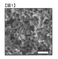
- FIG. 2 is a scanning electron micrograph of a porous carbon material in Example 1.
- the carbon material used for the electrode material of the present invention (hereinafter sometimes referred to as “the carbon material of the present invention” for the sake of convenience) has a co-continuous structure portion in which the carbon skeleton and the voids each form a continuous structure. That is, for example, when a surface of a sample that has been sufficiently cooled in liquid nitrogen is cleaved with tweezers or the like, when the surface is observed with a scanning electron microscope (SEM) or the like, the carbon skeleton and voids formed as portions other than the skeleton are formed. Specifically, as illustrated in the scanning electron micrograph of the carbon material of Example 1 in FIG. 1, a carbon skeleton and voids are observed as continuous structures in the depth direction. It has a part.
- SEM scanning electron microscope
- the carbon material of the present invention it is possible to exhibit the rapid movement characteristics of the electrolyte by filling and / or flowing the electrolyte in the voids of the co-continuous structure portion.
- the carbon skeleton is continuous, electrical conductivity and thermal conductivity are increased. Therefore, a material with low resistance and low loss can be provided as a battery material. It is also possible to quickly exchange heat with the outside of the system and maintain high temperature uniformity.
- the material can be made highly resistant to deformation such as tension and compression.
- co-continuous structures include lattices and monoliths. Although it does not specifically limit, it is preferable that it is monolithic in the point which can exhibit the said effect.
- the co-continuous structure as used in the present invention refers to a form in which the carbon skeleton forms a three-dimensional network structure, and is generated by removing aggregated and coupled template particles, or a structure in which individual particles are aggregated and coupled. A distinction is made between irregular structures such as those formed by voids and surrounding skeletons.
- the structural period of the co-continuous structure portion in the carbon material of the present invention is preferably 0.002 ⁇ m to 3 ⁇ m.
- the structural period refers to the following from the scattering angle ⁇ corresponding to the maximum value of the scattering intensity peak when X-rays having a wavelength ⁇ are incident on the carbon material sample of the present invention by the X-ray scattering method. It is calculated by a formula.
- the structural period exceeds 1 ⁇ m and the X-ray scattering intensity peak cannot be observed, the co-continuous structure portion of the porous carbon material is photographed three-dimensionally by the X-ray CT method, the spectrum is obtained by performing Fourier transform, Similarly, the structure period is calculated. That is, the spectrum referred to in the present invention is data indicating the relationship between the one-dimensional scattering angle and the scattering intensity obtained by the X-ray scattering method or obtained by Fourier transform from the X-ray CT method.
- the structural period is preferably 0.01 ⁇ m or more, and more preferably 0.1 ⁇ m or more. Moreover, a high surface area and physical property can be acquired as a structural period is 3 micrometers or less. The structural period is preferably 2 ⁇ m or less, and more preferably 1 ⁇ m or less.
- the structure period of the co-continuous structure forming portion is assumed to be the structure period calculated by the above formula.
- the co-continuous structure portion preferably has an average porosity of 10 to 80%.
- the average porosity is an enlargement ratio adjusted to be 1 ⁇ 0.1 (nm / pixel) of a cross section in which an embedded sample is precisely formed by a cross section polisher method (CP method).
- the image is calculated by the following expression from an image observed at a resolution of at least a pixel, where the area of interest required for calculation is set in 512 pixels square, the area of the area of interest is A, and the area of the hole is B.
- Average porosity (%) B / A ⁇ 100
- the average porosity of the co-continuous structure portion is preferably 15 to 75%, more preferably 18 to 70%.
- the carbon material of the present invention has pores having an average diameter of 0.01 to 10 nm on the surface.
- the surface refers to a contact surface with any outside of the porous carbon material including the surface of the carbon skeleton in the co-continuous structure portion of the carbon material.
- the pores can be formed on the surface of the carbon skeleton in the co-continuous structure portion and / or in the portion substantially not having the co-continuous structure described later. It is preferably formed on the surface of the carbon skeleton at least in the co-continuous structure portion.
- Sulfur described later is contained in voids and surface pores of the above-described co-continuous structure portion of the carbon material, and is preferably contained at least in the surface pores.
- sulfur in the pores on the surface, it is possible to expect effects such as a reduction in output due to outflow of sulfur, damage to the electrodes, or rapid movement of electrons.
- the presence of communicating voids enables rapid diffusion and migration of the electrolyte into the sulfur.
- the average diameter of such surface pores is preferably 0.1 nm or more, and more preferably 0.5 nm or more. Moreover, it is preferable that it is 5 nm or less, and it is more preferable that it is 2 nm or less.
- the pore volume of the carbon material of the present invention is preferably 0.5 cm 3 / g or more. It is more preferably 1.0 cm 3 / g or more, and further preferably 1.5 cm 3 / g or more.
- the pore volume is 0.5 cm 3 / g or more, a large amount of sulfur can be filled in the pores.
- an upper limit is not specifically limited, By making it 10 cm ⁇ 3 > / g or less, intensity
- the value measured by either BJH method or MP method is used for the average diameter and pore volume of the pores in the carbon material of the present invention. That is, if either one of the measured values by the BJH method or the MP method falls within the range of 0.01 to 10 nm, it is determined that the surface has pores having an average diameter of 0.01 to 10 nm.
- an appropriate method varies depending on the size of the diameter (for example, an appropriate method varies with a diameter of 2 nm as described later), in the present invention, the value obtained by any method may be within the range of the present invention. Shall.
- the BJH method and the MP method are widely used as pore size distribution analysis methods, and can be obtained based on a desorption isotherm obtained by adsorbing and desorbing nitrogen on an electrode material.
- the BJH method is a method of analyzing the pore volume distribution with respect to the pore diameter assumed to be cylindrical according to the Barrett-Joyner-Halenda standard model, and can be applied mainly to pores having a diameter of 2 to 200 nm. (For details, see J. Amer. Chem. Soc., 73, 373, 1951 etc.).
- the MP method is based on the external surface area and adsorption layer thickness (corresponding to the pore radius because the pore shape is cylindrical) obtained from the change in the tangential slope at each point of the adsorption isotherm. This is a method for obtaining the pore volume and plotting it against the thickness of the adsorbed layer to obtain the pore size distribution (for details, see Jounalof Colloid and Interface Science, 26, 45, 1968, etc.), mainly 0.4 to 2 nm Applicable to pores having a diameter.
- the voids in the co-continuous structure portion may affect the pore size distribution and pore volume measured by the BJH method or the MP method. That is, these measured values may be obtained as values that reflect not only the pores but also the presence of voids. Even in such a case, the measured values obtained by these methods are determined to be the pore diameter and pore volume in the present invention.
- the carbon material of the present invention preferably has a BET specific surface area of 300 m 2 / g or more.
- the BET specific surface area is more preferably 1000 m 2 / g or more, further preferably 1500 m 2 / g or more, and further preferably 2000 m 2 / g or more.
- the area with respect to electrolyte becomes large and performance improves.
- an upper limit is not specifically limited, In the range which does not exceed 4500 m ⁇ 2 > / g, the intensity
- the BET specific surface area in this invention can measure an adsorption isotherm by making nitrogen adsorption / desorption to a carbon material according to JISR 1626 (1996), and can calculate the measured data based on a BET formula.
- the numerical ranges of the structural period, specific surface area, pore volume, and porosity in the present invention are values in a state before containing sulfur, which will be described later.
- the electrode material of the present invention includes a portion that does not substantially have a co-continuous structure (hereinafter, simply referred to as “a portion that does not have a co-continuous structure”).
- the portion having substantially no co-continuous structure is a portion below the resolution when a cross section formed by the cross section polisher method (CP method) is observed at an enlargement ratio of 1 ⁇ 0.1 (nm / pixel). This means that a part where no clear air gap is observed exists in an area equal to or larger than a square region corresponding to three times the structural period L calculated from the X-ray described later.
- the part that does not substantially have a co-continuous structure is densely filled with carbon, so that the transfer of electrons is easy, and thus the electrical and thermal conductivity is high. Therefore, electrical conductivity and thermal conductivity can be maintained at a certain level or more, reaction heat can be quickly discharged out of the system, and resistance during electron transfer can be reduced.
- electrical conductivity and thermal conductivity can be maintained at a certain level or more, reaction heat can be quickly discharged out of the system, and resistance during electron transfer can be reduced.
- the shape of the carbon material of the present invention is not particularly limited, and examples thereof include a lump shape, a rod shape, a flat plate shape, a disc shape, and a spherical shape. Of these, a fibrous, film-like or particulate form is preferred. If it is a fiber and a film form, it is preferable at the point which can be set as the electrode which does not use a binder, On the other hand, if it is a particulate form, it is preferable at the point which is excellent in handleability.
- the fibrous form refers to one having an average length of 100 times or more with respect to the average diameter, and may be a filament, a long fiber, a staple, a short fiber, or a chopped fiber.
- the shape of the cross section is not limited at all, and can be an arbitrary shape such as a multi-leaf cross section such as a round cross section or a triangular cross section, a flat cross section or a hollow cross section.
- the average diameter of the fiber is not particularly limited and can be arbitrarily determined according to the application. From the viewpoint of maintaining handleability and porosity, the thickness is preferably 10 nm or more. Moreover, it is preferable that it is 500 micrometers or less from a viewpoint of ensuring bending rigidity and improving a handleability.
- the thickness is not particularly limited and can be arbitrarily determined according to the application. In consideration of handleability, it is preferably 10 nm or more, and preferably 5000 ⁇ m or less from the viewpoint of preventing breakage due to bending.
- the average particle size is in the range of 1 ⁇ m to 1 mm because it is easy to handle. By setting the thickness to 1 ⁇ m or more, a co-continuous structure can be easily formed.
- the average particle size is more preferably 2 ⁇ m or more, and further preferably 5 ⁇ m or more. Moreover, it can be set as a smooth and high-density electrode by setting it as 10 micrometers or less.
- the average particle size is more preferably 8 ⁇ m or less.
- sulfur means not only elemental sulfur but also sulfur compounds.
- sulfur compounds include, but are not limited to, disulfides, poly (disulfides), polysulfides, thiols, and modified products thereof.
- the electrode material of the present invention preferably contains sulfur in the voids in the co-continuous structure portion of the carbon material and the pores on the surface, and particularly preferably contains sulfur in at least the surface pores. Sulfur may completely fill the surface pores. It is preferable to leave the voids in the communicating co-continuous structure portion because the diffusion and migration of the electrolyte are improved. From this point of view, it is preferable that the ratio of sulfur to 1 to 97% by volume with respect to the voids determined by the porosity measurement method described later of the carbon material.
- the electrode of the present invention includes the electrode material of the present invention. Specifically, the electrode material of the present invention and, if necessary, a conductive material, a binder, and the like are mixed, and an active material is formed on the current collector. It is formed as a layer.
- the electrode is particularly preferably a positive electrode of a lithium sulfur battery.
- the conductive material is not particularly limited.
- graphite such as natural graphite or artificial graphite, acetylene black, carbon black, ketjen black, carbon whisker, needle coke, carbon fiber, metal (copper, nickel, aluminum, silver, What mixed 1 type, such as gold
- carbon black, ketjen black, and acetylene black are preferable as the conductive material from the viewpoints of electron conductivity and coatability.
- binder examples include rubber binders such as styrene-butadiene rubber (SBR) and acrylonitrile-butadiene rubber (NBR); fluorine resins such as polytetrafluoroethylene and polyvinylidene fluoride; polypropylene, polyethylene, fluorine-modified ( And a (meth) acrylic binder.
- SBR styrene-butadiene rubber
- NBR acrylonitrile-butadiene rubber
- fluorine resins such as polytetrafluoroethylene and polyvinylidene fluoride
- polypropylene polyethylene
- fluorine-modified ( And a (meth) acrylic binder examples of the binder.
- the amount of the binder used is not particularly limited, but is preferably 1 to 20% by mass, more preferably 2 to 10% by mass.
- the active material layer constituting the electrode may contain a thickening agent such as carboxymethyl cellulose or a salt thereof, methyl cellulose, hydroxymethyl cellulose, ethyl cellulose, hydroxypropyl cellulose, or polyvinyl alcohol.
- a thickening agent such as carboxymethyl cellulose or a salt thereof, methyl cellulose, hydroxymethyl cellulose, ethyl cellulose, hydroxypropyl cellulose, or polyvinyl alcohol.
- the thickness of the active material layer is not particularly limited, but is usually 5 to 500 ⁇ m, preferably 10 to 200 ⁇ m, particularly preferably 10 to 100 ⁇ m.
- the lithium-sulfur battery of the present invention is a positive electrode including the electrode material of the present invention described above, and a negative electrode formed of a material that absorbs and releases lithium. Although it does not specifically limit about another member, An example is shown below.
- a material in which a negative electrode active material, a conductive material, and a binder are coated on the surface of a current collector is generally used.
- the negative electrode active material a material that absorbs and releases lithium is used, and a material containing a metal or a metal ion is preferably used.
- the material that absorbs and releases lithium include metal lithium, lithium alloy, metal oxide, metal sulfide, and a carbonaceous material that absorbs and releases lithium.
- the lithium alloy include an alloy of lithium and aluminum, silicon, tin, magnesium, indium, calcium, or the like.
- the metal oxide include tin oxide, silicon oxide, lithium titanium oxide, niobium oxide, and tungsten oxide.
- Examples of the metal sulfide include tin sulfide and titanium sulfide.
- Examples of the carbonaceous substance that absorbs and releases lithium include graphite, coke, mesophase pitch carbon fiber, spherical carbon, and resin-fired carbon.
- an organic or inorganic porous sheet is generally used as the separator.
- the electrolytic solution when the electrolytic solution is interposed at least between the positive electrode and the separator, polysulfide ions, sulfide ions, and sulfur molecules generated at the positive electrode are dissolved in the electrolytic solution, and the efficiency of supplying the active material is further improved. It is preferable for reasons such as being good. It is not always necessary that the electrolyte be present between the negative electrode and the separator. However, when the contact state between solids is not good, etc., there is an effect that the ion conduction can be made good by the electrolytic solution, so that the electrolytic solution is interposed between the negative electrode and the separator. Is preferred.
- the electrolytic solution may be a solution in which a lithium salt is dissolved in a solvent.
- the lithium salt is not particularly limited as long as it is used for an ordinary lithium ion secondary battery.
- Li (CF 3 SO 2 ) 2 N, Li (C 2 F 5 SO 2 ) 2 N , LiPF 6 , LiClO 4 , LiBF 4 , and the like can be used. These may be used alone or in combination.
- the solvent of the electrolytic solution is not particularly limited as long as it is a non-proton-donating and used in a normal lithium ion secondary battery.
- ethers such as dimethoxyethane (DME), triglyme, and tetraglyme, dioxolane (DOL) ), Cyclic ethers such as tetrahydrofuran, and mixtures thereof are preferably used.
- ionic liquids such as 1-methyl-3-propylimidazolium bis (trifluorosulfonyl) imide and 1-ethyl-3-butylimidazolium tetrafluoroborate can be used.
- the electrolytic solution only needs to be interposed at least between the positive electrode and the separator, and a supporting salt is attached to a polymer such as polyvinylidene fluoride, polyethylene oxide, polyethylene glycol, polyacrylonitrile, or a saccharide such as an amino acid derivative or a sorbitol derivative. It may be gelled by containing an electrolyte solution. Also, in sulfur batteries, the amount of active material that can be effectively used may decrease due to the dissolution of the active material (sulfur, polysulfide ions, etc.) in the solution, so polysulfide ions, etc. are added to the electrolyte beforehand. You may keep it.
- the shape of the lithium-sulfur battery of the present invention is not particularly limited, and examples thereof include a coin type, a button type, a sheet type, a laminated type, a cylindrical type, a flat type, and a square type.
- the electrode material of the present invention includes, as an example, a step (Step 1) in which 10 to 90% by weight of carbonizable resin and 90 to 10% by weight of disappearing resin are mixed to form a resin mixture, and a resin mixture in a compatible state Phase separation and immobilization (step 2), carbonization by heating and firing (step 3), and sulfur incorporation step (step 4). Moreover, the process 4 can be performed after passing the process of activating a carbide
- Step 1 is a step in which 10 to 90% by weight of the carbonizable resin and 90 to 10% by weight of the disappearing resin are mixed to form a resin mixture.
- the carbonizable resin is a resin that is carbonized by firing and remains as a carbon material, and preferably has a carbonization yield of 40% or more.
- a thermoplastic resin and a thermosetting resin can be used.
- the thermoplastic resin include polyphenylene oxide, polyvinyl alcohol, polyacrylonitrile, phenol resin, and wholly aromatic polyester.
- thermosetting resins include unsaturated polyester resins, alkyd resins, melamine resins, urea resins, polyimide resins, diallyl phthalate resins, lignin resins, urethane resins, and the like. In view of cost and productivity, polyacrylonitrile and phenol resin are preferable, and polyacrylonitrile is more preferable.
- polyacrylonitrile is a preferred embodiment because a high specific surface area can be obtained. These may be used alone or in a mixed state.
- the carbonization yield here is the difference between the weight at room temperature and the weight at 800 ° C. by measuring the change in weight when the temperature is raised at 10 ° C./min in a nitrogen atmosphere by the thermogravimetry (TG) method. Is divided by the weight at room temperature.
- the disappearing resin is a resin that can be removed after Step 2 described later, and is preferably a resin that can be removed at least in any stage of the infusibilization treatment, the infusibilization treatment, or the firing. .
- the removal rate is preferably 80% by weight or more, more preferably 90% by weight or more when finally becoming a carbon material.
- the method for removing the disappearing resin is not particularly limited, and is a method of chemically removing the polymer by depolymerizing it with a chemical, a method of removing the disappearing resin with a solvent that dissolves, or by thermal decomposition by heating. A method of removing the lost resin by reducing the molecular weight is preferably used. These methods can be used singly or in combination, and when implemented in combination, each may be performed simultaneously or separately.
- a method of hydrolyzing with an acid or alkali is preferable from the viewpoints of economy and handleability.
- the resin that is susceptible to hydrolysis by acid or alkali include polyester, polycarbonate, and polyamide.
- the mixed carbonizable resin and the disappearing resin are continuously supplied with a solvent to dissolve and remove the disappearing resin, or mixed in a batch system.
- a suitable example is a method of dissolving and removing the disappearing resin.
- the disappearing resin suitable for the removal method using a solvent include polyolefins such as polyethylene, polypropylene, and polystyrene, acrylic resins, methacrylic resins, polyvinylpyrrolidone, aliphatic polyesters, and polycarbonates.
- polyolefins such as polyethylene, polypropylene, and polystyrene
- acrylic resins methacrylic resins
- polyvinylpyrrolidone aliphatic polyesters
- polycarbonates examples include polystyrene, methacrylic resin, polycarbonate, and polyvinylpyrrolidone.
- a method of removing the lost resin by reducing the molecular weight by thermal decomposition a method in which the mixed carbonizable resin and the lost resin are heated in a batch manner to thermally decompose, or a continuously mixed carbonized resin and the lost resin are removed.
- a method of heating and thermally decomposing while continuously supplying to a heat source a method in which the mixed carbonizable resin and the lost resin are heated in a batch manner to thermally decompose, or a continuously mixed carbonized resin and the lost resin are removed.
- the disappearing resin is preferably a resin that disappears due to thermal decomposition when carbonizing the carbonizable resin by firing in Step 3 described later. Moreover, it is preferable that it is resin which does not raise
- Specific examples of such disappearing resins include polyolefins such as polyethylene, polypropylene and polystyrene, acrylic resins, methacrylic resins, polyacetals, polyvinylpyrrolidones, aliphatic polyesters, aromatic polyesters, aliphatic polyamides, polycarbonates and the like. These may be used alone or in a mixed state.
- step 1 the carbonizable resin and the disappearing resin are mixed to form a resin mixture (polymer alloy).
- “Compatibilized” as used herein refers to creating a state in which the phase separation structure of the carbonizable resin and the disappearing resin is not observed with an optical microscope by appropriately selecting the temperature and / or solvent conditions.
- the carbonizable resin and the disappearing resin may be compatible by mixing only the resins, or may be compatible by adding a solvent or the like.
- a system in which a plurality of resins are compatible includes a phase diagram of an upper critical eutectic temperature (UCST) type that is in a phase separation state at a low temperature but has one phase at a high temperature, and conversely, a phase separation state at a high temperature.
- UCT upper critical eutectic temperature
- LCST lower critical solution temperature
- the solvent to be added is not particularly limited. It is preferable that the absolute value of the difference from the average value of the solubility parameter (SP value) of the carbonizable resin and the disappearing resin, which serves as a solubility index, is within 5.0. Since it is known that the smaller the absolute value of the difference from the average value of SP values, the higher the solubility, it is preferable that there is no difference. Further, the larger the absolute value of the difference from the average SP value, the lower the solubility, and it becomes difficult to take a compatible state between the carbonizable resin and the disappearing resin. Therefore, the absolute value of the difference from the average value of SP values is preferably 3.0 or less, and most preferably 2.0 or less.
- carbonizable resins and disappearing resins are polyphenylene oxide / polystyrene, polyphenylene oxide / styrene-acrylonitrile copolymer, wholly aromatic polyester / polyethylene as long as they do not contain solvents.
- examples include terephthalate, wholly aromatic polyester / polyethylene naphthalate, wholly aromatic polyester / polycarbonate.
- combinations of systems containing solvents include polyacrylonitrile / polyvinyl alcohol, polyacrylonitrile / polyvinylphenol, polyacrylonitrile / polyvinylpyrrolidone, polyacrylonitrile / polylactic acid, polyvinyl alcohol / vinyl acetate-vinyl alcohol copolymer, polyvinyl Examples include alcohol / polyethylene glycol, polyvinyl alcohol / polypropylene glycol, and polyvinyl alcohol / starch.
- the method of mixing the carbonizable resin and the disappearing resin is not limited, and various known mixing methods can be adopted as long as uniform mixing is possible. Specific examples include a rotary mixer having a stirring blade and a kneading extruder using a screw.
- the temperature (mixing temperature) when mixing the carbonizable resin and the disappearing resin is equal to or higher than the temperature at which both the carbonizable resin and the disappearing resin are softened.
- the softening temperature may be appropriately selected as the melting point if the carbonizable resin or disappearing resin is a crystalline polymer, and the glass transition temperature if it is an amorphous resin.
- the upper limit of the mixing temperature is not particularly limited. From the viewpoint of preventing the deterioration of the resin due to thermal decomposition and obtaining a precursor of a carbon material excellent in quality, the temperature is preferably 400 ° C. or lower.
- Step 1 90 to 10% by weight of the disappearing resin is mixed with 10 to 90% by weight of the carbonizable resin. It is preferable that the carbonizable resin and the disappearing resin are within the above-mentioned range since an optimum void size and void ratio can be arbitrarily designed. If the carbonizable resin is 10% by weight or more, it is possible to maintain the mechanical strength of the carbonized material and improve the yield. Further, if the carbonizable material is 90% by weight or less, it is preferable because the lost resin can efficiently form voids.
- the mixing ratio of the carbonizable resin and the disappearing resin can be arbitrarily selected within the above range in consideration of the compatibility of each material. Specifically, in general, the compatibility between resins deteriorates as the composition ratio approaches 1: 1, so when a system that is not very compatible is selected as a raw material, the amount of carbonizable resin is increased. It is also preferable to improve the compatibility by reducing it so that it approaches a so-called uneven composition.
- a solvent when mixing the carbonizable resin and the disappearing resin. Addition of a solvent lowers the viscosity of the carbonizable resin and the disappearing resin to facilitate molding, and facilitates compatibilization of the carbonizable resin and the disappearing resin.
- the solvent here is not particularly limited as long as it is a liquid at room temperature that can dissolve and swell at least one of carbonizable resin and disappearing resin. Any resin that dissolves the resin is more preferable because the compatibility between the two can be improved.
- the addition amount of the solvent should be 20% by weight or more based on the total weight of the carbonizable resin and the disappearing resin from the viewpoint of improving the compatibility between the carbonizable resin and the disappearing resin and reducing the viscosity to improve the fluidity. preferable. On the other hand, from the viewpoint of costs associated with recovery and reuse of the solvent, it is preferably 90% by weight or less based on the total weight of the carbonizable resin and the disappearing resin.
- Step 2 is a step of forming a fine structure by immobilizing the resin mixture in the state of compatibility in Step 1 by a method not involving a chemical reaction, and immobilizing.
- Phase separation of mixed carbonizable resin and disappearing resin can be induced by various physical and chemical methods, for example, by thermally induced phase separation method that induces phase separation by temperature change, by adding non-solvent Non-solvent induced phase separation to induce phase separation, flow induced phase separation to induce phase separation by physical field, orientation induced phase separation, electric field induced phase separation, magnetic field induced phase separation, pressure induced phase separation
- thermally induced phase separation method that induces phase separation by temperature change
- Non-solvent induced phase separation to induce phase separation
- flow induced phase separation to induce phase separation by physical field
- orientation induced phase separation to induce phase separation by physical field
- orientation induced phase separation electric field induced phase separation
- magnetic field induced phase separation magnetic field induced phase separation
- pressure induced phase separation There are various methods such as a reaction-induced phase separation method that induces phase separation using a chemical reaction or a chemical reaction. In the production method of the present invention, reaction-induced phase separation is excluded for the reasons described later.
- phase separation methods can be used alone or in combination.
- Specific methods for use in combination include, for example, a method in which non-solvent induced phase separation is caused through a coagulation bath and then heated to cause heat-induced phase separation, or a temperature in the coagulation bath is controlled to control a non-solvent induced phase.
- Examples thereof include a method of causing separation and thermally induced phase separation at the same time, a method of bringing the material discharged from the die into cooling and causing thermally induced phase separation, and then contacting with a non-solvent.
- the primary structure refers to a chemical structure that constitutes a carbonizable resin or a disappearing resin.
- the resin mixture in which the microstructure after phase separation is fixed in Step 2 is subjected to the removal treatment of the lost resin before being subjected to the carbonization step (Step 3), simultaneously with the carbonization step, or both.
- the method for the removal treatment is not particularly limited as long as the disappearing resin can be removed. Specifically, the method of removing the lost resin by chemically decomposing and reducing the molecular weight using acid, alkali or enzyme, the method of removing by dissolving with a solvent that dissolves the lost resin, electron beam, gamma ray, ultraviolet ray, infrared ray A method of decomposing and removing the disappearing resin using radiation or heat such as is suitable.
- a heat treatment can be performed at a temperature at which 80% by weight or more of the disappearance resin disappears in advance, and a carbonization step (step 3) or infusibilization described later.
- the lost resin can be removed by pyrolysis and gasification. From the viewpoint of increasing the productivity by reducing the number of steps, it is more preferable to select a method in which the lost resin is thermally decomposed and gasified and removed simultaneously with the heat treatment in the carbonization step (step 3) or infusibilization treatment described later. It is.
- the precursor material which is a resin mixture in which the microstructure after phase separation is fixed in step 2, is preferably subjected to an infusibilization treatment before being subjected to the carbonization step (step 3).
- the infusible treatment method is not particularly limited, and a known method can be used. Specific methods include a method of causing oxidative crosslinking by heating in the presence of oxygen, a method of forming a crosslinked structure by irradiating high energy rays such as electron beams and gamma rays, and impregnating a substance having a reactive group, Examples thereof include a method of mixing to form a crosslinked structure. Among them, the method of causing oxidative crosslinking by heating in the presence of oxygen is preferable because the process is simple and the production cost can be kept low. These methods may be used singly or in combination, and each may be used simultaneously or separately.
- the heating temperature in the method of causing oxidative crosslinking by heating in the presence of oxygen is preferably 150 ° C. or higher from the viewpoint of efficiently proceeding with the crosslinking reaction, and it can be recovered from weight loss due to thermal decomposition, combustion, etc. of carbonizable resin. From the viewpoint of preventing rate deterioration, the temperature is preferably 350 ° C. or lower.
- the oxygen concentration during the treatment is not particularly limited, but it is preferable to supply a gas having an oxygen concentration of 18% or more, particularly air, as it is because manufacturing costs can be kept low.
- the method for supplying the gas is not particularly limited, and examples thereof include a method for supplying air directly into the heating device and a method for supplying pure oxygen into the heating device using a cylinder or the like.
- the carbonizable resin is irradiated with an electron beam or gamma ray using a commercially available electron beam generator or gamma ray generator. And a method of inducing cross-linking.
- the lower limit of the irradiation intensity is preferably 1 kGy or more from the efficient introduction of a crosslinked structure by irradiation, and is preferably 1000 kGy or less from the viewpoint of preventing the material strength from being lowered due to the decrease in molecular weight due to cleavage of the main chain.
- a method of forming a crosslinked structure by impregnating and mixing a substance having a reactive group is a method in which a low molecular weight compound having a reactive group is impregnated in a resin mixture, and a crosslinking reaction is advanced by irradiation with heat or high energy rays. And a method in which a low molecular weight compound having a reactive group is mixed in advance and the crosslinking reaction is advanced by heating or irradiation with high energy rays.
- Step 3 is a step in which the resin mixture in which the microstructure after phase separation is fixed in Step 2 or the carbonizable resin is baked and carbonized to obtain a carbide when the disappearing resin has already been removed.
- Calcination is preferably performed by heating to 600 ° C. or higher in an inert gas atmosphere.
- the inert gas means a gas that is chemically inert when heated.
- Specific examples include helium, neon, nitrogen, argon, krypton, xenon, carbon dioxide and the like. Of these, nitrogen and argon are preferably used from the economical viewpoint.
- nitrogen and argon are preferably used from the economical viewpoint.
- the carbonization temperature is 1500 ° C. or higher, argon is preferably used from the viewpoint of suppressing nitride formation.
- the flow rate of the inert gas may be an amount that can sufficiently reduce the oxygen concentration in the heating device, and an optimal value can be selected as appropriate depending on the size of the heating device, the amount of raw material supplied, the heating temperature, and the like. preferable.
- the upper limit of the flow rate is not particularly limited, but is preferably set appropriately in accordance with the temperature distribution and the design of the heating device, from the viewpoint of economy and the temperature change in the heating device being reduced. Further, if the gas generated during carbonization can be sufficiently discharged out of the system, a carbon material with excellent quality can be obtained, which is a more preferable embodiment. Therefore, it is preferable to determine the flow rate of the inert gas so that the generated gas concentration in the system is 3,000 ppm or less.
- the upper limit of the heating temperature is not limited, but if it is 3000 ° C. or lower, no special processing is required for the equipment, which is preferable from an economical viewpoint. Moreover, in order to raise a BET specific surface area, it is preferable that it is 1500 degrees C or less, and it is more preferable that it is 1000 degrees C or less.
- the heating method in the case of continuously performing carbonization treatment, it is a method to take out the material while continuously supplying the material using a roller, a conveyor, or the like in a heating device maintained at a constant temperature. It is preferable because it can be increased.
- the rate is preferably 1 ° C./min or more.
- the upper limit of the temperature increase rate and the temperature decrease rate is not particularly limited, it is preferable to make it slower than the thermal shock resistance of the material constituting the heating device.
- the carbide obtained in step 3 is preferably activated as necessary.
- the activation treatment method is not particularly limited, such as a gas activation method or a chemical activation method.
- the gas activation method is a method of forming pores by heating at 400 to 1500 ° C., preferably 500 to 900 ° C. for several minutes to several hours, using oxygen, water vapor, carbon dioxide gas, air or the like as an activator. It is.
- the chemical activation method is one or two kinds of activator such as zinc chloride, iron chloride, calcium phosphate, calcium hydroxide, potassium hydroxide, magnesium carbonate, sodium carbonate, potassium carbonate, sulfuric acid, sodium sulfate, potassium sulfate, etc.
- activator such as zinc chloride, iron chloride, calcium phosphate, calcium hydroxide, potassium hydroxide, magnesium carbonate, sodium carbonate, potassium carbonate, sulfuric acid, sodium sulfate, potassium sulfate, etc.
- the BET specific surface area increases and the pore diameter tends to increase by further increasing the activation or increasing the amount of the activator mixed.
- the mixing amount of the activator is preferably 0.5 parts by weight or more, more preferably 1.0 parts by weight or more, and further preferably 4 parts by weight or more with respect to 1 part by weight of the target carbon raw material. Although an upper limit is not specifically limited, 10 weight part or less is common.
- the pore diameter tends to be larger in the chemical activation method than in the gas activation method.
- the chemical activation method is preferably employed because the pore diameter can be increased or the BET specific surface area can be increased.
- a method of activating with an alkaline agent such as calcium hydroxide, potassium hydroxide, potassium carbonate is preferably employed.
- the electrode material of the present invention is pulverized into particles after any of the above steps.
- a conventionally known method can be selected for the pulverization treatment, and it is preferable that the pulverization treatment is appropriately selected according to the particle size and the processing amount after the pulverization treatment.
- Examples of the pulverization method include a ball mill, a bead mill, and a jet mill.
- the pulverization process may be a continuous type or a batch type. It is preferable that it is a continuous type from a viewpoint of production efficiency.
- the filler for filling the ball mill is appropriately selected.
- metal oxides such as alumina, zirconia, and titania, or those coated with nylon, polyolefin, fluorinated polyolefin, etc. with stainless steel, iron, etc. as the core.
- metals such as stainless steel, nickel, and iron are preferably used.
- the grinding aid is arbitrarily selected from water, alcohol or glycol, ketone and the like.
- the alcohol ethanol and methanol are preferable from the viewpoint of availability and cost, and in the case of glycol, ethylene glycol, diethylene glycol, propylene glycol and the like are preferable.
- a ketone acetone, ethyl methyl ketone, diethyl ketone and the like are preferable.
- the pulverized carbide has a uniform particle size by classification, and a uniform structure can be formed by, for example, a filler or an additive to the paste. For this reason, it becomes possible to stabilize the filling efficiency and the paste coating process, and it can be expected to increase the production efficiency and reduce the cost.
- a particle size it is preferable to select suitably according to the use of the carbide
- Step 4 is a step of incorporating sulfur into the pores and voids of the carbon material obtained as described above.
- sulfur those described above can be used.
- the method for causing sulfur to be contained in the pores and voids of the carbon material is not particularly limited, and examples thereof include a method of filling sulfur after making it into a gas or liquid.
- sulfur after sulfur is heated and / or pressurized to be gasified, it can be adsorbed and filled using the adsorption ability of porous carbon.
- sulfur can be heated and melted, and filled using porous carbon adsorption ability, osmotic pressure, and the like.
- it can be filled by a method of filling as a sulfur solution with a solvent, a vapor phase growth method, or the like.
- X-ray scattering method Position the light source, sample, and two-dimensional detector so that information with a scattering angle of less than 10 degrees can be obtained from an X-ray source obtained from a CuK ⁇ ray light source by sandwiching a carbon material between sample plates. It was adjusted. From the image data (luminance information) obtained from the two-dimensional detector, the central portion affected by the beam stopper is excluded, a moving radius is provided from the beam center, and a luminance value of 360 ° is obtained for each angle of 1 °. The scattering intensity distribution curve was obtained by summing up. From the scattering angle ⁇ corresponding to the maximum value of the peak in the obtained curve, the structural period L of the co-continuous structure portion was obtained by the following equation.
- L ⁇ / (2sin ⁇ ) Structure period: L, ⁇ : wavelength of incident X-ray, ⁇ : scattering angle corresponding to the maximum value of scattering intensity peak [average porosity]
- a carbon material is embedded in a resin, and then a razor or the like is used to expose the cross-section of the electrode material, and the sample surface is irradiated with an argon ion beam at an acceleration voltage of 5.5 kV using JEOL SM-09010. Etching was performed.
- Average porosity (%) B / A ⁇ 100 [BET specific surface area, pore diameter]
- nitrogen adsorption / desorption at a temperature of 77K was measured by a multipoint method using “BELSORP-18PLUS-HT” manufactured by Bell Japan Ltd. using liquid nitrogen.
- the specific surface area was determined by the BET method, and the pore distribution analysis (pore diameter, pore volume) was performed by the MP method or BJH method.
- Example 1 70 g of polyacrylonitrile (MW 150,000, carbon yield 58%), 70 g of polyvinyl pyrrolidone (MW 40,000) manufactured by Sigma-Aldrich, and 400 g of dimethyl sulfoxide (DMSO) manufactured by Waken Pharmaceutical as a solvent are separated. A uniform and transparent solution was prepared at 150 ° C. while stirring and refluxing for 3 hours. At this time, the concentration of polyacrylonitrile and the concentration of polyvinylpyrrolidone were 13% by weight, respectively.
- DMSO dimethyl sulfoxide
- the solution After cooling the obtained DMSO solution to 25 ° C., the solution is discharged at a rate of 3 ml / min from a 0.6 mm ⁇ 1-hole cap and led to a pure water coagulation bath maintained at 25 ° C., and then 5 m / min.
- the yarn was taken up at a speed and deposited on the bat to obtain a raw yarn. At this time, the air gap was 5 mm, and the immersion length in the coagulation bath was 15 cm.
- the obtained raw yarn was translucent and caused phase separation.
- the obtained yarn is dried for 1 hour in a circulation drier kept at 25 ° C. to dry the moisture on the surface of the yarn, followed by vacuum drying at 25 ° C. for 5 hours.
- Raw material yarn was obtained.
- the raw yarn as a precursor material was put into an electric furnace maintained at 250 ° C. and infusibilized by heating in an oxygen atmosphere for 1 hour.
- the raw yarn that had been infusibilized changed to black.
- Carbon fiber having a co-continuous structure is obtained by carbonizing the obtained infusible raw material under the conditions of a nitrogen flow rate of 1 liter / min, a heating rate of 10 ° C./min, an ultimate temperature of 850 ° C., and a holding time of 1 min. did.
- the cross section was analyzed, the fiber diameter was 155 ⁇ m, and the thickness of the portion having no co-continuous structure formed on the fiber surface was 5 ⁇ m.
- a uniform co-continuous structure was formed at the center of the fiber.
- potassium hydroxide was mixed with an amount 4 times that of carbide, charged into a rotary kiln, and heated to 800 ° C. under a nitrogen flow. After the activation treatment for 1 hour and 30 minutes, the temperature was lowered, and then washing was performed using water and dilute hydrochloric acid until the washing solution reached pH7.
- the average porosity of the co-continuous structure portion was 40%, and the structural period was 79 nm. Moreover, it had the structure which included the part which does not have a co-continuous structure in some particle
- the BET specific surface area was 2080 m 2 / g, the average pore diameter by the MP method was 0.6 nm, and the pore volume was 2.0 cm 3 / g.
- Example 2 Using this DMF mixed solution, spinning, infusibilization, and carbonization were performed in the same manner as in Example 1 to obtain carbon fibers.
- the obtained carbon fiber was not uniform in pore shape and size in the cross section. Further, calculation of the structure period was attempted, but the obtained spectrum had no peak and was inferior in the uniformity of the structure. Subsequently, after pulverizing using a ball mill, carbon particles were obtained without performing activation treatment.
Landscapes
- Chemical & Material Sciences (AREA)
- General Chemical & Material Sciences (AREA)
- Chemical Kinetics & Catalysis (AREA)
- Electrochemistry (AREA)
- Engineering & Computer Science (AREA)
- Manufacturing & Machinery (AREA)
- Inorganic Chemistry (AREA)
- Materials Engineering (AREA)
- Composite Materials (AREA)
- Carbon And Carbon Compounds (AREA)
- Battery Electrode And Active Subsutance (AREA)
Abstract
Description
〔炭素材料〕
本発明の電極材料に用いる炭素材料(以下、便宜上「本発明の炭素材料」ということがある。)は、炭素骨格と空隙とがそれぞれ連続構造をなす共連続構造部分を有する。すなわち、例えば液体窒素中で充分に冷却した試料をピンセット等により割断した断面を走査型電子顕微鏡(SEM)などによって表面観察した際に、炭素骨格とその骨格以外の部分として形成された空隙とがいわゆる共連続構造となっており、具体的には図1の実施例1の炭素材料の走査型電子顕微鏡写真に例示される通り、奥行き方向に炭素骨格と空隙とがそれぞれ連続した構造として観察される部分を有する。
構造周期:L、λ:入射X線の波長、θ:散乱強度ピークの極大値に対応する散乱角度
共連続構造部分の構造周期が0.002μm以上であると、空隙部に電解液を充填及び/又は流すことができるほか、炭素骨格を通じて電気伝導性、熱伝導性を向上することが可能となる。構造周期は0.01μm以上であることが好ましく、0.1μm以上であることがより好ましい。また、構造周期が3μm以下であると、高い表面積や物性を得ることができる。構造周期は2μm以下であることが好ましく、1μm以下であることがより好ましい。なお、X線による構造周期の解析に際して、共連続構造を有しない部分については、構造周期が上記範囲外となるため解析には影響ない。よって、上記式で算出される構造周期を以って、共連続構造形成部の構造周期とするものとする。
平均空隙率は、高いほど電解質の移動が速やかになるほか、低いほど圧縮や曲げといった断面方向にかかる力に強くなるため、取り扱い性や加圧条件での使用に際して有利となる。これらのことを考慮し、共連続構造部分の平均空隙率は15~75%であることが好ましく、18~70%がさらに好ましい。
本発明において硫黄とは、元素状硫黄だけでなく、硫黄化合物をも含む意味である。硫黄化合物としては、例えば、ジスルフィド、ポリ(ジスルフィド)、ポリスルフィド、チオール及びこれらの変性物などが挙げられるが、これらに限定されるものではない。
本発明の電極は、本発明の電極材料を含むものであって、具体的には本発明の電極材料と、必要に応じて導電材、バインダー、等を混合して集電体上に活物質層として形成させたものである。電極は、特にリチウム硫黄電池の正極とすることが好ましい。
本発明のリチウム硫黄電池は、前述した本発明の電極材料を含む正極とし、リチウムを吸放出する材料で形成された負極とするものである。他の部材については、特に限定されないが、一例を以下に示す。
本発明の電極材料は、一例として、炭化可能樹脂10~90重量%と消失樹脂90~10重量%とを相溶させて樹脂混合物とする工程(工程1)と、相溶した状態の樹脂混合物を相分離させ、固定化する工程(工程2)、加熱焼成により炭化する工程(工程3)、硫黄を含有せしめる工程(工程4)により製造することができる。また、工程4は、必要に応じて炭化物を賦活する工程を経た後でことができる。
工程1は、炭化可能樹脂10~90重量%と、消失樹脂90~10重量%と相溶させ、樹脂混合物とする工程である。
工程2は、工程1において相溶させた状態の樹脂混合物を、化学反応を伴わない方法で相分離させて微細構造を形成し、固定化する工程である。
工程2において相分離後の微細構造が固定化された樹脂混合物は、炭化工程(工程3)に供される前または炭化工程と同時、あるいはその両方で消失樹脂の除去処理を行うことが好ましい。除去処理の方法は特に限定されるものではなく、消失樹脂を除去することが可能であれば良い。具体的には、酸、アルカリや酵素を用いて消失樹脂を化学的に分解、低分子量化して除去する方法や、消失樹脂を溶解する溶媒により溶解除去する方法、電子線、ガンマ線や紫外線、赤外線などの放射線や熱を用いて消失樹脂を分解除去する方法などが好適である。
工程2において相分離後の微細構造が固定化された樹脂混合物である前駆体材料は、炭化工程(工程3)に供される前に不融化処理を行うことが好ましい。不融化処理の方法は特に限定されるものではなく、公知の方法を用いることができる。具体的な方法としては、酸素存在下で加熱することで酸化架橋を起こす方法、電子線、ガンマ線などの高エネルギー線を照射して架橋構造を形成する方法、反応性基を持つ物質を含浸、混合して架橋構造を形成する方法などが挙げられる。中でも酸素存在下で加熱することで酸化架橋を起こす方法が、プロセスが簡便であり製造コストを低く抑えることが可能である点から好ましい。これらの手法は単独もしくは組み合わせて使用しても、それぞれを同時に使用しても別々に使用しても良い。
工程3は、工程2において相分離後の微細構造が固定化された樹脂混合物、あるいは、消失樹脂を既に除去している場合には炭化可能樹脂を焼成し、炭化して炭化物を得る工程である。
工程3において得た炭化物は、必要に応じて賦活することが好ましい。本発明において、特に比表面積を増加させる必要がある場合は、賦活処理を行うことが好ましい。賦活処理の方法としては、ガス賦活法、薬品賦活法等、特に限定するものではない。ガス賦活法とは、賦活剤として酸素や水蒸気、炭酸ガス、空気等を用い、400~1500℃、好ましくは500~900℃にて、数分から数時間、加熱することにより細孔を形成させる方法である。また、薬品賦活法とは、賦活剤として塩化亜鉛、塩化鉄、リン酸カルシウム、水酸化カルシウム、水酸化カリウム、炭酸マグネシウム、炭酸ナトリウム、炭酸カリウム、硫酸、硫酸ナトリウム、硫酸カリウム等を1種または2種以上用いて数分から数時間、加熱処理する方法であり、必要に応じて水や塩酸等による洗浄を行った後、pHを調整して乾燥する。
本発明の電極材料は、上記のいずれかの工程の後に、粉砕処理して粒子状とすることも好ましい態様である。粉砕処理は、従来公知の方法を選択することが可能であり、粉砕処理を施した後の粒度、処理量に応じて適宜選択されることが好ましい。粉砕処理方法の例としては、ボールミル、ビーズミル、ジェットミルなどを例示することができる。粉砕処理は、連続式でもバッチ式でも良い。生産効率の観点から連続式であることが好ましい。ボールミルに充填する充填材は適宜選択される。金属材料の混入が好ましくない用途に対しては、アルミナ、ジルコニア、チタニアなどの金属酸化物によるもの、もしくはステンレス、鉄などを芯としてナイロン、ポリオレフィン、フッ化ポリオレフィンなどをコーティングしたものを用いることが好ましく、それ以外の用途であればステンレス、ニッケル、鉄などの金属が好適に用いられる。
工程4は、上記のようにして得た炭素材料の細孔や空隙に硫黄を含有せしめる工程である。硫黄としては、前述のものを用いることができる。炭素材料の細孔や空隙へ硫黄を含有せしめる方法は、特に限定されないが、例えば、硫黄を気体または液体としてから充填する方法が挙げられる。例えば硫黄を加熱及び/又は加圧して気体化した後、多孔性炭素による吸着能を利用して吸着充填させることができる。また、硫黄を加熱して溶融させ、多孔性炭素の吸着能や浸透圧等を利用して充填させることもできる。充填量を高めるために、減圧と加圧を繰り返す等の操作をすることもできる。また、溶媒により硫黄溶液として充填する方法や、気相成長法等によっても充填することができる。
〔共連続構造部分の構造周期〕
(1)X線散乱法
炭素材料を試料プレートに挟み込み、CuKα線光源から得られたX線源から散乱角度10度未満の情報が得られるように、光源、試料及び二次元検出器の位置を調整した。二次元検出器から得られた画像データ(輝度情報)から、ビームストッパーの影響を受けている中心部分を除外して、ビーム中心から動径を設け、角度1°毎に360°の輝度値を合算して散乱強度分布曲線を得た。得られた曲線においてピークの極大値に対応する散乱角度θより、共連続構造部分の構造周期Lを下記の式によって得た。
また、構造周期が1μm以上であり、X線散乱強度ピークが観測されない場合には、X線顕微鏡で0.3°ステップ、180°以上で連続回転像を撮影し、CT像を得た。得られたCT像に対してフーリエ変換を実施し、散乱角度θと散乱強度のグラフ散乱強度分布曲線を得て、前述と同様の方法で下記式により構造周期Lを得た。
構造周期:L、λ:入射X線の波長、θ:散乱強度ピークの極大値に対応する散乱角度
〔平均空隙率〕
炭素材料を樹脂中に包埋し、その後カミソリ等を用いることで、電極材料の断面を露出させ、日本電子製SM-09010を用いて加速電圧5.5kVにて試料表面にアルゴンイオンビームを照射、エッチングを施した。得られた炭素材料の断面を走査型二次電子顕微鏡にて材料中心部を1±0.1(nm/画素)となるよう調整された拡大率で、70万画素以上の解像度で観察した画像から、計算に必要な着目領域を512画素四方で設定し、着目領域の面積A、孔部分または消失樹脂部分の面積をBとして、以下の式で平均空隙率を算出した。
〔BET比表面積、細孔直径〕
300℃で約5時間、減圧脱気した後、日本ベル社製の「BELSORP-18PLUS-HT」を使用し、液体窒素を用いて77Kの温度での窒素吸脱着を多点法で測定した。比表面積はBET法、細孔分布解析(細孔直径、細孔容積)はMP法またはBJH法により行った。
70gのポリサイエンス社製ポリアクリロニトリル(MW15万、炭素収率58%)と70gのシグマ・アルドリッチ社製ポリビニルピロリドン(MW4万)、及び、溶媒として400gの和研薬製ジメチルスルホキシド(DMSO)をセパラブルフラスコに投入し、3時間攪拌および還流を行いながら150℃で均一かつ透明な溶液を調整した。このときポリアクリロニトリルの濃度、ポリビニルピロリドンの濃度はそれぞれ13重量%であった。
アクリロニトリル98モル%、メタクリル酸2モル%からなる比粘度0.24のアクリロニトリル共重合体(PAN共重合体)60重量%と、メチルメタクリレート99モル%、アクリル酸メチル1モル%、比粘度0.21の熱分解性共重合体(PMMA共重合体)40重量%とからなる両共重合体を混合し、溶剤としてジメチルホルムアミド(DMF)に両共重合体の混合物の溶液濃度が24.8重量%となるように溶解し、DMF混合溶液とした。得られた溶液は目視では均一であったが、光学顕微鏡で観察した場合、液滴が観測され、溶液の段階で既に相分離が進行していた。

Claims (8)
- 炭素骨格と空隙とがそれぞれ連続構造をなす共連続構造部分を有するとともに、表面に直径0.01~10nmの細孔を有する炭素材料と、硫黄とを含む電極材料。
- 前記炭素材料の共連続構造部分の構造周期が0.002μm~3μmである、請求項1に記載の電極材料。
- 前記炭素材料の、細孔容積が0.5cm3/g以上である、請求項1または2に記載の電極材料。
- 前記炭素材料のBET比表面積が300m2/g以上である、請求項1~3のいずれかに記載の電極材料。
- 請求項1~4のいずれかに記載の電極材料を用いたリチウム硫黄電池電極。
- 請求項5に記載のリチウム硫黄電池電極を用いたリチウム硫黄電池。
- 工程1:炭化可能樹脂10~90重量%と、消失樹脂90~10重量%を相溶させ、樹脂混合物とする工程;
工程2:相溶した状態の樹脂混合物を相分離させ、固定化する工程;
工程3:樹脂混合物を焼成により炭化する工程;
工程4:硫黄を含有せしめる工程;
をこの順に有し、工程2と工程3の間、または工程3と同時に、前記消失樹脂の除去処理を行う電極材料の製造方法。 - 前記炭化可能樹脂としてポリアクリロニトリルを含む、請求項7に記載の電極材料の製造方法。
Priority Applications (5)
| Application Number | Priority Date | Filing Date | Title |
|---|---|---|---|
| EP15821735.6A EP3171430B1 (en) | 2014-07-15 | 2015-07-09 | Electrode material, lithium-sulfur battery electrode, lithium-sulfur battery and battery material production method |
| CN201580036590.6A CN106663797B (zh) | 2014-07-15 | 2015-07-09 | 电极材料、锂硫电池电极、锂硫电池和电极材料的制造方法 |
| US15/325,923 US20170133667A1 (en) | 2014-07-15 | 2015-07-09 | Electrode material, lithium-sulfur battery electrode, lithium-sulfur battery and electrode material production method (as amended) |
| KR1020177002811A KR102380433B1 (ko) | 2014-07-15 | 2015-07-09 | 전극 재료, 리튬 황 전지 전극, 리튬 황 전지 및 전극 재료의 제조 방법 |
| JP2015535625A JP6808937B2 (ja) | 2014-07-15 | 2015-07-09 | 電極材料の製造方法 |
Applications Claiming Priority (2)
| Application Number | Priority Date | Filing Date | Title |
|---|---|---|---|
| JP2014-144789 | 2014-07-15 | ||
| JP2014144789 | 2014-07-15 |
Publications (1)
| Publication Number | Publication Date |
|---|---|
| WO2016009936A1 true WO2016009936A1 (ja) | 2016-01-21 |
Family
ID=55078431
Family Applications (1)
| Application Number | Title | Priority Date | Filing Date |
|---|---|---|---|
| PCT/JP2015/069757 Ceased WO2016009936A1 (ja) | 2014-07-15 | 2015-07-09 | 電極材料、リチウム硫黄電池電極、リチウム硫黄電池および電極材料の製造方法 |
Country Status (7)
| Country | Link |
|---|---|
| US (1) | US20170133667A1 (ja) |
| EP (1) | EP3171430B1 (ja) |
| JP (1) | JP6808937B2 (ja) |
| KR (1) | KR102380433B1 (ja) |
| CN (1) | CN106663797B (ja) |
| TW (1) | TWI672854B (ja) |
| WO (1) | WO2016009936A1 (ja) |
Cited By (7)
| Publication number | Priority date | Publication date | Assignee | Title |
|---|---|---|---|---|
| WO2018021552A1 (ja) * | 2016-07-29 | 2018-02-01 | 花王株式会社 | 蓄電デバイス電極用樹脂組成物 |
| JP2018039685A (ja) * | 2016-09-05 | 2018-03-15 | 旭化成株式会社 | 多孔質炭素材料及びその製造方法、複合体及びその製造方法、並びにリチウム硫黄電池用の正極材料 |
| JP2018521465A (ja) * | 2015-06-05 | 2018-08-02 | ローベルト ボツシユ ゲゼルシヤフト ミツト ベシユレンクテル ハフツングRobert Bosch Gmbh | リチウム−硫黄電池用の微多孔性カーボンナノシートを含む硫黄−炭素複合体およびそれを調製するためのプロセス |
| JPWO2021060043A1 (ja) * | 2019-09-27 | 2021-04-01 | ||
| WO2022260056A1 (ja) * | 2021-06-09 | 2022-12-15 | 株式会社Gsユアサ | 全固体電気化学素子及び硫黄-炭素複合体 |
| WO2023090445A1 (ja) | 2021-11-22 | 2023-05-25 | 学校法人 関西大学 | 非水電解質蓄電素子、機器及び非水電解質蓄電素子の製造方法 |
| WO2025215502A1 (ja) * | 2024-04-12 | 2025-10-16 | 株式会社半導体エネルギー研究所 | 二次電池の作製方法 |
Families Citing this family (2)
| Publication number | Priority date | Publication date | Assignee | Title |
|---|---|---|---|---|
| EP3637512B1 (en) * | 2017-06-05 | 2026-04-01 | Sekisui Chemical Co., Ltd. | Sulfur-carbon material composite body, positive electrode material for lithium sulfur secondary batteries, and lithium sulfur secondary battery |
| KR102749732B1 (ko) * | 2019-05-09 | 2025-01-02 | 주식회사 엘지에너지솔루션 | 리튬-황 이차전지 |
Citations (4)
| Publication number | Priority date | Publication date | Assignee | Title |
|---|---|---|---|---|
| JP2010095390A (ja) * | 2008-09-16 | 2010-04-30 | Tokyo Institute Of Technology | メソポーラス炭素複合材料およびこれを用いた二次電池 |
| WO2012131628A1 (en) * | 2011-03-31 | 2012-10-04 | Basf Se | Particulate porous carbon material and use thereof in lithium cells |
| JP2013212975A (ja) * | 2012-03-09 | 2013-10-17 | Toray Ind Inc | カーボン硫黄複合体の製造方法、カーボン硫黄複合体、更にそれらを用いた二次電池 |
| WO2014112401A1 (ja) * | 2013-01-18 | 2014-07-24 | ソニー株式会社 | 電極用複合材料及びその製造方法並びに二次電池 |
Family Cites Families (18)
| Publication number | Priority date | Publication date | Assignee | Title |
|---|---|---|---|---|
| KR100436712B1 (ko) | 2001-12-19 | 2004-06-22 | 삼성에스디아이 주식회사 | 캐소드 전극, 그 제조방법 및 이를 채용한 리튬 전지 |
| JP4249172B2 (ja) * | 2002-06-03 | 2009-04-02 | 三洋化成工業株式会社 | 多孔炭素材料 |
| JP4018940B2 (ja) * | 2002-06-24 | 2007-12-05 | 三菱化学株式会社 | 多孔質材料の製造方法及び多孔質材料 |
| US20060012061A1 (en) * | 2002-09-30 | 2006-01-19 | Teijin Limited | Process and composition for the production of carbon fiber and mats |
| JP2004259593A (ja) * | 2003-02-26 | 2004-09-16 | Mitsubishi Chemicals Corp | イオン伝導体用多孔質材料及びイオン伝導体、並びに燃料電池 |
| EP1686208A4 (en) * | 2003-11-10 | 2009-06-24 | Teijin Ltd | NON-WOVEN CARBON FIBER TISSUE AND METHODS OF MAKING AND USING SAME |
| JP4591072B2 (ja) * | 2004-12-21 | 2010-12-01 | 日立化成工業株式会社 | 炭素繊維の製造方法及びそれにより得られた炭素繊維 |
| JP2006328340A (ja) * | 2005-04-25 | 2006-12-07 | Hitachi Chem Co Ltd | 多孔質ポリマーフィルムと多孔質炭素フィルム、それらの製造方法及びそれらフィルムを用いた加工成形物 |
| EP2027078A1 (de) * | 2006-05-31 | 2009-02-25 | Merck Patent GmbH | Verfahren zur herstellung poröser kohlenstoff-formkörper |
| AU2009223442B2 (en) | 2008-03-12 | 2014-01-30 | Toyota Jidosha Kabushiki Kaisha | Sulfur-carbon material |
| WO2011031297A2 (en) * | 2009-08-28 | 2011-03-17 | Sion Power Corporation | Electrochemical cells comprising porous structures comprising sulfur |
| US9112240B2 (en) * | 2010-01-04 | 2015-08-18 | Nanotek Instruments, Inc. | Lithium metal-sulfur and lithium ion-sulfur secondary batteries containing a nano-structured cathode and processes for producing same |
| TW201246654A (en) * | 2011-03-31 | 2012-11-16 | Basf Se | Particulate porous carbon material and use thereof in lithium cells |
| US9099744B2 (en) * | 2011-03-31 | 2015-08-04 | Basf Se | Particulate porous carbon material and use thereof in lithium cells |
| DE102011016468B3 (de) * | 2011-04-08 | 2012-02-23 | Heraeus Quarzglas Gmbh & Co. Kg | Poröses Kohlenstofferzeugnis mit Schichtverbundstrucktur, Verfahren für seine Herstellung und Verwendung desselben |
| JP6203474B2 (ja) * | 2011-11-24 | 2017-09-27 | 出光興産株式会社 | 電極材料、電極及びそれを用いたリチウムイオン電池 |
| JP5912550B2 (ja) | 2012-01-11 | 2016-04-27 | 出光興産株式会社 | 電極材料、電極及びそれを用いた電池 |
| US10374221B2 (en) * | 2012-08-24 | 2019-08-06 | Sila Nanotechnologies, Inc. | Scaffolding matrix with internal nanoparticles |
-
2015
- 2015-07-09 US US15/325,923 patent/US20170133667A1/en not_active Abandoned
- 2015-07-09 WO PCT/JP2015/069757 patent/WO2016009936A1/ja not_active Ceased
- 2015-07-09 KR KR1020177002811A patent/KR102380433B1/ko not_active Expired - Fee Related
- 2015-07-09 EP EP15821735.6A patent/EP3171430B1/en active Active
- 2015-07-09 CN CN201580036590.6A patent/CN106663797B/zh active Active
- 2015-07-09 JP JP2015535625A patent/JP6808937B2/ja active Active
- 2015-07-14 TW TW104122706A patent/TWI672854B/zh active
Patent Citations (4)
| Publication number | Priority date | Publication date | Assignee | Title |
|---|---|---|---|---|
| JP2010095390A (ja) * | 2008-09-16 | 2010-04-30 | Tokyo Institute Of Technology | メソポーラス炭素複合材料およびこれを用いた二次電池 |
| WO2012131628A1 (en) * | 2011-03-31 | 2012-10-04 | Basf Se | Particulate porous carbon material and use thereof in lithium cells |
| JP2013212975A (ja) * | 2012-03-09 | 2013-10-17 | Toray Ind Inc | カーボン硫黄複合体の製造方法、カーボン硫黄複合体、更にそれらを用いた二次電池 |
| WO2014112401A1 (ja) * | 2013-01-18 | 2014-07-24 | ソニー株式会社 | 電極用複合材料及びその製造方法並びに二次電池 |
Non-Patent Citations (1)
| Title |
|---|
| See also references of EP3171430A4 * |
Cited By (11)
| Publication number | Priority date | Publication date | Assignee | Title |
|---|---|---|---|---|
| JP2018521465A (ja) * | 2015-06-05 | 2018-08-02 | ローベルト ボツシユ ゲゼルシヤフト ミツト ベシユレンクテル ハフツングRobert Bosch Gmbh | リチウム−硫黄電池用の微多孔性カーボンナノシートを含む硫黄−炭素複合体およびそれを調製するためのプロセス |
| WO2018021552A1 (ja) * | 2016-07-29 | 2018-02-01 | 花王株式会社 | 蓄電デバイス電極用樹脂組成物 |
| US11183693B2 (en) | 2016-07-29 | 2021-11-23 | Kao Corporation | Resin composition for power storage device electrode |
| JP2018039685A (ja) * | 2016-09-05 | 2018-03-15 | 旭化成株式会社 | 多孔質炭素材料及びその製造方法、複合体及びその製造方法、並びにリチウム硫黄電池用の正極材料 |
| JPWO2021060043A1 (ja) * | 2019-09-27 | 2021-04-01 | ||
| WO2021060043A1 (ja) * | 2019-09-27 | 2021-04-01 | 株式会社Adeka | 硫黄変性ポリアクリロニトリル |
| JP7685437B2 (ja) | 2019-09-27 | 2025-05-29 | 株式会社Adeka | 硫黄変性ポリアクリロニトリル |
| WO2022260056A1 (ja) * | 2021-06-09 | 2022-12-15 | 株式会社Gsユアサ | 全固体電気化学素子及び硫黄-炭素複合体 |
| JPWO2022260056A1 (ja) * | 2021-06-09 | 2022-12-15 | ||
| WO2023090445A1 (ja) | 2021-11-22 | 2023-05-25 | 学校法人 関西大学 | 非水電解質蓄電素子、機器及び非水電解質蓄電素子の製造方法 |
| WO2025215502A1 (ja) * | 2024-04-12 | 2025-10-16 | 株式会社半導体エネルギー研究所 | 二次電池の作製方法 |
Also Published As
| Publication number | Publication date |
|---|---|
| JPWO2016009936A1 (ja) | 2017-04-27 |
| EP3171430B1 (en) | 2021-05-19 |
| EP3171430A4 (en) | 2017-12-13 |
| JP6808937B2 (ja) | 2021-01-06 |
| TWI672854B (zh) | 2019-09-21 |
| KR20170031155A (ko) | 2017-03-20 |
| CN106663797A (zh) | 2017-05-10 |
| US20170133667A1 (en) | 2017-05-11 |
| TW201607121A (zh) | 2016-02-16 |
| KR102380433B1 (ko) | 2022-03-31 |
| CN106663797B (zh) | 2020-06-19 |
| EP3171430A1 (en) | 2017-05-24 |
Similar Documents
| Publication | Publication Date | Title |
|---|---|---|
| JP6808937B2 (ja) | 電極材料の製造方法 | |
| CN106537661B (zh) | 电极材料以及使用它的锂离子电池或锂离子电容器 | |
| JP6436085B2 (ja) | 金属空気電池用電極材料 | |
| Zhong et al. | High-performance sodium-ion batteries based on nitrogen-doped mesoporous carbon spheres with ultrathin nanosheets | |
| Lee et al. | Effect of pores in hollow carbon nanofibers on their negative electrode properties for a lithium rechargeable battery | |
| WO2016002668A1 (ja) | 多孔質炭素材料及び多孔質炭素材料の製造方法 | |
| Lu et al. | Rapid sodium-ion storage in hard carbon anode material derived from Ganoderma lucidum residue with inherent open channels | |
| CN106663548B (zh) | 电化学电容器用电极材料、电极涂布液、电极及电化学电容器 | |
| JP2017162754A (ja) | 鉛蓄電池用電極およびこれを用いた鉛蓄電池 | |
| KR20240117711A (ko) | 환원-그래핀 옥사이드를 포함하는 리튬-셀레늄 이차전지용 나노파이버, 이의 제조 방법, 이를 포함하는 리튬-셀레늄 이차전지용 양극재 조성물 및 이를 포함하는 리튬-셀레늄 이차전지 | |
| JP2017168830A (ja) | 電気化学キャパシタ用電極及び電気化学キャパシタ | |
| CN119673958A (zh) | 柔性负极极片及其制备方法和钠离子电池及其应用 |
Legal Events
| Date | Code | Title | Description |
|---|---|---|---|
| ENP | Entry into the national phase |
Ref document number: 2015535625 Country of ref document: JP Kind code of ref document: A |
|
| 121 | Ep: the epo has been informed by wipo that ep was designated in this application |
Ref document number: 15821735 Country of ref document: EP Kind code of ref document: A1 |
|
| REEP | Request for entry into the european phase |
Ref document number: 2015821735 Country of ref document: EP |
|
| WWE | Wipo information: entry into national phase |
Ref document number: 2015821735 Country of ref document: EP |
|
| WWE | Wipo information: entry into national phase |
Ref document number: 15325923 Country of ref document: US |
|
| NENP | Non-entry into the national phase |
Ref country code: DE |
|
| ENP | Entry into the national phase |
Ref document number: 20177002811 Country of ref document: KR Kind code of ref document: A |