WO2016009697A1 - 自動取引装置 - Google Patents
自動取引装置 Download PDFInfo
- Publication number
- WO2016009697A1 WO2016009697A1 PCT/JP2015/062640 JP2015062640W WO2016009697A1 WO 2016009697 A1 WO2016009697 A1 WO 2016009697A1 JP 2015062640 W JP2015062640 W JP 2015062640W WO 2016009697 A1 WO2016009697 A1 WO 2016009697A1
- Authority
- WO
- WIPO (PCT)
- Prior art keywords
- card
- automatic transaction
- transaction apparatus
- insertion direction
- unit
- Prior art date
- Legal status (The legal status is an assumption and is not a legal conclusion. Google has not performed a legal analysis and makes no representation as to the accuracy of the status listed.)
- Ceased
Links
Images





Classifications
-
- G—PHYSICS
- G07—CHECKING-DEVICES
- G07D—HANDLING OF COINS OR VALUABLE PAPERS, e.g. TESTING, SORTING BY DENOMINATIONS, COUNTING, DISPENSING, CHANGING OR DEPOSITING
- G07D9/00—Counting coins; Handling of coins not provided for in the other groups of this subclass
Definitions
- the present invention relates to an automatic transaction apparatus.
- Patent Document 1 discloses a device that sucks two types of media having different sizes, such as a card and a ticket, and has a shape that guides the insertion position of the ticket.
- Patent Document 1 has a problem that it is difficult to prevent unauthorized reading of data from the inserted magnetic card. Accordingly, the present invention has been made in view of the above problems, and an object of the present invention is to provide a new and improved automatic transaction that can prevent unauthorized reading of data from a magnetic card. To provide an apparatus.
- a card is inserted and a card insertion portion formed to protrude in a direction opposite to the insertion direction of the card, and the card insertion portion is inserted into the card insertion portion.
- a roller for sucking a card, and the card insertion portion has a notch formed so as to be concave in a direction opposite to the insertion direction, and at the end of the notch in the insertion direction.
- An automatic transaction apparatus is provided in which the length from the card insertion opening to the inhalation start position is shorter than the length of the card in the insertion direction.
- a detection unit that detects the presence or absence of the card at a detection position; and a control unit that controls a suction operation of the roller according to the presence or absence of the card detected by the detection unit.
- the detection position may be used.
- the card further includes a reading unit that reads information on the card, and the detection position is in the insertion direction with respect to the card insertion unit and in a direction opposite to the insertion direction with respect to the reading unit in the card transport path. Any of the positions may be used.
- the detection position is any position in a direction orthogonal to the insertion direction passing through a position where the first roller set and the inserted card are in contact with each other in the card conveyance path
- the first set of rollers may be provided in the insertion direction with respect to the card insertion portion and in a direction opposite to the insertion direction with respect to the reading portion.
- the detection position passes through a position that is closer to each other than any other position of the contact positions of the rollers constituting the first roller set in the card transport path. Any position in a direction orthogonal to the direction may be used.
- the notch portion may be formed at a position where a straight line passing through the reading portion and parallel to the insertion direction passes.
- the length from the inhalation start position to the end of the card insertion portion in the direction opposite to the insertion direction may be longer than the length of the card in the insertion direction.
- the end of the card insertion portion in the direction opposite to the insertion direction may be formed such that a portion that contacts only one side of the long side of the card insertion slot protrudes.
- an automatic transaction apparatus capable of preventing unauthorized reading of data from a magnetic card is provided.
- FIG. 1 is a perspective view of a conventional automatic transaction apparatus 200.
- the conventional automatic transaction apparatus 200 includes a card and statement handling unit 202, a bankbook handling unit 203, a bill handling unit 204, a coin handling unit 205, and a display input unit 206, as shown in FIG.
- the card and statement slip handling unit 202 performs processes such as inhalation, discharge, and issuance of cards and statement slips
- the passbook handling unit 203 performs processes such as inhalation and ejection of the passbook and bookkeeping.
- the banknote handling unit 204 performs deposit / withdrawal processing of banknotes
- the coin handling unit 205 performs deposit / withdrawal processing of coins.
- the display input unit 206 displays transaction details and accepts input operations during transactions. Further, the card handling unit 210 constituting the card and statement slip handling unit 202 will be described with reference to FIGS.
- FIG. 2 is a diagram showing an internal structure viewed from the side of the card handling unit 210 according to the conventional automatic transaction apparatus 200
- FIG. 3 is a view from the top of the card handling unit 210 according to the conventional automatic transaction apparatus 200. It is a figure which shows an internal structure.
- the card handling unit 210 includes a card insertion unit 211, a shutter 212, conveyance roller pairs 213 to 215, a magnetic head pair 216, an insertion detection sensor 217, and position detection sensors 218 and 219. .
- the magnetic card 10 When insertion of the magnetic card 10 is detected by the insertion detection sensor 217 arranged close to the card insertion unit 211, the magnetic card 10 is drawn into the main body of the card handling unit 210 by the transport roller pairs 213 to 215. Data is read from the magnetic card 10 by the magnetic head pair 216 arranged in the main body of the card handling unit 210.
- a card information reading device such as a magnetic head is attached in the vicinity of the card insertion portion 211, and data may be read illegally from the magnetic card 10.
- the present invention provides an automatic transaction apparatus capable of preventing unauthorized reading of data from the magnetic card 10 (hereinafter also referred to as skimming).
- skimming an automatic transaction apparatus capable of preventing unauthorized reading of data from the magnetic card 10
- FIG. 4 is a perspective view of the automatic transaction apparatus 100 according to an embodiment of the present invention
- FIG. 5 is a block diagram illustrating a schematic configuration of functions of the automatic transaction apparatus 100 according to the present embodiment and related external functions.
- FIG. 4 is a perspective view of the automatic transaction apparatus 100 according to an embodiment of the present invention
- FIG. 5 is a block diagram illustrating a schematic configuration of functions of the automatic transaction apparatus 100 according to the present embodiment and related external functions.
- the automatic transaction apparatus 100 includes a control unit 101, a card and statement handling unit 102, a bankbook handling unit 103, a bill handling unit 104, a coin handling unit 105, a display input unit 106, and a power source. Part 107 is provided. Automatic transaction apparatus 100 is connected to host computer 300 and external power source 400.
- the control unit 101 controls the entire operation of the automatic transaction apparatus 100. Specifically, the control unit 101 controls the operation of each function such as the card and statement handling unit 102 described above. In addition, the control unit 101 communicates with the host computer 300 that is an external device. For example, the control unit 101 transmits / receives data to / from the host computer 300 during transaction processing, and provides data received by each function of the automatic transaction apparatus 100.
- the card and statement handling unit 102 performs inhalation and ejection of the card, reading and writing of data about the inhaled card, management of the card, and the like.
- the card and statement handling unit 102 reads data from a card such as an inserted magnetic card, IC (integrated circuit) card, or transfer card, or writes data to the card.
- the card and statement slip handling unit 102 prints, issues, and collects the statement slip. The details of the card and statement handling unit 102 will be described later.
- the passbook handling unit 103 performs inhalation and discharge of the passbook, reading / writing and printing of data on the inhaled passbook. For example, the bankbook handling unit 103 inhales the bankbook through the bankbook entry / exit, determines the owner of the bankbook to be inhaled, and makes a book based on the determined owner data.
- the banknote handling unit 104 performs banknote deposit / withdrawal processing. For example, the banknote handling unit 104 performs depositing, dispensing, counting, authenticity recognition and collection of banknotes. Moreover, the coin handling part 105 performs the deposit / withdrawal process of a coin. For example, the coin handling unit 105 deposits, pays out, counts, recognizes and collects coins.
- the display input unit 106 displays information related to the transaction to the customer and accepts an input operation performed by the customer.
- the display input unit 106 may be a touch panel using a display such as an LCD (Liquid Crystal Display).
- the power supply unit 107 provides power supplied from the external power supply 400 to each unit of the automatic transaction apparatus 100.
- the power supply unit 107 starts and stops power supply to each unit of the automatic transaction apparatus 100 based on power supplied from the external power supply 400 based on an instruction from the control unit 101.
- FIG. 6 is a block diagram showing a schematic functional configuration of the card and statement handling unit 102 of the automatic transaction apparatus 100 according to the present embodiment.
- the card and statement slip handling unit 102 includes a control unit 111, a card handling unit 112, a card printing unit 113, a card issuing unit 114, a card take-in unit 115, a statement slip printing unit 116, a statement slip A supply unit 117 and a statement slip taking unit 118 are provided.
- the control unit 111 controls the entire operation of the card and statement handling unit 102.
- the control unit 111 controls the operation of each function such as the card handling unit 112 described above.
- the card handling unit 112 performs inhalation and ejection of the card, and reading and writing data on the inhaled card. For example, the card handling unit 112 reads and writes data on a magnetic card or IC card sucked into the automatic transaction apparatus 100, or reads embosses formed on the surface of the sucked card.
- the card printing unit 113 performs printing on the card face. For example, the card printing unit 113 prints information such as transaction results on a bill such as a transfer card.
- the card issuing unit 114 issues a new card.
- the automatic transaction apparatus 100 includes a loading unit in which a new card is loaded, and the card issuing unit 114 issues a card by paying out a new card from the loading unit.
- the card take-in unit 115 collects the discharged card. For example, the card take-in unit 115 takes in and stores a card that has been left for a certain period of time when a customer forgets to take out a card that is discharged after the transaction.
- the statement slip printing unit 116 issues a statement slip.
- the statement slip printing unit 116 prints a transaction result or the like on a sheet, cuts the sheet, and issues a statement slip.
- the statement slip supply unit 117 supplies a sheet serving as a statement slip.
- the statement slip supply unit 117 supplies a sheet that becomes a statement slip to the statement slip printing unit 116 in accordance with the operation of the statement slip printing unit 116.
- the statement slip take-in unit 118 collects the discharged statement slips. For example, the statement slip take-in unit 118 collects and stores the statement slip when the fixed slip has been issued without being received by the customer and issued by the statement slip printing unit 116. Note that the statement slip fetching unit 118 collects a slip, a scrutiny slip, a maintenance history slip, and the like on which the failure information of the automatic transaction apparatus 100 is written in the same manner as the statement slip.
- FIG. 7 is a diagram showing an internal structure viewed from the side of the card handling unit 112 of the automatic transaction apparatus 100 according to the present embodiment
- FIG. 8 shows the card handling unit 112 of the automatic transaction apparatus 100 according to the present embodiment. It is a figure which shows the internal structure seen from the upper surface.
- the card handling unit 112 includes a card insertion unit 121, a shutter 122, conveyance roller pairs 123 to 125, a magnetic head pair 126, an insertion detection sensor 127, and position detection sensors 128 to 130. . Further, the card handling unit 112 includes an operation control unit (not shown).
- the card insertion unit 121 accepts the insertion of the magnetic card 10.
- the card insertion unit 121 has a card insertion slot, and guides one type of magnetic card 10 inserted into the card insertion slot into the automatic transaction apparatus 100.
- the card insertion portion 121 is formed so as to protrude in a direction opposite to the insertion direction of the magnetic card 10 (hereinafter also referred to as the insertion direction).
- the magnetic card 10 passes through the inside of the card insertion part 121 through a card insertion slot (not shown), and the main body of the card handling part 112, that is, the automatic transaction apparatus 100. Induced inside.
- one type of card includes cards having the same length in the direction orthogonal to the insertion direction.
- the card insertion unit 121 may be formed integrally with the housing of the automatic transaction apparatus 100 or may be attached to the housing.
- the card insertion part 121 has a notch part formed so as to be concave in the direction opposite to the insertion direction of the magnetic card 10. Specifically, in the card insertion portion 121, the length from the card insertion opening to the suction start position of the magnetic card 10 at the end in the insertion direction of the notch is shorter than the length in the insertion direction of the magnetic card 10. Thus, a notch is formed.
- the notch is provided at the end of the card insertion portion 121 in the direction opposite to the insertion direction, and is formed to be concave in the direction opposite to the insertion direction.
- the cutout portion has a length D2 from the card insertion opening at the end portion in the insertion direction of the cutout portion to the suction start position of the magnetic card 10 in the insertion direction of the magnetic card 10. It is formed to be shorter than the length D1.
- the inhalation start position is a position at which the operation of inhaling the magnetic card 10 is started when the leading end in the insertion direction of the magnetic card 10 reaches the inhalation start position.
- the inhalation start position is substantially determined by a detection position of a position detection sensor 128 described later.
- the notch is formed at a position corresponding to a magnetic head pair 126 described later. Specifically, the notch is formed at a position where a straight line passing through the magnetic head pair 126 and parallel to the insertion direction passes. For example, as shown in FIG. 8, the notch is formed at the end of the card insertion portion 121 through which a straight line in the insertion direction passing through the magnetic stripe of the magnetic head pair 126, that is, the magnetic card 10.
- the notch is formed at a position where all the straight lines passing through the magnetic head pair 126 and parallel to the insertion direction pass, and the horizontal width of the notch is the horizontal of the magnetic head pair 126. It is desirable that the width is the same as the width in the direction, that is, the width of the magnetic stripe of the magnetic card 10. In this case, even if the magnetic head of the skimming device is installed in the notch, there is no gap between the magnetic head and the notch, so that it is difficult to push in the magnetic card 10. As a result, since the magnetic card 10 is not inhaled and the data on the magnetic card 10 is not read, skimming can be more reliably prevented.
- the shape of the notch is not limited to the shape shown in FIG.
- the shape of the notch shown in FIG. 8 is penetrated in the direction perpendicular to the surface of the magnetic card 10, but the shape of the notch is not penetrated, and the card insertion portion around the card insertion slot is inserted.
- the shape may be such that a part of 121 is cut off.
- the width in the direction orthogonal to the insertion direction may be about the width of the finger, or may be longer than the width of the finger.
- the shutter 122 is opened and closed according to the insertion of the magnetic card 10. Specifically, the shutter 122 is opened when the magnetic card 10 is inserted, and is closed when the suction of the magnetic card 10 is completed.
- the automatic transaction apparatus 100 includes a driving device that controls the opening / closing operation of the shutter 122, and the driving device opens / closes the shutter 122 according to an instruction of the operation control unit.
- the conveying roller pairs 123 to 125 convey the magnetic card 10 to be inserted.
- the transport roller pairs 123 to 125 are each configured by a pair of opposing transport rollers, and the magnetic card 10 is sandwiched between the transport rollers, and each transport roller rotates in the insertion direction. By doing so, it is conveyed in the insertion direction.
- each of the transport roller pairs 123 to 125 is formed of a set of two transport rollers.
- the magnetic card 10 is caused by the frictional force between the respective conveyance rollers and the magnetic card 10 that rotate in the insertion direction. Is conveyed in the insertion direction.
- the transport roller pairs 123 to 125 operate based on instructions from the operation control unit. Specifically, the transport rollers of the transport roller pairs 123 to 125 start and stop rotating based on instructions from the operation control unit.
- the automatic transaction apparatus 100 includes a driving device that controls the rotation of the conveying rollers of the conveying roller pairs 123 to 125, and the operation control unit instructs the driving device to operate.
- the drive device has a drive motor such as a DC (Direct Current) servo motor or a pulse motor, and rotates the conveyance roller pairs 123 to 125 using the rotation of the drive motor as a power source.
- Each transport roller that is not rotated by the driving device can also be rotated by friction with the magnetic card 10 inserted.
- the magnetic head pair 126 reads information held by the magnetic card 10 as a reading unit.
- the magnetic head pair 126 reads information stored in the magnetic stripe of the magnetic card 10 when the contacting magnetic card 10 is conveyed and slid.
- the magnetic card 10 may be a card having a magnetic layer on one side of the card.
- the insertion detection sensor 127 detects the magnetic card 10 to be inserted. Specifically, the insertion detection sensor 127 is arranged in the insertion direction from the card insertion unit 121 and in the direction opposite to the insertion direction from the shutter 122, and detects the presence or absence of the magnetic card 10. Then, the operation control unit detects the insertion of the magnetic card 10 using the detection result of the insertion detection sensor 127.
- the insertion detection sensor 127 can be an optical sensor composed of a light emitting sensor and a light receiving sensor. As shown in FIG.
- the light emitting sensor and the light receiving sensor constituting the insertion detection sensor 127 are arranged so as to be paired in the vertical direction, and when the magnetic card 10 reaches the detection position, the light receiving sensor of the light emitting sensor
- the insertion detection sensor 127 detects the magnetic card 10 by blocking the light emitted toward it. That is, the detection position is the intersection of the insertion path of the magnetic card 10 to be inserted and the optical path of the insertion detection sensor 127.
- the type of sensor is not limited as long as the insertion detection sensor 127 is a sensor that can detect the magnetic card 10.
- the insertion detection sensor 127 integrally includes a light emission sensor and a light reception sensor, the light reception sensor receives reflected light of light emitted from the light emission sensor, and the insertion detection sensor 127 detects the presence or absence of the magnetic card 10 based on the light reception level. May be.
- Position detection sensors 128 to 130 detect the magnetic card 10. Specifically, the position detection sensors 128 to 130 are fixedly arranged and detect the presence or absence of the magnetic card 10 at the detection position. The operation control unit detects the position of the magnetic card 10 using the detection results of the position detection sensors 128 to 130.
- the position detection sensors 128 to 130 can be optical sensors or the like composed of a light emitting sensor and a light receiving sensor, like the insertion detection sensor 127.
- the position detection sensor 128 sets a position in the insertion direction of the card insertion unit 121 and the direction opposite to the insertion direction of the magnetic head pair 126 in the conveyance path of the magnetic card 10 as a detection position.
- the position detection sensor 128 detects any position in the direction orthogonal to the insertion direction through the position where the conveyance roller pair 123 and the magnetic card 10 to be inserted are in contact with each other in the conveyance path of the magnetic card 10. To do.
- the transport roller pair 123 is provided in the insertion direction with respect to the card insertion portion 121 and in the direction opposite to the insertion direction with respect to the magnetic head pair 126.
- the position detection sensor 128 is configured so that each of the transport rollers constituting the transport roller pair 123 in the transport path of the magnetic card 10 is in any position where the transport roller pair 123 and the magnetic card 10 are in contact with each other. Any position in the direction orthogonal to the insertion direction passing through positions closer to each other than other positions is set as a detection position.
- the transport roller pair 123 is provided in the insertion direction with respect to the card insertion unit 121 and in the direction opposite to the insertion direction with respect to the magnetic head pair 126.
- the position detection sensor 128 is arranged on the conveyance path of the magnetic card 10 and on the straight line passing through the center of the conveyance roller pair 123, that is, the position where each conveyance roller is closest.
- the position detection sensor 129 is arranged on a straight line passing through the center of the transport roller pair 124, and the position detection sensor 130 passes through the position in the insertion direction from the center of the transport roller pair 125. Arranged on a straight line.
- the insertion detection sensor 127 and the position detection sensors 128 to 130 are disposed so that the light emitting sensor and the light receiving sensor face each other in the vertical direction has been described, but the light emitting sensor and the light receiving sensor face each other in the horizontal direction. It may be arranged to do.
- the operation control unit controls the entire operation of the card handling unit 112. Specifically, the operation control unit controls the operation of the transport roller pairs 123 to 125. More specifically, the operation control unit controls the suction operation of each conveyance roller of the conveyance roller pairs 123 to 125 according to the presence or absence of the magnetic card 10 detected by the position detection sensors 128 to 130. For example, when the magnetic card 10 is detected by the position detection sensor 128, the operation control unit issues a rotation start instruction to the driving devices for the transport roller pairs 123 to 125. Then, when the drive device that receives the instruction starts rotation of the drive motor, the transport rollers of the transport roller pair 123 to 125 are rotated, and the magnetic card 10 is sucked.
- the operation control unit issues a rotation stop instruction to the driving devices for the transport roller pairs 123 to 125. Then, when the drive device receiving the instruction stops the rotation of the drive motor, the rotation of the conveyance rollers of the conveyance roller pairs 123 to 125 is stopped, and the suction of the magnetic card 10 is stopped.
- the operation control unit controls the opening / closing operation of the shutter 122. Specifically, the operation control unit controls the opening / closing operation of the shutter 122 according to the presence / absence of the magnetic card 10 detected by the insertion detection sensor 127. For example, when the magnetic card 10 is detected by the insertion detection sensor 127, the operation control unit instructs the drive device that controls opening / closing of the shutter 122 to open the shutter. Then, as shown in FIG. 7, the shutter 122 is moved upward so that the magnetic card 10 can pass through the drive device that receives the instruction. Further, when the magnetic card 10 is detected by the position detection sensor 129, the operation control unit instructs the driving device of the shutter 122 to close the shutter. Then, the shutter 122 is lowered to the original position by the driving device that receives the instruction.
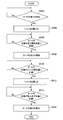
- FIG. 9 is a flowchart conceptually showing processing of the automatic transaction apparatus 100 in the present embodiment.
- the automatic transaction apparatus 100 waits until it detects the insertion of the magnetic card 10 (step S502). Specifically, the insertion detection sensor 127 detects the magnetic card 10 inserted through the card insertion unit 121. Then, the operation control unit detects the insertion of the magnetic card 10 based on the detection result of the insertion detection sensor 127.
- the automatic transaction apparatus 100 opens the shutter 122 (step S504). Specifically, when the magnetic card 10 is detected by the insertion detection sensor 127, the operation control unit instructs the shutter 122 drive device to open the shutter. Then, the driving device that receives the instruction opens the shutter 122.
- the automatic transaction apparatus 100 waits until the tip of the magnetic card 10 reaches the inhalation start position (step S506). Specifically, the position detection sensor 128 detects the magnetic card 10 that passes through the shutter 122 and reaches the suction start position.
- the automatic transaction apparatus 100 starts inhaling the magnetic card 10 (step S508). Specifically, when the magnetic card 10 is detected by the position detection sensor 128, the operation control unit issues a rotation start instruction to the driving devices for the transport roller pairs 123 to 125. Then, the drive device that receives the instruction starts the rotation of the drive motor, whereby the rotation of the conveyance rollers of the conveyance roller pairs 123 to 125 is started, and the suction of the magnetic card 10 is started.
- the automatic transaction apparatus 100 stands by until the tip of the magnetic card 10 reaches the shutter closed position (step S510). Specifically, the position detection sensor 129 detects the magnetic card 10 that is transported through the transport roller pair 123.
- the automatic transaction apparatus 100 closes the shutter 122 (step S512). Specifically, when the magnetic card 10 is detected by the position detection sensor 129, the operation control unit issues a shutter closing instruction to the driving device of the shutter 122. Then, the driving device that receives the instruction closes the shutter 122.
- the automatic transaction apparatus 100 waits until the tip of the magnetic card 10 reaches the inhalation completion position (step S514). Specifically, the position detection sensor 130 detects the magnetic card 10 that is transported through the transport roller pair 124.
- the automatic transaction apparatus 100 stops inhaling the magnetic card 10 (step S516). Specifically, when the magnetic card 10 is detected by the position detection sensor 130, the operation control unit issues a rotation stop instruction to the driving devices of the transport roller pairs 123 to 125. Then, the drive device that receives the instruction stops the rotation of the drive motor, thereby stopping the rotation of the conveyance rollers of the conveyance roller pairs 123 to 125 and stopping the suction of the magnetic card 10.
- the automatic transaction apparatus 100 reads information from the magnetic card 10 during steps S512 to S516.
- the magnetic head pair 126 reads information from the magnetic stripe of the magnetic card 10 being conveyed.
- reading of embossing or the like may be performed separately.
- the automatic transaction apparatus 100 includes the card insertion part 121 formed by protruding one direction of the magnetic card 10 and protruding in the direction opposite to the insertion direction, and the card insertion part. And a pair of conveying rollers 123 to 125 for sucking the magnetic card 10 inserted into 121. And the card insertion part 121 has a notch part formed so that it may become concave in the direction opposite to an insertion direction, The length from the card insertion port in the edge part of the insertion direction of a notch part to an inhalation start position Is shorter than the length of the magnetic card 10 in the insertion direction.
- the automatic transaction apparatus 100 also includes a position detection sensor 128 that detects the presence or absence of the magnetic card 10 at the detection position, and a suction operation of the conveyance roller pairs 123 to 125 according to the presence or absence of the magnetic card 10 detected by the position detection sensor 128.
- An operation control unit for controlling The inhalation start position is a detection position of the position detection sensor 128. For this reason, if the magnetic card 10 is not inserted to the inhalation start position, the inhalation is not started, so that the magnetic card 10 is accidentally inhaled with the skimming device attached, and the information on the magnetic card 10 may be illegally read. Can be reduced.
- the automatic transaction apparatus 100 includes a magnetic head pair 126 that reads information on the magnetic card 10.
- the detection position of the position detection sensor 128 is any position in the insertion direction of the card insertion portion 121 and in the direction opposite to the insertion direction of the magnetic head pair 126 in the conveyance path of the magnetic card 10. Therefore, by providing a certain degree of freedom with respect to the suction start position, the suction start position can be determined according to the length of the cutout portion in the insertion direction or the length of the card insertion portion 121 in the protruding direction. It is possible to widen the range of selection for the shape of the card insertion portion 121.
- the detection position of the position detection sensor 128 is any position in the direction orthogonal to the insertion direction passing through the position where the conveyance roller pair 123 and the magnetic card 10 are in contact with each other in the conveyance path of the magnetic card 10.
- the conveyance roller pair 123 is provided in the insertion direction with respect to the card insertion portion 121 and in the direction opposite to the insertion direction with respect to the magnetic head pair 126. For this reason, the conveyance roller is not rotated until the conveyance roller pair 123 and the magnetic card 10 come into contact with each other, thereby further reducing the possibility that the magnetic card 10 inserted with the skimming device attached is accidentally inhaled. It becomes possible to make it.
- the detection position of the position detection sensor 128 is any other position in the conveyance path of the magnetic card 10 where each conveyance roller constituting the conveyance roller pair 123 is in contact with the conveyance roller pair 123 and the magnetic card 10. It is any position in the direction orthogonal to the insertion direction that passes through positions closer to each other than the position. For this reason, even if the magnetic card 10 accidentally contacts the transport roller pair 123 with the skimming device attached, the transport roller is not rotated if the magnetic card 10 is not pushed further into the back. Accordingly, it is possible to further reduce the possibility that the magnetic card 10 inserted with the skimming device attached is accidentally inhaled.
- the notch is formed at a position where a straight line passing through the magnetic head pair 126 and parallel to the insertion direction passes. For this reason, the magnetic stripe of the magnetic card 10 to be sucked passes through the notch. Therefore, even when a skimming device whose horizontal width is shorter than the width of the card insertion portion 121 is attached, if the magnetic head of the skimming device is not installed in the notch, the data on the magnetic card 10 can be read. Have difficulty. Further, when the magnetic head is installed in the cutout portion, it becomes difficult to push the magnetic card 10, so that the magnetic card 10 is not inhaled and the user can notice the skimming device and prevent illegal reading of data. Is possible.
- a part of the card insertion part 121 adjacent to the card insertion slot may be formed so as to protrude outside the automatic transaction apparatus 100.
- the end of the card insertion portion 121 in the direction opposite to the insertion direction is formed such that a portion that contacts only one side of the long side of the card insertion slot protrudes.
- the protruding portion is also referred to as a stage portion.
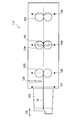
- FIG. 10 is a diagram showing an internal structure viewed from the side of the card handling unit 112 of the automatic transaction apparatus 100 according to the first modification of the present embodiment
- FIG. 11 is a first modification of the present embodiment. It is a figure which shows the internal structure seen from the upper surface of the card
- the card handling unit 112 includes the card insertion unit 121, the shutter 122, the transport roller pairs 123 to 125, the magnetic head pair 126, the insertion detection sensor 127, and the like, as shown in FIGS. Position detection sensors 128 to 130 are provided.
- the end of the card insertion portion 121 opposite to the insertion direction is formed such that a portion that contacts only one side of the long side of the card insertion slot protrudes.
- a portion that contacts only one side of the long side of the card insertion slot protrudes.
- the portion below the card insertion slot protrudes by a length D3 in the direction opposite to the insertion direction from the other portions. Can be done. Therefore, when the customer inserts the magnetic card 10, the customer makes it easy for the customer to insert the magnetic card 10 into the card insertion slot by applying the tip of the magnetic card 10 to the stage unit and sliding the stage on the stage unit.
- the end of the card insertion portion 121 in the direction opposite to the insertion direction is formed such that a portion that contacts only one side of the long side of the card insertion slot protrudes.
- the stage portion is provided at a lower portion than the card insertion port of the card insertion portion 121.
- the stage portion may be provided at a portion higher than the card insertion port of the card insertion portion 121.
- FIG. 11 shows an example in which the entire range of the lower part protrudes from the card insertion slot, but only a part of the lower part protrudes from the card insertion slot that contacts only the lower side of the card insertion slot. Also good.
- the stage part demonstrated the example formed by protruding a part of card insertion part 121, the stage part may be formed by cutting off with a part of card insertion part 121.
- the card handling unit 112 is formed so that the suction of the magnetic card 10 is not started unless the magnetic card 10 is inserted into the card insertion unit 121 up to the rear end of the magnetic card 10. May be. Specifically, the card handling unit 112 is formed such that the length from the suction start position to the end in the direction opposite to the insertion direction of the card insertion unit 121 is longer than the length of the magnetic card 10 in the insertion direction.
- the card handling unit 112 extends from a contact point of each conveyance roller of the conveyance roller pair 123 that is a detection position of the position detection sensor 128 to an end portion in a direction opposite to the insertion direction of the card insertion unit 121. Is formed to be longer than the length D1 in the insertion direction of the magnetic card 10.
- the length from the inhalation start position to the end in the direction opposite to the insertion direction of the card insertion portion 121 is longer than the length in the insertion direction of the magnetic card 10. long. For this reason, in a state where the skimming device is attached, it becomes difficult to push the rear end of the magnetic card 10 in the insertion direction more than the end of the card insertion portion 121, and skimming can be prevented more reliably.
- the skimming device is attached because the suction of the magnetic card 10 is not started in the state where the skimming device is attached to the card insertion portion 121. It is possible to prevent illegal reading of the ten pieces of information.
- the magnetic card 10 is inserted with the long side direction of the card as the insertion direction, but the present invention is not limited to such an example.
- the magnetic card 10 may be inserted with the short side direction of the card as the insertion direction.
- the card handling unit 112 has been described as including the position detection sensors 128 to 130. However, another position detection sensor may be included. For example, a separate position detection sensor may be provided between the position detection sensors 128 and 129.
- control unit 101 that controls the entire operation of the automatic transaction apparatus 100 may be configured by dedicated hardware, and a CPU (Central Processing Unit) built in the automatic transaction apparatus 100 is a ROM (Read Only Memory). ) May be realized by developing a program stored in a RAM (Random Access Memory) and executing the program. In addition to providing the program, a storage medium storing the program can also be provided.
- a CPU Central Processing Unit
- ROM Read Only Memory
- control unit 111 and the operation control unit may be configured by dedicated hardware, and the CPU built in the automatic transaction apparatus 100 expands the program stored in the ROM into the RAM. It may be realized by executing.
- a storage medium storing the program can also be provided.
Landscapes
- Physics & Mathematics (AREA)
- General Physics & Mathematics (AREA)
- Conveying Record Carriers (AREA)
- Control Of Vending Devices And Auxiliary Devices For Vending Devices (AREA)
Abstract
【課題】磁気カードからのデータの不正な読み取りを防止することが可能な自動取引装置を提供する。 【解決手段】カードが挿入され、前記カードの挿入方向と反対方向に突出して形成されるカード挿入部と、前記カード挿入部に挿入される前記カードを吸入するローラと、を備え、前記カード挿入部は、前記挿入方向と反対方向に凹となるように形成される切り欠き部を有し、前記切り欠き部の前記挿入方向の端部におけるカード挿入口から吸入開始位置までの長さは、前記カードの前記挿入方向の長さよりも短い、自動取引装置。
Description
本発明は、自動取引装置に関する。
近年、ATM(Automated Teller Machine)等の自動取引装置が普及し、銀行、駅構内またはコンビニエンスストア等の様々な場所に設置されるようになってきている。一般的に、自動取引装置においては、カードが挿入されると、当該カードの吸入が開始され装置内部に取り込まれる。
例えば、特許文献1では、カードおよび切符等の大きさの異なる2種類の媒体を吸入する装置であって、切符の挿入位置を誘導する形状を備える装置が開示されている。
しかし、特許文献1で開示される発明では、挿入される磁気カードからのデータの不正な読み取りを防止することが困難であるという問題があった。そこで、本発明は、上記問題に鑑みてなされたものであり、本発明の目的とするところは、磁気カードからのデータの不正な読み取りを防止することが可能な、新規かつ改良された自動取引装置を提供することにある。
上記課題を解決するために、本発明のある観点によれば、カードが挿入され、前記カードの挿入方向と反対方向に突出して形成されるカード挿入部と、前記カード挿入部に挿入される前記カードを吸入するローラと、を備え、前記カード挿入部は、前記挿入方向と反対方向に凹となるように形成される切り欠き部を有し、前記切り欠き部の前記挿入方向の端部におけるカード挿入口から吸入開始位置までの長さは、前記カードの前記挿入方向の長さよりも短い、自動取引装置が提供される。
また、検出位置における前記カードの有無を検出する検出部と、前記検出部によって検出される前記カードの有無に応じてローラの吸入動作を制御する制御部と、をさらに備え、 前記吸入開始位置は、前記検出位置であってもよい。
また、前記カードの情報を読み取る読取部をさらに備え、前記検出位置は、前記カードの搬送経路における、前記カード挿入部よりも前記挿入方向で、かつ前記読取部よりも前記挿入方向と反対の方向のいずれかの位置であってもよい。
また、前記検出位置は、前記カードの搬送経路における、第1のローラの組と挿入される前記カードとが接触する位置を通る、前記挿入方向と直交する方向のいずれかの位置であり、前記第1のローラの組は、前記カード挿入部よりも前記挿入方向で、かつ前記読取部よりも前記挿入方向と反対の方向に設けられてもよい。
また、前記検出位置は、前記カードの搬送経路における、前記第1のローラの組を構成する各ローラが前記接触する位置のうちのいずれの他の位置よりも互いに近接する位置を通る、前記挿入方向と直交する方向のいずれかの位置であってもよい。
また、前記切り欠き部は、前記読取部を通る、前記挿入方向と平行な直線が通る位置に形成されてもよい。
また、前記吸入開始位置から前記カード挿入部の前記挿入方向と反対方向の端部までの長さは、前記カードの前記挿入方向の長さよりも長くてもよい。
また、前記カード挿入部の前記挿入方向と反対方向の端部は、カード挿入口の長辺の一側にのみ接する部分が突出して形成されてもよい。
以上説明したように本発明によれば、磁気カードからのデータの不正な読み取りを防止することが可能な自動取引装置が提供される。
以下に添付図面を参照しながら、本発明の好適な実施の形態について詳細に説明する。なお、本明細書及び図面において、実質的に同一の機能構成を有する構成要素については、同一の符号を付することにより重複説明を省略する。
<1.従来技術の課題>
まず、従来の自動取引装置における課題を説明する。図1は、従来の自動取引装置200の斜視図である。
まず、従来の自動取引装置における課題を説明する。図1は、従来の自動取引装置200の斜視図である。
従来の自動取引装置200は、図1に示したように、カードおよび明細票取扱部202、通帳取扱部203、紙幣取扱部204、硬貨取扱部205および表示入力部206を備える。
カードおよび明細票取扱部202は、カードおよび明細票の吸入、排出および発行等の処理を行い、通帳取扱部203は、通帳の吸入および排出ならびに記帳等の処理を行う。紙幣取扱部204は、紙幣の入出金処理を行い、硬貨取扱部205は、硬貨の入出金処理を行う。表示入力部206は、取引内容の表示および取引の際の入力操作の受付け等を行う。さらに、カードおよび明細票取扱部202を構成するカード取扱部210について、図2および図3を参照して説明する。図2は、従来の自動取引装置200に係るカード取扱部210の側面から見た内部構造を示す図であり、図3は、従来の自動取引装置200に係るカード取扱部210の上面から見た内部構造を示す図である。
カード取扱部210は、図2および図3に示したように、カード挿入部211、シャッタ212、搬送ローラ対213~215、磁気ヘッド対216、挿入検出センサ217ならびに位置検出センサ218および219を備える。
カード挿入部211に近接して配置される挿入検出センサ217により磁気カード10の挿入が検出されると、搬送ローラ対213~215により磁気カード10がカード取扱部210の本体部に引き込まれる。そして、カード取扱部210の本体部に配置される磁気ヘッド対216により磁気カード10からデータが読み取られる。
しかし、従来の自動取引装置200においては、カード挿入部211付近に磁気ヘッド等のカード情報読取装置(以下、スキミング装置とも称する。)が取り付けられ、磁気カード10から不正にデータが読み取られる場合があった。そこで、本発明では、磁気カード10からのデータの不正な読み取り(以下、スキミングとも称する。)を防止することが可能な自動取引装置を提供する。以下、本発明の一実施形態に係る自動取引装置の構成および処理について順次説明する。
<2.本発明の一実施形態>
以上、従来の自動取引装置200の課題について説明した。次に、本発明の一実施形態に係る自動取引装置100について説明する。
以上、従来の自動取引装置200の課題について説明した。次に、本発明の一実施形態に係る自動取引装置100について説明する。
<2-1.装置の構成>
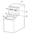
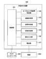
まず、図4および図5を参照して、本発明の一実施形態に係る自動取引装置100の構成について説明する。図4は、本発明の一実施形態に係る自動取引装置100の斜視図であり、図5は、本実施形態に係る自動取引装置100の機能および関連する外部機能の概略的な構成を示すブロック図である。
まず、図4および図5を参照して、本発明の一実施形態に係る自動取引装置100の構成について説明する。図4は、本発明の一実施形態に係る自動取引装置100の斜視図であり、図5は、本実施形態に係る自動取引装置100の機能および関連する外部機能の概略的な構成を示すブロック図である。
自動取引装置100は、図4および図5に示したように、制御部101、カードおよび明細票取扱部102、通帳取扱部103、紙幣取扱部104、硬貨取扱部105、表示入力部106および電源部107を備える。また、自動取引装置100は、ホストコンピュータ300および外部の電源400と接続される。
制御部101は、自動取引装置100の動作全体を制御する。具体的には、制御部101は、上述したカードおよび明細票取扱部102等の各機能の動作を制御する。また、制御部101は、外部装置であるホストコンピュータ300との間で通信を行う。例えば、制御部101は、取引処理の際にホストコンピュータ300との間でデータの送受信を行い、自動取引装置100の各機能に受信されるデータを提供する。
カードおよび明細票取扱部102は、カードの吸入および排出、吸入されるカードについてのデータの読み書き、ならびにカードの管理等を行う。例えば、カードおよび明細票取扱部102は、挿入される磁気カード、IC(integrated circuit)カードまたは振込カード等のカードのデータを読み取り、もしくは当該カードにデータを書き込む。また、カードおよび明細票取扱部102は、明細票の印字、発行および回収等を行う。なお、カードおよび明細票取扱部102の詳細については後述する。
通帳取扱部103は、通帳の吸入および排出、ならびに吸入される通帳についてデータ読み書きおよび印字等を行う。例えば、通帳取扱部103は、通帳入出口を通じて通帳を吸入し、吸入される通帳の持ち主を判別して、判別される持ち主のデータに基づく記帳等を行う。
紙幣取扱部104は、紙幣の入出金処理を行う。例えば、紙幣取扱部104は、紙幣の預け入れ、払い出し、計数、真偽認識および回収等を行う。また、硬貨取扱部105は、硬貨の入出金処理を行う。例えば、硬貨取扱部105は、硬貨の預け入れ、払い出し、計数、真偽認識および回収等を行う。
表示入力部106は、取引に関する情報を顧客に向けて表示し、顧客によって行われる入力操作を受け付ける。例えば、表示入力部106は、LCD(Liquid Crystal Display)等のディスプレイを用いたタッチパネル等であり得る。
電源部107は、外部の電源400から供給される電力を自動取引装置100の各部に提供する。例えば、電源部107は、制御部101の指示に基づいて、外部の電源400から供給される電力に基づく自動取引装置100の各部に向けた電力供給の開始および停止を行う。
(カードおよび明細票取扱部の詳細)
次に、図6を参照してカードおよび明細票取扱部102の構成の詳細について説明する。図6は、本実施形態に係る自動取引装置100のカードおよび明細票取扱部102の概略的な機能構成を示すブロック図である。
次に、図6を参照してカードおよび明細票取扱部102の構成の詳細について説明する。図6は、本実施形態に係る自動取引装置100のカードおよび明細票取扱部102の概略的な機能構成を示すブロック図である。
カードおよび明細票取扱部102は、図6に示したように、制御部111、カード取扱部112、カード印字部113、カード発行部114、カード取込部115、明細票印字部116、明細票供給部117および明細票取込部118を備える。
制御部111は、カードおよび明細票取扱部102の動作全体を制御する。例えば、制御部111は、上述したカード取扱部112等の各機能の動作を制御する。
カード取扱部112は、カードの吸入および排出、ならびに吸入されるカードについてデータの読み書きを行う。例えば、カード取扱部112は、自動取引装置100の内部に吸入される磁気カードもしくはICカードについてデータの読み取りおよび書き込み、または吸入されるカードの表面に形成されるエンボス等の読み取り等を行う。
カード印字部113は、カードの券面への印字を行う。例えば、カード印字部113は、振込カード等の券面に取引結果等の情報を印字する。
カード発行部114は、カードを新たに発行する。例えば、自動取引装置100は新規カードが装填される装填部を備え、カード発行部114は装填部から新規カードを繰り出してカードを発行する。
カード取込部115は、排出されるカードを回収する。例えば、カード取込部115は、取引後に排出されるカードを顧客が取り忘れた場合等に、一定時間放置されたカードを取り込んで収納する。
明細票印字部116は、明細票を発行する。例えば、明細票印字部116は、取引結果等を用紙に印字し、当該用紙を切断して明細票を発行する。
明細票供給部117は、明細票となる用紙を供給する。例えば、明細票供給部117は、明細票印字部116の動作に合わせて、明細票となる用紙を明細票印字部116に供給する。
明細票取込部118は、排出される明細票を回収する。例えば、明細票取込部118は、明細票印字部116により発行され、排出された明細票が顧客により受け取られないまま一定期間が経過した場合、当該明細票を回収し収納する。なお、明細票取込部118は、自動取引装置100の障害情報が記載された帳票、精査票および保守履歴票等も明細票と同様に回収する。
(カード取扱部112の詳細)
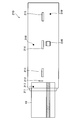
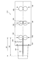
さらに、図7および図8を参照してカード取扱部112の構成の詳細について説明する。図7は、本実施形態に係る自動取引装置100のカード取扱部112の側面から見た内部構造を示す図であり、図8は、本実施形態に係る自動取引装置100のカード取扱部112の上面から見た内部構造を示す図である。
さらに、図7および図8を参照してカード取扱部112の構成の詳細について説明する。図7は、本実施形態に係る自動取引装置100のカード取扱部112の側面から見た内部構造を示す図であり、図8は、本実施形態に係る自動取引装置100のカード取扱部112の上面から見た内部構造を示す図である。
カード取扱部112は、図7および図8に示したように、カード挿入部121、シャッタ122、搬送ローラ対123~125、磁気ヘッド対126、挿入検出センサ127ならびに位置検出センサ128~130を備える。また、カード取扱部112は動作制御部(図示せず。)を備える。
カード挿入部121は、磁気カード10の挿入を受け付ける。具体的には、カード挿入部121は、カード挿入口を有し、カード挿入口に挿入される1種類の磁気カード10を自動取引装置100の内部に誘導する。また、カード挿入部121は、磁気カード10の挿入方向(以下、挿入方向とも称する。)と反対方向に突出して形成される。例えば、図7に示したように、磁気カード10は、カード挿入口(図示せず。)を介してカード挿入部121内部を通過し、カード取扱部112の本体部、すなわち自動取引装置100の内部に誘導される。ここで、1種類のカードには、挿入方向と水平に直交する方向の長さが同じであるカードが含まれる。なお、カード挿入部121は、自動取引装置100の筐体と一体として形成されてもよく、当該筐体に取り付けられてもよい。
また、カード挿入部121は、磁気カード10の挿入方向と反対方向に凹となるように形成される切り欠き部を有する。具体的には、カード挿入部121には、切り欠き部の挿入方向の端部におけるカード挿入口から磁気カード10の吸入開始位置までの長さが磁気カード10の挿入方向の長さよりも短くなるように、切り欠き部が形成される。
例えば、図8に示したように、切り欠き部はカード挿入部121の挿入方向と反対方向の端部に設けられ、挿入方向と反対方向に凹となるように形成される。さらに、切り欠き部は、図8に示したように、切り欠き部の挿入方向の端部におけるカード挿入口から磁気カード10の吸入開始位置までの長さD2が磁気カード10の挿入方向の長さD1よりも短くなるように形成される。なお、吸入開始位置は、磁気カード10の挿入方向の先端が当該吸入開始位置に到達した際に、磁気カード10を吸入する動作が開始される位置である。当該吸入開始位置は、後述する位置検出センサ128の検出位置によって実質的に決定される。
さらに、切り欠き部は、後述する磁気ヘッド対126と対応する位置に形成される。具体的には、切り欠き部は、磁気ヘッド対126を通る、挿入方向と平行な直線が通る位置に形成される。例えば、図8に示したように、切り欠き部は、磁気ヘッド対126、すなわち磁気カード10の磁気ストライプを通る挿入方向の直線が通るカード挿入部121の端部に形成される。
なお、切り欠き部の形成される位置は、磁気ヘッド対126を通る、挿入方向と平行な直線のすべてが通る位置に形成され、切り欠き部の水平方向の幅は、磁気ヘッド対126の水平方向の幅、すなわち磁気カード10の磁気ストライプの幅と同程度の長さであることが望ましい。この場合、切り欠き部にスキミング装置の磁気ヘッドが設置されても、磁気ヘッドと切り欠き部との水平方向の間に隙間が生じないため、磁気カード10を押し込むことが困難となる。その結果、磁気カード10が吸入されず、磁気カード10のデータが読み取られることがないので、スキミングのより確実な防止が可能となる。
なお、切り欠き部の形状は、図8に示した形状に限定されない。例えば、図8に示した切り欠き部の形状は磁気カード10の表面に対して垂直方向に貫通されているが、切り欠き部の形状は貫通されずに、カード挿入口の周辺のカード挿入部121の一部が切り取られたような形状であってもよい。また、挿入方向と直交する方向の幅は、指の幅程度の長さであってもよく、指の幅よりも長くてもよい。
シャッタ122は、磁気カード10の挿入に応じて開閉される。具体的には、シャッタ122は、磁気カード10が挿入された際に開けられ、磁気カード10の吸入が完了した際に閉められる。例えば、自動取引装置100は、シャッタ122の開閉動作を制御する駆動装置を備え、駆動装置は動作制御部の指示に従ってシャッタ122の開閉を行う。
搬送ローラ対123~125は、挿入される磁気カード10を搬送する。具体的には、搬送ローラ対123~125は、それぞれ対抗する複数の搬送ローラの組で構成され、磁気カード10は、当該複数の搬送ローラの間に挟まれ、各搬送ローラが挿入方向に回転することによって挿入方向に搬送される。例えば、図7に示したように、搬送ローラ対123~125は、それぞれ2つの搬送ローラの組で構成される。例えば、搬送ローラ対123の有する2つの搬送ローラが互いに近接する位置付近まで磁気カード10が挿入された際に、挿入方向にそれぞれ回転する各搬送ローラと磁気カード10との摩擦力によって磁気カード10は挿入方向に搬送される。
また、搬送ローラ対123~125は、動作制御部の指示に基づいて動作する。具体的には、搬送ローラ対123~125の各搬送ローラは、動作制御部による指示に基づいて回転を開始し、および停止する。例えば、自動取引装置100は、搬送ローラ対123~125の各搬送ローラの回転を制御する駆動装置を備え、動作制御部は当該駆動装置に動作を指示する。例えば、駆動装置は、DC(Direct Current)サーボモータまたはパルスモータ等の駆動モータを有し、当該駆動モータの回転を動力源として搬送ローラ対123~125を回転させる。なお、駆動装置により回転させられていない状態の各搬送ローラは挿入される磁気カード10との摩擦によっても回転され得る。
磁気ヘッド対126は、読取部として、磁気カード10の有する情報を読み取る。例えば、磁気ヘッド対126は、接触する磁気カード10が搬送されてスライドされることにより、磁気カード10の磁気ストライプに記憶される情報を読み取る。なお、磁気カード10はカードの一面に磁気層が付されたカードであってもよい。
挿入検出センサ127は、挿入される磁気カード10を検出する。具体的には、挿入検出センサ127は、カード挿入部121よりも挿入方向であって、シャッタ122よりも挿入方向と反対方向に配置され、磁気カード10の有無を検出する。そして、動作制御部は、挿入検出センサ127の検出結果を用いて磁気カード10の挿入を検出する。例えば、挿入検出センサ127は、発光センサおよび受光センサで構成される光学センサ等であり得る。図7に示したように、挿入検出センサ127を構成する発光センサおよび受光センサが垂直方向に対となるように配置され、磁気カード10が検出位置に到達した際に、発光センサの受光センサに向けて発する光が遮られることにより挿入検出センサ127は磁気カード10を検出する。すなわち、検出位置は、挿入される磁気カード10の挿入経路と挿入検出センサ127の光路との交点である。なお、挿入検出センサ127は、磁気カード10を検出することが可能なセンサであれば、センサの種類は限定されない。例えば、挿入検出センサ127は、発光センサおよび受光センサを一体として備え、発光センサが発する光の反射光を受光センサが受光し、受光レベルに基づいて挿入検出センサ127は磁気カード10の有無を検出してもよい。
位置検出センサ128~130は、磁気カード10を検出する。具体的には、位置検出センサ128~130は、固定的に配置され、検出位置における磁気カード10の有無を検出する。動作制御部は、位置検出センサ128~130の検出結果を用いて磁気カード10の位置を検出する。例えば、位置検出センサ128~130は、挿入検出センサ127と同様に、発光センサおよび受光センサで構成される光学センサ等であり得る。
また、位置検出センサ128は、磁気カード10の搬送経路における、カード挿入部121よりも挿入方向で、かつ磁気ヘッド対126よりも挿入方向と反対の方向のいずれかの位置を検出位置とする。例えば、位置検出センサ128は、磁気カード10の搬送経路における、搬送ローラ対123と挿入される磁気カード10とが接触する位置を通る、挿入方向と直交する方向のいずれかの位置を検出位置とする。なお、搬送ローラ対123は、カード挿入部121よりも挿入方向で、かつ磁気ヘッド対126よりも挿入方向と反対の方向に設けられる。
より具体的には、位置検出センサ128は、磁気カード10の搬送経路における、搬送ローラ対123を構成する各搬送ローラが、搬送ローラ対123と磁気カード10とが接触する位置のうちのいずれの他の位置よりも互いに近接する位置を通る、挿入方向と直交する方向のいずれかの位置を検出位置とする。例えば、図8に示したように、搬送ローラ対123は、カード挿入部121よりも挿入方向で、かつ磁気ヘッド対126よりも挿入方向と反対の方向に設けられる。そして、位置検出センサ128は、磁気カード10の搬送経路上であって、搬送ローラ対123の中心、すなわち各搬送ローラが最も接近する位置を通る直線上に配置される。
なお、図8に示したように、位置検出センサ129は、搬送ローラ対124の中心を通る直線上に配置され、位置検出センサ130は、搬送ローラ対125の中心よりも挿入方向の位置を通る直線上に配置される。
また、上記では、挿入検出センサ127および位置検出センサ128~130は、発光センサおよび受光センサが垂直方向に対向するように配置される例を説明したが、発光センサおよび受光センサが水平方向に対向するように配置されてもよい。
動作制御部は、カード取扱部112の動作全体を制御する。具体的には、動作制御部は、搬送ローラ対123~125の動作を制御する。より具体的には、動作制御部は、位置検出センサ128~130によって検出される磁気カード10の有無に応じて搬送ローラ対123~125の各搬送ローラの吸入動作を制御する。例えば、動作制御部は、位置検出センサ128によって磁気カード10が検出された際に、搬送ローラ対123~125の駆動装置に回転開始指示を行う。そして、当該指示を受ける駆動装置が駆動モータの回転を開始させることによって搬送ローラ対123~125の各搬送ローラが回転され、磁気カード10が吸入される。また、動作制御部は、位置検出センサ130によって磁気カード10が検出された際に、搬送ローラ対123~125の駆動装置に回転停止指示を行う。そして、当該指示を受ける駆動装置が駆動モータの回転を停止させることによって搬送ローラ対123~125の各搬送ローラの回転が停止され、磁気カード10の吸入が停止される。
また、動作制御部は、シャッタ122の開閉動作を制御する。具体的には、動作制御部は、挿入検出センサ127によって検出される磁気カード10の有無に応じてシャッタ122の開閉動作を制御する。例えば、動作制御部は、挿入検出センサ127によって磁気カード10が検出された際に、シャッタ122の開閉を制御する駆動装置にシャッタの開放指示を行う。そして、当該指示を受ける駆動装置によって、図7に示したように、磁気カード10が通過可能なようにシャッタ122が上方に移動される。また、動作制御部は、位置検出センサ129によって磁気カード10が検出された際に、シャッタ122の駆動装置にシャッタの閉鎖指示を行う。そして、当該指示を受ける駆動装置によって、シャッタ122が元の位置に下ろされる。
<2-2.装置の処理>
次に、本実施形態における自動取引装置100の処理について図9を参照して説明する。図9は、本実施形態における自動取引装置100の処理を概念的に示すフローチャートである。
次に、本実施形態における自動取引装置100の処理について図9を参照して説明する。図9は、本実施形態における自動取引装置100の処理を概念的に示すフローチャートである。
まず、自動取引装置100は、磁気カード10の挿入を検出するまで待機する(ステップS502)。具体的には、挿入検出センサ127は、カード挿入部121を通過して挿入される磁気カード10を検出する。そして、動作制御部は、挿入検出センサ127の検出結果に基づいて磁気カード10の挿入を検出する。
磁気カード10の挿入が検出された際に、自動取引装置100は、シャッタ122を開ける(ステップS504)。具体的には、挿入検出センサ127によって磁気カード10が検出された際に、動作制御部はシャッタ122の駆動装置に向けてシャッタ開放指示を行う。そして、当該指示を受ける駆動装置はシャッタ122を開放させる。
次に、自動取引装置100は、磁気カード10の先端が吸入開始位置に到達するまで待機する(ステップS506)。具体的には、位置検出センサ128は、シャッタ122を通過して吸入開始位置に到達する磁気カード10を検出する。
磁気カード10の先端が吸入開始位置に到達した際に、自動取引装置100は、磁気カード10の吸入を開始する(ステップS508)。具体的には、位置検出センサ128によって磁気カード10が検出された際に、動作制御部は搬送ローラ対123~125の駆動装置に回転開始指示を行う。そして、当該指示を受ける駆動装置が駆動モータの回転を開始させることにより、搬送ローラ対123~125の各搬送ローラの回転が開始され、磁気カード10の吸入が開始される。
次に、自動取引装置100は、磁気カード10の先端がシャッタ閉位置に到達するまで待機する(ステップS510)。具体的には、位置検出センサ129は、搬送ローラ対123を通過して搬送される磁気カード10を検出する。
磁気カード10の先端がシャッタ閉位置に到達した際に、自動取引装置100は、シャッタ122を閉じる(ステップS512)。具体的には、位置検出センサ129によって磁気カード10が検出された際に、動作制御部はシャッタ122の駆動装置に向けてシャッタ閉鎖指示を行う。そして、当該指示を受ける駆動装置はシャッタ122を閉鎖させる。
次に、自動取引装置100は、磁気カード10の先端が吸入完了位置に到達するまで待機する(ステップS514)。具体的には、位置検出センサ130は、搬送ローラ対124を通過して搬送される磁気カード10を検出する。
磁気カード10の先端が吸入完了位置に到達した際に、自動取引装置100は、磁気カード10の吸入を停止する(ステップS516)。具体的には、位置検出センサ130によって磁気カード10が検出された際に、動作制御部は搬送ローラ対123~125の駆動装置に回転停止指示を行う。そして、当該指示を受ける駆動装置は駆動モータの回転を停止させることにより、搬送ローラ対123~125の各搬送ローラの回転が停止され、磁気カード10の吸入が停止される。
なお、ステップS512~S516の間に、自動取引装置100は、磁気カード10から情報を読み取る。具体的には、磁気ヘッド対126は、搬送される磁気カード10の磁気ストライプから情報を読み取る。また、磁気ヘッド対126による情報の読み取りのほか、別途エンボスの読み取り等が行われてもよい。
このように、本発明の一実施形態によれば、自動取引装置100は、1種類の磁気カード10が挿入され、挿入方向と反対方向に突出して形成されるカード挿入部121と、カード挿入部121に挿入される磁気カード10を吸入する搬送ローラ対123~125と、を備える。そして、カード挿入部121は、挿入方向と反対方向に凹となるように形成される切り欠き部を有し、切り欠き部の挿入方向の端部におけるカード挿入口から吸入開始位置までの長さは、磁気カード10の挿入方向の長さよりも短い。このため、磁気カード10の後端が切り欠き部の挿入方向の端部まで押し込まれた際に、磁気カード10の先端が吸入開始位置に到達することとなる。したがって、カード挿入部121にスキミング装置が取り付けられた状態では、磁気カード10の後端を切り欠き部の挿入方向の端部まで押し込むことができない。そのため、磁気カード10の吸入が開始されないことにより、スキミング装置が取り付けられていることが発見され、磁気カード10の情報の不正な読み取りを防止することが可能となる。
また、自動取引装置100は、検出位置における磁気カード10の有無を検出する位置検出センサ128と、位置検出センサ128によって検出される磁気カード10の有無に応じて搬送ローラ対123~125の吸入動作を制御する動作制御部と、を備える。そして、吸入開始位置は、位置検出センサ128の検出位置である。このため、吸入開始位置まで磁気カード10が挿入されないと吸入が開始されないことにより、スキミング装置が取り付けられた状態で偶然に磁気カード10が吸入され、磁気カード10の情報が不正に読み取られる可能性を低下させることが可能となる。
また、自動取引装置100は、磁気カード10の情報を読み取る磁気ヘッド対126を備える。そして、位置検出センサ128の検出位置は、磁気カード10の搬送経路における、カード挿入部121よりも挿入方向で、かつ磁気ヘッド対126よりも挿入方向と反対の方向のいずれかの位置である。このため、吸入開始位置についてある程度の自由度を持たせることにより、切り欠き部の挿入方向の長さ、またはカード挿入部121の突出方向の長さ等に応じて吸入開始位置を決めることができ、カード挿入部121の形状について選択の幅を広げることが可能となる。
また、位置検出センサ128の検出位置は、磁気カード10の搬送経路における、搬送ローラ対123と磁気カード10とが接触する位置を通る、挿入方向と直交する方向のいずれかの位置である。そして、搬送ローラ対123は、カード挿入部121よりも挿入方向で、かつ磁気ヘッド対126よりも挿入方向と反対の方向に設けられる。このため、搬送ローラ対123と磁気カード10とが接触するまで、搬送ローラが回転されないことにより、スキミング装置が取り付けられた状態で挿入される磁気カード10が偶然に吸入される可能性をより低下させることが可能となる。
また、位置検出センサ128の検出位置は、磁気カード10の搬送経路における、搬送ローラ対123を構成する各搬送ローラが、搬送ローラ対123と磁気カード10とが接触する位置のうちのいずれの他の位置よりも互いに近接する位置を通る、挿入方向と直交する方向のいずれかの位置である。このため、スキミング装置が取り付けられた状態で偶然に磁気カード10が搬送ローラ対123と接触する場合であっても、さらに磁気カード10が奥に押し込まれない場合には搬送ローラが回転されない。これにより、スキミング装置が取り付けられた状態で挿入される磁気カード10が偶然に吸入される可能性をさらに低下させることが可能となる。
また、切り欠き部は、磁気ヘッド対126を通る、挿入方向と平行な直線が通る位置に形成される。このため、吸入される磁気カード10の磁気ストライプが切り欠き部を通ることになる。そのため、水平方向の幅がカード挿入部121の幅よりも短いスキミング装置が取り付けられる場合であっても、スキミング装置の磁気ヘッドが切り欠き部に設置されなければ磁気カード10のデータを読み取ることは困難である。また、切り欠き部に磁気ヘッドが設置されると、磁気カード10を押し込むことが難しくなるため、磁気カード10が吸入されず、ユーザはスキミング装置に気付くことができ、データの不正な読み取りの防止が可能となる。
<2-3.変形例>
以上、本発明の一実施形態について説明した。なお、本実施形態は、上述の例に限定されない。以下に、本実施形態の第1、第2の変形例について説明する。
以上、本発明の一実施形態について説明した。なお、本実施形態は、上述の例に限定されない。以下に、本実施形態の第1、第2の変形例について説明する。
(第1の変形例)
本実施形態の第1の変形例として、カード挿入口に隣接するカード挿入部121の一部は自動取引装置100の外部に突出するように形成されてもよい。具体的には、カード挿入部121の挿入方向と反対方向の端部は、カード挿入口の長辺の一側にのみ接する部分が突出して形成される。以下、当該突出部分をステージ部とも称する。さらに、本変形例のカード挿入部121の形状について、図10および図11を参照して詳細に説明する。図10は、本実施形態の第1の変形例に係る自動取引装置100のカード取扱部112の側面から見た内部構造を示す図であり、図11は、本実施形態の第1の変形例に係る自動取引装置100のカード取扱部112の上面から見た内部構造を示す図である。
本実施形態の第1の変形例として、カード挿入口に隣接するカード挿入部121の一部は自動取引装置100の外部に突出するように形成されてもよい。具体的には、カード挿入部121の挿入方向と反対方向の端部は、カード挿入口の長辺の一側にのみ接する部分が突出して形成される。以下、当該突出部分をステージ部とも称する。さらに、本変形例のカード挿入部121の形状について、図10および図11を参照して詳細に説明する。図10は、本実施形態の第1の変形例に係る自動取引装置100のカード取扱部112の側面から見た内部構造を示す図であり、図11は、本実施形態の第1の変形例に係る自動取引装置100のカード取扱部112の上面から見た内部構造を示す図である。
カード取扱部112は、第1の実施形態と同様、図10および図11に示したように、カード挿入部121、シャッタ122、搬送ローラ対123~125、磁気ヘッド対126、挿入検出センサ127ならびに位置検出センサ128~130を備える。
カード挿入部121の挿入方向と反対方向の端部は、カード挿入口の長辺の一側にのみ接する部分が突出して形成される。例えば、図10に示したように、カード挿入部121の挿入方向と反対方向の端部のうち、カード挿入口よりも下方部分が他の部分よりも挿入方向と反対方向に長さD3だけ突出され得る。そのため、顧客が磁気カード10を挿入する際に、顧客が磁気カード10の先端をステージ部に当て、ステージ部上を滑らせることにより、顧客は磁気カード10をカード挿入口に挿入し易くなる。
このように、本実施形態の第1の変形例によれば、カード挿入部121の挿入方向と反対方向の端部は、カード挿入口の長辺の一側にのみ接する部分が突出して形成される。このため、カード挿入部121にステージ部が設けられることにより、スキミングを防止しながら顧客の操作性を向上させることが可能となる。
なお、上記では、ステージ部はカード挿入部121のカード挿入口よりも下方部分に設けられる例を説明したが、ステージ部はカード挿入部121のカード挿入口よりも上方部分に設けられてもよい。また、図11では、カード挿入口よりも下方部分の全範囲が突出される例を示したが、カード挿入口の下辺のみに接する、カード挿入口よりも下方部分の一部のみが突出されてもよい。また、ステージ部はカード挿入部121の一部を突出させることによって形成される例を説明したが、ステージ部はカード挿入部121の一部と切り取ることによって形成されてもよい。
(第2の変形例)
本実施形態の第2の変形例として、カード取扱部112は、磁気カード10の後端まで磁気カード10がカード挿入部121内に挿入されないと、磁気カード10の吸入が開始されないように形成されてもよい。具体的には、カード取扱部112は、吸入開始位置からカード挿入部121の挿入方向と反対方向の端部までの長さが、磁気カード10の挿入方向の長さよりも長くなるように形成される。
本実施形態の第2の変形例として、カード取扱部112は、磁気カード10の後端まで磁気カード10がカード挿入部121内に挿入されないと、磁気カード10の吸入が開始されないように形成されてもよい。具体的には、カード取扱部112は、吸入開始位置からカード挿入部121の挿入方向と反対方向の端部までの長さが、磁気カード10の挿入方向の長さよりも長くなるように形成される。
例えば、カード取扱部112は、図7に示したように、位置検出センサ128の検出位置である搬送ローラ対123の各搬送ローラの接点からカード挿入部121の挿入方向と反対方向の端部までの長さが、磁気カード10の挿入方向の長さD1よりも長くなるように形成される。
このように、本実施形態の第2の変形例によれば、吸入開始位置からカード挿入部121の挿入方向と反対方向の端部までの長さが、磁気カード10の挿入方向の長さよりも長い。このため、スキミング装置が取り付けられた状態では磁気カード10の後端をカード挿入部121の端部よりも挿入方向に押し込むことが困難になり、スキミングをより確実に防止することが可能となる。
<3.むすび>
以上、本発明の一実施形態によれば、カード挿入部121にスキミング装置が取り付けられた状態では、磁気カード10の吸入が開始されないため、スキミング装置が取り付けられていることが発見され、磁気カード10の情報の不正な読み取りを防止することが可能となる。
以上、本発明の一実施形態によれば、カード挿入部121にスキミング装置が取り付けられた状態では、磁気カード10の吸入が開始されないため、スキミング装置が取り付けられていることが発見され、磁気カード10の情報の不正な読み取りを防止することが可能となる。
以上、添付図面を参照しながら本発明の好適な実施形態について詳細に説明したが、本発明はかかる例に限定されない。本発明の属する技術の分野における通常の知識を有する者であれば、請求の範囲に記載された技術的思想の範疇内において、各種の変更例または修正例に想到し得ることは明らかであり、これらについても、当然に本発明の技術的範囲に属するものと了解される。
例えば、上記実施形態では、磁気カード10はカードの長辺方向を挿入方向として挿入する例を説明したが、本発明はかかる例に限定されない。例えば、磁気カード10はカードの短辺方向を挿入方向として挿入されてもよい。
また、上記実施形態では、カード取扱部112は位置検出センサ128~130を備える例を説明したが、さらに別の位置検出センサが備えられてもよい。例えば、位置検出センサ128と129との間に別途位置検出センサが設けられてもよい。
また、例えば、自動取引装置100の動作全体を制御する制御部101は、専用のハードウェアによって構成されてもよく、自動取引装置100に内蔵されたCPU(Central Processing Unit)がROM(Read Only Memory)に記憶されたプログラムをRAM(Random Access Memory)に展開して実行することにより実現されてもよい。当該プログラムが提供され得るほか、当該プログラムを記憶させた記憶媒体も提供され得る。
また、制御部111および動作制御部も制御部101と同様に、専用のハードウェアによって構成されてもよく、自動取引装置100に内蔵されたCPUがROMに記憶されたプログラムをRAMに展開して実行することにより実現されてもよい。当該プログラムが提供され得るほか、当該プログラムを記憶させた記憶媒体も提供され得る。
10 磁気カード
100 自動取引装置
101 制御部
102 カードおよび明細票取扱部
103 通帳取扱部
104 紙幣取扱部
105 硬貨取扱部
106 表示入力部
107 電源部
111 制御部
112 カード取扱部
113 カード印字部
114 カード発行部
115 カード取込部
116 明細票印字部
117 明細票供給部
118 明細票取込部
121 カード挿入部
122 シャッタ
123、124、125 搬送ローラ対
126 磁気ヘッド対
127 挿入検出センサ
128、129、130 位置検出センサ
200 自動取引装置
300 ホストコンピュータ
400 電源
100 自動取引装置
101 制御部
102 カードおよび明細票取扱部
103 通帳取扱部
104 紙幣取扱部
105 硬貨取扱部
106 表示入力部
107 電源部
111 制御部
112 カード取扱部
113 カード印字部
114 カード発行部
115 カード取込部
116 明細票印字部
117 明細票供給部
118 明細票取込部
121 カード挿入部
122 シャッタ
123、124、125 搬送ローラ対
126 磁気ヘッド対
127 挿入検出センサ
128、129、130 位置検出センサ
200 自動取引装置
300 ホストコンピュータ
400 電源
Claims (8)
- カードが挿入され、前記カードの挿入方向と反対方向に突出して形成されるカード挿入部と、
前記カード挿入部に挿入される前記カードを吸入するローラと、
を備え、
前記カード挿入部は、前記挿入方向と反対方向に凹となるように形成される切り欠き部を有し、
前記切り欠き部の前記挿入方向の端部におけるカード挿入口から吸入開始位置までの長さは、前記カードの前記挿入方向の長さよりも短い、自動取引装置。 - 検出位置における前記カードの有無を検出する検出部と、
前記検出部によって検出される前記カードの有無に応じてローラの吸入動作を制御する制御部と、
をさらに備え、
前記吸入開始位置は、前記検出位置である、請求項1に記載の自動取引装置。 - 前記カードの情報を読み取る読取部をさらに備え、
前記検出位置は、前記カードの搬送経路における、前記カード挿入部よりも前記挿入方向で、かつ前記読取部よりも前記挿入方向と反対の方向のいずれかの位置である、請求項2に記載の自動取引装置。 - 前記検出位置は、前記カードの搬送経路における、第1のローラの組と挿入される前記カードとが接触する位置を通る、前記挿入方向と直交する方向のいずれかの位置であり、
前記第1のローラの組は、前記カード挿入部よりも前記挿入方向で、かつ前記読取部よりも前記挿入方向と反対の方向に設けられる、請求項3に記載の自動取引装置。 - 前記検出位置は、前記カードの搬送経路における、前記第1のローラの組を構成する各ローラが前記接触する位置のうちのいずれの他の位置よりも互いに近接する位置を通る、前記挿入方向と直交する方向のいずれかの位置である、請求項4に記載の自動取引装置。
- 前記切り欠き部は、前記読取部を通る、前記挿入方向と平行な直線が通る位置に形成される、請求項3に記載の自動取引装置。
- 前記吸入開始位置から前記カード挿入部の前記挿入方向と反対方向の端部までの長さは、前記カードの前記挿入方向の長さよりも長い、請求項1に記載の自動取引装置。
- 前記カード挿入部の前記挿入方向と反対方向の端部は、カード挿入口の長辺の一側にのみ接する部分が突出して形成される、請求項1に記載の自動取引装置。
Priority Applications (1)
| Application Number | Priority Date | Filing Date | Title |
|---|---|---|---|
| CN201580024312.9A CN106463016A (zh) | 2014-07-17 | 2015-04-27 | 自动交易装置 |
Applications Claiming Priority (2)
| Application Number | Priority Date | Filing Date | Title |
|---|---|---|---|
| JP2014-146555 | 2014-07-17 | ||
| JP2014146555A JP2016024525A (ja) | 2014-07-17 | 2014-07-17 | 自動取引装置 |
Publications (1)
| Publication Number | Publication Date |
|---|---|
| WO2016009697A1 true WO2016009697A1 (ja) | 2016-01-21 |
Family
ID=55078201
Family Applications (1)
| Application Number | Title | Priority Date | Filing Date |
|---|---|---|---|
| PCT/JP2015/062640 Ceased WO2016009697A1 (ja) | 2014-07-17 | 2015-04-27 | 自動取引装置 |
Country Status (3)
| Country | Link |
|---|---|
| JP (1) | JP2016024525A (ja) |
| CN (1) | CN106463016A (ja) |
| WO (1) | WO2016009697A1 (ja) |
Families Citing this family (2)
| Publication number | Priority date | Publication date | Assignee | Title |
|---|---|---|---|---|
| JP6935172B2 (ja) * | 2016-05-18 | 2021-09-15 | キヤノン電子株式会社 | 決済情報読取装置 |
| US10373417B1 (en) * | 2018-03-01 | 2019-08-06 | Verifone, Inc. | Systems, methods and devices for detecting unauthorized devices at transaction devices |
Citations (2)
| Publication number | Priority date | Publication date | Assignee | Title |
|---|---|---|---|---|
| JP3370516B2 (ja) * | 1996-06-18 | 2003-01-27 | 日本信号株式会社 | カードおよび券挿入口用フレーム |
| JP2011060064A (ja) * | 2009-09-11 | 2011-03-24 | Hitachi Omron Terminal Solutions Corp | 自動取引装置 |
Family Cites Families (7)
| Publication number | Priority date | Publication date | Assignee | Title |
|---|---|---|---|---|
| JPH05120461A (ja) * | 1991-10-30 | 1993-05-18 | Olympus Optical Co Ltd | カード駆動装置 |
| JP2001067514A (ja) * | 1999-08-31 | 2001-03-16 | Sankyo Seiki Mfg Co Ltd | 磁気カード取引装置 |
| JP4680048B2 (ja) * | 2005-12-13 | 2011-05-11 | 日立オムロンターミナルソリューションズ株式会社 | カード処理装置 |
| JP5030678B2 (ja) * | 2007-06-15 | 2012-09-19 | 日立オムロンターミナルソリューションズ株式会社 | 記録媒体処理装置 |
| JP5210900B2 (ja) * | 2009-01-23 | 2013-06-12 | 日立オムロンターミナルソリューションズ株式会社 | 取引処理装置 |
| JP5465155B2 (ja) * | 2010-11-16 | 2014-04-09 | 日立オムロンターミナルソリューションズ株式会社 | カード処理ユニット、および自動取引処理装置 |
| JP5698086B2 (ja) * | 2011-07-08 | 2015-04-08 | 日立オムロンターミナルソリューションズ株式会社 | 記録媒体受付装置 |
-
2014
- 2014-07-17 JP JP2014146555A patent/JP2016024525A/ja active Pending
-
2015
- 2015-04-27 WO PCT/JP2015/062640 patent/WO2016009697A1/ja not_active Ceased
- 2015-04-27 CN CN201580024312.9A patent/CN106463016A/zh active Pending
Patent Citations (2)
| Publication number | Priority date | Publication date | Assignee | Title |
|---|---|---|---|---|
| JP3370516B2 (ja) * | 1996-06-18 | 2003-01-27 | 日本信号株式会社 | カードおよび券挿入口用フレーム |
| JP2011060064A (ja) * | 2009-09-11 | 2011-03-24 | Hitachi Omron Terminal Solutions Corp | 自動取引装置 |
Also Published As
| Publication number | Publication date |
|---|---|
| JP2016024525A (ja) | 2016-02-08 |
| CN106463016A (zh) | 2017-02-22 |
Similar Documents
| Publication | Publication Date | Title |
|---|---|---|
| CN102119404A (zh) | 纸币存取款机 | |
| TWI390469B (zh) | Recording medium processing device | |
| US9640008B2 (en) | Cash transaction machine | |
| JP5465155B2 (ja) | カード処理ユニット、および自動取引処理装置 | |
| CN105303679B (zh) | 纸币处理装置 | |
| JP2008212196A (ja) | 遊技媒体処理装置 | |
| CN102129744B (zh) | 自动交易机和自动交易方法 | |
| JP5633363B2 (ja) | 自動取引装置、自動取引方法、及びプログラム | |
| JP2016024525A (ja) | 自動取引装置 | |
| JP5176705B2 (ja) | 自動取引装置 | |
| JP5142740B2 (ja) | 自動取引装置 | |
| JP5564767B2 (ja) | 自動取引装置 | |
| JP6225738B2 (ja) | 自動取引装置 | |
| JP5494765B2 (ja) | 自動取引装置 | |
| CN102113029B (zh) | 自动交易装置 | |
| JP6183105B2 (ja) | 媒体処理装置および自動取引装置 | |
| CN204926331U (zh) | 一种防侧录卡处理机构 | |
| JP6561561B2 (ja) | 自動取引装置 | |
| CN205016000U (zh) | 一种防侧录的卡处理装置 | |
| JP2005173947A (ja) | カード取扱装置 | |
| JP5190321B2 (ja) | 紙葉類取扱い装置 | |
| JP2008165469A (ja) | 自動取引装置 | |
| JP2017149535A (ja) | 冊子状媒体処理装置 | |
| JP2009080544A (ja) | 自動取引装置および自動取引システム | |
| JP5262205B2 (ja) | 自動取引装置 |
Legal Events
| Date | Code | Title | Description |
|---|---|---|---|
| 121 | Ep: the epo has been informed by wipo that ep was designated in this application |
Ref document number: 15821446 Country of ref document: EP Kind code of ref document: A1 |
|
| NENP | Non-entry into the national phase |
Ref country code: DE |
|
| 122 | Ep: pct application non-entry in european phase |
Ref document number: 15821446 Country of ref document: EP Kind code of ref document: A1 |