WO2016006657A1 - 排気浄化システム - Google Patents
排気浄化システム Download PDFInfo
- Publication number
- WO2016006657A1 WO2016006657A1 PCT/JP2015/069768 JP2015069768W WO2016006657A1 WO 2016006657 A1 WO2016006657 A1 WO 2016006657A1 JP 2015069768 W JP2015069768 W JP 2015069768W WO 2016006657 A1 WO2016006657 A1 WO 2016006657A1
- Authority
- WO
- WIPO (PCT)
- Prior art keywords
- temperature
- exhaust
- oxidation catalyst
- control
- catalyst
- Prior art date
- Legal status (The legal status is an assumption and is not a legal conclusion. Google has not performed a legal analysis and makes no representation as to the accuracy of the status listed.)
- Ceased
Links
Images


Classifications
-
- B—PERFORMING OPERATIONS; TRANSPORTING
- B01—PHYSICAL OR CHEMICAL PROCESSES OR APPARATUS IN GENERAL
- B01D—SEPARATION
- B01D53/00—Separation of gases or vapours; Recovering vapours of volatile solvents from gases; Chemical or biological purification of waste gases, e.g. engine exhaust gases, smoke, fumes, flue gases, aerosols
- B01D53/34—Chemical or biological purification of waste gases
- B01D53/92—Chemical or biological purification of waste gases of engine exhaust gases
- B01D53/94—Chemical or biological purification of waste gases of engine exhaust gases by catalytic processes
-
- B—PERFORMING OPERATIONS; TRANSPORTING
- B01—PHYSICAL OR CHEMICAL PROCESSES OR APPARATUS IN GENERAL
- B01D—SEPARATION
- B01D53/00—Separation of gases or vapours; Recovering vapours of volatile solvents from gases; Chemical or biological purification of waste gases, e.g. engine exhaust gases, smoke, fumes, flue gases, aerosols
- B01D53/34—Chemical or biological purification of waste gases
- B01D53/96—Regeneration, reactivation or recycling of reactants
-
- F—MECHANICAL ENGINEERING; LIGHTING; HEATING; WEAPONS; BLASTING
- F01—MACHINES OR ENGINES IN GENERAL; ENGINE PLANTS IN GENERAL; STEAM ENGINES
- F01N—GAS-FLOW SILENCERS OR EXHAUST APPARATUS FOR MACHINES OR ENGINES IN GENERAL; GAS-FLOW SILENCERS OR EXHAUST APPARATUS FOR INTERNAL-COMBUSTION ENGINES
- F01N3/00—Exhaust or silencing apparatus having means for purifying, rendering innocuous, or otherwise treating exhaust
- F01N3/08—Exhaust or silencing apparatus having means for purifying, rendering innocuous, or otherwise treating exhaust for rendering innocuous
-
- F—MECHANICAL ENGINEERING; LIGHTING; HEATING; WEAPONS; BLASTING
- F01—MACHINES OR ENGINES IN GENERAL; ENGINE PLANTS IN GENERAL; STEAM ENGINES
- F01N—GAS-FLOW SILENCERS OR EXHAUST APPARATUS FOR MACHINES OR ENGINES IN GENERAL; GAS-FLOW SILENCERS OR EXHAUST APPARATUS FOR INTERNAL-COMBUSTION ENGINES
- F01N3/00—Exhaust or silencing apparatus having means for purifying, rendering innocuous, or otherwise treating exhaust
- F01N3/08—Exhaust or silencing apparatus having means for purifying, rendering innocuous, or otherwise treating exhaust for rendering innocuous
- F01N3/10—Exhaust or silencing apparatus having means for purifying, rendering innocuous, or otherwise treating exhaust for rendering innocuous by thermal or catalytic conversion of noxious components of exhaust
- F01N3/18—Exhaust or silencing apparatus having means for purifying, rendering innocuous, or otherwise treating exhaust for rendering innocuous by thermal or catalytic conversion of noxious components of exhaust characterised by methods of operation; Control
- F01N3/20—Exhaust or silencing apparatus having means for purifying, rendering innocuous, or otherwise treating exhaust for rendering innocuous by thermal or catalytic conversion of noxious components of exhaust characterised by methods of operation; Control specially adapted for catalytic conversion
-
- F—MECHANICAL ENGINEERING; LIGHTING; HEATING; WEAPONS; BLASTING
- F01—MACHINES OR ENGINES IN GENERAL; ENGINE PLANTS IN GENERAL; STEAM ENGINES
- F01N—GAS-FLOW SILENCERS OR EXHAUST APPARATUS FOR MACHINES OR ENGINES IN GENERAL; GAS-FLOW SILENCERS OR EXHAUST APPARATUS FOR INTERNAL-COMBUSTION ENGINES
- F01N3/00—Exhaust or silencing apparatus having means for purifying, rendering innocuous, or otherwise treating exhaust
- F01N3/08—Exhaust or silencing apparatus having means for purifying, rendering innocuous, or otherwise treating exhaust for rendering innocuous
- F01N3/10—Exhaust or silencing apparatus having means for purifying, rendering innocuous, or otherwise treating exhaust for rendering innocuous by thermal or catalytic conversion of noxious components of exhaust
- F01N3/24—Exhaust or silencing apparatus having means for purifying, rendering innocuous, or otherwise treating exhaust for rendering innocuous by thermal or catalytic conversion of noxious components of exhaust characterised by constructional aspects of converting apparatus
- F01N3/28—Construction of catalytic reactors
-
- Y—GENERAL TAGGING OF NEW TECHNOLOGICAL DEVELOPMENTS; GENERAL TAGGING OF CROSS-SECTIONAL TECHNOLOGIES SPANNING OVER SEVERAL SECTIONS OF THE IPC; TECHNICAL SUBJECTS COVERED BY FORMER USPC CROSS-REFERENCE ART COLLECTIONS [XRACs] AND DIGESTS
- Y02—TECHNOLOGIES OR APPLICATIONS FOR MITIGATION OR ADAPTATION AGAINST CLIMATE CHANGE
- Y02T—CLIMATE CHANGE MITIGATION TECHNOLOGIES RELATED TO TRANSPORTATION
- Y02T10/00—Road transport of goods or passengers
- Y02T10/10—Internal combustion engine [ICE] based vehicles
- Y02T10/12—Improving ICE efficiencies
Definitions
- the present invention relates to an exhaust purification system.
- Patent Document 1 discloses, in order from the exhaust upstream side, a pre-stage oxidation catalyst, a diesel particulate filter (hereinafter referred to as DPF), a middle-stage oxidation catalyst, a selective reduction catalyst (hereinafter referred to as SCR catalyst), The structure which has arrange
- DPF diesel particulate filter
- SCR catalyst selective reduction catalyst
- particulate matter (hereinafter referred to as PM) and nitrogen compound (hereinafter referred to as NOx) in exhaust gas are simultaneously purified, and high-temperature exhaust gas is introduced into a bypass passage at high exhaust temperature to form a middle-stage oxidation catalyst.
- high-temperature exhaust gas is introduced into a bypass passage at high exhaust temperature to form a middle-stage oxidation catalyst.
- An object of the present invention is to effectively prevent degradation of the performance of the oxidation catalyst and thermal deterioration of the SCR catalyst by performing temperature rise control for removing the sulfate deposited on the oxidation catalyst.
- an exhaust purification system of the present invention includes a first oxidation catalyst that is provided in an exhaust system of an internal combustion engine and oxidizes unburned hydrocarbons (HC), and a downstream side of the first oxidation catalyst.
- a temperature increase control means for performing temperature increase control for removing at least the sulfuric acid component (sulfate) deposited on the first oxidation catalyst by supplying and raising the exhaust gas temperature.
- the apparatus further comprises first temperature detection means for detecting an exhaust temperature flowing into the first oxidation catalyst, and the temperature rise control means is configured such that the exhaust temperature detected by the first temperature detection means is an activation temperature of the first oxidation catalyst. It is preferable to start the temperature rise control when the temperature is equal to or higher than a predetermined first threshold temperature.
- the temperature rise control means interrupts the temperature rise control when the exhaust temperature detected by the first temperature detection means falls below the first threshold temperature during execution of the temperature rise control, and then the first temperature detection. It is preferable to restart the temperature increase control when the exhaust gas temperature detected by the means becomes equal to or higher than the first threshold temperature.
- the apparatus further comprises second temperature detection means for detecting the exhaust temperature flowing out from the first oxidation catalyst, and the temperature increase control means removes the sulfuric acid component from the detected value of the second temperature detection means from the start of temperature increase control. It is preferable to accumulate the time that is equal to or higher than the predetermined second threshold temperature possible, and to end the temperature increase control when the cumulative time reaches the predetermined threshold time.
- a second oxidation catalyst provided in an exhaust system between the first oxidation catalyst and the selective reduction catalyst to oxidize soluble organic components (SOF); and controlling fuel injection of the internal combustion engine by multistage injection, Combustion control means for reducing soot components in the exhaust discharged from the internal combustion engine may be further provided.
- SOF soluble organic components
- a third oxidation catalyst that is provided in an exhaust system downstream of the selective reduction catalyst and oxidizes ammonia (NH 3) desorbed from the selective reduction catalyst may be further provided.
- each cylinder of a diesel engine (hereinafter simply referred to as an engine) 10 is provided with an injector 11 that directly injects high-pressure fuel pressured by a common rail (not shown) into each cylinder.
- the fuel injection amount and fuel injection timing of each injector 11 are controlled according to an instruction signal input from an electronic control unit (hereinafter referred to as ECU) 60.
- ECU electronice control unit
- An intake passage 12 for introducing fresh air is connected to the intake manifold 10A of the engine 10.
- An exhaust passage 16 for leading the exhaust is connected to the exhaust manifold 10B.
- the exhaust passage 16 is provided with a pre-stage post-treatment device 30, a post-stage post-treatment device 40, and the like in order from the exhaust upstream side.
- the pre-stage post-processing apparatus 30 is configured by arranging a first oxidation catalyst 31 and a second oxidation catalyst 32 in order from the upstream side in a case 30A.
- a case 30 ⁇ / b> A upstream of the first oxidation catalyst 31 is provided with a first exhaust temperature sensor 50 that detects an inlet exhaust temperature of the first oxidation catalyst 31.
- the case 30A between the first oxidation catalyst 31 and the second oxidation catalyst 32 is provided with a second exhaust temperature sensor 51 that detects the inlet exhaust temperature of the second oxidation catalyst. The sensor values of these sensors 50 and 51 are transmitted to the electrically connected ECU 60.
- the first oxidation catalyst 31 is formed, for example, by supporting a NO2 generating catalyst or the like on a porous ceramic carrier, and functions to generate NO2 from NO contained in the exhaust, and unburned hydrocarbons supplied by post injection. It has a function of oxidizing (HC).
- the second oxidation catalyst 32 is formed by, for example, supporting a SOF oxidation catalyst on a porous ceramic carrier, and has a function of oxidizing and purifying mainly SOF components in PM contained in the exhaust gas.
- the post-stage post-treatment device 40 is configured by arranging a SCR catalyst 41 and a third oxidation catalyst 42 in order from the upstream side in the case 40A.
- the exhaust passage 16 upstream of the SCR catalyst 41 is provided with a urea addition valve 44 of the urea water injector 43 and a NOx sensor 52 that detects the NOx value in the exhaust gas flowing into the SCR catalyst 41.
- a third exhaust temperature sensor 53 that detects the inlet exhaust temperature of the SCR catalyst 41 is provided in the exhaust passage 16 upstream of the SCR catalyst 41. The sensor values of these sensors 52 and 53 are transmitted to the electrically connected ECU 60.
- the urea water injection device 43 opens and closes the urea addition valve 44 in response to an instruction signal input from the ECU 60, so that the urea water is supplied from the urea water tank 45 into the exhaust passage 16 upstream of the SCR catalyst 41.
- the urea water pumped by the pump 46 is injected.
- the injected urea water is hydrolyzed by exhaust heat to be generated as NH3, and supplied to the SCR catalyst 41 on the downstream side as a reducing agent.
- the SCR catalyst 41 is formed, for example, by supporting zeolite or the like on a porous ceramic carrier.
- the SCR catalyst 41 adsorbs NH3 supplied as a reducing agent from the urea water injection device 43, and selectively reduces and purifies NOx from the exhaust gas passing through the adsorbed NH3.
- the third oxidation catalyst 42 is formed, for example, by supporting an oxidation catalyst on a porous ceramic carrier, and has a function of oxidizing NH 3 slipped downstream from the SCR catalyst 41.
- the ECU 60 performs various controls of the engine 10 and the like, and includes a known CPU, ROM, RAM, input port, output port, and the like. Further, as shown in FIG. 2, the ECU 60 includes a PM reduction combustion control unit 61 and a temperature increase control unit 62 as some functional elements. In the present embodiment, these functional elements are described as being included in the ECU 60, which is an integral piece of hardware. However, any one of these functional elements may be provided in separate hardware.
- the PM reduction combustion control unit 61 executes PM reduction injection control for mainly reducing soot components in PM contained in exhaust gas by controlling the fuel injection of each injector 11 by multi-injection.
- the soot component in the PM is reduced by the combustion control of the engine 10, and the SOF component in the PM is oxidized and purified by the second oxidation catalyst 32, so that the DPM is omitted even if the DPF is omitted. It is configured to effectively suppress the release to the atmosphere.
- control for increasing the supercharging pressure by adjusting the opening of a variable capacity supercharger or EGR device may be executed.
- the temperature raising control unit 62 (1) removes the sulfate deposited on the first oxidation catalyst 31, (2) removes white deposits generated from the urea water, and (3) is discharged from the engine 10 to the SCR catalyst 41.
- the temperature increase control is performed for the purpose of correcting the error between the estimated NH3 occlusion amount and the actual NH3 occlusion amount by removing the accumulated HC and (4) removing NH3 occluded in the SCR catalyst 41.
- the temperature raising control supplies unburned hydrocarbons (HC) to the first oxidation catalyst 31 by post injection that injects a predetermined amount of fuel in the exhaust stroke, and raises the exhaust temperature with oxidation reaction heat. It is realized with.
- the details of the temperature rise control will be described based on the time chart of FIG.
- the catalyst inlet temperature detected by the first exhaust temperature sensor 50 is equal to or higher than a predetermined first threshold temperature which is the activation temperature of the first oxidation catalyst 31, and the timer built in the ECU 60 has completed the previous temperature increase control. It starts when a predetermined first threshold time is counted (purge flag F: ON) (see time T1 in FIG. 3).
- the first threshold temperature is set as the start condition because the post-injection amount may be excessive in order to raise the exhaust gas temperature to the sulfate desorption temperature in a low temperature state where the first oxidation catalyst 31 is not activated. It is.
- This second threshold time reliably removes sulfates accumulated during the interval from the end of the previous temperature rise control to the start of the current temperature rise control, that is, the first threshold time elapses from the end of the previous temperature rise control. It is set by the time that can be done.
- the exhaust purification system of this embodiment includes a first oxidation catalyst 31 that generates NO2 in order from the exhaust upstream side, and a second oxidation catalyst 32 that oxidizes and purifies SOF components in PM mainly composed of unburned fuel, lubricating oil, and the like.
- a SCR catalyst 41 for reducing and purifying NOx and a third oxidation catalyst 42 for preventing NH3 slip are arranged.
- fuel injection of the engine 10 is controlled by PM reduction injection that mainly reduces soot components in PM by multi-injection. That is, the exhaust emission performance can be effectively maintained without using the DPF by reducing the soot component in the PM by the combustion control of the engine 10 and purifying the SOF component by the second oxidation catalyst 32. ing. Therefore, it is possible to omit the DPF, and it is possible to effectively suppress an increase in size and cost of the apparatus.
- the DPF eliminates the need for periodic cleaning of the DPF for removing ash, and the maintenance performance can be effectively improved.
- the white deposits generated from the sulfate and urea water deposited on the first oxidation catalyst 31 are effectively removed by periodically performing the temperature rise control. Therefore, slippage of HC supplied to the first oxidation catalyst 31 by post injection to the second oxidation catalyst 32, exhaust pipe corrosion due to white deposits, and performance deterioration of the SCR catalyst 41 can be effectively prevented.
- the temperature increase control is started when the inlet temperature of the first oxidation catalyst 31 is equal to or higher than the first threshold temperature, and is further interrupted when the inlet temperature of the first oxidation catalyst 31 is lower than the first threshold temperature. It has become so. Therefore, it is possible to effectively suppress an excessive fuel injection amount by post injection, and it is possible to reliably prevent deterioration of fuel consumption.
- a fuel injection device may be provided in the exhaust passage 16 upstream of the first oxidation catalyst 31 and purge injection may be performed by in-pipe injection. Good.
Landscapes
- Engineering & Computer Science (AREA)
- Chemical & Material Sciences (AREA)
- Chemical Kinetics & Catalysis (AREA)
- Health & Medical Sciences (AREA)
- Combustion & Propulsion (AREA)
- General Engineering & Computer Science (AREA)
- Mechanical Engineering (AREA)
- Biomedical Technology (AREA)
- Toxicology (AREA)
- Environmental & Geological Engineering (AREA)
- Analytical Chemistry (AREA)
- General Chemical & Material Sciences (AREA)
- Oil, Petroleum & Natural Gas (AREA)
- Life Sciences & Earth Sciences (AREA)
- Sustainable Development (AREA)
- Exhaust Gas After Treatment (AREA)
- Exhaust Gas Treatment By Means Of Catalyst (AREA)
- Treating Waste Gases (AREA)
Abstract
サルフェートを除去する昇温制御を行うことで、酸化触媒の性能低下やSCR触媒の熱劣化を効果的に防止する。 内燃機関(10)の排気系(16)に設けられてHCを酸化する第1酸化触媒(31)と、第1酸化触媒(31)よりも下流側の排気系に設けられて尿素水から生成されるNH3を還元剤として排気中の窒素化合物を還元浄化する選択的還元触媒(41)と、第1酸化触媒(31)にHCを供給して排気温度を上昇させることで、少なくとも第1酸化触媒(31)に堆積したサルフェートを除去する昇温制御を実行可能な昇温制御部(62)とを備えた。
Description
本発明は、排気浄化システムに関する。
エンジンの排気浄化システムとして、例えば、特許文献1には、排気上流側から順に前段酸化触媒、ディーゼルパティキュレイトフィルタ(以下、DPF)、中段酸化触媒、選択的還元触媒(以下、SCR触媒)、後段酸化触媒を配置した構成が開示されている。
特許文献1記載の技術では、排気中の粒子状物質(以下、PM)及び窒素化合物(以下、NOx)を同時に浄化しつつ、排気高温時はバイパス通路に高温排気を導入して中段酸化触媒に吸熱させることで、SCR触媒の熱劣化防止を図っている。
ところで、特許文献1記載の技術では、前段酸化触媒と中段酸化触媒との間にDPFを配置し、さらに中段酸化触媒をバイパス通路に配置しているため、構造全体が複雑となり、装置の大型化やコスト上昇等を招く課題がある。
また、前段酸化触媒にサルフェート等の堆積が進むと、DPF強制再生時のポスト噴射によって供給された未燃炭化水素(HC)が前段酸化触媒からスリップして中段酸化触媒で反応し、排気温度を過度に上昇させることで、直下流に配置されたSCR触媒の熱劣化を防止できない可能性もある。
本発明の目的は、酸化触媒に堆積したサルフェートを除去する昇温制御を行うことで、酸化触媒の性能低下やSCR触媒の熱劣化を効果的に防止することにある。
上述の目的を達成するため、本発明の排気浄化システムは、内燃機関の排気系に設けられて未燃炭化水素(HC)を酸化する第1酸化触媒と、前記第1酸化触媒よりも下流側の排気系に設けられて尿素水から生成されるアンモニア(NH3)を還元剤として排気中の窒素化合物を還元浄化する選択的還元触媒と、前記第1酸化触媒に未燃炭化水素(HC)を供給して排気温度を上昇させることで、少なくとも前記第1酸化触媒に堆積した硫酸成分(サルフェート)を除去する昇温制御を実行する昇温制御手段とを備える。
前記第1酸化触媒に流入する排気温度を検出する第1温度検出手段をさらに備え、前記昇温制御手段は、前記第1温度検出手段で検出される排気温度が前記第1酸化触媒の活性温度を示す所定の第1閾値温度以上の場合に昇温制御を開始することが好ましい。
前記昇温制御手段は、昇温制御の実行中に前記第1温度検出手段で検出される排気温度が前記第1閾値温度よりも低下すると昇温制御を中断し、その後、前記第1温度検出手段で検出される排気温度が前記第1閾値温度以上になると昇温制御を再開することが好ましい。
前記第1酸化触媒から流出する排気温度を検出する第2温度検出手段をさらに備え、前記昇温制御手段は、昇温制御の開始から前記第2温度検出手段の検出値が前記硫酸成分を除去可能な所定の第2閾値温度以上となる時間を累積すると共に、当該累積時間が所定の閾値時間に達すると昇温制御を終了することが好ましい。
前記第1酸化触媒と前記選択的還元触媒との間の排気系に設けられて可溶性有機成分(SOF)を酸化する第2酸化触媒と、前記内燃機関の燃料噴射を多段噴射で制御して前記内燃機関から排出される排気中のスート成分を低減させる燃焼制御手段とをさらに備えてもよい。
前記選択的還元触媒よりも下流側の排気系に設けられて前記選択的還元触媒から脱離したアンモニア(NH3)を酸化する第3酸化触媒をさらに備えてもよい。
以下、添付図面に基づいて、本発明の一実施形態に係る排気浄化システムを説明する。同一の部品には同一の符号を付してあり、それらの名称及び機能も同じである。したがって、それらについての詳細な説明は繰返さない。
図1に示すように、ディーゼルエンジン(以下、単にエンジンという)10の各気筒には、コモンレール(不図示)に畜圧した高圧燃料を各気筒内に直接噴射するインジェクタ11がそれぞれ設けられている。これら各インジェクタ11の燃料噴射量や燃料噴射タイミングは、電子制御ユニット(以下、ECUという)60から入力される指示信号に応じてコントロールされる。
エンジン10の吸気マニホールド10Aには、新気を導入する吸気通路12が接続されている。排気マニホールド10Bには、排気を導出する排気通路16が接続されている。排気通路16には、排気上流側から順に前段後処理装置30、後段後処理装置40等が設けられている。
前段後処理装置30は、ケース30A内に上流側から順に第1酸化触媒31、第2酸化触媒32を配置して構成されている。第1酸化触媒31よりも上流側のケース30Aには、第1酸化触媒31の入口排気温度を検出する第1排気温度センサ50が設けられている。また、第1酸化触媒31と第2酸化触媒32との間のケース30Aには、第2酸化触媒の入口排気温度を検出する第2排気温度センサ51が設けられている。これらセンサ50,51のセンサ値は、電気的に接続されたECU60に送信される。
第1酸化触媒31は、例えば多孔質セラミック担体にNO2生成触媒等を担持して形成されており、排気中に含まれるNOからNO2を生成する機能や、ポスト噴射によって供給される未燃炭化水素(HC)を酸化する機能を有している。
第2酸化触媒32は、例えば多孔質セラミック担体にSOF酸化触媒を担持して形成されており、排気に含まれるPM中の主にSOF成分を酸化浄化する機能を有している。
後段後処理装置40は、ケース40A内に上流側から順にSCR触媒41、第3酸化触媒42を配置して構成されている。SCR触媒41よりも上流側の排気通路16には、尿素水噴射装置43の尿素添加弁44及び、SCR触媒41に流入する排気中のNOx値を検出するNOxセンサ52が設けられている。さらに、SCR触媒41よりも上流側の排気通路16には、SCR触媒41の入口排気温度を検出する第3排気温度センサ53が設けられている。これらセンサ52,53のセンサ値は、電気的に接続されたECU60に送信される。
尿素水噴射装置43は、ECU60から入力される指示信号に応じて尿素添加弁44を開閉動作させることで、SCR触媒41よりも上流側の排気通路16内に、尿素水タンク45内から尿素水ポンプ46によって圧送される尿素水を噴射する。噴射された尿素水は排気熱により加水分解されてNH3に生成され、下流側のSCR触媒41に還元剤として供給される。
SCR触媒41は、例えば多孔質セラミック担体にゼオライト等を担持して形成されている。SCR触媒41は、尿素水噴射装置43から還元剤として供給されるNH3を吸着すると共に、吸着したNH3で通過する排気中からNOxを選択的に還元浄化する。
第3酸化触媒42は、例えば多孔質セラミック担体に酸化触媒を担持して形成されており、SCR触媒41から下流側にスリップしたNH3を酸化する機能を有している。
ECU60は、エンジン10等の各種制御を行うもので、公知のCPUやROM、RAM、入力ポート、出力ポート等を備えて構成されている。また、ECU60は、図2に示すように、PM低減燃焼制御部61と、昇温制御部62とを一部の機能要素として有する。これら各機能要素は、本実施形態では一体のハードウェアであるECU60に含まれるものとして説明するが、これらのいずれか一部を別体のハードウェアに設けることもできる。
PM低減燃焼制御部61は、各インジェクタ11の燃料噴射をマルチ噴射で制御することで、排気に含まれるPM中の主にスート成分を低減させるPM低減噴射制御を実行する。このように、本実施形態では、PM中のスート成分をエンジン10の燃焼制御によって低減し、PM中のSOF成分を第2酸化触媒32で酸化浄化することにより、DPFを省略してもPMの大気への放出を効果的に抑制できるように構成されている。なお、このPM低減噴射制御と併せて、何れも図示しない可変容量型過給機やEGR装置の開度を調整して過給圧を上昇させる制御を実行してもよい。
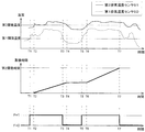
昇温制御部62は、(1)第1酸化触媒31に堆積したサルフェートの除去、(2)尿素水から生成された白色堆積物の除去、(3)エンジン10から排出されてSCR触媒41に堆積したHCの除去及び、(4)SCR触媒41に吸蔵されたNH3の除去により推定NH3吸蔵量と実NH3吸蔵量との誤差修正を目的とする昇温制御を実行する。本実施形態において、昇温制御は排気行程で所定量の燃料を噴射するポスト噴射によって第1酸化触媒31に未燃炭化水素(HC)を供給し、酸化反応熱で排気温度を昇温することで実現される。以下、昇温制御の詳細を図3のタイムチャートに基づいて説明する。
[開始条件]
昇温制御は、第1排気温度センサ50で検出される触媒入口温度が第1酸化触媒31の活性温度である所定の第1閾値温度以上、且つECU60内蔵のタイマが前回の昇温制御完了から所定の第1閾値時間を計時すると開始(パージフラグF:オン)される(図3の時刻T1参照)。第1閾値温度を開始条件としたのは、第1酸化触媒31が活性化しない低温状態で排気温度をサルフェートの脱離温度まで上昇させるには、ポスト噴射量が過多となる可能性があるためである。
昇温制御は、第1排気温度センサ50で検出される触媒入口温度が第1酸化触媒31の活性温度である所定の第1閾値温度以上、且つECU60内蔵のタイマが前回の昇温制御完了から所定の第1閾値時間を計時すると開始(パージフラグF:オン)される(図3の時刻T1参照)。第1閾値温度を開始条件としたのは、第1酸化触媒31が活性化しない低温状態で排気温度をサルフェートの脱離温度まで上昇させるには、ポスト噴射量が過多となる可能性があるためである。
[中断条件]
昇温制御の実行中に第1排気温度センサ50で検出される触媒入口温度が第1閾値温度よりも低下すると、昇温制御は中断(パージフラグF:オフ)される(図3の時刻T3参照)。第1閾値温度を中断条件としたのは、開始条件と同様にポスト噴射量の増加を回避するためである。なお、中断後に第1排気温度センサ50の検出値が第1閾値温度以上になると、昇温制御は再び開始(パージフラグF:オン)される(図3の時刻T5参照)。
昇温制御の実行中に第1排気温度センサ50で検出される触媒入口温度が第1閾値温度よりも低下すると、昇温制御は中断(パージフラグF:オフ)される(図3の時刻T3参照)。第1閾値温度を中断条件としたのは、開始条件と同様にポスト噴射量の増加を回避するためである。なお、中断後に第1排気温度センサ50の検出値が第1閾値温度以上になると、昇温制御は再び開始(パージフラグF:オン)される(図3の時刻T5参照)。
[終了条件]
昇温制御の実行中に第2排気温度センサ51が上述の(1)~(4)に記載したサルフェート、白色堆積物、HC、NH3を除去可能な所定の第2閾値温度以上を検出する時間を累積すると共に、当該累積時間が所定の第2閾値時間に達すると昇温制御は終了(パージフラグF:オフ)される。
昇温制御の実行中に第2排気温度センサ51が上述の(1)~(4)に記載したサルフェート、白色堆積物、HC、NH3を除去可能な所定の第2閾値温度以上を検出する時間を累積すると共に、当該累積時間が所定の第2閾値時間に達すると昇温制御は終了(パージフラグF:オフ)される。
より詳しくは、昇温制御の開始後、第2排気温度センサ52が第2閾値温度以上を検出すると、タイマによる時間の累積を開始する(図3の時刻T2参照)。その後、昇温制御の中断によってSCR触媒41の入口温度が第2閾値温度よりも低下すると、時間の累積を一時中断する(図3の時刻T4参照)。そして、SCR触媒41の入口温度が第2閾値温度以上になると、再び時間の累積を開始すると共に(図3の時刻T6)、累積時間が第2閾値時間に達すると、昇温制御を終了するようになっている(図3の時刻T7)。この第2閾値時間は、前回の昇温制御終了から今回の昇温制御開始までのインターバル間、すなわち前回の昇温制御終了から第1閾値時間が経過するまでに堆積したサルフェート等を確実に除去できる時間で設定される。
次に、本実施形態に係る排気浄化システムの作用効果を説明する。
本実施形態の排気浄化システムは、排気上流側から順にNO2を生成する第1酸化触媒31、未燃燃料や潤滑油等を主成分とするPM中のSOF成分を酸化浄化する第2酸化触媒32、NOxを還元浄化するSCR触媒41、NH3スリップを防止する第3酸化触媒42を配置して構成されている。さらに、エンジン10の燃料噴射は、マルチ噴射によりPM中の主にスート成分を低減させるPM低減噴射によって制御されるようになっている。すなわち、PM中のスート成分等をエンジン10の燃焼制御によって低減し、SOF成分を第2酸化触媒32で浄化することで、DPFを用いることなく排気エミッション性能を効果的に維持できるように構成されている。したがって、DPFを省略することが可能となり、装置の大型化やコスト上昇を効果的に抑制することができる。
また、DPFを省略したことで、ポスト噴射や排気管内噴射によるフィルタ強制再生を行う必要が無くなり、燃費性能を効果的に向上することができる。また、DPFの省略によって、アッシュを除去するDPFの定期的な掃除等が不要になり、メンテナンス性も効果的に向上することができる。
また、第1酸化触媒31に堆積するサルフェートや尿素水から生成される白色堆積物等は、昇温制御を定期的に行うことで効果的に除去されるようになっている。したがって、ポスト噴射で第1酸化触媒31に供給されたHCの第2酸化触媒32へのスリップ、白色堆積物による排気管腐食やSCR触媒41の性能劣化を効果的に防止することができる。
また、昇温制御は、第1酸化触媒31の入口温度が第1閾値温度以上の場合に開始され、さらに、第1酸化触媒31の入口温度が第1閾値温度よりも低下した場合は中断されるようになっている。したがって、ポスト噴射による燃料噴射量が過多になることを効果的に抑止することが可能となり、燃費の悪化を確実に防止することができる。
なお、本発明は、上述の実施形態に限定されるものではなく、本発明の趣旨を逸脱しない範囲で、適宜変形して実施することが可能である。
例えば、昇温制御はポスト噴射で行うものとして説明したが、第1酸化触媒31よりも上流側の排気通路16に燃料噴射装置を設け、パージ噴射を排気管内噴射で行うように構成してもよい。
Claims (6)
- 内燃機関の排気系に設けられて未燃炭化水素(HC)を酸化する第1酸化触媒と、
前記第1酸化触媒よりも下流側の排気系に設けられて尿素水から生成されるアンモニア(NH3)を還元剤として排気中の窒素化合物を還元浄化する選択的還元触媒と、
前記第1酸化触媒に未燃炭化水素(HC)を供給して排気温度を上昇させることで、少なくとも前記第1酸化触媒に堆積した硫酸成分(サルフェート)を除去する昇温制御を実行する昇温制御手段と、を備える
排気浄化システム。 - 前記第1酸化触媒に流入する排気温度を検出する第1温度検出手段をさらに備え、
前記昇温制御手段は、前記第1温度検出手段で検出される排気温度が前記第1酸化触媒の活性温度を示す所定の第1閾値温度以上の場合に昇温制御を開始する
請求項1に記載の排気浄化システム。 - 前記昇温制御手段は、昇温制御の実行中に前記第1温度検出手段で検出される排気温度が前記第1閾値温度よりも低下すると昇温制御を中断し、その後、前記第1温度検出手段で検出される排気温度が前記第1閾値温度以上になると昇温制御を再開する
請求項2に記載の排気浄化システム。 - 前記第1酸化触媒から流出する排気温度を検出する第2温度検出手段をさらに備え、
前記昇温制御手段は、昇温制御の開始から前記第2温度検出手段の検出値が前記硫酸成分を除去可能な所定の第2閾値温度以上となる時間を累積すると共に、当該累積時間が所定の閾値時間に達すると昇温制御を終了する
請求項2又は3に記載の排気浄化システム。 - 前記第1酸化触媒と前記選択的還元触媒との間の排気系に設けられて可溶性有機成分(SOF)を酸化する第2酸化触媒と、
前記内燃機関の燃料噴射を多段噴射で制御して前記内燃機関から排出される排気中のスート成分を低減させる燃焼制御手段と、をさらに備える
請求項1から4の何れか一項に記載の排気浄化システム。 - 前記選択的還元触媒よりも下流側の排気系に設けられて前記選択的還元触媒から脱離したアンモニア(NH3)を酸化する第3酸化触媒をさらに備える
請求項1から5の何れか一項に記載の排気浄化システム。
Applications Claiming Priority (2)
| Application Number | Priority Date | Filing Date | Title |
|---|---|---|---|
| JP2014143488A JP6398402B2 (ja) | 2014-07-11 | 2014-07-11 | 排気浄化システム |
| JP2014-143488 | 2014-07-11 |
Publications (1)
| Publication Number | Publication Date |
|---|---|
| WO2016006657A1 true WO2016006657A1 (ja) | 2016-01-14 |
Family
ID=55064285
Family Applications (1)
| Application Number | Title | Priority Date | Filing Date |
|---|---|---|---|
| PCT/JP2015/069768 Ceased WO2016006657A1 (ja) | 2014-07-11 | 2015-07-09 | 排気浄化システム |
Country Status (2)
| Country | Link |
|---|---|
| JP (1) | JP6398402B2 (ja) |
| WO (1) | WO2016006657A1 (ja) |
Cited By (2)
| Publication number | Priority date | Publication date | Assignee | Title |
|---|---|---|---|---|
| JP2017223180A (ja) * | 2016-06-16 | 2017-12-21 | 株式会社クボタ | ディーゼルエンジン |
| US12344762B2 (en) | 2020-12-31 | 2025-07-01 | Ppg Industries Ohio, Inc. | Phosphate resistant electrodepositable coating compositions |
Citations (9)
| Publication number | Priority date | Publication date | Assignee | Title |
|---|---|---|---|---|
| JPH0932619A (ja) * | 1995-07-14 | 1997-02-04 | Mitsubishi Motors Corp | 筒内噴射型内燃機関 |
| JPH11190209A (ja) * | 1997-10-22 | 1999-07-13 | Toyota Motor Corp | 内燃機関の排気浄化装置 |
| JP2002295244A (ja) * | 2001-03-28 | 2002-10-09 | Hino Motors Ltd | 排ガス浄化装置 |
| JP2005256632A (ja) * | 2004-03-09 | 2005-09-22 | Hiroshi Matsuoka | 排気ガス浄化システム |
| JP2005288362A (ja) * | 2004-04-01 | 2005-10-20 | Ne Chemcat Corp | ディーゼルエンジン排気ガス浄化装置 |
| JP2009041430A (ja) * | 2007-08-08 | 2009-02-26 | Isuzu Motors Ltd | NOx浄化方法及びNOx浄化システム |
| JP2010516948A (ja) * | 2007-01-31 | 2010-05-20 | ユミコア・アクチエンゲゼルシャフト・ウント・コムパニー・コマンディットゲゼルシャフト | リーンエンジンの排ガス装置内のすすフィルタを再生する方法及びこのための排ガス装置 |
| JP2012092675A (ja) * | 2010-10-25 | 2012-05-17 | Isuzu Motors Ltd | 内燃機関の制御装置 |
| JP2013002283A (ja) * | 2011-06-10 | 2013-01-07 | Hitachi Constr Mach Co Ltd | 排気浄化装置 |
Family Cites Families (1)
| Publication number | Priority date | Publication date | Assignee | Title |
|---|---|---|---|---|
| JP2005155574A (ja) * | 2003-11-28 | 2005-06-16 | Hino Motors Ltd | 排気浄化装置 |
-
2014
- 2014-07-11 JP JP2014143488A patent/JP6398402B2/ja not_active Expired - Fee Related
-
2015
- 2015-07-09 WO PCT/JP2015/069768 patent/WO2016006657A1/ja not_active Ceased
Patent Citations (9)
| Publication number | Priority date | Publication date | Assignee | Title |
|---|---|---|---|---|
| JPH0932619A (ja) * | 1995-07-14 | 1997-02-04 | Mitsubishi Motors Corp | 筒内噴射型内燃機関 |
| JPH11190209A (ja) * | 1997-10-22 | 1999-07-13 | Toyota Motor Corp | 内燃機関の排気浄化装置 |
| JP2002295244A (ja) * | 2001-03-28 | 2002-10-09 | Hino Motors Ltd | 排ガス浄化装置 |
| JP2005256632A (ja) * | 2004-03-09 | 2005-09-22 | Hiroshi Matsuoka | 排気ガス浄化システム |
| JP2005288362A (ja) * | 2004-04-01 | 2005-10-20 | Ne Chemcat Corp | ディーゼルエンジン排気ガス浄化装置 |
| JP2010516948A (ja) * | 2007-01-31 | 2010-05-20 | ユミコア・アクチエンゲゼルシャフト・ウント・コムパニー・コマンディットゲゼルシャフト | リーンエンジンの排ガス装置内のすすフィルタを再生する方法及びこのための排ガス装置 |
| JP2009041430A (ja) * | 2007-08-08 | 2009-02-26 | Isuzu Motors Ltd | NOx浄化方法及びNOx浄化システム |
| JP2012092675A (ja) * | 2010-10-25 | 2012-05-17 | Isuzu Motors Ltd | 内燃機関の制御装置 |
| JP2013002283A (ja) * | 2011-06-10 | 2013-01-07 | Hitachi Constr Mach Co Ltd | 排気浄化装置 |
Cited By (2)
| Publication number | Priority date | Publication date | Assignee | Title |
|---|---|---|---|---|
| JP2017223180A (ja) * | 2016-06-16 | 2017-12-21 | 株式会社クボタ | ディーゼルエンジン |
| US12344762B2 (en) | 2020-12-31 | 2025-07-01 | Ppg Industries Ohio, Inc. | Phosphate resistant electrodepositable coating compositions |
Also Published As
| Publication number | Publication date |
|---|---|
| JP6398402B2 (ja) | 2018-10-03 |
| JP2016020638A (ja) | 2016-02-04 |
Similar Documents
| Publication | Publication Date | Title |
|---|---|---|
| JP6135198B2 (ja) | 排ガス後処理装置の制御方法 | |
| JP4947036B2 (ja) | エンジンの排気浄化方法 | |
| JP4274270B2 (ja) | NOx浄化システム及びNOx浄化システムの制御方法 | |
| US9051859B2 (en) | Exhaust gas purification device and control method for exhaust gas purification device | |
| CN1981915A (zh) | 排气净化装置 | |
| JP2013142363A (ja) | ディーゼルエンジンの排気ガス浄化装置 | |
| JP4592504B2 (ja) | 排気浄化装置 | |
| JP5251711B2 (ja) | 内燃機関の排気浄化装置 | |
| CN109154223B (zh) | 内燃机的排气气体净化系统及内燃机的排气气体净化方法 | |
| JP5118331B2 (ja) | 排気浄化装置 | |
| JP5054607B2 (ja) | 排気浄化装置 | |
| JP2010180861A (ja) | 排気ガス浄化装置 | |
| CN104870763B (zh) | 内燃机的排气净化系统 | |
| JP2010053703A (ja) | 排気浄化装置 | |
| CN104870767A (zh) | 内燃机的排气净化系统 | |
| CN106661982A (zh) | 排气净化系统 | |
| JP6398402B2 (ja) | 排気浄化システム | |
| JP2010249076A (ja) | 内燃機関の排気浄化装置 | |
| CN104838100B (zh) | 内燃机的排气净化系统 | |
| JP2010196551A (ja) | 内燃機関の排気浄化装置 | |
| JP6398401B2 (ja) | 排気浄化システム | |
| JP2013092075A (ja) | 内燃機関の排気浄化装置 | |
| CN111788372A (zh) | 内燃机的排气气体净化系统及内燃机的排气气体净化方法 | |
| US10415448B2 (en) | Exhaust gas cleaning system for internal combustion engine and exhaust gas cleaning method for internal combustion engine | |
| JP2008128066A (ja) | 排気浄化装置 |
Legal Events
| Date | Code | Title | Description |
|---|---|---|---|
| 121 | Ep: the epo has been informed by wipo that ep was designated in this application |
Ref document number: 15819283 Country of ref document: EP Kind code of ref document: A1 |
|
| NENP | Non-entry into the national phase |
Ref country code: DE |
|
| 122 | Ep: pct application non-entry in european phase |
Ref document number: 15819283 Country of ref document: EP Kind code of ref document: A1 |