WO2016006635A1 - ガスセンサ素子 - Google Patents
ガスセンサ素子 Download PDFInfo
- Publication number
- WO2016006635A1 WO2016006635A1 PCT/JP2015/069694 JP2015069694W WO2016006635A1 WO 2016006635 A1 WO2016006635 A1 WO 2016006635A1 JP 2015069694 W JP2015069694 W JP 2015069694W WO 2016006635 A1 WO2016006635 A1 WO 2016006635A1
- Authority
- WO
- WIPO (PCT)
- Prior art keywords
- gas
- cell
- sensor
- measured
- gas inlet
- Prior art date
Links
Images


Classifications
-
- G—PHYSICS
- G01—MEASURING; TESTING
- G01N—INVESTIGATING OR ANALYSING MATERIALS BY DETERMINING THEIR CHEMICAL OR PHYSICAL PROPERTIES
- G01N27/00—Investigating or analysing materials by the use of electric, electrochemical, or magnetic means
- G01N27/26—Investigating or analysing materials by the use of electric, electrochemical, or magnetic means by investigating electrochemical variables; by using electrolysis or electrophoresis
- G01N27/403—Cells and electrode assemblies
- G01N27/406—Cells and probes with solid electrolytes
- G01N27/407—Cells and probes with solid electrolytes for investigating or analysing gases
- G01N27/41—Oxygen pumping cells
-
- G—PHYSICS
- G01—MEASURING; TESTING
- G01N—INVESTIGATING OR ANALYSING MATERIALS BY DETERMINING THEIR CHEMICAL OR PHYSICAL PROPERTIES
- G01N27/00—Investigating or analysing materials by the use of electric, electrochemical, or magnetic means
- G01N27/26—Investigating or analysing materials by the use of electric, electrochemical, or magnetic means by investigating electrochemical variables; by using electrolysis or electrophoresis
- G01N27/403—Cells and electrode assemblies
- G01N27/406—Cells and probes with solid electrolytes
- G01N27/407—Cells and probes with solid electrolytes for investigating or analysing gases
- G01N27/4071—Cells and probes with solid electrolytes for investigating or analysing gases using sensor elements of laminated structure
-
- G—PHYSICS
- G01—MEASURING; TESTING
- G01N—INVESTIGATING OR ANALYSING MATERIALS BY DETERMINING THEIR CHEMICAL OR PHYSICAL PROPERTIES
- G01N27/00—Investigating or analysing materials by the use of electric, electrochemical, or magnetic means
- G01N27/26—Investigating or analysing materials by the use of electric, electrochemical, or magnetic means by investigating electrochemical variables; by using electrolysis or electrophoresis
- G01N27/403—Cells and electrode assemblies
- G01N27/406—Cells and probes with solid electrolytes
- G01N27/407—Cells and probes with solid electrolytes for investigating or analysing gases
- G01N27/4073—Composition or fabrication of the solid electrolyte
- G01N27/4074—Composition or fabrication of the solid electrolyte for detection of gases other than oxygen
Definitions
- the present invention relates to a gas sensor element for detecting the concentration of a predetermined gas component contained in a gas to be measured.
- Some gas sensor elements for detecting the concentration of a predetermined gas component in the measurement gas include a pump cell that adjusts the oxygen concentration in the taken measurement gas. By adjusting the oxygen concentration in the gas to be measured by this pump cell, the detection accuracy in the sensor cell of the gas sensor element is prevented from deteriorating due to oxygen in the gas to be measured.
- Japanese Patent Application Laid-Open No. 8-271476 discloses a first internal space in which oxygen is discharged from a gas to be measured by a pump cell, and a second internal space in which the concentration of a predetermined gas component in the gas to be measured is detected by a sensor cell.
- a gas sensor element having a void is disclosed. The gas sensor element is provided between the first diffusion-controlled passage for diffusion-controlling the gas to be measured introduced into the first internal space, and the first internal space and the second internal space. And a second diffusion-controlled passage.
- the gas to be measured introduced from the outside passes through the first and second diffusion-controlled passages until reaching the second internal space where the sensor cell is provided, and the diffusion distance thereof. Will be longer. As a result, it becomes difficult to improve the responsiveness of the gas sensor element.
- the detection accuracy is deteriorated. That is, if the diffusion resistance of the first diffusion rate-limiting passage is reduced, a large amount of gas to be measured is introduced into the first internal space, making it difficult to sufficiently adjust the oxygen concentration in the gas to be measured. . Furthermore, if the diffusion resistance of the second diffusion-controlling passage is small, the gas to be measured is introduced into the second internal space without sufficiently adjusting the oxygen concentration in the first internal space, and the detection accuracy is improved. It will get worse.
- the present invention has been made in view of such a background, and intends to provide a gas sensor element capable of achieving both responsiveness and detection accuracy.
- a predetermined gas in a gas to be measured includes a first portion of a solid electrolyte body having oxygen ion conductivity and a pair of sensor electrodes provided on the solid electrolyte body.
- a sensor cell for detecting the concentration of the component includes a pump cell comprising a second portion of the solid electrolyte body and a pair of pump electrodes provided on the solid electrolyte body, and adjusting the oxygen concentration in the gas to be measured;
- a gas inlet configured to introduce the gas to be measured into the internal space and to give a predetermined diffusion resistance to the gas to be measured introduced into the internal space;
- the dimension of the gas inlet in the flow direction of the gas to be measured in the gas inlet is L1, the cross-sectional area of the gas inlet perpendicular to the flow direction of the gas to be measured in the gas inlet is S1, the gas inlet and the gas Gas sensor satisfying
- the gas sensor element can achieve both responsiveness and detection accuracy by satisfying 1000 ⁇ (L1 / S1) ⁇ (L2 / S2) ⁇ 5000.
- the inventors of the present application have focused on the fact that the responsiveness and detection accuracy greatly depend not only on the configuration of the gas inlet but also on the configuration of the internal space.
- (L1 / S1) is referred to as a first diffusion resistance index for convenience.
- the larger the first diffusion resistance index the slower the introduction rate of the gas to be measured into the internal space.
- the responsiveness is likely to decrease, but the detection accuracy is likely to be improved because the amount of oxygen to be adjusted by the pump cell tends to decrease.
- (L2 / S2) the diffusion resistance until the gas to be measured introduced into the internal space reaches the sensor electrode increases as this increases. Therefore, in this specification, (L2 / S2) is referred to as a second diffusion resistance index for convenience.
- the principle of influence on the responsiveness and the detection accuracy is slightly different between the first diffusion resistance index and the second diffusion resistance index, but as each index is larger, the responsiveness is more likely to decrease and the detection accuracy becomes higher.
- the inventors examined the relationship between the product of the first diffusion resistance index and the second diffusion resistance index, responsiveness, and detection accuracy (Experimental Examples 1 and 2 to be described later).
- the product of the first diffusion resistance index and the second diffusion resistance index that is, (L1 / S1) ⁇ (L2 / S2) is set to 1000 to 5000, thereby achieving both responsiveness and detection accuracy. I found out that it can be achieved.
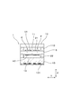
- FIG. 2 is a cross-sectional view taken along line II-II in FIG. 1.
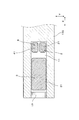
- FIG. 3 is a cross-sectional view taken along line III-III in FIG. 1.
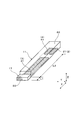
- FIG. 3 is a perspective explanatory view of an internal space and a gas inlet in the first embodiment.
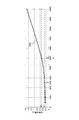
- the diagram which shows the relationship between the product P and the offset current in Experimental Example 1.
- the diagram which shows the relationship between the product P and the response time in Experimental example 2.
- the gas inlet may be composed of a porous body.
- the cross-sectional area S1 can be a value obtained by multiplying the cross-sectional area of the gas inlet by the porosity of the porous body.
- the diffusion resistance in the gas inlet can be easily adjusted, and the response and detection accuracy can be accurately managed by adjusting (L1 / S1) ⁇ (L2 / S2).
- the internal space preferably has a uniform shape from the region facing the pump electrode to the region facing the sensor electrode. In this case, since the gas to be measured introduced into the internal space can smoothly reach the sensor electrode, a gas sensor element with excellent responsiveness can be obtained.
- the cross sectional area S2 is defined as the cross sectional area S2.
- the gas inlet dimension L1 refers to the dimension of the gas inlet in the flow direction of the gas to be measured passing through the gas inlet.
- the cross-sectional area of the gas inlet perpendicular to the flow direction of the gas to be measured passing through the gas inlet differs depending on the flow direction of the gas to be measured
- the cross-sectional area of the portion having the smallest cross-sectional area is set as the cross-sectional area S1.
- the gas sensor element 1 of this example includes a solid electrolyte body 5 having oxygen ion conductivity, a sensor cell 2 for detecting the concentration of a specific gas in the gas to be measured, and a gas in the gas to be measured.
- a predetermined diffusion resistance is given to the pump cell 3 for adjusting the oxygen concentration, the internal space 11 into which the gas to be measured is introduced, and the gas to be measured that flows into the gas sensor element 1 (that is, the internal space 11) from the outside.
- the sensor cell 2 includes a part of the solid electrolyte body 5 having oxygen ion conductivity and a pair of sensor electrodes 21 and 22 provided on the solid electrolyte body 5.
- the pump cell 3 includes another part of the solid electrolyte body 5 and a pair of pump electrodes 31 and 32 provided on the solid electrolyte body 5, and is configured to adjust the oxygen concentration in the gas to be measured.
- the internal space 11 faces one sensor electrode 21 and one pump electrode 31 and is configured to introduce a gas to be measured.
- the gas inlet 17 is configured such that the gas to be measured passes and is introduced into the internal space 11, and functions as a diffusion resistor that imparts a predetermined diffusion resistance to the gas to be measured. .
- the dimension of the gas inlet 17 in the flow direction of the gas to be measured in the gas inlet 17 (in other words, the moving distance of the gas to be measured in the gas inlet 17) is L 1.
- the cross-sectional area of the gas inlet 17 perpendicular to the flow direction of the gas to be measured is S1
- the distance along the flow direction of the gas to be measured between the gas inlet 17 and the sensor cell 2 is L2
- the pump cell 3 and the sensor cell 2 Let S2 be the cross-sectional area of the internal space 11 orthogonal to the arrangement direction.
- L1, S1, L2, and S2 satisfy 1000 ⁇ (L1 / S1) ⁇ (L2 / S2) ⁇ 5000.
- the gas sensor element 1 of this example is a NOx sensor that detects a nitrogen oxide (NOx) concentration. That is, in this example, the gas to be measured is exhaust gas of an internal combustion engine such as an automobile, and the predetermined gas component is NOx.
- NOx nitrogen oxide
- the gas sensor element 1 includes a solid electrolyte body 5, a spacer 110 for forming the internal space 11, an insulating plate 12 facing the solid electrolyte body 5 through the internal space 11, A heater substrate 13 with a built-in heater 131 is laminated.
- the solid electrolyte body 5 is made of zirconia (ZrO 2 ), and the spacer 110, the insulating plate 12, and the heater substrate 13 are all made of alumina (Al 2 O 3 ).
- a reference gas chamber 14 into which air as a reference gas is introduced is formed between the heater substrate 13 and the solid electrolyte body 5, a reference gas chamber 14 into which air as a reference gas is introduced is formed. Further, as shown in FIGS. 1 and 3, a notch (recess) is provided in a part of the tip of the spacer 110, and the notch functions as a gas inlet 17. That is, the gas inlet 17 is formed at the tip of the gas sensor element 1.
- a porous body of alumina is arranged in the gas inlet 17 to give a predetermined diffusion resistance to the gas to be measured. That is, the gas inlet 17 is composed of a porous body of alumina. Therefore, the above-described cross-sectional area S1 is a value obtained by multiplying the cross-sectional area S0 (FIG. 4) of the gas inlet 17 (that is, the porous body) by the porosity of the porous body.
- the cross-sectional area S0 is a cross-sectional area of the porous body orthogonal to the flow direction of the gas to be measured flowing in the gas inlet 17.
- the porosity of the porous body can be measured, for example, by cutting the porous body to form a planar cross section and observing this with a SEM (Scanning Electron Microscope electron microscope) or the like. More specifically, the pores of the porous body are impregnated with a low-viscosity resin, and then cut with a slicer to expose a flat observation cross section. Next, after smoothing the observation cross section, the observation cross section is observed with an SEM. At this time, the area ratio of the aggregate appearing in the cross section is calculated by image processing, and a value obtained by subtracting this area ratio from 100% is calculated as the porosity.
- the gas inlet 17 is formed by a space (hole), and the size and shape of the space are given a predetermined diffusion resistance to the gas to be measured flowing into the internal space 11. You may form in.
- the internal space 11 has a uniform shape from the region where the pump electrode 31 faces to the region where the sensor electrode 21 faces.
- the internal space 11 has a rectangular parallelepiped shape, and has a rectangular shape having substantially the same cross-sectional shape perpendicular to the axial direction X from the distal end to the proximal end.
- the solid electrolyte body 5 has two main surfaces facing each other.
- a pump electrode 31 and a sensor electrode 21 formed on one of the two main surfaces of the solid electrolyte body 5 are disposed in the internal space 11.
- the reference gas chamber 14 is provided with a pump electrode 32 and a sensor electrode 22 formed on the other main surface of the solid electrolyte body 5.
- the pump electrode 32 and the sensor electrode 22 constitute an integrated common electrode.
- the gas sensor element 1 has a monitor cell 4 for detecting the oxygen concentration in the exhaust gas (measured gas).
- the monitor cell 4 includes a part of the solid electrolyte body 5 and a pair of monitoring electrodes 41 and 42 provided on the solid electrolyte body 5. That is, in addition to the pump electrode 31 and the sensor electrode 21, the monitor electrode 41 is also arranged in the internal space 11, and in addition to the pump electrode 32 and the sensor electrode 22, the reference gas chamber 14 is arranged. A monitoring electrode 42 is also disposed. However, the monitor electrode 42 constitutes one common electrode together with the pump electrode 32 and the sensor electrode 22.
- the arrangement direction of the sensor cell 2 and the monitor cell 4 is orthogonal to the arrangement direction of the pump cell 3 and the sensor cell 2.
- the arrangement direction of the pump cell 3 and the sensor cell 2 is the axial direction X of the gas sensor element 1
- the arrangement direction of the sensor cell 2 and the monitor cell 4 is both the axial direction X and the stacking direction Z in the gas sensor element 1.
- the sensor cell 2 and the monitor cell 4 are arranged on the proximal end side with respect to the pump cell 3. That is, the sensor cell 2 and the monitor cell 4 are located on the opposite side of the gas inlet 17 with the pump cell 3 in between in the axial direction X.
- the positions of the sensor cell 2, the pump cell 3, and the monitor cell 4 coincide with the positions of the sensor electrode 21, the pump electrode 31, and the monitor electrode 41, respectively.
- the sensor electrode 21, the monitor electrode 41, and the pump electrode 31 facing the internal space 11 are each made of an alloy containing two or more metal components. More specifically, the sensor electrode 21 is an alloy of Pt (platinum) and Rh (rhodium), and the monitor electrode 41 and the pump electrode 31 are an alloy of Pt and Au (gold). Thereby, the sensor electrode 21 can decompose NOx molecules and oxygen molecules, and the monitor electrode 41 and the pump electrode 31 decompose oxygen molecules, but NOx molecules do not decompose.
- the gas to be measured passes through the gas inlet 17 and is introduced into the internal space 11.
- oxygen in the exhaust gas is reduced to oxygen ions on the pump electrode 31 on the inner space 11 side, and the other is pumped.
- oxygen is discharged from the internal space 11 to the reference gas chamber 14.
- a predetermined voltage is applied to the pair of sensor electrodes 21 and 22 of the sensor cell 2.
- oxygen and nitrogen oxides in the exhaust gas in the internal space 11 are decomposed on the sensor electrode 21, and oxygen ions are sent to the other sensor electrode 22 by a pumping action.
- the current flowing through the sensor cell 2 results from the concentration of nitrogen oxides and the concentration of oxygen.
- the current values of the sensor cell 2 and the monitor cell 4 are measured while the oxygen concentration in the internal space 11 is maintained at a predetermined value by the pump cell 3.
- the concentration of nitrogen oxide can be accurately calculated from the difference between the current value measured in the sensor cell 2 and the current value measured in the monitor cell 4.
- the gas sensor element 1 can achieve both responsiveness and detection accuracy by satisfying 1000 ⁇ (L1 / S1) ⁇ (L2 / S2) ⁇ 5000.
- the inventors of the present application pay attention to the fact that the responsiveness and detection accuracy greatly depend not only on the configuration of the gas inlet 17 but also on the configuration of the internal space 11, and as shown in Experimental Examples 1 and 2 described later, The relationship between the product P of the 1 diffusion resistance index (L1 / S1) and the second diffusion resistance index (L2 / S2), and the responsiveness and detection accuracy was examined.
- the product of the first diffusion resistance index and the second diffusion resistance index that is, (L1 / S1) ⁇ (L2 / S2) is set to 1000 to 5000, thereby achieving both responsiveness and detection accuracy. I found out that it can be achieved. Furthermore, it has been found that by setting (L1 / S1) ⁇ (L2 / S2) to 1250 to 2500, both responsiveness and detection accuracy can be more effectively achieved.
- the gas inlet 17 is formed of a porous body as described above, and the cross-sectional area S1 is a value obtained by multiplying the cross-sectional area S0 of the gas inlet 17 by the porosity of the porous body. .
- the diffusion resistance in the gas inlet 17 can be easily adjusted, and the response and detection accuracy can be accurately managed by adjusting (L1 / S1) ⁇ (L2 / S2).
- the internal space 11 has a uniform shape from the region facing the pump electrode 31 to the region facing the sensor electrode 21. Thereby, since the gas to be measured (exhaust gas) introduced into the internal space 11 can smoothly reach the sensor electrode 21, the gas sensor element 1 having excellent responsiveness can be obtained.
- the gas sensor element 1 has the monitor cell 4, it is possible to improve the detection accuracy of a predetermined gas component concentration (NOx concentration). Moreover, since the alignment direction of the sensor cell 2 and the monitor cell 4 is orthogonal to the alignment direction of the pump cell 3 and the sensor cell 2, the detection accuracy can be further improved.
- Example 1 In this example, as shown in FIG. 5, the relationship between the product P of the first diffusion resistance index (L1 / S1) and the second diffusion resistance index (L2 / S2) and the detection accuracy of the gas sensor element was examined. That is, the detection accuracy was evaluated by the value of the offset current flowing through the sensor cell 2.
- the offset current is a current that flows through the sensor cell 2 even when NOx gas as the specific gas does not exist in the gas to be measured, and the detection accuracy is likely to deteriorate as the value increases.
- the gas sensor element used in the experiment a plurality of elements having various shapes changed so that the value of the product P is changed while the basic structure shown in Example 1 was used. Specifically, the product P was changed by variously changing the distance L2 and the cross-sectional area S2 from the base end of the gas inlet 17 to the tip of the sensor cell 2 in the internal space 11.
- the offset current was measured for each gas sensor element. That is, a gas sensor incorporating each gas sensor element was produced and installed in an exhaust pipe through which the gas to be measured flows.
- the gas to be measured used here is a gas not containing NOx and containing 20% oxygen.
- the measurement results are shown in FIG. In the figure, five plots shown in the graph are measured values, and a curve M1 is an approximate curve along the measured values.
- the offset current decreases as the product P increases.
- P ⁇ 1000 the offset current is 0.1 ⁇ A or less
- P ⁇ 1250 the offset current is 0.05 ⁇ A or less. From this result, it is understood that by increasing the product P, the offset current can be reduced and the detection accuracy of the gas sensor element is improved.
- P ⁇ 1000 the detection accuracy of the gas sensor element can be sufficiently secured, and by setting P ⁇ 1250, the detection accuracy of the gas sensor element can be further improved.
- Example 2 In this example, as shown in FIG. 6, the relationship between the product P of the first diffusion resistance index (L1 / S1) and the second diffusion resistance index (L2 / S2) and the responsiveness of the gas sensor element was examined. Evaluation of responsiveness was performed by measuring the response time of each gas sensor element with respect to nitrogen oxides. As the gas sensor element used in the experiment, a plurality of elements having various shapes changed so that the value of the product P is changed while the basic structure shown in the first embodiment is used.
- the response time was measured for each gas sensor element. That is, a gas sensor incorporating each gas sensor element was produced and installed in an exhaust pipe through which the gas to be measured flows at a flow rate of 12 m / s. While measuring the sensor output in this state, the NOx concentration of the gas to be measured was suddenly changed at a certain time. The time from when the NOx concentration was changed until the sensor output was changed was defined as the response time.
- the measurement results are shown in FIG. In the figure, five plots shown in the graph are measured values, and a curve M2 is an approximate curve along the measured values.
- the response time decreases as the product P decreases.
- P ⁇ 5000 the response time is 0.5 seconds or less
- P ⁇ 2500 the response time is 0.3 seconds or less. From this result, it can be seen that by reducing the product P, the response time can be shortened and the detection accuracy of the gas sensor element is improved.
- P ⁇ 5000 the response time of the gas sensor element can be sufficiently shortened, and by setting P ⁇ 2500, the response time of the gas sensor element can be further shortened.
- the gas sensor element 1 of the present invention can take various configurations in addition to the above embodiments.
- the gas inlet 17 is formed of a porous body has been described.
- the porous body may not be disposed there.
- the gas inlet 17 was shown in the example which has been arrange
- the dimension L1 is the dimension of the gas inlet 17 in the stacking direction Z (thickness direction) and the width direction Y, respectively. That is, the dimension L1 is the dimension of the gas inlet 17 along the gas flow direction.
Abstract
ガスセンサ素子1は、センサセル2と、ポンプセル3と、内部空間11と、ガスインレット17と、を備える。センサセル2は、固体電解質体5の一部と、固体電解質体5に設けられた一対のセンサ用電極21、22とからなる。ポンプセル3は、固体電解質体5の他の一部と、固体電解質体5に設けられた一対のポンプ用電極31、32とからなる。内部空間11は、一方のセンサ用電極21及び一方のポンプ用電極31に面する。前記ガスインレット(17)内の被測定ガスの流れ方向における、前記ガスインレット(17)の寸法をL1、ガスインレット(17)内の被測定ガスの流れ方向に直交する前記ガスインレット(17)の断面積をS1、ガスインレット(17)とセンサセル(2)との間の距離をL2、上記ポンプセル(3)と上記センサセル(2)との並び方向に直交する前記内部空間(11)の断面積をS2としたとき、1000≦(L1/S1)×(L2/S2)≦5000を満たす。
Description
本発明は、被測定ガス中に含まれる所定のガス成分の濃度を検出するためのガスセンサ素子に関する。
被測定ガス中の所定のガス成分の濃度を検出するためのガスセンサ素子として、取り込んだ被測定ガス中の酸素濃度を調整するポンプセルを備えたものがある。このポンプセルによって被測定ガス中の酸素濃度を調整することにより、ガスセンサ素子のセンサセルにおける検出精度が、被測定ガス中の酸素に起因して悪化することを防いでいる。
そして、特開平8-271476号公報には、ポンプセルによって被測定ガスから酸素を排出させる第一の内部空所と、センサセルによって被測定ガス中の所定のガス成分の濃度を検出する第二の内部空所とを有するガスセンサ素子が開示されている。そして、このガスセンサ素子は、第一の内部空所に導入する被測定ガスを拡散律速する第一の拡散律速通路と、第一の内部空所と第二の内部空所との間に設けた第二の拡散律速通路とを有する。
しかしながら、上記構成によると、外部から導入される被測定ガスは、センサセルが設けられた第二の内部空所に達するまでに、第一及び第二の拡散律速通路を通ることとなり、その拡散距離が長くなることとなる。その結果、ガスセンサ素子の応答性を向上させることが困難となる。
また、応答性を向上させるべく、拡散律速通路の拡散抵抗を小さくすることも考えられるが、その場合、検出精度が悪化することとなる。つまり、第一の拡散律速通路の拡散抵抗を小さくすると、第一の内部空所に被測定ガスが多く導入されることとなり、被測定ガス中の酸素濃度を充分に調整することが困難となる。さらに、第二の拡散律速通路の拡散抵抗が小さいと、第一の内部空所において充分に酸素濃度が調整されないまま、被測定ガスが第二の内部空所に導入されてしまい、検出精度が悪化することとなる。
本発明は、かかる背景に鑑みてなされたものであり、応答性と検出精度との両立を図ることができるガスセンサ素子を提供しようとするものである。
本発明の一態様によれば、酸素イオン伝導性を有する固体電解質体の第1の部分と、該固体電解質体に設けられた一対のセンサ用電極とからなり、被測定ガス中の所定のガス成分の濃度を検出するセンサセルと、
上記固体電解質体の第2の部分と、該固体電解質体に設けられた一対のポンプ用電極とからなり、上記被測定ガス中の酸素濃度を調整するポンプセルと、
一方の上記センサ用電極及び一方の上記ポンプ用電極に面するとともに、上記被測定ガスが導入される内部空間と、
前記内部空間に上記被測定ガスを導入するとともに、前記内部空間に導入される上記被測定ガスに対して所定の拡散抵抗を付与するように形成されたガスインレットと、を備え、
前記ガスインレット内の被測定ガスの流れ方向における、前記ガスインレットの寸法をL1、前記ガスインレット内の被測定ガスの流れ方向に直交する、前記ガスインレットの断面積をS1、上記ガスインレットと上記センサセルとの間の距離をL2、上記ポンプセルと上記センサセルとの並び方向に直交する前記内部空間の断面をS2としたとき、1000≦(L1/S1)×(L2/S2)≦5000を満たすガスセンサ素子が提供される。
上記ガスセンサ素子は、1000≦(L1/S1)×(L2/S2)≦5000を満たすことにより、応答性と検出精度との両立を図ることができる。
本願発明者らは、応答性及び検出精度が、ガスインレットの構成のみならず、内部空間の構成にも大きく依存することに着目した。まず、(L1/S1)が大きいほど、ガスインレットにおける拡散抵抗は大きくなる。そこで、本明細書においては、(L1/S1)を便宜的に第1拡散抵抗指標という。この第1拡散抵抗指標が大きいほど、内部空間への被測定ガスの導入速度は遅くなりやすい。その結果、応答性は低下しやすいが、ポンプセルによって調整すべき酸素の量が少なくなりやすい分、検出精度は向上しやすい。
本願発明者らは、応答性及び検出精度が、ガスインレットの構成のみならず、内部空間の構成にも大きく依存することに着目した。まず、(L1/S1)が大きいほど、ガスインレットにおける拡散抵抗は大きくなる。そこで、本明細書においては、(L1/S1)を便宜的に第1拡散抵抗指標という。この第1拡散抵抗指標が大きいほど、内部空間への被測定ガスの導入速度は遅くなりやすい。その結果、応答性は低下しやすいが、ポンプセルによって調整すべき酸素の量が少なくなりやすい分、検出精度は向上しやすい。
そして、(L2/S2)についても、これが大きいほど、内部空間に導入された被測定ガスがセンサ用電極に到達するまでの拡散抵抗は大きくなる。そこで、本明細書においては、(L2/S2)を便宜的に第2拡散抵抗指標という。この第2拡散抵抗指標が大きいほど、内部空間に導入された被測定ガスがセンサ用電極に達するまでの時間は長くなる。その結果、応答性は低下しやすいが、ポンプセルによって酸素を調整する時間が稼げる分、検出精度は向上しやすい。
このように、第1拡散抵抗指標及び第2拡散抵抗指標は、応答性及び検出精度に及ぼす影響の原理が若干異なるが、各指標が大きいほど、応答性が低下しやすく、検出精度が高くなる点においては共通する。そこで、発明者らは、第1拡散抵抗指標と第2拡散抵抗指標との積と、応答性及び検出精度との関係を調べた(後述する実験例1、2)。その結果、第1拡散抵抗指標と第2拡散抵抗指標との積、すなわち(L1/S1)×(L2/S2)を、1000~5000とすることにより、応答性と検出精度との両立を効果的に図ることができることを見出した。
以上のごとく、本発明によれば、応答性と検出精度との両立を図ることができるガスセンサ素子を提供することができる。
上記ガスセンサ素子において、1250≦(L1/S1)×(L2/S2)≦2500を満たすことが好ましい。この場合には、応答性と検出精度との両立を一層効果的に図ることができる。
なお、本明細書において、第1拡散抵抗指標と第2拡散抵抗指標との積を、適宜Pとも表す。すなわち、(L1/S1)×(L2/S2)=Pである。
なお、本明細書において、第1拡散抵抗指標と第2拡散抵抗指標との積を、適宜Pとも表す。すなわち、(L1/S1)×(L2/S2)=Pである。
また、上記ガスインレットは、多孔質体によって構成してもよい。この場合には、上記断面積S1は、上記ガスインレットの断面積に上記多孔質体の気孔率を乗じた値であることとすることができる。この場合には、ガスインレットにおける拡散抵抗を容易に調整することができるとともに、(L1/S1)×(L2/S2)の調整によって、応答性及び検出精度を正確に管理することができる。
また、上記内部空間は、上記ポンプ用電極が面する領域から上記センサ用電極が面する領域に至るまで、一様な形状を有することが好ましい。この場合には、内部空間に導入された被測定ガスが円滑にセンサ用電極まで到達することができるため、応答性に優れたガスセンサ素子を得ることができる。
なお、内部空間におけるポンプセルとセンサセルとの並び方向に直交する断面の断面積が、ポンプセルとセンサセルとの並び方向における位置によって異なる場合には、ガスインレットとセンサセルとの間において最も断面積が小さい部分の断面積を、上記断面積S2とする。また、ガスインレットの寸法L1とは、ガスインレット内を通る被測定ガスの流れ方向におけるガスインレットの寸法をいう。また、ガスインレット内を通る被測定ガスの流れ方向に直交するガスインレットの断面積が、被測定ガスの流れ方向よって異なる場合には、最も断面積が小さい部分の断面積を、上記断面積S1とする。
(実施例1)
上記ガスセンサ素子の実施例につき、図1~図4を用いて説明する。
本例のガスセンサ素子1は、図1、図2に示すごとく、酸素イオン伝導性を有する固体電解質体5と、被測定ガス中の特定ガスの濃度を検出するセンサセル2と、被測定ガス中の酸素濃度を調整するポンプセル3と、被測定ガスが導入される内部空間11と、ガスセンサ素子1(すなわち、内部空間11)に外部より流入する被測定ガスに対して所定の拡散抵抗を付与するように形成されたガスインレット17と、を備えている。
上記ガスセンサ素子の実施例につき、図1~図4を用いて説明する。
本例のガスセンサ素子1は、図1、図2に示すごとく、酸素イオン伝導性を有する固体電解質体5と、被測定ガス中の特定ガスの濃度を検出するセンサセル2と、被測定ガス中の酸素濃度を調整するポンプセル3と、被測定ガスが導入される内部空間11と、ガスセンサ素子1(すなわち、内部空間11)に外部より流入する被測定ガスに対して所定の拡散抵抗を付与するように形成されたガスインレット17と、を備えている。
センサセル2は、酸素イオン伝導性を有する固体電解質体5の一部と、該固体電解質体5に設けられた一対のセンサ用電極21、22とからなる。
ポンプセル3は、固体電解質体5の他の一部と、該固体電解質体5に設けられた一対のポンプ用電極31、32とからなり、被測定ガス中の酸素濃度を調整するよう構成されている。
内部空間11は、一方のセンサ用電極21及び一方のポンプ用電極31に面するとともに、被測定ガスが導入されるよう構成されている。
ガスインレット17は、上記したように、被測定ガスが通過し、内部空間11に導入されるように構成されており、被測定ガスに対して所定の拡散抵抗を付与する拡散抵抗体として機能する。
ポンプセル3は、固体電解質体5の他の一部と、該固体電解質体5に設けられた一対のポンプ用電極31、32とからなり、被測定ガス中の酸素濃度を調整するよう構成されている。
内部空間11は、一方のセンサ用電極21及び一方のポンプ用電極31に面するとともに、被測定ガスが導入されるよう構成されている。
ガスインレット17は、上記したように、被測定ガスが通過し、内部空間11に導入されるように構成されており、被測定ガスに対して所定の拡散抵抗を付与する拡散抵抗体として機能する。
図1、図4に示すごとく、ガスインレット17内の被測定ガスの流れ方向における、ガスインレット17の寸法(言い換えれば、ガスインレット17内の被測定ガスの移動距離)をL1、ガスインレット17内の被測定ガスの流れ方向に直交する、ガスインレット17の断面積をS1、ガスインレット17とセンサセル2との間の被測定ガスの流れ方向に沿った距離をL2、ポンプセル3とセンサセル2との並び方向に直交する内部空間11の断面積をS2とする。このとき、L1、S1、L2、S2は、1000≦(L1/S1)×(L2/S2)≦5000を満たす。また、1250≦(L1/S1)×(L2/S2)≦2500を満たすことが好ましい。
本例のガスセンサ素子1は、窒素酸化物(NOx)濃度を検出するNOxセンサである。すなわち、本例においては、被測定ガスは、自動車等の内燃機関の排ガスであり、所定ガス成分はNOxである。
図1、図2に示すごとく、ガスセンサ素子1は、固体電解質体5と、内部空間11を形成するためのスペーサ110と、内部空間11を介して固体電解質体5と対向する絶縁板12と、ヒータ131を内蔵したヒータ基板13とを積層してなる。固体電解質体5はジルコニア(ZrO2)からなり、スペーサ110、絶縁板12、ヒータ基板13は、いずれもアルミナ(Al2O3)からなる。
ヒータ基板13と固体電解質体5との間には、基準ガスである空気が導入される基準ガス室14が形成されている。また、図1、図3に示すごとく、スペーサ110の先端部の一部に切欠き(くぼみ)が設けられており、該切欠きがガスインレット17として機能する。つまり、ガスインレット17は、ガスセンサ素子1の先端部に形成されている。
本例において、ガスインレット17には、アルミナの多孔質体が配置されて所定の拡散抵抗を被測定ガスに対して付与している。つまり、ガスインレット17はアルミナの多孔質体により構成されている。それゆえ、上述の断面積S1は、ガスインレット17(すなわち多孔質体)の断面積S0(図4)に多孔質体の気孔率を乗じた値である。ここで、断面積S0は、ガスインレット17内を流れる被測定ガスの流れ方向に直交する多孔質体の断面積である。また、多孔質体の気孔率は、例えば、多孔質体を切断して平面な断面を形成し、これをSEM(Scanning Electron Microscope電子顕微鏡)等にて観察することにより、測定することができる。より具体的には、多孔質体の気孔に低粘度の樹脂を含浸させたのち、スライサーにより切断し、平面な観察断面を露出させる。次いで、観察断面を平滑化した後、観察断面をSEMにて観察する。このとき、断面に現れている骨材(aggregate)の面積割合を画像処理にて計算して、この面積割合を100%から引いた値が、気孔率として算出される。なお、ガスインレット17に多孔質体を設けることなく、ガスインレット17を空間(孔)により形成し、その空間のサイズや形状を所定の拡散抵抗を内部空間11に流入する被測定ガスに与えるように形成してもよい。
また、図4に示すごとく、内部空間11は、ポンプ用電極31が面する領域からセンサ用電極21が面する領域に至るまで、一様な形状を有する。本例においては、特に、内部空間11は直方体形状を有し、その先端から基端に至るまで、軸方向Xに直交する断面の形状が略同一の長方形状を有する。
図1、図3に示すごとく、固体電解質体5は互いに対向する二つの主面を有している。内部空間11には、固体電解質体5の二つの主面の一方に形成されたポンプ用電極31とセンサ用電極21とが配されている。また、基準ガス室14には、固体電解質体5の他方の主面に形成されたポンプ用電極32とセンサ用電極22とが配されている。ただし、本例においては、ポンプ用電極32とセンサ用電極22とは、一体化された一つの共通電極を構成している。
さらに、ガスセンサ素子1は、図2、図3に示すごとく、排ガス(被測定ガス)中の酸素濃度を検出するモニタセル4を有している。モニタセル4は、固体電解質体5の一部と固体電解質体5に設けられた一対のモニタ用電極41、42とからなる。つまり、内部空間11には、ポンプ用電極31及びセンサ用電極21の他に、モニタ用電極41も配されており、基準ガス室14には、ポンプ用電極32及びセンサ用電極22の他に、モニタ用電極42も配されている。ただし、モニタ用電極42は、ポンプ用電極32及びセンサ用電極22とともに、一体化された一つの共通電極を構成している。
図3に示すごとく、センサセル2とモニタセル4との並び方向は、ポンプセル3とセンサセル2との並び方向に直交する。本例においては、ポンプセル3とセンサセル2との並び方向は、ガスセンサ素子1の軸方向Xであり、センサセル2とモニタセル4との並び方向は、ガスセンサ素子1における軸方向X及び積層方向Zの双方に直交する幅方向Yである。また、センサセル2及びモニタセル4は、ポンプセル3よりも基端側に配されている。つまり、センサセル2及びモニタセル4は、軸方向Xにおいて、ポンプセル3を挟んでガスインレット17と反対側に位置する。センサセル2、ポンプセル3、モニタセル4の位置は、それぞれセンサ用電極21、ポンプ用電極31、モニタ用電極41の位置と一致する。
本例において、内部空間11に面するセンサ用電極21とモニタ用電極41とポンプ用電極31とは、それぞれ2種以上の金属成分を含有する合金からなる。より具体的には、センサ用電極21はPt(白金)とRh(ロジウム)の合金であり、モニタ用電極41及びポンプ用電極31はPtとAu(金)の合金である。これにより、センサ用電極21は、NOx分子及び酸素分子を分解することができ、モニタ用電極41及びポンプ用電極31は、酸素分子を分解するものの、NOx分子は分解しない。
次に、ガスセンサ素子1の動作につき説明する。
まず、被測定ガスは、ガスインレット17を通過して、内部空間11に導入される。この状態において、ポンプセル3の一対のポンプ用電極31、32に電圧を印加することにより、内部空間11側のポンプ用電極31上において排ガス中の酸素が還元されて酸素イオンとなり、ポンピング作用により他方のポンプ用電極32へ送られる。これにより、酸素が内部空間11から基準ガス室14に排出される。
まず、被測定ガスは、ガスインレット17を通過して、内部空間11に導入される。この状態において、ポンプセル3の一対のポンプ用電極31、32に電圧を印加することにより、内部空間11側のポンプ用電極31上において排ガス中の酸素が還元されて酸素イオンとなり、ポンピング作用により他方のポンプ用電極32へ送られる。これにより、酸素が内部空間11から基準ガス室14に排出される。
また、モニタセル4の一対のモニタ用電極41、42に所定の電圧を印加すると、内部空間11側のモニタ用電極41上において排ガス中の酸素が還元されて酸素イオンとなり、ポンピング作用により他方のモニタ用電極42に送られる。このときモニタセル4に流れた電流は、被測定ガス中の酸素濃度に起因する。
また、センサセル2の一対のセンサ用電極21、22に所定の電圧を印加する。これにより、センサ用電極21上において内部空間11の排ガス中の酸素及び窒素酸化物が分解され、酸素イオンがポンピング作用により他方のセンサ用電極22に送られる。このときセンサセル2に流れる電流は、窒素酸化物の濃度と酸素の濃度とに起因する。
このようにして、ポンプセル3によって内部空間11における酸素濃度を所定の値に保ちつつ、センサセル2及びモニタセル4にそれぞれ流れる電流値を測定する。これにより、センサセル2において測定された電流値とモニタセル4において測定された電流値との差分から、窒素酸化物の濃度を正確に算出することが可能となる。
次に、本例の作用効果につき説明する。
ガスセンサ素子1は、1000≦(L1/S1)×(L2/S2)≦5000を満たすことにより、応答性と検出精度との両立を図ることができる。
本願発明者らは、応答性及び検出精度が、ガスインレット17の構成のみならず、内部空間11の構成にも大きく依存することに着目し、後述する実験例1、2に示すように、第1拡散抵抗指標(L1/S1)と第2拡散抵抗指標(L2/S2)との積Pと、応答性及び検出精度との関係を調べた。その結果、第1拡散抵抗指標と第2拡散抵抗指標との積、すなわち(L1/S1)×(L2/S2)を、1000~5000とすることにより、応答性と検出精度との両立を効果的に図ることができることを見出した。さらには、(L1/S1)×(L2/S2)を、1250~2500とすることにより、応答性と検出精度との両立を一層効果的に図ることができることを見出した。
また、本実施例では、ガスインレット17は、上記したように多孔質体によって構成されており、断面積S1は、ガスインレット17の断面積S0に多孔質体の気孔率を乗じた値とした。これにより、ガスインレット17における拡散抵抗の調整が容易になるとともに、(L1/S1)×(L2/S2)の調整によって、応答性及び検出精度を正確に管理することができる。
また、内部空間11は、ポンプ用電極31が面する領域からセンサ用電極21が面する領域に至るまで、一様な形状を有する。これにより、内部空間11に導入された被測定ガス(排ガス)が円滑にセンサ用電極21まで到達することができるため、応答性に優れたガスセンサ素子1を得ることができる。
また、ガスセンサ素子1は、モニタセル4を有しているため、所定のガス成分の濃度(NOx濃度)の検出精度を向上させることができる。また、センサセル2とモニタセル4との並び方向は、ポンプセル3とセンサセル2との並び方向に直交するため、一層検出精度の向上を図ることができる。
以上のごとく、本例によれば、応答性と検出精度との両立を図ることができるガスセンサ素子を提供することができる。
(実験例1)
本例においては、図5に示すごとく、第1拡散抵抗指標(L1/S1)と第2拡散抵抗指標(L2/S2)との積Pと、ガスセンサ素子の検出精度との関係を調べた。
すなわち、検出精度を、センサセル2に流れるオフセット電流の値によって評価した。オフセット電流は、被測定ガス中に特定ガスとしてのNOxガスが存在しないときにもセンサセル2に流れる電流であり、これが大きいほど検出精度が悪化しやすい。
本例においては、図5に示すごとく、第1拡散抵抗指標(L1/S1)と第2拡散抵抗指標(L2/S2)との積Pと、ガスセンサ素子の検出精度との関係を調べた。
すなわち、検出精度を、センサセル2に流れるオフセット電流の値によって評価した。オフセット電流は、被測定ガス中に特定ガスとしてのNOxガスが存在しないときにもセンサセル2に流れる電流であり、これが大きいほど検出精度が悪化しやすい。
実験に用いるガスセンサ素子としては、実施例1において示したものを基本構成としつつ、上記積Pの値が変化するように、各部の形状を種々変化させたものを複数個用意した。具体的には、内部空間11におけるガスインレット17の基端からセンサセル2の先端までの距離L2及び断面積S2を種々変化させることにより、上記積Pを変化させた。
そして、各ガスセンサ素子について、オフセット電流を測定した。つまり、各ガスセンサ素子を内蔵したガスセンサを作製し、これを被測定ガスが流れる排気管に設置した。ここで用いた被測定ガスは、NOxを含まず、酸素を20%含むガスである。
測定結果を図5に示す。同図において、グラフ中に示した5個のプロットが測定値であり、曲線M1は上記測定値に沿った近似曲線である。同図から分かるように、積Pが大きくなるほど、オフセット電流が小さくなる。そして、P≧1000においては、オフセット電流が0.1μA以下となり、さらに、P≧1250においては、オフセット電流が0.05μA以下となる。この結果から、積Pを大きくすることにより、オフセット電流を小さくすることができ、ガスセンサ素子の検出精度が向上することが分かる。そして、P≧1000とすることにより、ガスセンサ素子の検出精度を充分に確保することができ、P≧1250とすることにより、ガスセンサ素子の検出精度をより向上させることができる。
(実験例2)
本例においては、図6に示すごとく、第1拡散抵抗指標(L1/S1)と第2拡散抵抗指標(L2/S2)との積Pと、ガスセンサ素子の応答性との関係を調べた。
応答性の評価は、窒素酸化物に対する各ガスセンサ素子の応答時間を測定することにより行った。実験に用いるガスセンサ素子としては、実施例1において示したものを基本構成としつつ、上記積Pの値が変化するように、各部の形状を種々変化させたものを複数個用意した。
本例においては、図6に示すごとく、第1拡散抵抗指標(L1/S1)と第2拡散抵抗指標(L2/S2)との積Pと、ガスセンサ素子の応答性との関係を調べた。
応答性の評価は、窒素酸化物に対する各ガスセンサ素子の応答時間を測定することにより行った。実験に用いるガスセンサ素子としては、実施例1において示したものを基本構成としつつ、上記積Pの値が変化するように、各部の形状を種々変化させたものを複数個用意した。
そして、各ガスセンサ素子について、応答時間を測定した。つまり、各ガスセンサ素子を内蔵したガスセンサを作製し、これを流速12m/sにて被測定ガスが流れる排気管に設置した。この状態においてセンサ出力を計測しつつ、ある時点において急激に被測定ガスのNOx濃度を変動させた。そして、NOx濃度を変動させた時点からセンサ出力が変動するまでの時間を、応答時間とした。
測定結果を図6に示す。同図において、グラフ中に示した5個のプロットが測定値であり、曲線M2は上記測定値に沿った近似曲線である。同図から分かるように、積Pが小さくなるほど、応答時間が短くなる。そして、P≦5000においては、応答時間が0.5秒以下となり、さらに、P≦2500においては、応答時間が0.3秒以下となる。この結果から、積Pを小さくすることにより、応答時間を短くすることができ、ガスセンサ素子の検出精度が向上することが分かる。そして、P≦5000とすることにより、ガスセンサ素子の応答時間を充分に短くすることができ、P≦2500とすることにより、ガスセンサ素子の応答時間をより短縮することができる。
本発明のガスセンサ素子1は、上記実施例以外にも、種々の構成を採りうる。
例えば、実施例1においては、ガスインレット17を多孔質体によって構成した例を示したが、例えば、内部空間11よりも、ガスインレット17を流れる被測定ガスの流れに直交する断面積を小さくして、そこに多孔質体を配置しない構成としてもよい。また、実施例1においては、ガスインレット17を、内部空間11に対してガスセンサ素子1の先端側に配置した例を示したが、ガスインレット17を、内部空間11と、積層方向Z(厚み方向)でつながる位置に配置してもよいし、幅方向Yでつながる位置に配置してもよい。これらの場合、寸法L1は、それぞれ積層方向Z(厚み方向)、幅方向Yのガスインレット17の寸法となる。すなわち、寸法L1は、ガスの流れ方向にそったガスインレット17の寸法である。
例えば、実施例1においては、ガスインレット17を多孔質体によって構成した例を示したが、例えば、内部空間11よりも、ガスインレット17を流れる被測定ガスの流れに直交する断面積を小さくして、そこに多孔質体を配置しない構成としてもよい。また、実施例1においては、ガスインレット17を、内部空間11に対してガスセンサ素子1の先端側に配置した例を示したが、ガスインレット17を、内部空間11と、積層方向Z(厚み方向)でつながる位置に配置してもよいし、幅方向Yでつながる位置に配置してもよい。これらの場合、寸法L1は、それぞれ積層方向Z(厚み方向)、幅方向Yのガスインレット17の寸法となる。すなわち、寸法L1は、ガスの流れ方向にそったガスインレット17の寸法である。
Claims (6)
- 酸素イオン伝導性を有する固体電解質体(5)の第1の部分と、該固体電解質体(5)に設けられた一対のセンサ用電極(21、22)とからなり、被測定ガス中の所定のガス成分の濃度を検出するセンサセル(2)と、
上記固体電解質体(5)の第2の部分と、該固体電解質体(5)に設けられた一対のポンプ用電極(31、32)とからなり、上記被測定ガス中の酸素濃度を調整するポンプセル(3)と、
一方の上記センサ用電極(21)及び一方の上記ポンプ用電極(31)に面するとともに、上記被測定ガスが導入される内部空間(11)と、
前記内部空間(11)に上記被測定ガスを導入するとともに、前記内部空間(11)に導入される上記被測定ガスに対して所定の拡散抵抗を付与するように形成されたガスインレット(17)と、を備え、
前記ガスインレット(17)内の被測定ガスの流れ方向における、前記ガスインレット(17)の寸法をL1、前記ガスインレット(17)内の被測定ガスの流れ方向に直交する、前記ガスインレット(17)の断面積をS1、上記ガスインレット(17)と上記センサセル(2)との間の距離をL2、上記ポンプセル(3)と上記センサセル(2)との並び方向に直交する前記内部空間(11)の断面積をS2としたとき、1000≦(L1/S1)×(L2/S2)≦5000を満たすことを特徴とするガスセンサ素子(1)。 - 1250≦(L1/S1)×(L2/S2)≦2500を満たすことを特徴とする請求項1に記載のガスセンサ素子(1)。
- 上記ガスインレット(17)は、多孔質体によって構成されており、上記断面積S1は、前記ガスインレット(17)内の被測定ガスの流れ方向に直交する多孔質体の断面積(S0)に上記多孔質体の気孔率を乗じた値であることを特徴とする請求項1又は2に記載のガスセンサ素子(1)。
- 上記内部空間(11)は、上記ポンプ用電極(31)が面する領域から上記センサ用電極(21)が面する領域に至るまで、一様な形状を有することを特徴とする請求項1~3のいずれか一項に記載のガスセンサ素子(1)。
- 上記固体電解質体(5)の一部と該固体電解質体(5)に設けられた一対のモニタ用電極(41、42)とからなり、上記被測定ガス中の酸素濃度を検出するモニタセル(4)を、さらに有していることを特徴とする請求項1~4のいずれか一項に記載のガスセンサ素子(1)。
- 上記センサセル(2)と上記モニタセル(4)との並び方向は、上記ポンプセル(3)と上記センサセル(2)との並び方向に直交することを特徴とする請求項5に記載のガスセンサ素子(1)。
Priority Applications (2)
| Application Number | Priority Date | Filing Date | Title |
|---|---|---|---|
| DE112015003198.7T DE112015003198B4 (de) | 2014-07-10 | 2015-07-08 | Gassensor mit einer Konfiguration, die Ansprechvermögen und Messgenauigkeit optimiert. |
| US15/325,206 US10309923B2 (en) | 2014-07-10 | 2015-07-08 | Gas sensor device |
Applications Claiming Priority (4)
| Application Number | Priority Date | Filing Date | Title |
|---|---|---|---|
| JP2014-141891 | 2014-07-10 | ||
| JP2014141891 | 2014-07-10 | ||
| JP2015079765A JP6352215B2 (ja) | 2014-07-10 | 2015-04-09 | ガスセンサ素子 |
| JP2015-079765 | 2015-04-09 |
Publications (1)
| Publication Number | Publication Date |
|---|---|
| WO2016006635A1 true WO2016006635A1 (ja) | 2016-01-14 |
Family
ID=55064264
Family Applications (1)
| Application Number | Title | Priority Date | Filing Date |
|---|---|---|---|
| PCT/JP2015/069694 WO2016006635A1 (ja) | 2014-07-10 | 2015-07-08 | ガスセンサ素子 |
Country Status (4)
| Country | Link |
|---|---|
| US (1) | US10309923B2 (ja) |
| JP (1) | JP6352215B2 (ja) |
| DE (1) | DE112015003198B4 (ja) |
| WO (1) | WO2016006635A1 (ja) |
Cited By (1)
| Publication number | Priority date | Publication date | Assignee | Title |
|---|---|---|---|---|
| WO2018094244A1 (en) | 2016-11-17 | 2018-05-24 | Bluebird Bio, Inc. | TGFβ SIGNAL CONVERTOR |
Families Citing this family (7)
| Publication number | Priority date | Publication date | Assignee | Title |
|---|---|---|---|---|
| JP6693405B2 (ja) | 2016-12-20 | 2020-05-13 | 株式会社デンソー | ガスセンサ素子およびガスセンサユニット |
| JP6720851B2 (ja) | 2016-12-21 | 2020-07-08 | 株式会社デンソー | ガスセンサ素子およびガスセンサユニット |
| JP6696418B2 (ja) | 2016-12-21 | 2020-05-20 | 株式会社デンソー | ガスセンサ素子及びガスセンサユニット |
| JP6804367B2 (ja) * | 2017-03-30 | 2020-12-23 | 日本碍子株式会社 | センサ素子及びガスセンサ |
| JP7124644B2 (ja) * | 2018-10-31 | 2022-08-24 | 株式会社デンソー | ガスセンサ素子 |
| JP7470610B2 (ja) | 2020-10-02 | 2024-04-18 | 日本碍子株式会社 | センサ素子及びガスセンサ |
| JP7474173B2 (ja) | 2020-10-02 | 2024-04-24 | 日本碍子株式会社 | ガスセンサ |
Citations (3)
| Publication number | Priority date | Publication date | Assignee | Title |
|---|---|---|---|---|
| JP2000321238A (ja) * | 1996-09-17 | 2000-11-24 | Riken Corp | ガスセンサ |
| JP2003149199A (ja) * | 2001-11-16 | 2003-05-21 | Nissan Motor Co Ltd | ガスセンサ |
| JP2011058834A (ja) * | 2009-09-07 | 2011-03-24 | Denso Corp | ガスセンサ素子 |
Family Cites Families (6)
| Publication number | Priority date | Publication date | Assignee | Title |
|---|---|---|---|---|
| JP2885336B2 (ja) | 1994-04-21 | 1999-04-19 | 日本碍子株式会社 | 被測定ガス中のNOx濃度の測定方法及び測定装置 |
| US5672811A (en) | 1994-04-21 | 1997-09-30 | Ngk Insulators, Ltd. | Method of measuring a gas component and sensing device for measuring the gas component |
| JP4680276B2 (ja) | 2008-03-17 | 2011-05-11 | 株式会社デンソー | ガスセンサ素子 |
| JP4817083B2 (ja) | 2009-03-27 | 2011-11-16 | 日本特殊陶業株式会社 | ガスセンサ |
| JP5530890B2 (ja) | 2009-10-13 | 2014-06-25 | 日本碍子株式会社 | ガスセンサ |
| JP5247780B2 (ja) | 2010-09-01 | 2013-07-24 | 株式会社日本自動車部品総合研究所 | ガスセンサの校正方法 |
-
2015
- 2015-04-09 JP JP2015079765A patent/JP6352215B2/ja active Active
- 2015-07-08 US US15/325,206 patent/US10309923B2/en active Active
- 2015-07-08 DE DE112015003198.7T patent/DE112015003198B4/de active Active
- 2015-07-08 WO PCT/JP2015/069694 patent/WO2016006635A1/ja active Application Filing
Patent Citations (3)
| Publication number | Priority date | Publication date | Assignee | Title |
|---|---|---|---|---|
| JP2000321238A (ja) * | 1996-09-17 | 2000-11-24 | Riken Corp | ガスセンサ |
| JP2003149199A (ja) * | 2001-11-16 | 2003-05-21 | Nissan Motor Co Ltd | ガスセンサ |
| JP2011058834A (ja) * | 2009-09-07 | 2011-03-24 | Denso Corp | ガスセンサ素子 |
Cited By (1)
| Publication number | Priority date | Publication date | Assignee | Title |
|---|---|---|---|---|
| WO2018094244A1 (en) | 2016-11-17 | 2018-05-24 | Bluebird Bio, Inc. | TGFβ SIGNAL CONVERTOR |
Also Published As
| Publication number | Publication date |
|---|---|
| JP6352215B2 (ja) | 2018-07-04 |
| JP2016028226A (ja) | 2016-02-25 |
| US20170191957A1 (en) | 2017-07-06 |
| DE112015003198B4 (de) | 2023-04-27 |
| US10309923B2 (en) | 2019-06-04 |
| DE112015003198T5 (de) | 2017-03-23 |
Similar Documents
| Publication | Publication Date | Title |
|---|---|---|
| JP6352215B2 (ja) | ガスセンサ素子 | |
| JP6393722B2 (ja) | ガスセンサ | |
| JP6382162B2 (ja) | ガスセンサのポンプ電極及び基準電極 | |
| JP4812831B2 (ja) | NOxセンサの出力補正方法 | |
| US8398836B2 (en) | Gas sensor | |
| JP3973900B2 (ja) | ガスセンサ素子 | |
| JPWO2008007706A1 (ja) | ガスセンサ及び窒素酸化物センサ | |
| JP2011058834A (ja) | ガスセンサ素子 | |
| CN110794019B (zh) | 气体传感器 | |
| JP7124644B2 (ja) | ガスセンサ素子 | |
| US20150268188A1 (en) | Sensor element and gas sensor | |
| WO2021166549A1 (ja) | ガスセンサ素子 | |
| JP2016028226A5 (ja) | ||
| JP2009244140A (ja) | ガスセンサおよびNOxセンサ | |
| WO2019009215A1 (ja) | ガスセンサ素子およびガスセンサ | |
| WO2020137180A1 (ja) | ガスセンサ素子及びガスセンサ | |
| JP2004003964A (ja) | ガスセンサ素子 | |
| JP2004151018A (ja) | 積層型ガスセンサ素子 | |
| KR101693531B1 (ko) | 질소산화물 센서 | |
| JP2006349569A (ja) | センサ電極及びそれを利用した窒素酸化物センサ | |
| JP2017049051A (ja) | ガスセンサ | |
| US20230288366A1 (en) | Gas sensor | |
| JP2018004349A (ja) | ガスセンサ | |
| JP2018004349A5 (ja) | ||
| JP4897369B2 (ja) | 限界電流式酸素センサ及びこれを用いた酸素濃度の検知測定方法 |
Legal Events
| Date | Code | Title | Description |
|---|---|---|---|
| 121 | Ep: the epo has been informed by wipo that ep was designated in this application |
Ref document number: 15818307 Country of ref document: EP Kind code of ref document: A1 |
|
| WWE | Wipo information: entry into national phase |
Ref document number: 15325206 Country of ref document: US Ref document number: 112015003198 Country of ref document: DE |
|
| 122 | Ep: pct application non-entry in european phase |
Ref document number: 15818307 Country of ref document: EP Kind code of ref document: A1 |