WO2016006571A1 - 発電モジュールおよび配線基板 - Google Patents
発電モジュールおよび配線基板 Download PDFInfo
- Publication number
- WO2016006571A1 WO2016006571A1 PCT/JP2015/069409 JP2015069409W WO2016006571A1 WO 2016006571 A1 WO2016006571 A1 WO 2016006571A1 JP 2015069409 W JP2015069409 W JP 2015069409W WO 2016006571 A1 WO2016006571 A1 WO 2016006571A1
- Authority
- WO
- WIPO (PCT)
- Prior art keywords
- region
- width
- power generation
- wiring
- fpc
- Prior art date
- Legal status (The legal status is an assumption and is not a legal conclusion. Google has not performed a legal analysis and makes no representation as to the accuracy of the status listed.)
- Ceased
Links
Images










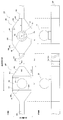
Classifications
-
- H—ELECTRICITY
- H10—SEMICONDUCTOR DEVICES; ELECTRIC SOLID-STATE DEVICES NOT OTHERWISE PROVIDED FOR
- H10F—INORGANIC SEMICONDUCTOR DEVICES SENSITIVE TO INFRARED RADIATION, LIGHT, ELECTROMAGNETIC RADIATION OF SHORTER WAVELENGTH OR CORPUSCULAR RADIATION
- H10F77/00—Constructional details of devices covered by this subclass
- H10F77/10—Semiconductor bodies
- H10F77/16—Material structures, e.g. crystalline structures, film structures or crystal plane orientations
- H10F77/169—Thin semiconductor films on metallic or insulating substrates
- H10F77/1698—Thin semiconductor films on metallic or insulating substrates the metallic or insulating substrates being flexible
-
- H—ELECTRICITY
- H02—GENERATION; CONVERSION OR DISTRIBUTION OF ELECTRIC POWER
- H02S—GENERATION OF ELECTRIC POWER BY CONVERSION OF INFRARED RADIATION, VISIBLE LIGHT OR ULTRAVIOLET LIGHT, e.g. USING PHOTOVOLTAIC [PV] MODULES
- H02S20/00—Supporting structures for PV modules
- H02S20/30—Supporting structures being movable or adjustable, e.g. for angle adjustment
- H02S20/32—Supporting structures being movable or adjustable, e.g. for angle adjustment specially adapted for solar tracking
-
- H—ELECTRICITY
- H02—GENERATION; CONVERSION OR DISTRIBUTION OF ELECTRIC POWER
- H02S—GENERATION OF ELECTRIC POWER BY CONVERSION OF INFRARED RADIATION, VISIBLE LIGHT OR ULTRAVIOLET LIGHT, e.g. USING PHOTOVOLTAIC [PV] MODULES
- H02S30/00—Structural details of PV modules other than those related to light conversion
- H02S30/10—Frame structures
-
- H—ELECTRICITY
- H02—GENERATION; CONVERSION OR DISTRIBUTION OF ELECTRIC POWER
- H02S—GENERATION OF ELECTRIC POWER BY CONVERSION OF INFRARED RADIATION, VISIBLE LIGHT OR ULTRAVIOLET LIGHT, e.g. USING PHOTOVOLTAIC [PV] MODULES
- H02S40/00—Components or accessories in combination with PV modules, not provided for in groups H02S10/00 - H02S30/00
- H02S40/20—Optical components
- H02S40/22—Light-reflecting or light-concentrating means
-
- H—ELECTRICITY
- H02—GENERATION; CONVERSION OR DISTRIBUTION OF ELECTRIC POWER
- H02S—GENERATION OF ELECTRIC POWER BY CONVERSION OF INFRARED RADIATION, VISIBLE LIGHT OR ULTRAVIOLET LIGHT, e.g. USING PHOTOVOLTAIC [PV] MODULES
- H02S40/00—Components or accessories in combination with PV modules, not provided for in groups H02S10/00 - H02S30/00
- H02S40/40—Thermal components
- H02S40/42—Cooling means
-
- H—ELECTRICITY
- H05—ELECTRIC TECHNIQUES NOT OTHERWISE PROVIDED FOR
- H05K—PRINTED CIRCUITS; CASINGS OR CONSTRUCTIONAL DETAILS OF ELECTRIC APPARATUS; MANUFACTURE OF ASSEMBLAGES OF ELECTRICAL COMPONENTS
- H05K1/00—Printed circuits
- H05K1/02—Details
- H05K1/0277—Bendability or stretchability details
- H05K1/028—Bending or folding regions of flexible printed circuits
-
- H—ELECTRICITY
- H05—ELECTRIC TECHNIQUES NOT OTHERWISE PROVIDED FOR
- H05K—PRINTED CIRCUITS; CASINGS OR CONSTRUCTIONAL DETAILS OF ELECTRIC APPARATUS; MANUFACTURE OF ASSEMBLAGES OF ELECTRICAL COMPONENTS
- H05K1/00—Printed circuits
- H05K1/18—Printed circuits structurally associated with non-printed electric components
- H05K1/189—Printed circuits structurally associated with non-printed electric components characterised by the use of flexible or folded printed circuits
-
- H—ELECTRICITY
- H10—SEMICONDUCTOR DEVICES; ELECTRIC SOLID-STATE DEVICES NOT OTHERWISE PROVIDED FOR
- H10F—INORGANIC SEMICONDUCTOR DEVICES SENSITIVE TO INFRARED RADIATION, LIGHT, ELECTROMAGNETIC RADIATION OF SHORTER WAVELENGTH OR CORPUSCULAR RADIATION
- H10F10/00—Individual photovoltaic cells, e.g. solar cells
-
- H—ELECTRICITY
- H10—SEMICONDUCTOR DEVICES; ELECTRIC SOLID-STATE DEVICES NOT OTHERWISE PROVIDED FOR
- H10F—INORGANIC SEMICONDUCTOR DEVICES SENSITIVE TO INFRARED RADIATION, LIGHT, ELECTROMAGNETIC RADIATION OF SHORTER WAVELENGTH OR CORPUSCULAR RADIATION
- H10F19/00—Integrated devices, or assemblies of multiple devices, comprising at least one photovoltaic cell covered by group H10F10/00, e.g. photovoltaic modules
- H10F19/90—Structures for connecting between photovoltaic cells, e.g. interconnections or insulating spacers
- H10F19/902—Structures for connecting between photovoltaic cells, e.g. interconnections or insulating spacers for series or parallel connection of photovoltaic cells
- H10F19/904—Structures for connecting between photovoltaic cells, e.g. interconnections or insulating spacers for series or parallel connection of photovoltaic cells characterised by the shapes of the structures
-
- H—ELECTRICITY
- H10—SEMICONDUCTOR DEVICES; ELECTRIC SOLID-STATE DEVICES NOT OTHERWISE PROVIDED FOR
- H10F—INORGANIC SEMICONDUCTOR DEVICES SENSITIVE TO INFRARED RADIATION, LIGHT, ELECTROMAGNETIC RADIATION OF SHORTER WAVELENGTH OR CORPUSCULAR RADIATION
- H10F77/00—Constructional details of devices covered by this subclass
- H10F77/40—Optical elements or arrangements
- H10F77/42—Optical elements or arrangements directly associated or integrated with photovoltaic cells, e.g. light-reflecting means or light-concentrating means
- H10F77/484—Refractive light-concentrating means, e.g. lenses
-
- H—ELECTRICITY
- H10—SEMICONDUCTOR DEVICES; ELECTRIC SOLID-STATE DEVICES NOT OTHERWISE PROVIDED FOR
- H10F—INORGANIC SEMICONDUCTOR DEVICES SENSITIVE TO INFRARED RADIATION, LIGHT, ELECTROMAGNETIC RADIATION OF SHORTER WAVELENGTH OR CORPUSCULAR RADIATION
- H10F77/00—Constructional details of devices covered by this subclass
- H10F77/93—Interconnections
- H10F77/933—Interconnections for devices having potential barriers
- H10F77/935—Interconnections for devices having potential barriers for photovoltaic devices or modules
- H10F77/939—Output lead wires or elements
-
- H—ELECTRICITY
- H05—ELECTRIC TECHNIQUES NOT OTHERWISE PROVIDED FOR
- H05K—PRINTED CIRCUITS; CASINGS OR CONSTRUCTIONAL DETAILS OF ELECTRIC APPARATUS; MANUFACTURE OF ASSEMBLAGES OF ELECTRICAL COMPONENTS
- H05K1/00—Printed circuits
-
- H—ELECTRICITY
- H05—ELECTRIC TECHNIQUES NOT OTHERWISE PROVIDED FOR
- H05K—PRINTED CIRCUITS; CASINGS OR CONSTRUCTIONAL DETAILS OF ELECTRIC APPARATUS; MANUFACTURE OF ASSEMBLAGES OF ELECTRICAL COMPONENTS
- H05K2201/00—Indexing scheme relating to printed circuits covered by H05K1/00
- H05K2201/04—Assemblies of printed circuits
- H05K2201/046—Planar parts of folded PCBs making an angle relative to each other
-
- H—ELECTRICITY
- H05—ELECTRIC TECHNIQUES NOT OTHERWISE PROVIDED FOR
- H05K—PRINTED CIRCUITS; CASINGS OR CONSTRUCTIONAL DETAILS OF ELECTRIC APPARATUS; MANUFACTURE OF ASSEMBLAGES OF ELECTRICAL COMPONENTS
- H05K2201/00—Indexing scheme relating to printed circuits covered by H05K1/00
- H05K2201/05—Flexible printed circuits [FPCs]
-
- H—ELECTRICITY
- H05—ELECTRIC TECHNIQUES NOT OTHERWISE PROVIDED FOR
- H05K—PRINTED CIRCUITS; CASINGS OR CONSTRUCTIONAL DETAILS OF ELECTRIC APPARATUS; MANUFACTURE OF ASSEMBLAGES OF ELECTRICAL COMPONENTS
- H05K2201/00—Indexing scheme relating to printed circuits covered by H05K1/00
- H05K2201/09—Shape and layout
- H05K2201/09209—Shape and layout details of conductors
- H05K2201/09218—Conductive traces
- H05K2201/09263—Meander
-
- H—ELECTRICITY
- H05—ELECTRIC TECHNIQUES NOT OTHERWISE PROVIDED FOR
- H05K—PRINTED CIRCUITS; CASINGS OR CONSTRUCTIONAL DETAILS OF ELECTRIC APPARATUS; MANUFACTURE OF ASSEMBLAGES OF ELECTRICAL COMPONENTS
- H05K2201/00—Indexing scheme relating to printed circuits covered by H05K1/00
- H05K2201/10—Details of components or other objects attached to or integrated in a printed circuit board
- H05K2201/10007—Types of components
- H05K2201/10121—Optical component, e.g. opto-electronic component
-
- H—ELECTRICITY
- H05—ELECTRIC TECHNIQUES NOT OTHERWISE PROVIDED FOR
- H05K—PRINTED CIRCUITS; CASINGS OR CONSTRUCTIONAL DETAILS OF ELECTRIC APPARATUS; MANUFACTURE OF ASSEMBLAGES OF ELECTRICAL COMPONENTS
- H05K2201/00—Indexing scheme relating to printed circuits covered by H05K1/00
- H05K2201/20—Details of printed circuits not provided for in H05K2201/01 - H05K2201/10
-
- H—ELECTRICITY
- H05—ELECTRIC TECHNIQUES NOT OTHERWISE PROVIDED FOR
- H05K—PRINTED CIRCUITS; CASINGS OR CONSTRUCTIONAL DETAILS OF ELECTRIC APPARATUS; MANUFACTURE OF ASSEMBLAGES OF ELECTRICAL COMPONENTS
- H05K3/00—Apparatus or processes for manufacturing printed circuits
-
- H—ELECTRICITY
- H05—ELECTRIC TECHNIQUES NOT OTHERWISE PROVIDED FOR
- H05K—PRINTED CIRCUITS; CASINGS OR CONSTRUCTIONAL DETAILS OF ELECTRIC APPARATUS; MANUFACTURE OF ASSEMBLAGES OF ELECTRICAL COMPONENTS
- H05K3/00—Apparatus or processes for manufacturing printed circuits
- H05K3/36—Assembling printed circuits with other printed circuits
-
- H—ELECTRICITY
- H05—ELECTRIC TECHNIQUES NOT OTHERWISE PROVIDED FOR
- H05K—PRINTED CIRCUITS; CASINGS OR CONSTRUCTIONAL DETAILS OF ELECTRIC APPARATUS; MANUFACTURE OF ASSEMBLAGES OF ELECTRICAL COMPONENTS
- H05K3/00—Apparatus or processes for manufacturing printed circuits
- H05K3/40—Forming printed elements for providing electric connections to or between printed circuits
-
- Y—GENERAL TAGGING OF NEW TECHNOLOGICAL DEVELOPMENTS; GENERAL TAGGING OF CROSS-SECTIONAL TECHNOLOGIES SPANNING OVER SEVERAL SECTIONS OF THE IPC; TECHNICAL SUBJECTS COVERED BY FORMER USPC CROSS-REFERENCE ART COLLECTIONS [XRACs] AND DIGESTS
- Y02—TECHNOLOGIES OR APPLICATIONS FOR MITIGATION OR ADAPTATION AGAINST CLIMATE CHANGE
- Y02E—REDUCTION OF GREENHOUSE GAS [GHG] EMISSIONS, RELATED TO ENERGY GENERATION, TRANSMISSION OR DISTRIBUTION
- Y02E10/00—Energy generation through renewable energy sources
- Y02E10/50—Photovoltaic [PV] energy
-
- Y—GENERAL TAGGING OF NEW TECHNOLOGICAL DEVELOPMENTS; GENERAL TAGGING OF CROSS-SECTIONAL TECHNOLOGIES SPANNING OVER SEVERAL SECTIONS OF THE IPC; TECHNICAL SUBJECTS COVERED BY FORMER USPC CROSS-REFERENCE ART COLLECTIONS [XRACs] AND DIGESTS
- Y02—TECHNOLOGIES OR APPLICATIONS FOR MITIGATION OR ADAPTATION AGAINST CLIMATE CHANGE
- Y02E—REDUCTION OF GREENHOUSE GAS [GHG] EMISSIONS, RELATED TO ENERGY GENERATION, TRANSMISSION OR DISTRIBUTION
- Y02E10/00—Energy generation through renewable energy sources
- Y02E10/50—Photovoltaic [PV] energy
- Y02E10/52—PV systems with concentrators
Definitions
- the present invention relates to a power generation module and a wiring board, and more particularly to a power generation module and a wiring board including a flexible printed circuit board.
- Patent Document 1 discloses the following technology. That is, the concentrating solar cell module includes a plurality of solar cell elements, a long receiver substrate in which the solar cell elements are placed in a row at a predetermined interval, and the receiver substrate. A plurality of module boards placed in parallel at a certain interval, and the receiver board has a long receiver base and a longitudinal direction with its ends facing each other on the receiver base.
- a plurality of wiring members arranged in a row along a line, wherein a positive electrode pad portion is provided at one end portion of the wiring material, and a negative electrode pad portion is provided at the other end portion, and the positive electrode A positive electrode terminal and a negative electrode terminal of the solar cell element are connected to the pad portion and the negative electrode pad portion, respectively, to constitute a solar cell element mounting portion.
- the solar cell element when sunlight is converged on the solar cell element by the lens, the solar cell element becomes high temperature. Since the heat of the solar cell element is transmitted to the receiver substrate on which the solar cell element is mounted, the receiver substrate may thermally expand.
- the receiver substrate may be peeled off from the member due to the influence of condensation or the like.
- the power generation efficiency of the solar cell element may be reduced.
- the present invention has been made to solve the above-described problems, and an object thereof is to provide a power generation module and a wiring board capable of suppressing a decrease in power generation efficiency due to the influence of heat or the influence of condensation. It is.
- a power generation module includes a power generation unit including a power generation element and a wiring board, and the wiring board includes a reinforcing plate and a flexible printed circuit board provided on the reinforcing plate.
- the flexible printed circuit board includes an FPC land portion on which the power generation unit is mounted and an FPC wiring portion connected to the FPC land portion, and the width of the FPC wiring portion is equal to the width of the FPC land portion. Smaller than.
- a wiring board has a power generation portion mounted thereon, and includes a land portion and a wiring portion, and the land portion has the power generation portion mounted on the land portion.
- a width of the wiring portion is smaller than a width of the land portion, and the land portion and the wiring portion are formed of a reinforcing plate formed of metal, and a flexible printed circuit board provided on the reinforcing plate.
- the land portion has a first region and a second region, the first region has a first width, and the second region is in the length direction of the land portion.
- At least one end connected to the first region, and having a second width, the first width being larger than the second width, in the width direction of the land portion
- the edge of the first area located at the end of the first area and the edge of the first area Is, an angle between the edge of the second region on the edge of the second region in the width direction is greater than 90 degrees, and is less than 170 degrees.
- a wiring board on which a power generation unit is mounted includes a land portion and a wiring portion, and the land portion includes the land portion. It has a shape on which the power generation unit is mounted, and the width of the wiring part is smaller than the width of the land part,
- the land portion and the wiring portion include a reinforcing plate made of metal and a flexible printed circuit board provided on the reinforcing plate, and the land portion has a first region and a second region.
- the first region has a first width
- the second region is located at at least one end in the length direction of the land portion, and is connected to the first region, and Having a width of 2;
- the first width is larger than the second width, and is connected to an edge of the first region located at an end of the first region in a width direction of the land portion, and an edge of the first region,
- the connecting portion with the edge of the second region located at the end of the second region in the width direction is a curve.
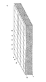
- FIG. 1 is a perspective view of a photovoltaic power generation apparatus according to the first embodiment of the present invention.
- FIG. 2 is a perspective view of the photovoltaic power generation module according to the first embodiment of the present invention.
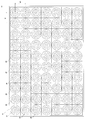
- FIG. 3 is a plan view of the photovoltaic power generation module according to the first embodiment of the present invention.
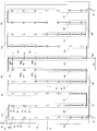
- FIG. 4 is a plan view showing a state in which the light collecting unit is removed from the photovoltaic power generation module according to the first embodiment of the present invention.
- FIG. 5 is a perspective view showing a state where the power generation unit is mounted on the wiring board according to the first embodiment of the present invention.
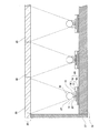
- FIG. 6 is a cross-sectional view showing a cross section taken along line VI-VI in FIG.
- FIG. 7 is a cross-sectional view showing a cross section taken along line VII-VII in FIG. 4 of the wiring module and the power generation unit in the solar power generation module according to the first embodiment of the present invention.
- FIG. 8 is a diagram showing a pattern of the conductive portion of the FPC in the wiring board according to the first embodiment of the present invention.
- FIG. 9 is a diagram showing a wiring board according to the first embodiment of the present invention.
- FIG. 10 is a diagram showing an FPC in the wiring board according to the first embodiment of the present invention.
- FIG. 11 is a diagram showing a reinforcing plate in the wiring board according to the first embodiment of the present invention.
- FIG. 12 is a diagram showing a wiring module in the wiring board according to the first embodiment of the present invention.
- FIG. 13 is a view showing a modification of the wiring board according to the first embodiment of the present invention.
- FIG. 14 is a view showing a modification of the wiring board according to the first embodiment of the present invention.
- FIG. 15 is a view showing a modification of the wiring board according to the first embodiment of the present invention.
- FIG. 16 is a view showing a modification of the wiring board according to the first embodiment of the present invention.
- FIG. 17 is a view showing a modification of the FPC in the wiring board according to the first embodiment of the present invention.
- FIG. 18 is a view showing a modification of the FPC in the wiring board according to the first embodiment of the present invention.
- FIG. 19 is a view showing a modification of the FPC in the wiring board according to the first embodiment of the present invention.
- FIG. 20 is a diagram showing a modification of the FPC in the wiring board according to the first embodiment of the present invention.
- FIG. 21 is a perspective view showing a state in which the power generation unit is mounted on the wiring board according to the second embodiment of the present invention.
- FIG. 22 is a cross-sectional view showing a cross section taken along a line corresponding to line VI-VI in FIG. 4 of the photovoltaic power generation module according to the second embodiment of the present invention.
- FIG. 23 is a cross-sectional view showing a cross section taken along a line corresponding to the line VII-VII in FIG. 4 of the wiring module and the power generation unit in the solar power generation module according to the second embodiment of the present invention.
- FIG. 24 is a diagram showing a wiring board according to the second embodiment of the present invention.
- a power generation module includes a power generation unit including a power generation element and a wiring board, and the wiring board includes a reinforcing plate and a flexible printed circuit board provided on the reinforcing plate.
- the flexible printed circuit board includes an FPC land part on which the power generation part is mounted, and an FPC wiring part connected to the FPC land part, and the width of the FPC wiring part is equal to that of the FPC land part. Less than width.
- the wiring board having a certain degree of flexibility can be given a property that the wiring part is more easily bent than the land part.
- the wiring portion is bent so as to absorb the expansion in the extending direction.
- the deformation and displacement of the land portion can be prevented.
- the lens which makes the said electric power generation part a focus is provided above the electric power generation part mounted in the land part, it can prevent that the position of an electric power generation part remove
- the FPC land part has a length along the extending direction of the wiring board, and the FPC wiring part has a length along the extending direction of the wiring board, and the FPC The length of the wiring part is larger than the length of the FPC land part.
- Such a configuration makes it possible to bend the FPC wiring part more easily than the FPC land part, so that the position of the power generation part can be prevented more reliably from being out of focus of the lens.
- the length of the FPC wiring portion is greater than 100% and not more than 600% of the length of the FPC land portion.
- the land portion can be made more difficult to bend than the wiring portion while having a size that allows the power generation portion to be mounted.
- the width of the FPC wiring portion is not less than 0.1% and not more than 50% of the width of the FPC land portion.
- the width of the wiring portion can be reduced on the basis of the width of the land portion, so that the wiring portion can be more easily bent than the land portion. Further, the width of the wiring portion can be increased to such an extent that the strength of the wiring portion does not matter.
- the FPC land portion has a first region and a second region, the first region has a first width, and the second region is formed of the FPC land portion. Located at at least one end in the length direction, connected to the first region, and having a second width, the second width being smaller than the first width, and It is larger than the width of the FPC wiring part.
- heat transferred from the power generation unit to the first region can be efficiently released to the wiring unit via the second region.
- the FPC land portion includes a first region and a second region, the first region has a first width, and the second region is formed of the FPC land portion. Located at both ends in the length direction and connected to the first region and having a second width, the second width being smaller than the first width and the FPC It is larger than the width of the wiring part.
- the heat in the first region can be released to both wiring parts connected to each second region.
- the second width decreases as the FPC wiring portion is approached from the first region.
- the heat in the second region can be efficiently released to the wiring portion.
- the second region has a length along the extending direction of the wiring board, and a relationship between the second width and the length of the second region satisfies the following expression. . 0 ⁇ (Lf12 / Wf2) ⁇ 10
- Wf2 is the second width
- Lf12 is the length of the second region.
- the heat in the second region can be more efficiently released to the wiring portion.
- the power generation unit is arranged such that a central portion of the power generation unit is included in the first region in a plan view from above the wiring board.
- the power generation unit can be arranged at a position away from the wiring unit to some extent, so that it is possible to more reliably prevent the position of the power generation unit from being shifted due to the influence of the bending of the wiring unit.
- the area of the FPC land portion is 20% or more and 1000% or less of the area of the FPC wiring portion.
- the land portion can be made more difficult to bend than the wiring portion while having a size that allows the power generation portion to be mounted.
- the reinforcing plate includes a land reinforcing portion fixed to the FPC land portion and a wiring reinforcing portion fixed to the FPC wiring portion, and the width of the wiring reinforcing portion is set to the land. It is smaller than the width of the reinforcing part.
- Such a configuration can make the wiring portion more easily bent than the land portion.
- the reinforcing plate is bonded to the base portion by an adhesive layer, and the adhesive layer includes a land bonding region for bonding the land reinforcing portion to the base portion, and the wiring reinforcing portion to the base portion. And a width of the wiring bonding area is smaller than a width of the land bonding area.
- the wiring reinforcing portion is more easily separated from the base portion than the land reinforcing portion.
- the wiring portion and the wiring reinforcing portion that are fixed to each other are expanded in the stretching direction.
- the FPC land portion has a first region and a second region, the first region has a first width, and the second region is formed of the FPC land portion.
- the FPC land is located at at least one end in the length direction, is connected to the first region, and has a second width, the first width being larger than the second width.
- the angle formed with the edge is greater than 90 degrees and less than or equal to 170 degrees.
- the FPC land portion has a first region and a second region, the first region has a first width, and the second region is formed of the FPC land portion.
- the FPC land is located at at least one end in the length direction, is connected to the first region, and has a second width, the first width being larger than the second width.
- An edge of the first region located at the end of the first region in the width direction of the portion, and an edge of the second region connected to the edge of the first region and located at the end of the second region in the width direction The connection with the edge forms a curve.
- the configuration in which the land is rounded to reduce the corners can more reliably prevent the flexible printed circuit board and the reinforcing plate from being peeled off due to the influence of condensation.
- connection portion between the edge of the first region and the edge of the second region forms a continuous curve.
- the periphery of the land portion can be made smoother, so that the flexible printed circuit board and the reinforcing plate can be more reliably prevented from being peeled off due to the influence of condensation.
- a wiring board has a power generation portion mounted thereon, and includes a land portion and a wiring portion, and the land portion is mounted on the land portion.
- the width of the wiring portion is smaller than the width of the land portion, and the land portion and the wiring portion are formed of a reinforcing plate made of metal, and a flexible print provided on the reinforcing plate.
- the land portion has a first region and a second region, the first region has a first width, and the second region has a length direction of the land portion.
- an angle between the edge of the second region on the edge of the second region in the width direction is greater than 90 degrees, and is less than 170 degrees.
- the configuration in which the corner of the land portion is obtuse for example, when the flexible printed circuit board and the reinforcing plate in the wiring board are bonded, the flexible printed circuit board at the corner of the land portion due to the influence of dew condensation etc. And peeling between the reinforcing plate and the reinforcing plate can be suppressed.
- the wiring board and the base part on which the wiring board is placed are bonded, it is possible to suppress peeling of the land part from the base part due to the influence of condensation or the like. Therefore, it is possible to suppress a decrease in power generation efficiency due to the influence of condensation.
- a wiring board according to an embodiment of the present invention is mounted with a power generation unit, and the wiring board includes a land part and a wiring part, and the land part is on the land part.
- the power generation part has a shape to be mounted, the width of the wiring part is smaller than the width of the land part, and the land part and the wiring part are formed on a reinforcing plate made of metal, and on the reinforcing plate
- the configuration in which the land portion is rounded to reduce the corners for example, when the flexible printed circuit board and the reinforcing plate are bonded to each other on the wiring board, the flexible printed circuit board and the reinforcing plate due to the influence of condensation, etc. Peeling can be suppressed.
- the wiring board and the base part on which the wiring board is placed are bonded, it is possible to suppress peeling of the land part from the base part due to the influence of condensation or the like. Therefore, it is possible to suppress a decrease in power generation efficiency due to the influence of condensation.
- the connecting portion between the edge of the first region and the edge of the second region forms a continuous curve.
- the periphery of the land portion can be made smoother, so that the flexible printed circuit board and the reinforcing plate can be more reliably prevented from being peeled off due to the influence of condensation. Further, it is possible to more reliably prevent the land portion from being peeled off from the base portion due to the influence of condensation.
- FIG. 1 is a perspective view of a photovoltaic power generation apparatus according to the first embodiment of the present invention.
- the solar power generation device 101 includes a solar power generation panel 12 and a gantry 40.
- the photovoltaic power generation panel 12 includes a plurality of photovoltaic power generation modules 10, a solar direction sensor 13, and a frame portion 14.
- the gantry 40 includes a base 46, a support column 48, a functional unit 90, and a position variable unit (not shown).
- the solar power generation device 101 is, for example, a concentrating solar power generation device.
- the solar power generation panel 12 includes, for example, five rows and five columns of solar power generation modules 10, that is, 25 solar power generation modules 10. Each photovoltaic power generation module 10 is mounted side by side on top of the frame portion 14.
- the photovoltaic power generation module 10 receives sunlight to generate power, and outputs the generated DC power to the functional unit 90 attached to the side surface of the support column 48 using wiring (not shown).
- the support column 48 is erected perpendicularly to the ground, for example, on a base 46 provided on the ground.
- the position variable unit (not shown) includes a motor and directs the direction of the light receiving surface FL in the photovoltaic power generation panel 12, that is, the normal direction of the light receiving surface FL indicated by the arrow As, to the sun based on a control signal from the function unit 90. To work. Thereby, the direction of the light receiving surface FL in the photovoltaic power generation panel 12 changes so as to track the sun from sunrise to sunset.
- the solar direction sensor 13 is used to detect the direction of the sun, and outputs a sensor signal indicating the detection result to the functional unit 90.
- the functional unit 90 includes, for example, a housing and various units housed in the housing. Specifically, for example, in the casing, a connection box for connecting wiring from each solar power generation module 10, a power conditioner that converts DC power output from the solar power generation module 10 into AC power, and A control unit and the like for controlling the direction of the light receiving surface FL in the photovoltaic power generation panel 12 are accommodated.
- FIG. 2 is a perspective view of the photovoltaic power generation module according to the first embodiment of the present invention.
- FIG. 3 is a plan view of the photovoltaic power generation module according to the first embodiment of the present invention.
- solar power generation module 10 includes a wall portion 27, a bottom portion (not shown), and a light collecting portion 25.
- the light collecting unit 25 includes a plurality of Fresnel lenses 26.
- the Fresnel lens 26 is arranged in a square lattice, for example. Specifically, the Fresnel lenses 26 are arranged such that, for example, the distance between the centers of adjacent Fresnel lenses 26 is the same W1.
- the size of the Fresnel lens 26 is, for example, 50 mm ⁇ 50 mm.
- FIG. 4 is a plan view showing a state in which the light collecting unit is removed from the photovoltaic power generation module according to the first embodiment of the present invention.
- solar power generation module 10 includes a wall portion 27, a wiring module 49, a plurality of power generation units 30, and two lead wires 39.
- the wiring module 49 includes a base portion 38 that is the bottom of the photovoltaic power generation module 10 and a wiring board 69.
- the wiring board 69 includes strip-shaped boards 32A, 32B, 32C, 32D, 32E, 32F, 32G, 32H, 32I, and 32J, and connecting portions 33H, 33I, 33J, 33K, 33L, 33M, 33N, 33O, and 33P. .
- the connecting portion 33H connects the strip substrate 32A and the strip substrate 32B.
- the connecting portion 33I connects the strip substrate 32B and the strip substrate 32C.
- the connecting portion 33J connects the strip substrate 32C and the strip substrate 32D.
- the connecting portion 33K connects the strip substrate 32D and the strip substrate 32E.
- the connecting portion 33L connects the strip substrate 32E and the strip substrate 32F.
- the connecting portion 33M connects the strip substrate 32F and the strip substrate 32G.
- the connecting portion 33N connects the strip substrate 32G and the strip substrate 32H.
- the connecting portion 33O connects the strip substrate 32H and the strip substrate 32I.
- the connecting portion 33P connects the strip substrate 32I and the strip substrate 32J.
- each of the strip-shaped substrates 32A, 32B, 32C, 32D, 32E, 32F, 32G, 32H, 32I, and 32J is also referred to as a strip-shaped substrate 32.
- each of the connecting portions 33H, 33I, 33J, 33K, 33L, 33M, 33N, 33O, and 33P is also referred to as a connecting portion 33.
- Each strip substrate 32 is arranged in parallel to each other.
- the wiring board 69 may further include a large number or a small number of strip-shaped substrates 32.
- the wiring board 69 may be configured to include one strip-shaped board 32.
- the wiring board 69 specifically, the belt-like board 32 of the wiring board 69 is long.
- the strip substrate 32 of the wiring substrate 69 has a length along the extending direction.
- the wiring board 69 has a thickness.
- the wiring board 69 has a width along the direction intersecting the length and thickness of the wiring board 69.
- a lead wire 39 is connected to each of the two ends of the wiring board 69.
- the lead wire 39 passes through a through hole provided in the base portion 38 and is connected to, for example, a connection box in the functional portion 90 shown in FIG.
- the material of the base portion 38 is, for example, aluminum or copper having high heat conductivity and relatively light weight.
- the wiring board 69 is placed on and adhered to the main surface on the upper side of the base portion 38, that is, the main surface on the Fresnel lens 26 side of the base portion 38.
- the belt-like substrate 32 of the wiring board 69 includes seven land parts 60 and wiring parts 63 connected to both sides of each land part.
- the wiring part 63 connects the land parts 60 to each other.
- the width of the land portion 60 is larger than the width of the wiring portion 63.
- the power generation unit 30 is mounted on the main surface on the upper side of the land unit 60.
- the belt-like substrate 32 in the wiring substrate 69 may be configured to further include a large number or a small number of land portions 60 and wiring portions 63.
- the belt-like substrate 32 may be configured to include one land portion 60 and one wiring portion 63.
- power generation units 30P1, 30Q1, and 30R1 are mounted as the power generation unit 30 on the belt-like substrate 32E.
- power generation units 30P2, 30Q2, and 30R2 are mounted on the belt-like substrate 32F as the power generation unit 30.
- the power generation unit 30P1 and the power generation unit 30P2 are aligned and adjacent to each other along a direction perpendicular to the extending direction of the strip substrate 32.
- the power generation unit 30Q1 and the power generation unit 30Q2 are arranged adjacent to each other along a direction perpendicular to the extending direction of the belt-like substrate 32.
- the power generation unit 30R1 and the power generation unit 30R2 are arranged adjacent to each other along the direction perpendicular to the extending direction of the belt-like substrate 32.
- the distance W2 between the power generation units 30 that are arranged in the direction perpendicular to the extending direction of the strip-shaped substrate 32 and that are adjacent to each other is equal to the distance W3 between the power generation units 30 that are adjacent to each other in the strip-shaped substrate 32.
- the distance W2 between the power generation unit 30P1 and the power generation unit 30P2 is equal to the distance W3 between the power generation unit 30P2 and the power generation unit 30Q2.
- the distance W2 and the distance W3 are equal to the distance W1 between the centers of the Fresnel lenses 26 shown in FIG.
- Fresnel lens 26 shown in FIG. 3 is provided for one power generation unit 30.
- Each power generation unit 30 is disposed on the optical axis of the corresponding Fresnel lens 26.
- the solar power generation module 10 includes a power generation module 29.
- the power generation module 29 includes a wiring board 69 and a power generation unit 30 mounted on the wiring board 69.
- the wiring board 69 includes the land portion 60 and the wiring portion 63 as described above.
- FIG. 5 is a perspective view showing a state where the power generation unit is mounted on the wiring board according to the first embodiment of the present invention.
- the wiring board 69 includes an FPC (Flexible Printed Circuit) 79 and a reinforcing plate 89.
- the FPC 79 includes a conductive portion 77 and an insulating portion 78 that covers the conductive portion 77.
- the power generation unit 30 is mounted on the land portion 60 of the wiring board 69. Specifically, in the land portion 60, an opening 68 is provided in the FPC 79. In the opening 68, since the insulating part 78 does not cover the upper side of the conductive part 77, the conductive part 77 is exposed. The power generation unit 30 is electrically connected to the conductive unit 77 at the opening 68.
- the reinforcing plate 89 is provided on the main surface of the wiring board 69 on the base portion 38 side of the belt-like substrate 32, gives the belt-like substrate 32 a slight hardness, and the wiring board 69 at the time of manufacturing the photovoltaic power generation module 10. Easy handling.
- the reinforcing plate 89 is made of a metal such as aluminum or copper.
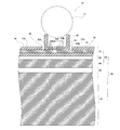
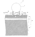
- FIG. 6 is a cross-sectional view showing a cross section taken along line VI-VI in FIG. 4 of the photovoltaic power generation module according to the first embodiment of the present invention.
- the power generation unit 30 includes a ball lens 17, a package 18, and a power generation element 19. Note that the power generation unit 30 may have a configuration that does not include all or part of the components other than the power generation element 19.
- the wiring board 69 is placed on the upper main surface of the base portion 38.
- the reinforcing plate 89 is provided on the base portion 38.
- the FPC 79 is provided on the reinforcing plate 89. Specifically, the FPC 79 is provided on the base portion 38 via the reinforcing plate 89.
- the power generation element 19 is housed in the package 18.
- the power generating element 19 is mounted on the FPC 79 while being housed in the package 18.
- the electrode of the power generation element 19 (not shown) is connected to the conductive portion 77 of the FPC 79 via the package electrode 20 provided so as to penetrate the bottom of the package 18.
- the size of the power generation element 19 is, for example, 3.2 mm ⁇ 3.2 mm.
- the Fresnel lens 26 converges sunlight on the corresponding ball lens 17.
- the ball lens 17 further converges the sunlight converged by the Fresnel lens 26 onto the power generation element 19.
- the power generation element 19 receives sunlight converged by the Fresnel lens 26 and the ball lens 17 and generates electric power corresponding to the amount of received light.
- FIG. 7 is a cross-sectional view showing a cross section taken along line VII-VII in FIG. 4 of the wiring module and the power generation unit in the solar power generation module according to the first embodiment of the present invention.
- FIG. 7 also shows an adhesive layer not shown in FIG. 5, for example.
- power generation unit 30 is mounted on wiring module 49, specifically, wiring board 69 in wiring module 49.
- the FPC 79 and the reinforcing plate 89 are bonded by the in-board adhesive layer 58.
- the wiring board 69 and the base portion 38 are bonded by the base adhesive layer 59.
- the in-substrate adhesive layer 58 and the base adhesive layer 59 are formed by, for example, an adhesive or an adhesive tape.
- the power generation element 19 has an element electrode 42A and an element electrode 42B, and outputs a voltage from the element electrode 42A and the element electrode 42B.
- Package 18 includes package electrode 20A and package electrode 20B.
- the package electrode 20A and the package electrode 20B are provided so as to penetrate the bottom portion of the package 18, and are exposed on both the upper side and the lower side of the bottom portion.
- the element electrode 42A of the power generation element 19 is connected to the package electrode 20A by wire bonding, for example.
- the element electrode 42B is connected to the package electrode 20B by, for example, a conductive paste.
- the insulating portion 78 does not cover the upper side of the conductive portion 77, a part of the conductive portion 77, specifically, a portion of the conductive portion 77A and a portion of the conductive portion 77B are exposed. Yes.
- the package electrode 20A and the package electrode 20B are connected to the conductive portion 77A and the conductive portion 77B, for example, by soldering.
- the package 18 supports the ball lens 17 at the end of its side wall, and fixes the focal point of the ball lens 17 to the power generation element 19.
- FIG. 8 is a diagram showing a pattern of the conductive portion of the FPC in the wiring board according to the first embodiment of the present invention.
- a part of the conductive portion 77 is exposed at the opening 68 of the FPC 79. Specifically, in the opening 68, a part of the conductive part 77A and the conductive part 77B are exposed.
- the conductive portion 77A and the conductive portion 77B are connected to the element electrode 42A and the element electrode 42B of the power generating element 19, respectively, for example, as shown in FIG.
- the conductive unit 77 connects, for example, the power generation unit 30 mounted on the land unit 60 and the power generation unit 30 mounted on the land unit 60 adjacent to the land unit 60 in series.
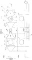
- FIG. 9 is a diagram showing a wiring board according to the first embodiment of the present invention.
- FIG. 9 shows a plan view and a side view of a part of the wiring board 69, specifically, a part of the belt-like board 32 in the wiring board 69.
- wiring board 69 on which power generation unit 30 is mounted includes a plurality of land portions 60 and a plurality of wiring portions 63 as described above.
- the land portion 60 has a shape in which the power generation unit 30 is mounted on the main surface on the upper side thereof, that is, on the Fresnel lens 26 side. That is, the land part 60 has a size that allows the power generation part 30 to be mounted.
- the land portion 60 has a length Lb1 along the extending direction of the wiring board 69.
- the power generation unit 30 including the power generation element 19 is mounted on the land unit 60.
- the wiring part 63 is electrically connected to the power generation element 19.
- the wiring part 63 electrically connects the adjacent land part 60, that is, the adjacent power generation part 30.
- the wiring part 63 has a length Lb2 along the extending direction of the wiring board 69.
- the length Lb2 of the wiring part 63 is larger than the length Lb1 of the land part 60. That is, the length Lb2 of the wiring part 63 in the extending direction of the wiring board 69 is larger than the length Lb1 of the land part 60 in the extending direction.
- the extending direction of the wiring board 69 is also referred to as a substrate extending direction.
- the width Wb3 of the wiring part 63 is smaller than the width Wb0 of the land part 60.
- the width Wb0 of the land portion 60 and the width Wb3 of the wiring portion 63 are respectively the direction intersecting the substrate extending direction, specifically, for example, the length of the land portion 60 and the wiring portion 63 in the direction perpendicular to the substrate extending direction. Is the length of Hereinafter, the direction intersecting the substrate extending direction, that is, the width direction of the land portion 60 is also referred to as a substrate width direction.
- the width Wb0 of the land portion 60 is, for example, 200% or more and 1000% or less of the width Wb3 of the wiring portion 63.
- the length Lb1 of the land portion 60 in the substrate extending direction is larger than the width Wb0 of the land portion 60.
- the land portion 60 has an inner region 61 and two outer regions 62.
- Each outer region 62 is connected to both ends of the inner region 61 in the substrate extending direction. That is, each outer region 62 is located at both ends in the length direction of the land portion 60 and is connected to the inner region 61. That is, the outer region 62 is connected between the end portion of the inner region 61 in the substrate extending direction and the wiring portion 63.
- the land portion 60 may have one outer region 62.
- the outer region 62 is connected to, for example, one end of the inner region 61 in the substrate extending direction. That is, the outer region 62 is located at one end in the length direction of the land portion 60 and is connected to the inner region 61.
- the inner region 61 has a width Wb1 corresponding to the width Wb0 of the land portion 60.
- the outer region 62 has a width Wb2.
- the width Wb1 of the inner region 61 and the width Wb2 of the outer region 62 are the length of the inner region 61 and the length of the outer region 62 in the substrate width direction, respectively.
- the width Wb2 of the outer region 62 is smaller than the width Wb1 of the inner region 61. Further, for example, the width Wb ⁇ b> 2 of the outer region 62 is larger than the width Wb ⁇ b> 3 of the wiring part 63.
- the width Wb2 of the outer region 62 continuously decreases as the distance from the inner region 61 to the wiring portion 63 increases. That is, the width Wb2 of the outer region 62 continuously decreases as the wiring portion 63 to which the outer region 62 is connected is approached.
- the outer region 62 has a length Lb12 along the extending direction of the wiring board 69.
- the relationship between the width Wb2 of the outer region 62 and the length Lb12 of the wiring portion 63, that is, the length Lb12 of the outer region 62 in the substrate extending direction is expressed by the following equation (1). 0 ⁇ Lb12 / Wb2 ⁇ 10 (1)
- the area Sb1 of the inner region 61 is larger than the area Sb2 of the outer region 62.
- the area Sb1 of the inner region 61 is 200% or more and 1000% or less of the area Sb2 of the outer region 62.
- the wiring board 69 includes, for example, the FPC 79 and the reinforcing plate 89 as described above. That is, each of the land portion 60 and the wiring portion 63 includes a reinforcing plate 89.
- the power generation unit 30 in a plan view from above the wiring board 69, specifically, in a plan view in the direction from the top of the wiring board 69 to the mounting surface of the power generation unit 30, Has a shape in which the power generation unit 30 is arranged so that the center Ce of the power generation unit 30 is located in the inner region 61.
- the power generation unit 30 is arranged so that its center Ce is included in the inner region 61 in plan view from above the wiring board 69.
- the distance db1 from the power generation unit 30 to the wiring unit 63 in the substrate extending direction is the distance db2 from the power generation unit 30 to the end of the land unit 60 in the substrate width direction. Greater than.
- the wiring board 69 has an electrode for soldering the power generation unit 30.
- the electrode is an exposed portion of the conductive portion 77 in the opening 68 shown in FIG. 8 and is provided so as to be included in the inner region 61.
- the land portion 60 has a mounting region 31 that comes into contact with the power generation unit 30 when the power generation unit 30 is mounted on the land unit 60.
- 80% or more of the mounting area 31 is located in the inner area 61.
- 80% to 100% of the mounting region 31 in which the power generation unit 30 is mounted in the land portion 60 is included in the inner region 61.
- 100% of the mounting area 31 is included in the inner area 61.
- the thickness Tb3 of the wiring part 63 is 1% or more and 50% or less of the width Wb3 of the wiring part 63.
- the reinforcing plate 89 has a thickness Ts0.
- the thickness Ts0 of the reinforcing plate 89 is 10% or more and 90% or less of the thickness Tb0 of the wiring board 69.
- the inner region 61 has an edge 65.
- the edge 65 is located at the end of the inner region 61 in the substrate width direction.
- the outer region 62 has an edge 66.
- the edge 66 is located at the end of the outer region 62 in the substrate width direction.
- Edge 65 and edge 66 are connected to each other.
- the angle ⁇ formed by the edge 65 and the edge 66 is, for example, greater than 90 degrees and 170 degrees or less.
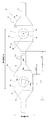
- FIG. 10 is a diagram showing an FPC in the wiring board according to the first embodiment of the present invention.
- FPC 79 includes a plurality of FPC land portions 70 and a plurality of FPC wiring portions 73.
- the FPC land portion 70 and the FPC wiring portion 73 are included in the land portion 60 and the wiring portion 63 shown in FIG.
- the power generation unit 30 is mounted on the FPC land unit 70.
- the FPC wiring part 73 connects the FPC land parts 70, that is, the power generation parts 30.
- the FPC land portion 70 has a length Lf1 along the extending direction of the wiring board 69.
- the FPC wiring portion 73 has a length Lf3 along the extending direction of the wiring board 69.
- the length Lf3 of the FPC wiring portion 73 is larger than the length Lf1 of the FPC land portion 70. That is, the length Lf3 of the FPC wiring portion 73 in the substrate extending direction is larger than the length Lf1 of the FPC land portion 70 in the substrate extending direction.
- the length Lf3 of the FPC wiring portion 73 in the substrate extending direction is greater than 100% and 600% or less of the length Lf1 of the FPC land portion 70 in the substrate extending direction.
- the width Wf3 of the FPC wiring part 73 is smaller than the width Wf0 of the FPC land part 70. Specifically, for example, the width Wf3 of the FPC wiring portion 73 is not less than 0.1% of the width Wf0 of the FPC land portion 70 and not more than 50%.
- the area Sf1 of the FPC land part 70 is 20% or more and 1000% or less of the area Sf3 of the FPC wiring part 73.
- the FPC land portion 70 has an inner region (first region) 71 and two outer regions (second regions) 72.
- Inner region 71 has a width Wf1.
- the outer region 72 has a width Wf2.
- the outer region 72 is located at both ends in the length direction of the FPC land portion 70 and is connected to the inner region 71.
- each outer region 72 is connected to both ends of the inner region 71 in the substrate extending direction, for example. Specifically, the outer region 72 is connected between the end portion of the inner region 71 in the substrate extending direction and the FPC wiring portion 73.
- the FPC land portion 70 may have only one outer region 72.
- the outer region 72 is connected to one end of the inner region 71 in the substrate extending direction. That is, the outer region 72 is located at one end in the length direction of the FPC land portion 70 and is connected to the inner region 71.
- the inner region 71 has a width Wf1 corresponding to the width Wf0 of the FPC land portion 70.
- the outer region 72 has a width Wf2.
- the width Wf1 of the inner region 71 and the width Wf2 of the outer region 72 are the length of the inner region 71 and the length of the outer region 72 in the substrate width direction, respectively.
- the width Wf2 of the outer region 72 is smaller than the width Wf1 of the inner region 71. Further, for example, the width Wf2 of the outer region 72 is larger than the width Wf3 of the FPC wiring portion 73.
- the width Wf2 of the outer region 72 continuously decreases as the FPC wiring portion 73 is approached from the inner region 71. That is, the width Wf ⁇ b> 2 of the outer region 72 continuously decreases as the FPC wiring portion 73 connected to the outer region 72 is approached.
- the outer region 72 has a length Lf12 along the extending direction of the wiring board 69.
- the relationship between the width Wf2 of the outer region 72 and the length Lf12 of the outer region 72, that is, the length Lf12 of the outer region 72 in the substrate stretching direction is expressed by the following equation (2). 0 ⁇ Lf12 / Wf2 ⁇ 10 (2)
- the power generation unit 30 is arranged such that its own central portion, specifically, its own center Ce is included in the inner region 71.
- the FPC 79 has an electrode for soldering the power generation unit 30, for example.
- the electrode is an exposed portion of the conductive portion 77 in the opening 68 shown in FIG. 8 and is provided so as to be included in the inner region 71.
- the inner region 71 has an edge 75.
- the edge 75 is located at the end of the inner region 71 in the width direction of the FPC land portion 70, that is, the substrate width direction.
- the outer region 72 has an edge 76.
- the edge 76 is located at the end of the outer region 72 in the substrate width direction.
- Edge 75 and edge 76 are connected to each other.
- the angle ⁇ formed by the edge 75 and the edge 76 is, for example, greater than 90 degrees and 170 degrees or less.
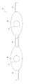
- FIG. 11 is a view showing a reinforcing plate in the wiring board according to the first embodiment of the present invention.
- the reinforcing plate 89 has a land reinforcing portion 80 and a wiring reinforcing portion 83.
- Land reinforcing portion 80 and wiring reinforcing portion 83 are included in land portion 60 and wiring portion 63 shown in FIG. 9, respectively.
- the land reinforcing portion 80 is bonded to the FPC land portion 70.
- the wiring reinforcing part 83 is bonded to the FPC wiring part 73.
- the width Ws3 of the wiring reinforcing portion 83 is smaller than the width Ws0 of the land reinforcing portion 80.
- FIG. 12 is a diagram showing a wiring module in the wiring board according to the first embodiment of the present invention.
- FIG. 12 shows a plan view and a side view of the state in which the wiring board 69 is bonded to the base portion 38 by the base adhesive layer 59, that is, a plan view and a side view of the wiring module 49.
- the base adhesive layer 59 includes a land adhesive region 50 for bonding the land portion 60 of the wiring board 69 to the base portion 38, and a wiring adhesive region for bonding the wiring portion 63 of the wiring substrate 69 to the base portion 38. 53.
- the land reinforcing portion 80 in the land portion 60 is bonded to the base portion 38.
- the wiring reinforcing portion 83 in the wiring portion 63 is bonded to the base portion 38.
- the width Wa3 of the wiring adhesion region 53 is smaller than the width Wa0 of the land adhesion region 50. Specifically, for example, the width Wa3 of the wiring bonding region 53 is 0.1% or more and 50% or less of the width Wa0 of the land bonding region 50.
- width Wa0 of the land adhesion region 50 may be smaller than or the same as the width Wb0 of the land portion 60.
- width Wa3 of the wiring adhesion region 53 may be smaller than or the same as the width Wb3 of the wiring portion 63.
- the land adhesion region 50 has a length La1 along the substrate stretching direction.
- the wiring adhesion region 53 has a length La ⁇ b> 3 along the extending direction of the wiring substrate 69.
- the length La1 of the land adhesion region 50 is smaller than the length La3 of the wiring adhesion region 53.
- the length La1 of the land bonding region 50 in the substrate extending direction is smaller than the length La3 of the wiring bonding region 53 in the substrate extending direction.
- the width Wa0 of the land adhesion region 50 is smaller than the length La1 of the land adhesion region 50 in the substrate extending direction.
- the area Sa0 of the land adhesion region 50 is 20% or more and 1000% or less of the area Sa3 of the wiring adhesion region 53.
- the thickness Ta0 of the base adhesive layer 59 is not less than 0.25% and not more than 5% of the width Wa0 of the land adhesive region 50. Further, the thickness Ta0 of the base adhesive layer 59 is 0.5% or more and 20% or less of the width Wa3 of the wiring adhesive region 53.
- the land adhesion region 50 has, for example, an inner region 51 and two outer regions 52.
- Each outer region 52 is located at each end in the length direction of the land adhesion region 50 and is connected to the inner region 51.
- each outer region 52 is connected to both ends of the inner region 51 in the substrate extending direction.
- the outer region 52 is connected between the end of the inner region 51 in the substrate extending direction and the wiring bonding region 53.
- the land adhesion region 50 may have a configuration including one outer region 52 instead of the two outer regions 52.
- the outer region 52 is located at one end in the length direction of the land bonding region 50 and is connected to the inner region 51.
- the inner region 51 has a width Wa1 corresponding to the width Wa0.
- the outer region 52 has a width Wa2.
- the width Wa1 of the inner region 51 and the width Wb2 of the outer region 52 are the length of the inner region 51 and the length of the outer region 52 in the substrate width direction, respectively.
- the width Wa ⁇ b> 2 of the outer region 52 is smaller than the width Wa ⁇ b> 1 of the inner region 51.
- the width Wa ⁇ b> 2 of the outer region 52 is larger than the width Wa ⁇ b> 3 of the wiring adhesion region 53.
- the width Wa ⁇ b> 2 of the outer region 52 continuously decreases from the inner region 51 toward the wiring adhesion region 53. That is, the width Wa ⁇ b> 2 of the outer area 52 continuously decreases as the wiring adhesion area 53 connected to the outer area 52 is approached.
- the outer region 52 has a length La12 along the extending direction of the wiring portion 53.
- the relationship between the width Wa2 of the outer region 52 and the length La12 of the outer region 52 is expressed by the following equation (3). It is represented by 0 ⁇ La12 / Wa2 ⁇ 10 (3)
- the area Sa1 of the inner region 51 is 200% or more and 1000% or less of the area Sa2 of the outer region 52.
- the power generating element 19 is arranged such that its own central portion, specifically, its own center Cc is included in the inner region 51.
- the distance da1 from the power generation element 19 to the wiring adhesion area 53 in the board extending direction is the width direction of the land adhesion area 50, that is, the power generation element 19 in the board width direction. It is larger than the distance da2 to the end of the bonding region 50.
- the distance da1 from the power generation element 19 to the wiring adhesion region 53 in the board extending direction is, for example, the power generation element 19 to the land adhesion area 50 in the board width direction. It is 200% or more of the distance da2 to the edge part and 2000% or less.
- [Modification] 13 to 16 are diagrams showing modifications of the wiring board according to the first embodiment of the present invention.
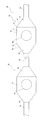
- the shape of the land portion 60 is different from the shape of the land portion 60 shown in FIG. Specifically, in the land portion 60, the connection portion 64 between the edge 65 located at the end of the inner region 61 and the edge 66 located at the end of the outer region 62 forms a curve. More specifically, the land portion 60 has a rounded hexagonal shape.
- the connecting portion 64 between the edge 65 and the edge 66 may form a continuous curve, that is, a smoother curve.
- the edge 65 and the edge 66 may form an arc.
- the shape of land portion 60 is different from the shape of land portion 60 shown in FIG. Specifically, the land part 60 has an elliptical shape.
- the land portion 60 has a rectangular shape.
- the edge 160 located at the end of the land portion 60 in the substrate width direction and the edge 163 located at the end of the wiring portion 63 in the substrate width direction form a straight line.
- 17 to 20 are diagrams showing modifications of the FPC in the wiring board according to the first embodiment of the present invention.
- the shape of FPC land portion 70 is different from the shape of FPC land portion 70 shown in FIG. Specifically, in the FPC land portion 70, the connecting portion 74 between the edge 75 located at the end of the inner region 71 and the edge 76 located at the end of the outer region 62 forms a curve. More specifically, the FPC land portion 70 has a rounded hexagonal shape.
- the connecting portion 74 between the edge 75 and the edge 76 may form a continuous curve, that is, a smoother curve.
- the edge 65 and the edge 66 may form an arc.
- the shape of the FPC land portion 70 is different from the shape of the FPC land portion 70 shown in FIG. Specifically, the FPC land portion 70 has an elliptical shape.
- the FPC land portion 70 has a rectangular shape.
- the edge 170 located at the end of the FPC land portion 70 in the substrate width direction and the edge 173 located at the end of the FPC wiring portion 73 in the substrate width direction form a straight line.
- the FPC 79 and the reinforcing plate 89 are fixed by the in-substrate adhesive layer 58.
- the present invention is not limited to this.
- the FPC 79 and the reinforcing plate 89 may be fixed by screwing.
- the wiring board 69 is configured to be fixed to the base portion 38 by the base adhesive layer 59.
- the present invention is not limited to this.
- the wiring board 69 may be configured to be fixed to the base portion 38 by screwing.
- the solar cell element becomes high temperature. Since the heat of the solar cell element is transmitted to the receiver substrate on which the solar cell element is mounted, the receiver substrate may thermally expand.
- the receiver substrate when the receiver substrate is thermally expanded in a state where it is adhered to the surface on which the receiver substrate is placed, the receiver substrate is easily peeled off from the surface.
- the portion of the receiver substrate where the solar cell element is mounted peels from the surface, the position of the solar cell element may be out of the focus of the lens, and the power generation efficiency of the solar cell element may be reduced.
- the power generation module according to the first embodiment of the present invention includes a power generation unit 30 and a wiring board 69.
- the power generation unit 30 includes a power generation element 19.
- the wiring board 69 includes a reinforcing plate 89 and an FPC 79 provided on the reinforcing plate 89.
- the power generation unit 30 is mounted on the FPC land unit 70 in the FPC 79.
- the FPC wiring part 73 is connected to the FPC land part 70.
- the width Wf3 of the FPC wiring portion 73 is smaller than the width Wf0 of the FPC land portion 70.
- the FPC wiring portion 73 can be bent more easily than the FPC land portion 70 to the wiring board 69 having a certain degree of flexibility.
- the FPC wiring portion 73 absorbs the expansion in the extending direction.
- deformation and displacement of the FPC land portion 70 can be prevented.
- the position of the power generation unit 30 is prevented from deviating from the focus of the lens. be able to.
- the power generation module according to the first embodiment of the present invention it is possible to suppress a decrease in power generation efficiency due to the influence of heat.
- the FPC land portion 70 has a length Lf1 along the extending direction of the wiring board 69.
- the FPC wiring portion 73 has a length Lf3 along the extending direction of the wiring board 69.
- the length Lf3 of the FPC wiring portion 73 is larger than the length Lf1 of the FPC land portion 70.
- Such a configuration makes it possible to bend the FPC wiring portion 73 more easily than the FPC land portion 70, so that the position of the power generation portion 30 can be more reliably prevented from being out of focus of the lens.
- the length Lf3 of the FPC wiring portion 73 is larger than 100% of the length Lf1 of the FPC land portion 70 and not more than 600%.
- the width Wf3 of the FPC wiring portion 73 is 0.1% or more and 50% or less of the width Wf0 of the FPC land portion 70.
- the width Wf3 of the FPC wiring portion 73 can be reduced with reference to the width Wf0 of the FPC land portion 70, so that the FPC wiring portion 73 is more easily bent than the FPC land portion 70. Can do. Further, the width Wf3 of the FPC wiring portion 73 can be increased to such an extent that the strength of the FPC wiring portion 73 does not matter.
- the FPC land portion 70 has an inner region 71 and an outer region 72.
- Inner region 71 has a width Wf1.
- the outer region 72 is located at at least one end in the length direction of the FPC land portion 70, is connected to the inner region 71, and has a width Wf2.
- the width Wf2 of the outer region 72 is smaller than the width Wf1 of the inner region 71 and larger than the Wf3 width of the FPC wiring portion 73.
- heat transferred from the power generation unit 30 to the inner region 71 can be efficiently released to the FPC wiring unit 73 via the outer region 72.
- the outer regions 72 are located at both ends of the FPC land portion 70 in the length direction.
- the width Wf2 of the outer region 72 is smaller than the width Wf1 of the inner region 71 and larger than the Wf3 width of the FPC wiring portion 73.
- the heat in the inner region 71 can be released to both FPC wiring portions 73 connected to the outer regions 72.
- the width Wf2 of the outer region 72 becomes smaller as it approaches the FPC wiring part 73 from the inner region 71.
- the heat in the outer region 72 can be efficiently released to the FPC wiring portion 73.
- the outer region 72 has a length Lf12 along the extending direction of the wiring board 69.
- the relationship between the width Wf2 of the outer region 72 and the length Lf12 of the outer region 72 satisfies the following expression. 0 ⁇ (Lf12 / Wf2) ⁇ 10
- the heat in the outer region 72 can be released to the FPC wiring portion 73 more efficiently.
- the power generation unit 30 is arranged such that the central portion of the power generation unit 30 is included in the inner region 71 in plan view from above the wiring board 69. .
- the power generation unit 30 can be arranged at a certain distance from the FPC wiring unit 73, so that the position of the power generation unit 30 is more reliably shifted due to the influence of the FPC wiring unit 73 being bent. Can be prevented.
- the area Sf1 of the FPC land portion 70 is 20% or more and 1000% or less of the area of the FPC wiring portion 73.
- the land reinforcing portion 80 in the reinforcing plate 89 is fixed to the FPC land portion 70.
- the wiring reinforcing part 83 is fixed to the FPC wiring part 73.
- the width Ws3 of the wiring reinforcing portion 83 is smaller than the width Ws0 of the land reinforcing portion 80.
- the FPC wiring portion 73 can be bent more easily than the FPC land portion 70.
- the reinforcing plate 89 is bonded to the base portion 38 by the base adhesive layer 59.
- the land adhesion region 50 in the base adhesive layer 59 adheres the land reinforcing portion 80 to the base portion 38.
- the wiring adhesion region 53 adheres the wiring reinforcing portion 83 to the base portion 38.
- the width Wa3 of the wiring adhesion region 53 is smaller than the width Wa0 of the land adhesion region 50.
- the wiring reinforcing portion 83 is more easily separated from the base portion 38 than the land reinforcing portion 80.
- the wiring reinforcing portion 83 and the FPC wiring portion 73 in a fixed state are connected to each other.
- the bending and peeling of the FPC land portion 70 can be prevented by bending while peeling from the base portion 38 so as to absorb the expansion in the extending direction.
- the outer region 72 is located at at least one end in the length direction of the FPC land portion 70 and is connected to the inner region 71, and It has a width Wf2.
- the width Wf1 of the inner region 71 is larger than the width Wf2 of the outer region 72.
- the edge 75 of the inner region 71 is located at the end of the inner region 71 in the width direction of the FPC land portion 70.
- the edge 76 of the outer region 72 is connected to the edge 75 of the inner region 71 and is located at the end of the outer region 72 in the width direction of the FPC land portion 70.
- the angle formed by the edge 75 and the edge 76 is greater than 90 degrees and 170 degrees or less.
- the corners of the FPC land portion 70 are obtuse, for example, when the FPC 79 and the reinforcing plate 89 in the wiring board 69 are bonded, the corners of the FPC land portion 70 due to the influence of dew condensation or the like. The peeling between the FPC 79 and the reinforcing plate 89 can be suppressed.
- the land portion 60 has a shape in which the power generation unit 30 is mounted on the land portion 60.
- the width Wb3 of the wiring part 63 is smaller than the width Wb0 of the land part 60.
- the land part 60 and the wiring part 63 include a reinforcing plate 89 made of metal and a flexible printed circuit board provided on the reinforcing plate 89.
- the land portion 60 has an inner region 61 and an outer region 62.
- Inner region 61 has a width Wb1.
- the outer region 62 is located at least at one end in the length direction of the land portion 60, is connected to the inner region 61, and has a width Wb2.
- the width Wb1 of the inner region 61 is larger than the width Wb2 of the outer region 62.
- the edge 65 of the inner region 61 is located at the end of the inner region 61 in the width direction of the land portion 60.
- the edge 66 of the outer region 62 is connected to the edge of the inner region 61 and is located at the end of the outer region 62 in the width direction of the land portion 60.
- the angle formed by the edge 65 of the inner region 61 and the edge 66 of the outer region 62 is greater than 90 degrees and 170 degrees or less.
- the wiring board according to the first embodiment of the present invention it is possible to suppress a decrease in power generation efficiency due to the influence of condensation or the like.
- connection portion between the edge 75 of the inner region 71 and the edge 76 of the outer region 72 forms a curve.
- the configuration in which the FPC land portion 70 is rounded to reduce the corners can more reliably prevent the FPC 79 and the reinforcing plate 89 from being peeled off due to the influence of condensation.
- connection portion between the edge 75 of the inner region 71 and the edge 76 of the outer region 72 forms a continuous curve.
- the periphery of the FPC land portion 70 can be made smoother, so that the separation between the FPC 79 and the reinforcing plate 89 due to the influence of condensation can be prevented more reliably.
- connection portion between the edge 65 of the inner region 61 and the edge 66 of the outer region 62 is a curve.
- the land portion 60 is rounded to reduce the corners.
- the flexible printed board 79 and the reinforcing plate 89 are bonded to each other on the wiring board 63, the flexible printed board due to the influence of condensation or the like. Peeling between 79 and the reinforcing plate 89 can be suppressed.
- the wiring board 63 and the base part 38 on which the wiring board 63 is mounted are bonded, it is possible to suppress the separation of the land part 60 from the base part 38 due to the influence of condensation or the like.
- connection portion between the edge 65 of the inner region 61 and the edge 66 of the outer region 62 forms a continuous curve.
- the present embodiment relates to a wiring board that does not include an FPC as compared to the wiring board according to the first embodiment.
- the contents other than those described below are the same as those of the photovoltaic power generation apparatus according to the first embodiment.
- the solar power generation module 10 includes a wiring board 269 instead of the wiring board 69 in the solar power generation module 10 according to the first embodiment.
- the wiring board 269 includes another type of board instead of the FPC 79 and does not include the reinforcing plate 89.
- the wiring board 269 is the same as the wiring board 69 except for the contents described below.
- FIG. 21 is a perspective view showing a state where the power generation unit is mounted on the wiring board according to the second embodiment of the present invention.
- the wiring board 269 includes a conductive portion 277 and an insulating portion 278 that covers the conductive portion 277.
- the power generation unit 30 is mounted on the land portion 260 of the wiring board 269. Specifically, the land portion 260 is provided with an opening 268. In the opening 268, since the insulating part 278 does not cover the upper side of the conductive part 277, the conductive part 277 is exposed. The power generation unit 30 is electrically connected to the conductive unit 277 at the opening 268.
- the conductive unit 277 connects, for example, the power generation unit 30 mounted on the land unit 260 and the power generation unit 30 mounted on the land unit 260 adjacent to the land unit 260 in series.
- FIG. 22 is a cross-sectional view showing a cross section taken along the line corresponding to the VI-VI line in FIG. 4 of the photovoltaic power generation module according to the second embodiment of the present invention.
- wiring board 269 is placed on the upper main surface of base portion 38.
- the power generating element 19 is housed in the package 18.
- the power generation element 19 is mounted on the wiring board 269 in a state of being housed in the package 18.
- the electrode of the power generation element 19 (not shown) is connected to the conductive portion 277 of the wiring substrate 269 via the package electrode 20 provided so as to penetrate the bottom of the package 18.
- FIG. 23 is a cross-sectional view showing a cross section taken along a line corresponding to the VII-VII line in FIG. 4 of the wiring module and the power generation unit in the solar power generation module according to the second embodiment of the present invention.
- FIG. 23 also shows, for example, an adhesive layer not shown in FIG. Specifically, referring to FIG. 23, power generation unit 30 is mounted on wiring module 49, specifically, wiring board 269 in wiring module 49. The wiring substrate 269 and the base portion 38 are bonded by the base adhesive layer 59.
- the insulating part 278 does not cover the upper side of the conductive part 277, so that a part of the conductive part 277, specifically, a part of the conductive part 277A and a part of the conductive part 277B are exposed. is doing.
- Package electrode 20A and package electrode 20B are connected to conductive portion 277A and conductive portion 277B, respectively, by soldering, for example.
- the package 18 supports the ball lens 17 at the end of its side wall, and fixes the focal point of the ball lens 17 to the power generation element 19.
- FIG. 24 is a diagram showing a wiring board according to the second embodiment of the present invention.
- FIG. 24 shows a plan view and a side view of a part of the wiring board 269.
- wiring substrate 269 includes a plurality of land portions 260 and a plurality of wiring portions 263.
- the power generation section 30 including the power generation element 19 is mounted on the land section 260.
- the wiring part 263 is electrically connected to the power generation element 19.
- the wiring portion 263 electrically connects the adjacent land portions 260, that is, the adjacent power generation units 30.
- the length Lr2 of the wiring part 263 in the extending direction of the wiring board 269 is larger than the length Lr1 of the land part 260 in the extending direction.
- the extending direction of the wiring substrate 269 is also referred to as a substrate extending direction.
- the width Wr3 of the wiring part 263 is smaller than the width Wr0 of the land part 260.
- the width Wr0 of the land portion 260 and the width Wr3 of the wiring portion 263 are respectively the direction intersecting with the substrate extending direction, specifically, for example, the length of the land portion 260 and the wiring portion 263 in the direction perpendicular to the substrate extending direction. Is the length of Hereinafter, the direction intersecting the substrate extending direction, that is, the width direction of the land portion 260 is also referred to as a substrate width direction.
- the width Wr0 of the land part 260 is, for example, 200% or more and 1000% or less of the width Wr3 of the wiring part 263.
- the length Lr1 of the land portion 260 in the substrate extending direction is larger than the width Wr0 of the land portion 260.
- the land portion 260 has an inner region 261 and two outer regions 262.
- Each outer region 262 is connected to both ends of the inner region 261 in the substrate extending direction.
- the outer region 262 is connected between the end portion of the inner region 261 in the substrate extending direction and the wiring portion 263.
- the land portion 260 may have only one outer region 262.
- the outer region 262 is connected to one end of the inner region 261 in the substrate extending direction, for example.
- the inner region 261 has a width Wr1 corresponding to the width Wr0.
- the outer region 262 has a width Wr2.
- the width Wr1 of the inner region 261 and the width Wr2 of the outer region 262 are the length of the inner region 261 and the length of the outer region 262 in the substrate width direction, respectively.
- the width Wr2 of the outer region 262 is smaller than the width Wr1 of the inner region 261.
- the width Wr2 of the outer region 262 is larger than the width Wr3 of the wiring portion 263.
- the width Wr2 of the outer region 262 continuously decreases as the wiring portion 263 to which the corresponding outer region 262 is connected is approached.
- the relationship between the width Wr2 of the outer region 262 and the length Lr12 of the outer region 262 in the substrate width direction is expressed by the following formula (4). 0 ⁇ Lr12 / Wr2 ⁇ 10 (4)
- the area Sr1 of the inner region 261 is larger than the area Sr2 of the outer region 262.
- the area Sr1 of the inner region 261 is 200% or more and 1000% or less of the area Sr2 of the outer region 262.
- the power generation unit 30 has its own central portion, specifically, The center Ce is arranged so as to be included in the inner region 261.
- the distance dr1 from the power generation unit 30 to the wiring part 263 in the board extending direction is the distance dr2 from the power generation unit 30 to the end of the land part 260 in the board width direction. Greater than.
- the wiring board 269 has an electrode for soldering the power generation unit 30.
- the electrode is an exposed portion of the conductive portion 277 in the opening 268 and is provided so as to be included in the inner region 261.
- the mounting region 31 in which the power generation unit 30 is mounted in the land portion 260 is included in the inner region 261.
- 100% of the mounting area 31 is included in the inner area 261.
- the thickness Tr3 of the wiring part 263 is 1% or more and 50% or less of the width Wr3 of the wiring part 263.
- the inner region 261 has an edge 265.
- the edge 265 is located at the end of the inner region 261 in the substrate width direction.
- the outer region 262 has an edge 266. The edge 266 is located at the end of the outer region 262 in the substrate width direction.
- the edge 265 and the edge 266 are connected to each other.
- the angle ⁇ formed by the edge 265 and the edge 266 is, for example, greater than 90 degrees and 170 degrees or less.
- a power generation module A power generation unit including a power generation element; A wiring board, The wiring board is A reinforcing plate, Including a flexible printed circuit board provided on the reinforcing plate, The flexible printed circuit board is A land part on which the power generation part is mounted; A wiring portion having a length in the extending direction of the wiring board greater than a length in the extending direction of the land portion; The width of the wiring portion is smaller than the width of the land portion,
- the power generation module is used in a solar power generation device, In the solar power generation device, the power generation module in which sunlight converged by a lens is irradiated to the power generation unit.
- a wiring board A land portion on which a power generation unit including a power generation element is mounted; With wiring part, The width of the wiring portion is smaller than the width of the land portion,
- Each of the land part and the wiring part is A reinforcing plate made of metal, Including a flexible printed circuit board provided on the reinforcing plate,
- the land portion is A first region; A second region connected to an end of the first region in the extending direction of the wiring board; The edge of the first region located at the end of the first region in the width direction of the land portion, and the second connected to the edge of the first region and located at the end of the second region in the width direction.
- the angle formed with the edge of the region is greater than 90 degrees and less than 170 degrees
- the wiring board is used in a solar power generation device,
- a wiring board A land portion on which a power generation unit including a power generation element is mounted; With wiring part, The width of the wiring portion is smaller than the width of the land portion,
- Each of the land part and the wiring part is A reinforcing plate made of metal, Including a flexible printed circuit board provided on the reinforcing plate,
- the land portion is A first region; A second region connected to an end of the first region in the extending direction of the wiring board; The edge of the first region located at the end of the first region in the width direction of the land portion, and the second connected to the edge of the first region and located at the end of the second region in the width direction.
- the connection with the edge of the region is a curve
- the wiring board is used in a solar power generation device,
Landscapes
- Engineering & Computer Science (AREA)
- Microelectronics & Electronic Packaging (AREA)
- Life Sciences & Earth Sciences (AREA)
- Sustainable Development (AREA)
- Photovoltaic Devices (AREA)
- Structure Of Printed Boards (AREA)
- Combinations Of Printed Boards (AREA)
- Manufacturing & Machinery (AREA)
- Structures For Mounting Electric Components On Printed Circuit Boards (AREA)
- Wire Bonding (AREA)
Abstract
Description
前記ランド部および前記配線部は、金属で形成された補強板と、前記補強板上に設けられたフレキシブルプリント基板とを含み、前記ランド部は、第1領域と、第2領域とを有し、前記第1領域は、第1の幅を有し、前記第2領域は、前記ランド部の長さ方向の少なくとも一端に位置し、かつ、前記第1領域と接続されており、かつ、第2の幅を有し、
前記第1の幅は、前記第2の幅より大きく、前記ランド部の幅方向における前記第1領域の端に位置する前記第1領域の縁と、前記第1領域の縁に接続され、前記幅方向における前記第2領域の端に位置する前記第2領域の縁との接続部は曲線である。
0<(Lf12/Wf2)≦10
但し、Wf2は前記第2の幅であり、Lf12は前記第2領域の前記長さである。
図1は、本発明の第1の実施の形態に係る太陽光発電装置の斜視図である。
0<Lb12/Wb2≦10 ・・・(1)
0<Lf12/Wf2≦10・・・(2)
外側領域52の幅Wa2は、内側領域51から配線接着領域53に近づくに従い連続的に小さくなる。すなわち、外側領域52の幅Wa2は、当該外側領域52と接続された配線接着領域53に近づくに従い連続的に小さくなる。
で表される。
0<La12/Wa2≦10・・・(3)
図13~図16は、本発明の第1の実施の形態に係る配線基板の変形例を示す図である。
0<(Lf12/Wf2)≦10
本実施の形態は、第1の実施の形態に係る配線基板と比べて、FPCを含まない配線基板に関する。以下で説明する内容以外は、第1の実施の形態に係る太陽光発電装置と同様である。
0<Lr12/Wr2≦10 ・・・(4)
発電モジュールであって、
発電素子を含む発電部と、
配線基板とを備え、
前記配線基板は、
補強板と、
前記補強板上に設けられたフレキシブルプリント基板とを含み、
前記フレキシブルプリント基板は、
前記発電部が実装されるランド部と、
前記配線基板の延伸方向における長さが前記ランド部の前記延伸方向における長さより大きい配線部とを有し、
前記配線部の幅は、前記ランド部の幅より小さく、
前記発電モジュールは、太陽光発電装置において用いられ、
前記太陽光発電装置において、レンズによって収束された太陽光が前記発電部へ照射される、発電モジュール。
配線基板であって、
発電素子を含む発電部が実装されるランド部と、
配線部とを備え、
前記配線部の幅は、前記ランド部の幅より小さく、
前記ランド部および前記配線部の各々は、
金属で形成された補強板と、
前記補強板上に設けられたフレキシブルプリント基板とを含み、
前記ランド部は、
第1領域と、
前記配線基板の延伸方向における前記第1領域の端部に接続された第2領域とを有し、
前記ランド部の幅方向における前記第1領域の端に位置する前記第1領域の縁と、前記第1領域の縁に接続され、前記幅方向における前記第2領域の端に位置する前記第2領域の縁とのなす角度は、90度より大きく、かつ170度以下であり、
前記配線基板は、太陽光発電装置において用いられ、
前記太陽光発電装置において、レンズによって収束された太陽光が前記発電部へ照射される、配線基板。
配線基板であって、
発電素子を含む発電部が実装されるランド部と、
配線部とを備え、
前記配線部の幅は、前記ランド部の幅より小さく、
前記ランド部および前記配線部の各々は、
金属で形成された補強板と、
前記補強板上に設けられたフレキシブルプリント基板とを含み、
前記ランド部は、
第1領域と、
前記配線基板の延伸方向における前記第1領域の端部に接続された第2領域とを有し、
前記ランド部の幅方向における前記第1領域の端に位置する前記第1領域の縁と、前記第1領域の縁に接続され、前記幅方向における前記第2領域の端に位置する前記第2領域の縁との接続部は曲線であり、
前記配線基板は、太陽光発電装置において用いられ、
前記太陽光発電装置において、レンズによって収束された太陽光が前記発電部へ照射される、配線基板。
12 太陽光発電パネル
13 太陽方向センサ
14 フレーム部
17 ボールレンズ
18 パッケージ
19 発電素子
20,20A,20B パッケージ電極
25 集光部
26 フレネルレンズ
27 壁部
29 発電モジュール
30,30P1,30P2,30Q1,30Q2,30R1,30R2 発電部
31 実装領域
32,32A,32B,32C,32D,32E,32F,32G,32H,32I,32J 帯状基板
33,33H,33I,33J,33K,33L,33M,33N,33O,33P 連結部
38 ベース部
39 リード線
40 架台
42A,42B 素子電極
46 土台
48 支柱
49 配線モジュール
50 ランド接着領域
51,61,71,261 内側領域
52,62,72,262 外側領域
53 配線接着領域
58 基板内接着層
59 ベース接着層
60,260 ランド部
63,263 配線部
64,74 接続部
65,66,75,76,160,163,170,173,265,266 縁
68,268 開口部
69,269 配線基板
70 FPCランド部
73 FPC配線部
77,77A,77B,277,277A,277B 導電部
78,278 絶縁部
79 FPC
80 ランド補強部
83 配線補強部
89 補強板
90 機能部
101 太陽光発電装置
Cc,Ce 中心
FL 受光面
Claims (18)
- 発電素子を含む発電部と、
配線基板とを備え、
前記配線基板は、
補強板と、
前記補強板上に設けられたフレキシブルプリント基板とを含み、
前記フレキシブルプリント基板は、
前記発電部が実装されるFPCランド部と、
前記FPCランド部に接続されたFPC配線部とを有し、
前記FPC配線部の幅は、前記FPCランド部の幅より小さい、発電モジュール。 - 前記FPCランド部は、前記配線基板の延伸方向に沿った長さを有し、
前記FPC配線部は、前記配線基板の延伸方向に沿った長さを有し、
前記FPC配線部の前記長さは、前記FPCランド部の前記長さより大きい、請求の範囲第1項に記載の発電モジュール。 - 前記FPC配線部の前記長さは、前記FPCランド部の前記長さの100%より大きく、かつ600%以下である、請求の範囲第2項に記載の発電モジュール。
- 前記FPC配線部の幅は、前記FPCランド部の幅の0.1%以上であり、かつ50%以下である、請求の範囲第1項から第3項のいずれか1項に記載の発電モジュール。
- 前記FPCランド部は、第1領域と、第2領域とを有し、
前記第1領域は、第1の幅を有し、
前記第2領域は、前記FPCランド部の長さ方向の少なくとも一端に位置し、かつ、前記第1領域と接続されており、かつ、第2の幅を有し、
前記第2の幅は、前記第1の幅より小さく、かつ、前記FPC配線部の幅より大きい、請求の範囲第1項から第4項のいずれか1項に記載の発電モジュール。 - 前記FPCランド部は、第1領域と、第2領域とを有し、
前記第1領域は、第1の幅を有し、
前記第2領域は、前記FPCランド部の長さ方向の両端に位置し、かつ、前記第1領域と接続されており、かつ、第2の幅を有し、
前記第2の幅は、前記第1の幅より小さく、かつ、前記FPC配線部の幅より大きい、請求の範囲第1項から第4項のいずれか1項に記載の発電モジュール。 - 前記第2の幅は、前記第1領域から前記FPC配線部に近づくに従い小さくなる、請求の範囲第5項または第6項に記載の発電モジュール。
- 前記第2領域は、前記配線基板の延伸方向に沿った長さを有し、
前記第2の幅と前記第2領域の前記長さとの関係は以下の式を満たす、請求の範囲第5項から第7項のいずれか1項に記載の発電モジュール。
0<(Lf12/Wf2)≦10
但し、Wf2は前記第2の幅であり、Lf12は前記第2領域の前記長さである。 - 前記配線基板の上方からの平面視において、前記発電部の中央部が前記第1領域に含まれるように前記発電部が配置される、請求の範囲第5項から第8項のいずれか1項に記載の発電モジュール。
- 前記FPCランド部の面積は、前記FPC配線部の面積の20%以上であり、かつ1000%以下である、請求の範囲第1項から第9項のいずれか1項に記載の発電モジュール。
- 前記補強板は、
前記FPCランド部に固定されたランド補強部と、
前記FPC配線部に固定された配線補強部とを有し、
前記配線補強部の幅は、前記ランド補強部の幅より小さい、請求の範囲第1項から第10項のいずれか1項に記載の発電モジュール。 - 前記補強板は、接着層によりベース部に接着され、
前記接着層は、
前記ランド補強部を前記ベース部に接着するランド接着領域と、
前記配線補強部を前記ベース部に接着する配線接着領域とを有し、
前記配線接着領域の幅は、前記ランド接着領域の幅より小さい、請求の範囲第11項に記載の発電モジュール。 - 前記FPCランド部は、第1領域と、第2領域とを有し、
前記第1領域は、第1の幅を有し、
前記第2領域は、前記FPCランド部の長さ方向の少なくとも一端に位置し、かつ、前記第1領域と接続されており、かつ、第2の幅を有し、
前記第1の幅は、前記第2の幅より大きく、
前記FPCランド部の幅方向における前記第1領域の端に位置する前記第1領域の縁と、前記第1領域の縁に接続され、前記幅方向における前記第2領域の端に位置する前記第2領域の縁とのなす角度は、90度より大きく、かつ170度以下である、請求の範囲第1項から第12項のいずれか1項に記載の発電モジュール。 - 前記FPCランド部は、第1領域と、第2領域とを有し、
前記第1領域は、第1の幅を有し、
前記第2領域は、前記FPCランド部の長さ方向の少なくとも一端に位置し、かつ、前記第1領域と接続されており、かつ、第2の幅を有し、
前記第1の幅は、前記第2の幅より大きく、
前記FPCランド部の幅方向における前記第1領域の端に位置する前記第1領域の縁と、前記第1領域の縁に接続され、前記幅方向における前記第2領域の端に位置する前記第2領域の縁との接続部は曲線を形成する、請求の範囲第1項から第13項のいずれか1項に記載の発電モジュール。 - 前記第1領域の縁と前記第2領域の縁との接続部は連続的な曲線を形成する、請求の範囲第14項に記載の発電モジュール。
- 配線基板であって、前記配線基板は発電部が実装されるものであり、
前記配線基板は、ランド部と、配線部とを備え、
前記ランド部は、前記ランド部上に前記発電部が実装される形状を有し、
前記配線部の幅は、前記ランド部の幅より小さく、
前記ランド部および前記配線部は、
金属で形成された補強板と、
前記補強板上に設けられたフレキシブルプリント基板とを含み、
前記ランド部は、第1領域と、第2領域とを有し、
前記第1領域は、第1の幅を有し、
前記第2領域は、前記ランド部の長さ方向の少なくとも一端に位置し、かつ、前記第1領域と接続されており、かつ、第2の幅を有し、
前記第1の幅は、前記第2の幅より大きく、
前記ランド部の幅方向における前記第1領域の端に位置する前記第1領域の縁と、前記第1領域の縁に接続され、前記幅方向における前記第2領域の端に位置する前記第2領域の縁とのなす角度は、90度より大きく、かつ170度以下である、配線基板。 - 配線基板であって、前記配線基板は発電部が実装されるものであり、
前記配線基板は、ランド部と、配線部とを備え、
前記ランド部は、前記ランド部上に前記発電部が実装される形状を有し、
前記配線部の幅は、前記ランド部の幅より小さく、
前記ランド部および前記配線部は、
金属で形成された補強板と、
前記補強板上に設けられたフレキシブルプリント基板とを含み、
前記ランド部は、第1領域と、第2領域とを有し、
前記第1領域は、第1の幅を有し、
前記第2領域は、前記ランド部の長さ方向の少なくとも一端に位置し、かつ、前記第1領域と接続されており、かつ、第2の幅を有し、
前記第1の幅は、前記第2の幅より大きく、
前記ランド部の幅方向における前記第1領域の端に位置する前記第1領域の縁と、前記第1領域の縁に接続され、前記幅方向における前記第2領域の端に位置する前記第2領域の縁との接続部は曲線である、配線基板。 - 前記第1領域の縁と前記第2領域の縁との接続部は連続的な曲線を形成する、請求の範囲第17項に記載の配線基板。
Priority Applications (5)
| Application Number | Priority Date | Filing Date | Title |
|---|---|---|---|
| JP2016532924A JP6565912B2 (ja) | 2014-07-10 | 2015-07-06 | 発電モジュールおよび配線基板 |
| MA39683A MA39683B1 (fr) | 2014-07-10 | 2015-07-06 | Module de generation d'énergie electrique et substrat de câblage |
| CN201580037735.4A CN106663711B (zh) | 2014-07-10 | 2015-07-06 | 发电模块和配线基板 |
| AU2015288772A AU2015288772B2 (en) | 2014-07-10 | 2015-07-06 | Power Generation Module and Wiring Substrate |
| US15/325,045 US10985286B2 (en) | 2014-07-10 | 2015-07-06 | Power generation module and wiring substrate |
Applications Claiming Priority (2)
| Application Number | Priority Date | Filing Date | Title |
|---|---|---|---|
| JP2014142327 | 2014-07-10 | ||
| JP2014-142327 | 2014-07-10 |
Publications (1)
| Publication Number | Publication Date |
|---|---|
| WO2016006571A1 true WO2016006571A1 (ja) | 2016-01-14 |
Family
ID=54829518
Family Applications (4)
| Application Number | Title | Priority Date | Filing Date |
|---|---|---|---|
| PCT/JP2015/069411 Ceased WO2016006573A1 (ja) | 2014-07-10 | 2015-07-06 | 発電回路ユニット |
| PCT/JP2015/069404 Ceased WO2016006568A1 (ja) | 2014-07-10 | 2015-07-06 | 配線基板および太陽光発電装置 |
| PCT/JP2015/069407 Ceased WO2016006570A1 (ja) | 2014-07-10 | 2015-07-06 | 配線モジュール |
| PCT/JP2015/069409 Ceased WO2016006571A1 (ja) | 2014-07-10 | 2015-07-06 | 発電モジュールおよび配線基板 |
Family Applications Before (3)
| Application Number | Title | Priority Date | Filing Date |
|---|---|---|---|
| PCT/JP2015/069411 Ceased WO2016006573A1 (ja) | 2014-07-10 | 2015-07-06 | 発電回路ユニット |
| PCT/JP2015/069404 Ceased WO2016006568A1 (ja) | 2014-07-10 | 2015-07-06 | 配線基板および太陽光発電装置 |
| PCT/JP2015/069407 Ceased WO2016006570A1 (ja) | 2014-07-10 | 2015-07-06 | 配線モジュール |
Country Status (7)
| Country | Link |
|---|---|
| US (5) | US20170201208A1 (ja) |
| JP (4) | JP6551409B2 (ja) |
| CN (6) | CN106537612B (ja) |
| AU (4) | AU2015288771B2 (ja) |
| MA (4) | MA39684B1 (ja) |
| TW (5) | TWI656653B (ja) |
| WO (4) | WO2016006573A1 (ja) |
Cited By (2)
| Publication number | Priority date | Publication date | Assignee | Title |
|---|---|---|---|---|
| WO2019030989A1 (ja) * | 2017-08-07 | 2019-02-14 | 住友電気工業株式会社 | 集光型太陽光発電モジュール、集光型太陽光発電パネル、集光型太陽光発電装置、及び集光型太陽光発電モジュールの製造方法 |
| WO2019030988A1 (ja) * | 2017-08-07 | 2019-02-14 | 住友電気工業株式会社 | 集光型太陽光発電モジュール、集光型太陽光発電パネル、及び集光型太陽光発電装置 |
Families Citing this family (8)
| Publication number | Priority date | Publication date | Assignee | Title |
|---|---|---|---|---|
| JP6759778B2 (ja) | 2016-07-07 | 2020-09-23 | 住友電気工業株式会社 | 集光型太陽光発電モジュール、集光型太陽光発電装置及び水素精製システム |
| CN107453699B (zh) * | 2017-08-28 | 2024-01-23 | 江西清华泰豪三波电机有限公司 | 一种光伏组件及光伏装置 |
| US10529881B2 (en) * | 2018-03-01 | 2020-01-07 | Solaero Technologies Corp. | Interconnect member |
| WO2020004148A1 (ja) * | 2018-06-27 | 2020-01-02 | 住友電気工業株式会社 | 集光型太陽光発電モジュール及び集光型太陽光発電装置 |
| WO2020004144A1 (ja) * | 2018-06-27 | 2020-01-02 | 住友電気工業株式会社 | フレキシブルプリント配線板の原形体、フレキシブルプリント配線板の製造方法、集光型太陽光発電モジュール、及び、発光モジュール |
| CN109067346A (zh) * | 2018-07-20 | 2018-12-21 | 上海空间电源研究所 | 刚挠结合板太阳电池阵 |
| CN111609370A (zh) * | 2020-05-19 | 2020-09-01 | 田聪 | 一种基于电容传感的太阳能路灯雨天可保证亮度的装置 |
| JP2024140456A (ja) * | 2023-03-28 | 2024-10-10 | Tdk株式会社 | 回路基板 |
Citations (4)
| Publication number | Priority date | Publication date | Assignee | Title |
|---|---|---|---|---|
| JP2007019334A (ja) * | 2005-07-08 | 2007-01-25 | Mitsubishi Electric Corp | 太陽電池装置 |
| US20120279551A1 (en) * | 2003-10-20 | 2012-11-08 | Vahan Garboushian | Method of improving the efficiency of loosely packed solar cells in dense array applications |
| JP2013080760A (ja) * | 2011-10-03 | 2013-05-02 | Sumitomo Electric Ind Ltd | 集光型太陽光発電モジュール、集光型太陽光発電パネル、及び、集光型太陽光発電モジュール用フレキシブルプリント配線板 |
| JP2013084855A (ja) * | 2011-10-12 | 2013-05-09 | Sharp Corp | 集光型太陽電池モジュール及び太陽光発電システム |
Family Cites Families (19)
| Publication number | Priority date | Publication date | Assignee | Title |
|---|---|---|---|---|
| JP2001298217A (ja) * | 2000-04-13 | 2001-10-26 | Sumitomo Electric Ind Ltd | 光モジュール |
| JP2005051133A (ja) | 2003-07-31 | 2005-02-24 | Canon Inc | プリント配線基板 |
| US7550097B2 (en) | 2003-09-03 | 2009-06-23 | Momentive Performance Materials, Inc. | Thermal conductive material utilizing electrically conductive nanoparticles |
| JP4648063B2 (ja) | 2005-04-19 | 2011-03-09 | 日東電工株式会社 | カテーテル用フレキシブル配線回路基板、並びに、該フレキシブル配線回路基板を用いたカテーテル及びその製造方法 |
| US8759138B2 (en) | 2008-02-11 | 2014-06-24 | Suncore Photovoltaics, Inc. | Concentrated photovoltaic system modules using III-V semiconductor solar cells |
| KR20110053922A (ko) * | 2008-04-21 | 2011-05-24 | 스미토모 베이클리트 컴퍼니 리미티드 | 플렉시블 배선 유닛 및 전자 기기 |
| WO2010016098A1 (ja) | 2008-08-08 | 2010-02-11 | 京セミ株式会社 | 採光型太陽電池モジュール |
| WO2011043318A1 (ja) | 2009-10-05 | 2011-04-14 | 株式会社村田製作所 | 回路基板 |
| EP2362432B1 (en) * | 2010-02-25 | 2017-06-07 | Saint-Augustin Canada Electric Inc. | Solar cell assembly |
| JP5853374B2 (ja) | 2010-03-12 | 2016-02-09 | オムロン株式会社 | 照明装置 |
| JP2011210747A (ja) | 2010-03-26 | 2011-10-20 | Mitsubishi Chemicals Corp | 太陽電池モジュール及びその製造方法 |
| US8677639B2 (en) * | 2010-10-21 | 2014-03-25 | K-2 Corporation | Ski pole with inclinometer |
| JP2013012605A (ja) * | 2011-06-29 | 2013-01-17 | Sharp Corp | 集光型太陽光発電装置、および集光型太陽光発電装置の製造方法 |
| WO2013031298A1 (ja) * | 2011-08-31 | 2013-03-07 | 三洋電機株式会社 | 太陽電池モジュール及びその製造方法 |
| JP6172461B2 (ja) * | 2011-09-23 | 2017-08-02 | パナソニックIpマネジメント株式会社 | 太陽電池モジュール及び太陽電池 |
| US20130104958A1 (en) * | 2011-10-31 | 2013-05-02 | E I Du Pont De Nemours And Company | Integrated back-sheet for back contact photovoltaic module |
| JP5948899B2 (ja) | 2012-01-25 | 2016-07-06 | 住友電気工業株式会社 | 集光型太陽光発電モジュール及び集光型太陽光発電パネル |
| US9008122B2 (en) * | 2012-07-23 | 2015-04-14 | Cisco Technology, Inc. | Method and apparatus for triggering bandwidth upspeeding within an existing reservation |
| JP5643792B2 (ja) | 2012-08-10 | 2014-12-17 | 株式会社東具 | 電飾広告用のライン照明装置 |
-
2015
- 2015-07-03 TW TW104121706A patent/TWI656653B/zh not_active IP Right Cessation
- 2015-07-06 WO PCT/JP2015/069411 patent/WO2016006573A1/ja not_active Ceased
- 2015-07-06 AU AU2015288771A patent/AU2015288771B2/en not_active Ceased
- 2015-07-06 WO PCT/JP2015/069404 patent/WO2016006568A1/ja not_active Ceased
- 2015-07-06 AU AU2015288774A patent/AU2015288774B2/en not_active Ceased
- 2015-07-06 US US15/324,984 patent/US20170201208A1/en not_active Abandoned
- 2015-07-06 MA MA39684A patent/MA39684B1/fr unknown
- 2015-07-06 CN CN201580037722.7A patent/CN106537612B/zh not_active Expired - Fee Related
- 2015-07-06 CN CN201580037735.4A patent/CN106663711B/zh not_active Expired - Fee Related
- 2015-07-06 JP JP2016532923A patent/JP6551409B2/ja not_active Expired - Fee Related
- 2015-07-06 WO PCT/JP2015/069407 patent/WO2016006570A1/ja not_active Ceased
- 2015-07-06 MA MA39682A patent/MA39682B2/fr unknown
- 2015-07-06 WO PCT/JP2015/069409 patent/WO2016006571A1/ja not_active Ceased
- 2015-07-06 AU AU2015288769A patent/AU2015288769B2/en not_active Ceased
- 2015-07-06 JP JP2016532925A patent/JP6520943B2/ja not_active Expired - Fee Related
- 2015-07-06 US US15/325,034 patent/US11101395B2/en not_active Expired - Fee Related
- 2015-07-06 AU AU2015288772A patent/AU2015288772B2/en not_active Ceased
- 2015-07-06 MA MA39683A patent/MA39683B1/fr unknown
- 2015-07-06 US US15/325,045 patent/US10985286B2/en not_active Expired - Fee Related
- 2015-07-06 MA MA39681A patent/MA39681B1/fr unknown
- 2015-07-06 US US15/325,006 patent/US10680127B2/en active Active
- 2015-07-06 JP JP2016532924A patent/JP6565912B2/ja not_active Expired - Fee Related
- 2015-07-06 CN CN201580037394.0A patent/CN106537611B/zh not_active Expired - Fee Related
- 2015-07-06 JP JP2016532921A patent/JP6551408B2/ja not_active Expired - Fee Related
- 2015-07-06 CN CN201580037390.2A patent/CN106537610B/zh not_active Expired - Fee Related
- 2015-07-08 TW TW104122149A patent/TWI661569B/zh not_active IP Right Cessation
- 2015-07-08 TW TW104122150A patent/TWI658604B/zh not_active IP Right Cessation
- 2015-07-08 TW TW104122151A patent/TWI666786B/zh not_active IP Right Cessation
- 2015-07-08 TW TW104122148A patent/TWI666781B/zh not_active IP Right Cessation
- 2015-07-09 CN CN201520493611.4U patent/CN204885177U/zh not_active Expired - Fee Related
- 2015-07-09 CN CN201510400688.7A patent/CN105261661B/zh not_active Expired - Fee Related
- 2015-07-09 US US14/795,653 patent/US9923107B2/en not_active Expired - Fee Related
Patent Citations (4)
| Publication number | Priority date | Publication date | Assignee | Title |
|---|---|---|---|---|
| US20120279551A1 (en) * | 2003-10-20 | 2012-11-08 | Vahan Garboushian | Method of improving the efficiency of loosely packed solar cells in dense array applications |
| JP2007019334A (ja) * | 2005-07-08 | 2007-01-25 | Mitsubishi Electric Corp | 太陽電池装置 |
| JP2013080760A (ja) * | 2011-10-03 | 2013-05-02 | Sumitomo Electric Ind Ltd | 集光型太陽光発電モジュール、集光型太陽光発電パネル、及び、集光型太陽光発電モジュール用フレキシブルプリント配線板 |
| JP2013084855A (ja) * | 2011-10-12 | 2013-05-09 | Sharp Corp | 集光型太陽電池モジュール及び太陽光発電システム |
Cited By (7)
| Publication number | Priority date | Publication date | Assignee | Title |
|---|---|---|---|---|
| WO2019030989A1 (ja) * | 2017-08-07 | 2019-02-14 | 住友電気工業株式会社 | 集光型太陽光発電モジュール、集光型太陽光発電パネル、集光型太陽光発電装置、及び集光型太陽光発電モジュールの製造方法 |
| WO2019030988A1 (ja) * | 2017-08-07 | 2019-02-14 | 住友電気工業株式会社 | 集光型太陽光発電モジュール、集光型太陽光発電パネル、及び集光型太陽光発電装置 |
| JPWO2019030988A1 (ja) * | 2017-08-07 | 2020-08-06 | 住友電気工業株式会社 | 集光型太陽光発電モジュール、集光型太陽光発電パネル、及び集光型太陽光発電装置 |
| JPWO2019030989A1 (ja) * | 2017-08-07 | 2020-08-20 | 住友電気工業株式会社 | 集光型太陽光発電モジュール、集光型太陽光発電パネル、集光型太陽光発電装置、及び集光型太陽光発電モジュールの製造方法 |
| US11201255B2 (en) | 2017-08-07 | 2021-12-14 | Sumitomo Electric Industries, Ltd. | Concentrator photovoltaic module, concentrator photovoltaic panel, and concentrator photovoltaic apparatus |
| JP7021670B2 (ja) | 2017-08-07 | 2022-02-17 | 住友電気工業株式会社 | 集光型太陽光発電モジュール、集光型太陽光発電パネル、及び集光型太陽光発電装置 |
| JP7021671B2 (ja) | 2017-08-07 | 2022-02-17 | 住友電気工業株式会社 | 集光型太陽光発電モジュール、集光型太陽光発電パネル、集光型太陽光発電装置、及び集光型太陽光発電モジュールの製造方法 |
Also Published As
Similar Documents
| Publication | Publication Date | Title |
|---|---|---|
| JP6565912B2 (ja) | 発電モジュールおよび配線基板 | |
| US20090064994A1 (en) | Concentrating solar collector | |
| CA2680595A1 (en) | Solar cell, method for manufacturing solar cells, and electric conductor track | |
| JP6489143B2 (ja) | フレキシブルプリント基板およびフレキシブルプリント基板の固定方法 | |
| JP6123845B2 (ja) | 太陽光発電モジュール、太陽光発電装置および太陽光発電モジュールの製造方法 |
Legal Events
| Date | Code | Title | Description |
|---|---|---|---|
| 121 | Ep: the epo has been informed by wipo that ep was designated in this application |
Ref document number: 15819063 Country of ref document: EP Kind code of ref document: A1 |
|
| ENP | Entry into the national phase |
Ref document number: 2016532924 Country of ref document: JP Kind code of ref document: A |
|
| WWE | Wipo information: entry into national phase |
Ref document number: 39683 Country of ref document: MA Ref document number: 15325045 Country of ref document: US |
|
| NENP | Non-entry into the national phase |
Ref country code: DE |
|
| ENP | Entry into the national phase |
Ref document number: 2015288772 Country of ref document: AU Date of ref document: 20150706 Kind code of ref document: A |
|
| 122 | Ep: pct application non-entry in european phase |
Ref document number: 15819063 Country of ref document: EP Kind code of ref document: A1 |