WO2016006563A1 - トリポード型等速自在継手 - Google Patents
トリポード型等速自在継手 Download PDFInfo
- Publication number
- WO2016006563A1 WO2016006563A1 PCT/JP2015/069388 JP2015069388W WO2016006563A1 WO 2016006563 A1 WO2016006563 A1 WO 2016006563A1 JP 2015069388 W JP2015069388 W JP 2015069388W WO 2016006563 A1 WO2016006563 A1 WO 2016006563A1
- Authority
- WO
- WIPO (PCT)
- Prior art keywords
- roller
- diameter
- velocity universal
- universal joint
- type constant
- Prior art date
Links
- 230000002093 peripheral effect Effects 0.000 description 7
- 238000005096 rolling process Methods 0.000 description 4
- 238000005242 forging Methods 0.000 description 3
- 239000013585 weight reducing agent Substances 0.000 description 3
- 230000003247 decreasing effect Effects 0.000 description 2
- 238000006073 displacement reaction Methods 0.000 description 2
- 230000005540 biological transmission Effects 0.000 description 1
- 230000007423 decrease Effects 0.000 description 1
- 239000000446 fuel Substances 0.000 description 1
- 230000004048 modification Effects 0.000 description 1
- 238000012986 modification Methods 0.000 description 1
- 238000005549 size reduction Methods 0.000 description 1
Images
Classifications
-
- F—MECHANICAL ENGINEERING; LIGHTING; HEATING; WEAPONS; BLASTING
- F16—ENGINEERING ELEMENTS AND UNITS; GENERAL MEASURES FOR PRODUCING AND MAINTAINING EFFECTIVE FUNCTIONING OF MACHINES OR INSTALLATIONS; THERMAL INSULATION IN GENERAL
- F16D—COUPLINGS FOR TRANSMITTING ROTATION; CLUTCHES; BRAKES
- F16D3/00—Yielding couplings, i.e. with means permitting movement between the connected parts during the drive
- F16D3/16—Universal joints in which flexibility is produced by means of pivots or sliding or rolling connecting parts
- F16D3/20—Universal joints in which flexibility is produced by means of pivots or sliding or rolling connecting parts one coupling part entering a sleeve of the other coupling part and connected thereto by sliding or rolling members
- F16D3/202—Universal joints in which flexibility is produced by means of pivots or sliding or rolling connecting parts one coupling part entering a sleeve of the other coupling part and connected thereto by sliding or rolling members one coupling part having radially projecting pins, e.g. tripod joints
- F16D3/205—Universal joints in which flexibility is produced by means of pivots or sliding or rolling connecting parts one coupling part entering a sleeve of the other coupling part and connected thereto by sliding or rolling members one coupling part having radially projecting pins, e.g. tripod joints the pins extending radially outwardly from the coupling part
- F16D3/2055—Universal joints in which flexibility is produced by means of pivots or sliding or rolling connecting parts one coupling part entering a sleeve of the other coupling part and connected thereto by sliding or rolling members one coupling part having radially projecting pins, e.g. tripod joints the pins extending radially outwardly from the coupling part having three pins, i.e. true tripod joints
-
- F—MECHANICAL ENGINEERING; LIGHTING; HEATING; WEAPONS; BLASTING
- F16—ENGINEERING ELEMENTS AND UNITS; GENERAL MEASURES FOR PRODUCING AND MAINTAINING EFFECTIVE FUNCTIONING OF MACHINES OR INSTALLATIONS; THERMAL INSULATION IN GENERAL
- F16C—SHAFTS; FLEXIBLE SHAFTS; ELEMENTS OR CRANKSHAFT MECHANISMS; ROTARY BODIES OTHER THAN GEARING ELEMENTS; BEARINGS
- F16C23/00—Bearings for exclusively rotary movement adjustable for aligning or positioning
- F16C23/06—Ball or roller bearings
- F16C23/08—Ball or roller bearings self-adjusting
- F16C23/082—Ball or roller bearings self-adjusting by means of at least one substantially spherical surface
-
- F—MECHANICAL ENGINEERING; LIGHTING; HEATING; WEAPONS; BLASTING
- F16—ENGINEERING ELEMENTS AND UNITS; GENERAL MEASURES FOR PRODUCING AND MAINTAINING EFFECTIVE FUNCTIONING OF MACHINES OR INSTALLATIONS; THERMAL INSULATION IN GENERAL
- F16D—COUPLINGS FOR TRANSMITTING ROTATION; CLUTCHES; BRAKES
- F16D1/00—Couplings for rigidly connecting two coaxial shafts or other movable machine elements
- F16D1/06—Couplings for rigidly connecting two coaxial shafts or other movable machine elements for attachment of a member on a shaft or on a shaft-end
-
- F—MECHANICAL ENGINEERING; LIGHTING; HEATING; WEAPONS; BLASTING
- F16—ENGINEERING ELEMENTS AND UNITS; GENERAL MEASURES FOR PRODUCING AND MAINTAINING EFFECTIVE FUNCTIONING OF MACHINES OR INSTALLATIONS; THERMAL INSULATION IN GENERAL
- F16C—SHAFTS; FLEXIBLE SHAFTS; ELEMENTS OR CRANKSHAFT MECHANISMS; ROTARY BODIES OTHER THAN GEARING ELEMENTS; BEARINGS
- F16C2361/00—Apparatus or articles in engineering in general
- F16C2361/41—Couplings
-
- F—MECHANICAL ENGINEERING; LIGHTING; HEATING; WEAPONS; BLASTING
- F16—ENGINEERING ELEMENTS AND UNITS; GENERAL MEASURES FOR PRODUCING AND MAINTAINING EFFECTIVE FUNCTIONING OF MACHINES OR INSTALLATIONS; THERMAL INSULATION IN GENERAL
- F16D—COUPLINGS FOR TRANSMITTING ROTATION; CLUTCHES; BRAKES
- F16D3/00—Yielding couplings, i.e. with means permitting movement between the connected parts during the drive
- F16D3/16—Universal joints in which flexibility is produced by means of pivots or sliding or rolling connecting parts
- F16D3/20—Universal joints in which flexibility is produced by means of pivots or sliding or rolling connecting parts one coupling part entering a sleeve of the other coupling part and connected thereto by sliding or rolling members
- F16D3/202—Universal joints in which flexibility is produced by means of pivots or sliding or rolling connecting parts one coupling part entering a sleeve of the other coupling part and connected thereto by sliding or rolling members one coupling part having radially projecting pins, e.g. tripod joints
- F16D2003/2026—Universal joints in which flexibility is produced by means of pivots or sliding or rolling connecting parts one coupling part entering a sleeve of the other coupling part and connected thereto by sliding or rolling members one coupling part having radially projecting pins, e.g. tripod joints with trunnion rings, i.e. with tripod joints having rollers supported by a ring on the trunnion
-
- Y—GENERAL TAGGING OF NEW TECHNOLOGICAL DEVELOPMENTS; GENERAL TAGGING OF CROSS-SECTIONAL TECHNOLOGIES SPANNING OVER SEVERAL SECTIONS OF THE IPC; TECHNICAL SUBJECTS COVERED BY FORMER USPC CROSS-REFERENCE ART COLLECTIONS [XRACs] AND DIGESTS
- Y10—TECHNICAL SUBJECTS COVERED BY FORMER USPC
- Y10S—TECHNICAL SUBJECTS COVERED BY FORMER USPC CROSS-REFERENCE ART COLLECTIONS [XRACs] AND DIGESTS
- Y10S464/00—Rotary shafts, gudgeons, housings, and flexible couplings for rotary shafts
- Y10S464/904—Homokinetic coupling
- Y10S464/905—Torque transmitted via radially extending pin
Definitions
- the present invention relates to a sliding tripod type constant velocity universal joint used for power transmission in automobiles, industrial machines and the like.
- the tripod type constant velocity universal joint 51 has three track grooves 53 extending in the axial direction at the three-way positions in the circumferential direction, and opposite side walls of the track grooves 53.
- An outer joint member 52 having a roller guide surface 54 formed thereon, a tripod member 60 having a trunnion journal 62 projecting radially from a circumferential trisection position of the trunnion body 61, and around each trunnion journal 62
- a spherical roller 70 rotatably mounted via a plurality of needle rollers 72, and this spherical roller 70 is accommodated in the track groove 53 of the outer joint member 52, and the outer spherical surface of the spherical roller 70 is the track groove 53. It is guided by roller guide surfaces 54 formed on both side walls (see Patent Document 1).
- the tripod type constant velocity universal joint 51 described in Patent Document 1 is light and compact by reducing the outer diameter of the outer joint member in consideration of strength and durability. With this tripod type constant velocity universal joint 51, focusing on the balance between strength and durability, the balance of strength and durability is balanced with the aim of balancing strength and durability. The dimension ratio has been revised. However, in recent years, demands for improving the fuel efficiency of automobiles are increasing, and further reduction in weight of constant velocity universal joints, which is one of automobile parts, is strongly desired. This demand cannot be reached by the tripod type constant velocity universal joints proposed so far.
- an object of the present invention is to provide a lightweight and compact tripod type constant velocity universal joint having a dimension setting that is qualitatively different from that of the prior art while maintaining strength and life.
- the tripod type constant velocity universal joint has the following seven items as basic dimensional ratios.
- Shaft diameter d / Roller guide surface pitch circle diameter PCD (d / PCD) (2) trunnion trunk diameter dr / trunnion outer diameter SDj (dr / SDj) (3) Small inner diameter D2 / large inner diameter D1 (D2 / D1) of the outer joint member (4) Roller width Ls / roller outer diameter Ds (Ls / Ds) (5) Trunnion journal diameter Dj / roller outer diameter Ds (Dj / Ds) (6) Trunnion journal diameter Dj / shaft diameter d (Dj / d) (7) Needle roller length Ln / trunnion journal diameter Dj (Ln / Dj)
- tripod type constant velocity universal joints are designed mainly with strength (torsional strength).
- the strength is usually uniquely determined by the minimum outer diameter of the shaft, and then the strength of the tripod member or the strength of the spherical roller is considered. Therefore, the tripod member or the spherical roller is set to have a strength higher than that of the shaft.
- the strength of the tripod member is related to the strength of the root of the trunnion journal in the direction of torque load.
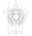
- the root portion of the trunnion journal in the torque load direction is a root portion of the trunnion journal located on a plane including the axes of the three trunnion journals. Since the minimum thickness (t in FIG. 2) of the trunnion body at the root of the trunnion journal in the torque load direction increases by increasing the diameter of the trunnion journal, the strength of the root of the trunnion journal increases.
- the present inventor is based on the fact that the strength of the tripod type constant velocity universal joint is set to be equal to or higher than the shaft strength among the above-mentioned situations, but the members that need to ensure strength next are the tripod member, the spherical roller, and the like. Therefore, attention was paid to the dimension setting on the premise of securing the strength of the tripod member and the spherical roller.
- the shaft diameter d determined for each joint size is fixed, and the pitch circle diameter PCD of the roller guide surface is conventionally set while ensuring the minimum thickness of the trunnion barrel at the root of the trunnion journal in the torque load direction.
- the technology is to reduce the size by setting different sizes.
- the pitch circle diameter PCD of the roller guide surface is a pitch circle diameter connecting the centers (O1 in FIG. 2) of the roller guide surface.
- the shaft diameter d is the large diameter of the spline formed on the trunnion body 8 of the tripod member 3.
- the width Ls of the spherical roller is reduced, the outer diameter of the outer joint member is reduced, the value of the small inner diameter D2 / large inner diameter D1 (D2 / D1) is increased, and the unevenness of the small inner diameter D2 and the large inner diameter D1 is reduced. . Since the irregularities of the small inner diameter D2 and the large inner diameter D1 are reduced, it is advantageous in terms of weight reduction and forging workability.
- the present invention is spline-fitted to a shaft and an outer joint member in which a track groove extending in the axial direction is formed at a three-fold position in the circumferential direction so that torque can be transmitted.
- a tripod member composed of a trunnion body and a trunnion journal projecting radially from a circumferential trisection position of the trunnion body, and rotatable around each trunnion journal via a plurality of needle rollers
- a tripod type in which the spherical roller is accommodated in the track groove, and the outer spherical surface of the spherical roller is guided by roller guide surfaces formed on both side walls of the track groove.
- a large inner diameter connecting the radially outer ends of the roller guide surfaces is D1
- the radially inner ends of the roller guide surfaces are D1.
- the ratio D2 / D1 of D2 and D1 is 0.73 to 0.80, and the large spline diameter formed on the trunnion body of the tripod member is d, and the roller guide surface
- the pitch circle diameter of PCD is PCD
- the ratio d / PCD of d and PCD is 0.60 or more.
- the size can be further reduced by about one size (about 4%) with respect to the conventional tripod type constant velocity universal joint having the same shaft diameter and the outer diameter being reduced.
- the ratio d / PCD of d and PCD is 0.62 to 0.70. Thereby, further light weight and size reduction can be achieved.
- the width of the spherical roller is Ls and the outer diameter of the spherical roller is Ds
- the ratio Ls / Ds of Ls to Ds is 0.20 to 0.27, so that the outer diameter of the outer joint member is Can be kept small.
- the ratio Ln / Dj of Ln / Dj is 0.40 to 0.47, so that the strength of the trunnion As well as sufficient durability.
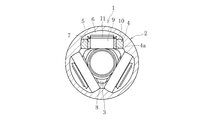
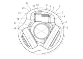
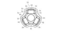
- FIG. 1a is a cross-sectional view of a tripod constant velocity universal joint according to an embodiment of the present invention
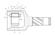
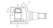
- FIG. 1b is a vertical cross-sectional view.
- a tripod type constant velocity universal joint 1 according to the present embodiment has an outer joint member 2, a tripod member 3 as an inner joint member, a spherical roller 4, and a needle roller 5 as a rolling element.
- the outer joint member 2 is in the shape of a hollow cup having three track grooves 6 extending in the axial direction at circumferentially equally divided positions on the inner periphery thereof.
- Roller guide surfaces 7 are formed on opposite side walls of each track groove 6.
- the roller guide surface 7 is formed of a part of a cylindrical surface, that is, a partial cylindrical surface.
- the tripod member 3 includes a trunnion body 8 and a trunnion journal 9, and three trunnion journals 9 are formed so as to protrude in the radial direction from the circumferentially divided position of the trunnion body 8.
- Each trunnion journal 9 includes a cylindrical outer peripheral surface 10 and an annular retaining ring groove 11 formed near the shaft end.
- a spherical roller 4 is rotatably mounted around a cylindrical outer peripheral surface 10 of the trunnion journal 9 via a plurality of needle rollers 5.
- the cylindrical outer peripheral surface 10 of the trunnion journal 9 forms the inner raceway surface of the needle roller 5.
- the inner peripheral surface 4 a of the spherical roller 4 is cylindrical and forms the outer raceway surface of the needle roller 5.
- a retaining ring 13 is attached to a retaining ring groove 11 formed near the shaft end of the trunnion journal 9 via an outer washer 12.
- the needle roller 5 is restricted from moving in the axial direction of the trunnion journal 9 by the root step portion of the trunnion journal 9 and the outer washer 12.
- the outer washer 12 includes a disk portion 12 a extending in the radial direction of the trunnion journal 9 and a cylindrical portion 12 b extending in the axial direction of the trunnion journal 9.
- the cylindrical portion 12 b of the outer washer 12 has an outer diameter smaller than the inner peripheral surface 4 a of the spherical roller 4, and the outer end 12 c of the cylindrical portion 12 b viewed in the radial direction of the tripod member 3 is the inner periphery of the spherical roller 4. It has a larger diameter than the surface 4a. Therefore, the spherical roller 4 can move in the axial direction of the trunnion journal 9 and is prevented from falling off by the end 12c.
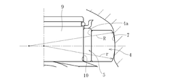
- the spherical roller 4 rotatably mounted on the trunnion journal 9 of the trunnion member 3 is guided rotatably on the roller guide surface 7 of the track groove 6 of the outer joint member 2.
- Angular contact has a contact angle and contacts at two points.
- the circular contact contacts at one point as shown in FIG.
- the contact rate R / r is about 1.02 to 1.15.
- the outer joint member 2 has an inner diameter composed of a large inner diameter portion having an inner diameter D1 and a smaller inner diameter portion having an inner diameter D2 that appear alternately in the circumferential direction.
- the tripod member 3 incorporated in the outer joint member 2 has a spline hole having a spline large diameter d formed in the trunnion body portion 8, and the cylindrical outer peripheral surface 10 of the trunnion journal 9 has an outer diameter Dj.
- the outer diameter of the spherical roller 4 is Ds
- the width of the spherical roller 4 is Ls.
- Needle roller 5 has a length Ln.
- the pitch circle diameter of the roller guide surface 7 is PCD.
- the characteristic configuration of the tripod type constant velocity universal joint 1 according to the present embodiment is dimensionally different from the prior art in order to achieve the ultimate light weight and compactness while maintaining the strength and life. ing.
- the strength of the tripod type constant velocity universal joint 1 is basically set to be equal to or higher than the shaft strength, but the members that need to be secured next are the tripod member 3 and the spherical roller 4.
- the tripod type constant velocity universal joint 1 is dimensioned on the assumption that the strength of the tripod member 3 and the spherical roller 4 is ensured.
- the basic guideline is that the shaft diameter d determined for each joint size is constant, and the pitch of the roller guide surface 7 is secured while ensuring the minimum thickness t of the trunnion body 8 at the root 9a of the trunnion journal 9 in the torque load direction.
- the circle diameter PCD is reduced with a dimensional setting different from the prior art.
- the outer diameter of the outer joint member 2 is also increased. Therefore, the outer diameter of the outer joint member 2 is reduced by reducing the width Ls of the spherical roller 4.
- the outer diameter of the outer joint member 2 is reduced, the small inner diameter D2 / large inner diameter D1 (D2 / D1) is increased, and the unevenness between the small inner diameter D2 and the large inner diameter D1 is reduced.
- the outer diameter Dj of the trunnion journal 9 is increased, so that the number of needle rollers 5 to be loaded is increased and the surface pressure is decreased.
- the roller length Ln is shortened.
- the tripod type constant velocity universal joint according to the present embodiment has dimensions (1), (3), (4), (6), and (7) that are qualitatively different from those in the prior art. .
- Table 1 shows the dimensional ratio of this embodiment.
- the ratio d / PCD between the spline large diameter (shaft diameter) d and the PCD of the roller guide surface 7 is 60% or more, a significant reduction in weight and size can be achieved. More preferably, it is in the range of 62% to 70%.
- the shaft diameter d is determined from the allowable load capacity and is constant for each joint size. Therefore, this ratio d / PCD serves as a base for reducing the outer diameter of the outer joint member.
- the ratio d / PCD is 60% or more, The range of 62% to 70% could not be reached.
- the ratio D2 / D1 between the small inner diameter D2 and the large inner diameter D1 of the outer joint member 2 was 73% to 80%.
- the small inner diameter D2 of the outer joint member 2 is set in consideration of a roller width Ls and a roller outer diameter Ds of a spherical roller 4 to be described later, while being able to ensure an operation region without interference with the shaft diameter d and the trunnion body diameter dr. Yes.
- the large inner diameter D1 is determined from the pitch circle diameter PCD of the roller guide surface 7, the trunnion outer diameter SDj, the roller width Ls of the spherical roller 4, and the roller outer diameter Ds.
- the ratio D2 / D1 between the small inner diameter D2 and the large inner diameter D1 is the most characteristic of this embodiment.
- the ratio D2 / D1 between the small inner diameter D2 and the large inner diameter D1 of the outer joint member 2 is reduced, and the irregularities of the small inner diameter D2 and the large inner diameter D1 are uneven. Since it is reduced, it is superior in weight reduction and forging processability.
- the ratio Ls / Ds between the roller width Ls of the spherical roller 4 and the roller outer diameter Ds was 20% to 27%.
- the upper limit is less than 27%. Accordingly, the outer diameter Ds of the spherical roller occupying the circumferential direction on the PCD of the roller guide surface 7 can be increased to the limit, and the contact ellipse between the spherical roller 4 and the roller guide surface 7 when a predetermined torque is applied.
- the length and contact surface pressure can be kept within an allowable range.
- the ratio d / PCD of the shaft diameter d and the PCD of the roller guide surface 7 described above can be greatly increased and the outer diameter of the outer joint member can be reduced.
- the ratio Ln / Dj between the roller length Ln of the needle roller 5 and the outer diameter Dj of the trunnion journal 10 was 40% to 47%.
- the upper limit is less than 47%.
- the ratio dr / SDj between the diameter dr of the trunnion cylinder 8 and the trunnion outer diameter SDj and the ratio Dj / Ds between the outer diameter Dj of the trunnion journal 10 and the outer diameter Ds of the spherical roller 4 have been conventionally considered in consideration of strength and durability.
- the dimensions are the same as the technology.
- FIG. 4 is a cross-sectional view of the tripod type constant velocity universal joint according to the embodiment of the present invention and the prior art as compared to the left and right. It will be understood how the tripod type constant velocity universal joint according to the present embodiment shown on the right side of the figure is lighter and more compact than the prior art.
- the root portion 9a of the trunnion journal 9 of the tripod member 3 is directly the guide collar of the needle roller 5.
- the present invention is not limited to this, and a shoulder portion is provided at the root portion.
- a separate inner washer may be interposed between the roller ends.
Landscapes
- Engineering & Computer Science (AREA)
- General Engineering & Computer Science (AREA)
- Mechanical Engineering (AREA)
- Rolling Contact Bearings (AREA)
Priority Applications (2)
| Application Number | Priority Date | Filing Date | Title |
|---|---|---|---|
| US15/319,241 US10302143B2 (en) | 2014-07-08 | 2015-07-06 | Tripod type constant velocity universal joint |
| EP15818289.9A EP3168490B1 (en) | 2014-07-08 | 2015-07-06 | Tripod-type constant-velocity universal joint |
Applications Claiming Priority (2)
| Application Number | Priority Date | Filing Date | Title |
|---|---|---|---|
| JP2014140504A JP6328505B2 (ja) | 2014-07-08 | 2014-07-08 | トリポード型等速自在継手 |
| JP2014-140504 | 2014-07-08 |
Publications (1)
| Publication Number | Publication Date |
|---|---|
| WO2016006563A1 true WO2016006563A1 (ja) | 2016-01-14 |
Family
ID=53801702
Family Applications (1)
| Application Number | Title | Priority Date | Filing Date |
|---|---|---|---|
| PCT/JP2015/069388 WO2016006563A1 (ja) | 2014-07-08 | 2015-07-06 | トリポード型等速自在継手 |
Country Status (6)
Families Citing this family (8)
| Publication number | Priority date | Publication date | Assignee | Title |
|---|---|---|---|---|
| JP6328505B2 (ja) * | 2014-07-08 | 2018-05-23 | Ntn株式会社 | トリポード型等速自在継手 |
| ES2715451T3 (es) | 2015-06-03 | 2019-06-04 | Weidplas Gmbh | Componente |
| CN106594098B (zh) * | 2017-01-24 | 2019-02-01 | 杭州通绿机械有限公司 | 一种小型化三球销式移动节的优化设计方法 |
| JP7211261B2 (ja) * | 2019-05-17 | 2023-01-24 | 株式会社ジェイテクト | トリポード型等速継手 |
| CN112240354B (zh) * | 2019-07-19 | 2021-12-07 | 上海纳铁福传动系统有限公司 | 一种高强度紧凑型三枢轴式万向节 |
| JP7680864B2 (ja) * | 2021-03-24 | 2025-05-21 | Ntn株式会社 | トリポード型等速自在継手 |
| JP7680914B2 (ja) * | 2021-09-03 | 2025-05-21 | Ntn株式会社 | トリポード型等速自在継手 |
| CN116984848B (zh) * | 2023-09-27 | 2023-12-26 | 万向钱潮股份公司 | 一种三球销万向节加工方法及三球销万向节 |
Citations (3)
| Publication number | Priority date | Publication date | Assignee | Title |
|---|---|---|---|---|
| JP2001330049A (ja) * | 2000-05-22 | 2001-11-30 | Ntn Corp | トリポード型等速自在継手 |
| JP2005036982A (ja) * | 2003-07-16 | 2005-02-10 | Gkn Driveline Internatl Gmbh | 等速継手 |
| JP2006283828A (ja) * | 2005-03-31 | 2006-10-19 | Ntn Corp | トリポード型等速自在継手 |
Family Cites Families (8)
| Publication number | Priority date | Publication date | Assignee | Title |
|---|---|---|---|---|
| CN1178571A (zh) * | 1996-02-05 | 1998-04-08 | 株式会社Ntn | 三通型等速万向联轴节 |
| US6632143B2 (en) * | 2000-03-31 | 2003-10-14 | Ntn Corporation | Constant velocity universal joint |
| US7022020B2 (en) | 2000-05-22 | 2006-04-04 | Ntn Corporation | Tripod constant velocity universal joint |
| JP3894760B2 (ja) * | 2001-09-26 | 2007-03-22 | Ntn株式会社 | 等速自在継手 |
| US7922590B2 (en) * | 2007-11-12 | 2011-04-12 | Gkn Driveline North America, Inc. | Grease reduction insert |
| US9651096B2 (en) * | 2008-11-14 | 2017-05-16 | Gkn Driveline North America, Inc. | Tripod seal feature |
| US8568244B2 (en) * | 2011-02-09 | 2013-10-29 | Hyundai Wia Corporation | Tripod constant velocity joint |
| JP6328505B2 (ja) * | 2014-07-08 | 2018-05-23 | Ntn株式会社 | トリポード型等速自在継手 |
-
2014
- 2014-07-08 JP JP2014140504A patent/JP6328505B2/ja active Active
-
2015
- 2015-07-03 CN CN201520476974.7U patent/CN204878405U/zh not_active Withdrawn - After Issue
- 2015-07-03 CN CN201510387240.6A patent/CN105299071B/zh not_active Expired - Fee Related
- 2015-07-06 WO PCT/JP2015/069388 patent/WO2016006563A1/ja active Application Filing
- 2015-07-06 EP EP15818289.9A patent/EP3168490B1/en not_active Not-in-force
- 2015-07-06 US US15/319,241 patent/US10302143B2/en not_active Expired - Fee Related
- 2015-07-06 DE DE202015103534.9U patent/DE202015103534U1/de not_active Expired - Lifetime
Patent Citations (3)
| Publication number | Priority date | Publication date | Assignee | Title |
|---|---|---|---|---|
| JP2001330049A (ja) * | 2000-05-22 | 2001-11-30 | Ntn Corp | トリポード型等速自在継手 |
| JP2005036982A (ja) * | 2003-07-16 | 2005-02-10 | Gkn Driveline Internatl Gmbh | 等速継手 |
| JP2006283828A (ja) * | 2005-03-31 | 2006-10-19 | Ntn Corp | トリポード型等速自在継手 |
Also Published As
| Publication number | Publication date |
|---|---|
| EP3168490A1 (en) | 2017-05-17 |
| DE202015103534U1 (de) | 2015-07-23 |
| CN105299071B (zh) | 2019-04-12 |
| EP3168490B1 (en) | 2019-01-23 |
| US10302143B2 (en) | 2019-05-28 |
| EP3168490A4 (en) | 2018-04-25 |
| US20170152895A1 (en) | 2017-06-01 |
| CN204878405U (zh) | 2015-12-16 |
| JP6328505B2 (ja) | 2018-05-23 |
| CN105299071A (zh) | 2016-02-03 |
| JP2016017569A (ja) | 2016-02-01 |
Similar Documents
| Publication | Publication Date | Title |
|---|---|---|
| JP6328505B2 (ja) | トリポード型等速自在継手 | |
| US7473181B2 (en) | Tripod type constant velocity universal joint | |
| JP4541203B2 (ja) | トリポード型等速自在継手 | |
| JP6545489B2 (ja) | トリポード型等速自在継手 | |
| WO2008099678A1 (ja) | 固定式等速自在継手 | |
| JP3947342B2 (ja) | トリポード型等速自在継手 | |
| JP2008240907A (ja) | 自在継手 | |
| JP5625534B2 (ja) | 摺動式トリポード型等速ジョイント | |
| KR100614001B1 (ko) | 트라이포드 등속조인트 구조 | |
| US8257186B2 (en) | Sliding-type tripod-shaped constant-velocity universal joint | |
| JP2008261391A (ja) | トリポード型等速自在継手 | |
| JP2004257418A (ja) | トリポード型等速自在継手 | |
| CN213899657U (zh) | 一体式vl节内球笼驱动轴 | |
| JP2012197832A (ja) | 摺動式トリポード型等速ジョイント | |
| JP2004257569A (ja) | トリポード型等速自在継手 | |
| JP2017061986A (ja) | トリポード型等速自在継手 | |
| JP4912654B2 (ja) | トリポード型等速自在継手 | |
| JP2024124797A (ja) | トリポード型等速自在継手 | |
| KR20210083433A (ko) | 등속 조인트 | |
| KR20080085439A (ko) | 니들 롤러 베어링 구속형 트리포드형 등속조인트의 구조 | |
| JP2007002942A (ja) | トリポード型等速自在継手 | |
| JP2009103181A (ja) | 固定式等速自在継手 | |
| JP2007046684A (ja) | トリポード型等速自在継手 | |
| JP2006125509A (ja) | トリポード型等速自在継手 | |
| JP2014101936A (ja) | 等速自在継手 |
Legal Events
| Date | Code | Title | Description |
|---|---|---|---|
| 121 | Ep: the epo has been informed by wipo that ep was designated in this application |
Ref document number: 15818289 Country of ref document: EP Kind code of ref document: A1 |
|
| WWE | Wipo information: entry into national phase |
Ref document number: 15319241 Country of ref document: US |
|
| NENP | Non-entry into the national phase |
Ref country code: DE |
|
| REEP | Request for entry into the european phase |
Ref document number: 2015818289 Country of ref document: EP |
|
| WWE | Wipo information: entry into national phase |
Ref document number: 2015818289 Country of ref document: EP |