WO2016006502A1 - 通気口の開閉機構 - Google Patents
通気口の開閉機構 Download PDFInfo
- Publication number
- WO2016006502A1 WO2016006502A1 PCT/JP2015/068869 JP2015068869W WO2016006502A1 WO 2016006502 A1 WO2016006502 A1 WO 2016006502A1 JP 2015068869 W JP2015068869 W JP 2015068869W WO 2016006502 A1 WO2016006502 A1 WO 2016006502A1
- Authority
- WO
- WIPO (PCT)
- Prior art keywords
- shutter
- case
- closing mechanism
- opening
- vent
- Prior art date
- Legal status (The legal status is an assumption and is not a legal conclusion. Google has not performed a legal analysis and makes no representation as to the accuracy of the status listed.)
- Ceased
Links
Images








Classifications
-
- B—PERFORMING OPERATIONS; TRANSPORTING
- B60—VEHICLES IN GENERAL
- B60H—ARRANGEMENTS OF HEATING, COOLING, VENTILATING OR OTHER AIR-TREATING DEVICES SPECIALLY ADAPTED FOR PASSENGER OR GOODS SPACES OF VEHICLES
- B60H1/00—Heating, cooling or ventilating devices
- B60H1/34—Nozzles; Air-diffusers
-
- B—PERFORMING OPERATIONS; TRANSPORTING
- B60—VEHICLES IN GENERAL
- B60R—VEHICLES, VEHICLE FITTINGS, OR VEHICLE PARTS, NOT OTHERWISE PROVIDED FOR
- B60R7/00—Stowing or holding appliances inside vehicle primarily intended for personal property smaller than suit-cases, e.g. travelling articles, or maps
- B60R7/04—Stowing or holding appliances inside vehicle primarily intended for personal property smaller than suit-cases, e.g. travelling articles, or maps in driver or passenger space, e.g. using racks
- B60R7/06—Stowing or holding appliances inside vehicle primarily intended for personal property smaller than suit-cases, e.g. travelling articles, or maps in driver or passenger space, e.g. using racks mounted on or below dashboards
-
- F—MECHANICAL ENGINEERING; LIGHTING; HEATING; WEAPONS; BLASTING
- F24—HEATING; RANGES; VENTILATING
- F24F—AIR-CONDITIONING; AIR-HUMIDIFICATION; VENTILATION; USE OF AIR CURRENTS FOR SCREENING
- F24F13/00—Details common to, or for air-conditioning, air-humidification, ventilation or use of air currents for screening
- F24F13/08—Air-flow control members, e.g. louvres, grilles, flaps or guide plates
- F24F13/10—Air-flow control members, e.g. louvres, grilles, flaps or guide plates movable, e.g. dampers
- F24F13/12—Air-flow control members, e.g. louvres, grilles, flaps or guide plates movable, e.g. dampers built up of sliding members
Definitions
- the present invention relates to a vent opening / closing mechanism that has a small number of parts, is easy to assemble with two members, is space-saving, and is easy to attach to and detach from a storage body and has good workability. It is something that can be done.
- a “cooling device for a glove box” in which a duct connected to an air conditioner communicates with a glove box and a shutter is provided at the communicating part (for example, a utility model registration request in Patent Document 1 is requested).
- Range and Figure 1 Conventionally, there is known a “cup holder with a warming / cooling function” provided with a shutter that selectively blocks at least one of a cold retaining duct or a heat retaining duct (for example, paragraph number “0006” in Patent Document 1 and FIG. 1). And FIG. 3).
- Patent Document 1 since the shutter is directly provided in the glove box, it is difficult to remove the shutter during maintenance, and workability is poor. There was a problem.
- Patent Document 2 the latter conventional “cup holder with heating / cooling function” (Patent Document 2) has a complicated shutter structure and a large number of parts, so that the number of assembling steps is large, and the whole size is increased. There was a second problem that a large space was required. Accordingly, the present invention has been made in view of the first and second problems of the above-described conventional technology, and its purpose is to reduce the number of parts, to make assembly with two members, and to save space. In addition to this, it is possible to provide a vent opening and closing mechanism that is easy to attach to and detach from the storage body and has good workability.
- the present invention is characterized by the following points.
- the storage body provided in the interior of the vehicle communicates with a duct connected to the air conditioner, and a shutter is provided at the vent which is the communication portion, and the air volume is changed by moving the shutter.
- It is a vent opening / closing mechanism capable of adjusting the temperature in the storage body.
- the opening / closing mechanism includes a case and a shutter that moves on the case, and has restriction means (for example, a leaf spring, a protrusion) that restricts movement in the process of opening and closing the shutter.
- the leaf spring and the protrusion are illustrated as an example of the “regulating means”, the present invention is not limited to this, and a pin and a heart cam may be used, or a simple uneven shape or frictional resistance that does not have elasticity may be used. .
- the position of the “regulating means” is sufficient as long as it is between the case and the shutter, and may be provided at any position.
- the case includes a holding portion that holds the shutter and an attachment portion that is attached to the storage body.
- the attachment portions are provided at both ends in the longitudinal direction of the case, one attachment portion is a rigid claw, and the other attachment portion is an elastic claw. According to this preferable aspect, it is possible to use a rigid claw and an elastic claw to attach to the storage body with one touch.
- the restricting means is formed by engagement between an engaging portion (for example, a leaf spring) provided on one of the case or the shutter and an engaged portion (for example, a protruding portion) provided on the other of the case or the shutter. It is preferable to be regulated. According to this preferable aspect, the position of the shutter can be regulated with high accuracy by regulating the opening and closing of the shutter by the engagement between the engaging portion and the engaged portion.
- an engaging portion for example, a leaf spring
- an engaged portion for example, a protruding portion
- an engaging part is a leaf
- the engaged parts are a plurality of protrusions that engage with the leaf springs on the contact surface with the case of the shutter. According to this preferable aspect, by constituting the restricting means from the leaf spring and the protrusion, position restriction can be reliably performed with a simple structure.
- an engaging part is a pin provided in the contact surface with the shutter of a case.
- the engaged portion is a push-push type engagement with a heart cam that engages with a pin on a surface opposite to a contact surface with the case of the shutter.
- the “push / push type engagement” refers to the movement of the pin making a round while tracing the periphery of the heart cam, and specifically refers to the following series of operations.
- the pin is located in the heart-shaped depression of the heart cam and locks the shutter in the closed position.
- the shutter is urged in the opening direction by the urging force of the urging means (for example, a spring).
- the urging force of the urging means for example, a spring.
- the pin moves along the one side while tracing one side opposite to the heart cam. Thereafter, the shutter is pushed (pressed) until it goes too far to the locked position, and when the force is released, the shutter is pushed back in the opening direction by the biasing force. At this time, the pin is again fitted into the heart-shaped depression of the heart cam and locked, and the shutter is locked in the locked position against the urging force.
- the restricting means from the pin and the heart cam, the shutter can be manually opened and closed semi-automatically, and the operability can be improved.
- the case is preferably provided with a guide portion for guiding the movement of the shutter.
- smooth movement can be achieved by setting the guide portion of the shutter.
- the case preferably includes a removable cover.
- the appearance can be improved without impairing maintainability.
- a vent opening and closing mechanism that has a small number of parts, is easy to assemble with two members, is not only space-saving, but is easy to attach to and detach from the storage body and has good workability.
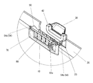
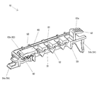
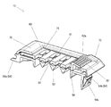
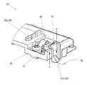
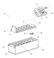
- FIG. 2 is a perspective view showing the first embodiment of the present invention, with a part of the opening / closing mechanism cut away. It is a perspective view of the storage body equipped with the opening / closing mechanism. It is the perspective view which looked at the storage body shown in FIG. 2 from the back side. It is a partial perspective view for demonstrating attachment of an opening-and-closing mechanism. It is a disassembled perspective view of an opening / closing mechanism. It is a perspective view of a case. It is the perspective view which looked at the shutter from the back side. It is a partial sectional view of a shutter for explaining a projection. It is the perspective view which looked at the cover from the back side.
- FIG. 2 is a perspective view corresponding to FIG.
- FIG. 2 is a perspective view of a fully opened state of the shutter corresponding to FIG. 1.
- FIG. 5 is a perspective view for explaining the opening / closing movement of the shutter, with a part of the opening / closing mechanism cut away.
- FIG. 13 is a perspective view corresponding to FIG. 12 in a fully opened state of the shutter. It is a partial perspective view for demonstrating the parting line of a case.
- the 2nd Embodiment of this invention is shown, The figure is the schematic exploded perspective view of an opening-closing mechanism, and the partial perspective view which looked at the shutter from the back surface side.
- the 3rd Embodiment of this invention is shown and the figure is a perspective view of an opening-closing mechanism.
- this figure is a perspective view of the opening / closing mechanism as seen from the back side.
- this figure is a cross-sectional view for explaining the attachment state of the opening / closing mechanism.
- FIGS. Opening / closing mechanism 10
- reference numeral 10 denotes an opening / closing mechanism.
- a duct 30 in which a housing 20 provided in a vehicle interior (not shown) is connected to an air conditioner (not shown).
- the shutter 60 is provided in the vent 23 which is the communication portion, and the temperature in the storage body 20 can be adjusted by changing the air volume by moving the shutter 60.
- the air conditioner is capable of blowing cold air or hot air through the duct 30.
- the storage body 20 is, for example, an upper box installed in front of the passenger seat, and is detachably attached to the vehicle interior that is an instrument panel (not shown).
- the storage body 20 that is an upper box is hollow, has an opening 21 on the front surface, and can store a storage item 22 such as a plastic bottle in the hollow interior.
- the opening 21 is provided with a lid that can be opened and closed. By closing the lid, the hollow interior can be sealed.
- a vent 23 is opened on the hollow inner side surface of the housing 20, and a duct 30 is connected to the vent 23 via a rectangular ring-shaped urethane 42.
- the instrument panel was illustrated as vehicle interior, it is not limited to this, A center console, a vehicle inner surface, the inner surface of a door, etc. may be sufficient.
- the upper box is illustrated as the storage body 20, it is not limited to this and may be a center box or the like.
- the vent 23 is opened on the hollow inner side surface of the storage body 20, the present invention is not limited to this, and it may be opened on the upper surface, bottom surface, rear surface, or the like of the hollow interior.
- the opening / closing mechanism 10 is detachably attached to the vent 23 from the hollow inner side of the storage body 20. As shown in FIG. 5, the opening / closing mechanism 10 is roughly composed of the following parts. The following (1) to (3) will be described later. (1) Case 50 (2) Shutter 60 (3) Cover 70 Although the opening / closing mechanism 10 includes the above-described (1) to (3), the present invention is not limited to this. For example, the cover 70 is merely a design shape and may be omitted.
- the case 50 is configured to hold a shutter 60 described later so that it can be opened and closed and to be detachably attached to the vent 23 of the storage body 20.
- the case 50 is integrally formed of a thermoplastic resin having appropriate elasticity and rigidity, for example, POM (polymer having an oxymethylene structure as a unit structure).
- POM polymer having an oxymethylene structure as a unit structure.
- the case 50 roughly includes the following parts. The following (1) to (7) will be described later. (1) Fixing hole 51 (2) Divider 52 (3) Holding part 53 (4) Mounting part 54 (5) Guide part 55 (6) Cover locking part 56 (7)
- Leaf spring 80 engagement part
- the shutter 60 is integrally formed of a thermoplastic resin having rigidity, for example, ABS resin (a general term for acrylonitrile, butadiene, and styrene copolymer resins). As shown in FIG. 5 and FIG. 7, the shutter 60 includes the following parts when roughly classified. The following (1) to (4) will be described later. (1) Movable hole 61 (2) Operation unit 62 (3) Protrusion 63 (engaged part) (4) Guided part 64
- the cover 70 is detachably attached to the case 50. Similar to the shutter 60, the cover 70 is integrally formed of a thermoplastic resin having rigidity, for example, ABS resin.
- the cover 70 is slightly larger than the case 50, is formed in a rectangular frame shape, and is attached so as to cover the outside of the case 50.
- the cover 70 is roughly divided into the following parts.
- Through hole 71 As shown in FIGS. 5 and 9, the through hole 71 is located at the center of the frame-shaped cover 70, penetrates inside and outside, is formed in a rectangular shape, and cool air or hot air blown through the case 50 and the shutter 60 is received. It can pass.
- Raised part 72 As shown in FIGS. 5, 12, and 13, the raised portion 72 is raised along both sides of an operation portion 62 described later of the shutter 60, and is inclined obliquely downward like the operation portion 62. .
- the locked portion 73 is locked to a cover locking portion 56 described later of the case 50.
- the locked portion 73 is roughly divided into the following portions.
- (3-1) Receiving part 73a As shown in FIGS. 5 and 9, the receiving portion 73 a is formed in a rectangular hole shape that penetrates the side edge portion of the cover 70 inward and outward, and a later-described claw portion 56 a of the case 50 is fitted therein.
- a pair of receiving portions 73a are formed along the longitudinal direction of the side edge portion of the cover 70, and a total of four receiving portions 73a are formed facing the side edge portions facing in the lateral direction.
- the receiving part 73a was formed in the hole shape, it is not limited to this, You may form in the convex shape which mutually fits with the nail
- (3-2) Slit 73b As shown in FIGS. 5 and 9, the slit 73 b is located in the interval between a pair of adjacent receiving portions 73 a and is formed in a slit shape extending halfway from the end surface of the side edge portion, and is a protrusion described later of the case 50. 56b gets stuck. A total of two slits 73b are formed facing the side edges facing the short direction.
- the fixing hole 51 communicates with the vent 23 of the storage body 20 and allows passage of cool air or hot air blown from the duct 30.
- the fixing holes 51 are formed in a square hole shape penetrating the front and back surfaces of the case 50, and are formed four apart along the longitudinal direction of the case 50.
- the fixing holes 51 are partitioned in the short direction of the case 50. In total, 8 pieces are formed.
- the total number of the fixing holes 51 is exemplified as eight, but the number is not limited to this, and a plurality of fixing holes 51 may be used, and two to seven, or nine or more may be formed.
- the diversion part 52 of case 50 As shown in FIGS. 1 and 6, three flow dividing portions 52 are positioned in the interval between two fixing holes 51 that are separated from each other in the longitudinal direction of the case 50, and are formed in three along the longitudinal direction of the case 50. In addition, the case 50 is divided into two in the short direction, so that a total of six cases are formed. As shown in FIG. 1, the diversion part 52 is formed in a triangular or heart shape having a sharp point on the duct 30 side, and cool air or hot air blown from the duct 30 is directed toward two adjacent fixing holes 51. It is for diversion. In addition, the total number of the flow dividing portions 52 is exemplified as 6.
- the number of the flow dividing portions 52 is not limited to this, and when the number of the fixing holes 51 is changed, the number of the flow dividing portions 52 also changes, and at least two adjacent fixed portions are fixed. It suffices if they are positioned within the interval between the holes 51.
- the holding unit 53 holds the shutter 60.
- the holding portions 53 are respectively located at a pair of side edge portions facing in the short direction of the case 50, and are bent and protruded in a cross-sectional L shape so as to face each other, with respect to one side edge portion in the longitudinal direction of the case 50. Two pieces are provided apart, and a total of four pieces are formed by a pair of side edges.
- the shutter 60 is slidably held within the facing distance between the upper surface and the holding portion 53 in FIG.
- the number of holding portions 53 is four as an example, the number is not limited to this, and one long side in the longitudinal direction of the case 50 may be provided for one side edge portion, or three or more may be formed. .
- the attaching portion 54 is for attaching to the storage body 20 as shown in FIGS. 1, 5 and 6.
- the attachment portion 54 is roughly composed of the following claws. (1) Rigid claw 54a As shown in FIGS. 1 and 5, the rigid claw 54 a is positioned at one end in the longitudinal direction of the case 50, bends and projects in a L-shaped cross section, and passes through the vent 23 of the storage body 20 to the outer surface side of the storage body 20. Acts as if caught on. As shown in FIG. 6, a pair of rigid claws 54a are formed apart in the short direction of the case 50. Although a pair of rigid claws 54a are formed, the present invention is not limited to this, and a single or three or more rigid claws 54a may be formed.
- the elastic claw 54b is located at the other end located on the opposite side of the one end having the rigid claw 54a, and projects the claw outward.
- the elastic claw 54b bends using the elasticity of the resin when passing through the vent 23 of the storage body 20, and is restored by the elastic restoring force of the resin after passing through the vent 23.
- a groove 54c is provided on the outer surface of the elastic claw 54b.
- the groove portion 54c is a thin hole for neatly taking out the surrounding nail shape, but after attaching the attachment portion 54 to the vent 23, when removing the attachment portion 54, a tool such as a minus screwdriver ( (Not shown) may be inserted and used to bend and remove the elastic claw 54b.
- a tool such as a minus screwdriver (Not shown) may be inserted and used to bend and remove the elastic claw 54b.
- the guide unit 55 guides the movement of the shutter 60 as shown in FIG.
- the guide part 55 includes the following parts when roughly classified. In addition, although the guide part 55 was divided into the following (1) and (2), it is not limited to this, It is good also as 1 piece, and good also as 3 or more pieces.
- (1) Guide convex part 55a As shown in FIG. 6, the guide protrusion 55a is positioned on the rigid claw 54a side and protrudes in a rib shape from the upper surface in the longitudinal direction of the case 50.
- the guide convex portion 55a is fitted into a guided concave portion 64a described later of the shutter 60, and when the shutter 60 is opened and closed, the guided concave portion 64a moves relative to the guide convex portion 55a.
- the reason why the outer surface of the guide convex portion 55a is curved is to allow the contact surface with the inner surface of the guided concave portion 64a to be easily adjusted by a design change. The effect that the area can be reduced can also be expected. Further, although the guide convex portion 55a is positioned on the rigid claw 54a side, it may be positioned on the elastic claw 54b side.
- the guide recess 55 b is located on the elastic claw 54 b side, has an end surface opened, and is formed in a rail shape extending in the longitudinal direction of the case 50.
- a guided convex portion 64b (to be described later) of the shutter 60 is fitted into the guide concave portion 55b, and when the shutter 60 is opened and closed, the guided convex portion 64b moves along the guide concave portion 55b.
- the cover locking part 56 is for detachably locking the cover 70.
- the cover engaging part 56 includes the following parts when roughly classified. (1) Claw part 56a As shown in FIG. 6, the claw portions 56 a protrude from a pair of outer surfaces facing the short direction of the case 50 and fit into the receiving portions 73 a that are holes of the cover 70.
- the claw portions 56 a are respectively positioned on the outer surfaces of the four holding portions 53 described above, and are formed in the same number as the four holding portions 53.
- the reason why the claw portion 56a is formed on the outer surface of the holding portion 53 is to arrange the parting line PL of the case 50 along the side edges of the holding portion 53 and the claw portion 56a as shown in FIG. is there. That is, in order to facilitate mold division, the fixed side of the mold is arranged along the arrow “a” in FIG. 14 and the movable side is arranged along the arrow “b” in FIG. is doing.
- the protrusion 56 b is positioned between a pair of adjacent claws 56 a, protrudes in a block shape from the outer surface of the case 50, and fits into the slit 73 b of the cover 70.
- the leaf spring 80 restricts movement at least in the process of opening and closing the shutter 60, and serves as an “engaging portion” that constitutes a part of “regulating means”. Function.
- the “regulating means” regulates movement at least in the process of opening and closing the shutter 60.
- the restricting means includes an “engagement portion” provided on one of the case 50 or the shutter 60, in the present embodiment, a leaf spring 80, an “engaged portion” provided on the other of the case 50 or the shutter 60, the book
- the shutter 60 is regulated by engagement with a protrusion 63 described later.
- the case 50 is provided with a leaf spring 80 and the shutter 60 is provided with a protrusion 63.
- the present invention is not limited to this, and the case 50 may be provided with a “projection” and the shutter 60 may be provided with a “plate spring”. Good.
- the leaf spring 80 (engagement portion) and the protrusion 63 (engaged portion) are illustrated, but the present invention is not limited to this, and the pin 102 (described later with reference to FIG. 15) (Engagement portion) and heart cam 110 (engaged portion) may be used, or a simple concavo-convex shape or friction resistance having no elasticity may be used.
- the position of the “regulating means” is not limited to the illustrated position, and may be provided between the case 50 and the shutter 60 and may be provided at any position.
- the leaf spring 80 is made of metal, is provided on a contact surface of the case 50 with the shutter 60, and is specifically fixed. As shown in FIG. 14, two round holes are formed at one end of the leaf spring 80, one of which fits into the set screw 81 and the other into the case 50 boss of the case, and is fixed to the case 50. .
- the other end of the leaf spring 80 is bent in a mountain shape and protrudes toward the shutter 60.
- the chevron portion of the leaf spring 80 engages with a plurality of protrusions 63 described later provided on the contact surface of the shutter 60 with the case 50.
- the movable hole 61 opens the ventilation hole 23 of the housing body 20, and communicates with the fixing hole 51 of the case 50, so that the ventilation hole 23 and the fixing hole are connected from the duct 30. Cold air or hot air blown through 51 can pass through.
- the movable hole 61 is formed in a rectangular hole shape that penetrates the front and back surfaces of the shutter 60, is formed to have approximately the same size as the fixing hole 51 of the case 50, and has the same number as the fixing hole 51. A total of eight are formed.
- the movable hole 61 is closed at a position moved immediately above the flow dividing portion 52 of the case 50 as shown in FIGS.
- the vent hole 23 can be closed by the shutter 60.
- the number of movable holes 61 a total of eight, which is the same number as the fixed holes 51, is illustrated, but the number is not limited to this, and the same number as the fixed holes 51 is sufficient, and when the number of the fixed holes 51 is changed Accordingly, the number of movable holes 61 may be changed to be the same.
- the operation unit 62 is for moving the shutter 60 by hand as shown in FIGS.
- the operation unit 62 extends in a L-shaped cross section from one end in the longitudinal direction of the shutter 60, from the right end in FIG. 5 to the right, and the upper surface of FIG. Further, an anti-slip uneven portion 62a is formed on the upper surface of the operation portion 62. Further, as shown in FIG. 12, the downward inclination of the upper surface of the operation unit 62 is set to have the same gradient as that of the raised portion 72 of the cover 70, and it is possible to know the state where the shutter 60 is closed by groping. On the other hand, when the shutter 60 is moved and the vent hole 23 is opened, the positions of the operation portion 62 and the raised portion 72 do not match as shown in FIG. You can know the state.
- the protrusion 63 is engaged with a leaf spring 80 that is an engaging portion, and is an “engaged portion” that constitutes a part of the “regulating means”. Function as.
- the protrusion 63 is formed on the surface corresponding to the cover 70, and a plurality of the protrusions 63 are formed. Specifically, as shown in FIG. 8, the protrusion 63 is composed of three first to third protrusions 63a to 63c that are located apart from each other in the longitudinal direction of the shutter 60. The right side of the first protrusion 63a located on the left side in FIG.
- the closing portion 63d is the closing portion 63d, and the state in which the leaf spring 80 is positioned in the closing portion 63d as shown in FIG. It is.
- the leaf spring 80 gets over the first protrusion 63a and, as shown in FIG. 10, a concave half-opened portion between the second protrusion 63b. Get stuck in 63e and stop.
- the state in which the leaf spring 80 is fitted in the half-open portion 63e is the half-open state of the vent hole 23.
- the leaf spring 80 gets over the second protrusion 63b, and as shown in FIG. 1, a concave fully open part between the third protrusion 63c. Get stuck in 63f and stop.
- the state in which the spring 80 is fitted in the fully open portion 63f is the fully open state of the vent 23 as shown in FIGS.
- the guided portion 64 guides the movement of the shutter 60 by engaging with the guide portion 55 of the case 50 as shown in FIG.
- the guided portion 64 is roughly divided into the following portions.
- the guided portion 64 is divided into the following (1) and (2).
- the number of guided portions 64 is not limited to this, and the number of guided portions 64 may be the same as the number of guide portions 55, and may be one as with the guide portions 55. Or three or more.
- the guided recessed portion 64 a is provided in the shutter 60, is formed on the facing surface facing the case 50, and is formed in a concave shape that fits into the guide convex portion 55 a of the case 50.
- the guided recessed portion 64a moves relative to the guide convex portion 55a in a state of being fitted to the guide convex portion 55a.
- the guided convex portion 64 b is provided on the shutter 60, is formed on the facing surface facing the case 50, and is formed in a convex shape that fits into the guide concave portion 55 b of the case 50.
- the guided convex portion 64b relatively moves along the guide concave portion 55b in a state of being caught in the guide concave portion 55b.
- the leaf spring 80 is fixed to the case 50 using a set screw 81, and then the shutter 60 is inserted below the holding portion 53.
- the shutter 60 is held movably in the case 50.
- the guided concave portion 64a on the shutter 60 side fits into the guide convex portion 55a on the case 50 side
- the guided convex portion 64b fits into the guide concave portion 55b on the case 50 side.
- the protrusion 63 on the shutter 60 side engages with the leaf spring 80 on the case 50 side.
- the shutter 60 can be detached from the case 50 so as to be removed from the holding portion 53 on the case 50 side.
- the cover 70 may be attached so as to cover the outside of the case 50. At this time, the claw 56a on the case 50 side fits into the hole-shaped receiving part 73a on the cover 70 side, and the projection 56b on the case 50 side fits into the slit 73b, and the cover 70 is fixed to the case 50. .
- the cover 70 can be removed from the case 50 by engaging and disengaging the claw portion 56a on the case 50 side that is fitted in the hole-shaped receiving portion 73a.
- the opening / closing mechanism 10 is detachably attached to the vent 23 from the hollow inner side of the storage body 20.
- the storage body 20 is fixed to the instrument panel, and a duct 30 is connected to the vent 23 thereof.
- the opening / closing mechanism 10 inserts the rigid claw 54a of the case 50 through the vent 23, and then brings the elastic claw 54b into contact with the outer edge portion of the vent 23 so that the entire opening / closing mechanism 10 is directed toward the vent 23. Just press.
- the elastic claw 54b bends using the elasticity of the resin when passing through the vent 23 of the container 20, and after passing through the vent 23, the elastic restoring force of the resin Restore by. For this reason, the restored elastic claw 54b is caught on the back side of the storage body 20, and the opening / closing mechanism 10 holds the outer wall of the storage body 20 from inside and outside in cooperation with the rigid claw 54a previously inserted, whereby the opening / closing mechanism 10 Fixed to.
- the container 20 itself is removed from the instrument panel (not shown), the elastic claw 54b is bent and pulled out from the vent 23, and then the rigid claw 54a is pulled out, The opening / closing mechanism 10 is removed from the vent 23.
- the operation unit 62 may be further slid leftward in FIG.
- the leaf spring 80 gets over the second protrusion 63b, and as shown in FIG. 1, the leaf spring 80 gets into the concave fully open portion 63f between the third protrusion 63c and stops.
- the operator can reliably stop the shutter 60 in the fully opened state by performing a groping operation without observing the movement of the shutter 60.
- the movable hole 61 of the shutter 60 communicates with the fixed hole 51 on the case 50 side, as shown in FIGS. For this reason, the cool air or the warm air blown from the duct 30 is blown into the hollow interior of the storage body 20 through the vent 23, the fixed hole 51, and the movable hole 61.
- the operation unit 62 When closing the shutter 60, the operation unit 62 may be slid to the right in FIG. 1, and the shutter 60 can be closed in the reverse order of the above description.
- a “restricting means” that restricts movement in the process of opening and closing the shutter 130 is configured from the pin 102 (engaging portion) and the heart cam 110 (engaged portion).
- the pin 102 is provided on the contact surface of the case 120 with the shutter 130 and constitutes an “engagement portion” of the restricting means.
- one end of the pin 102 is rotatably supported by the case 120, a pin portion is formed at the other end, and the pin portion protrudes toward the shutter 130.
- the heart cam 110 is provided on the shutter 130 and is formed on a surface opposite to the contact surface with the case 120 (the lower surface of the shutter 130 in FIG. 15) and engages with the pin 102, "Push-push type engagement".
- the pin 102 is located at one end of the swing cam 100 and protrudes in a cylindrical shape toward the shutter 130.
- the other end of the swing cam 100 is provided with a rotating shaft 101 that faces away from the pin 102, that is, protrudes toward the case 120.
- the rotation shaft 101 is supported by the case 120 so as to be rotatable.
- the heart cam 110 is formed in a groove shape so as to surround the heart-shaped protrusion, and the position where the pin 102 fits in the heart-shaped depression is set as the closed position of the shutter 130.
- the case 120 is provided with a fixing hole 121 and a guide groove 122 (holding portion).
- the shutter 130 is provided with a movable hole 131 and a guide protrusion 132.
- the guide protrusion 132 fits into the guide groove 122 on the case 120 side and is held so as to be slidable along the guide groove 122.
- a spring 140 is provided between the case 120 and the shutter 130, and the shutter 130 is urged with respect to the case 120 in one of the open / close directions, for example, the open direction.
- One end of the spring 140 is held by a concave spring receiver 133 provided on the shutter 130, and the other end is not shown, but abuts against the case 120 and is compressed between the case 120 and the shutter 130.
- the urging means for urging the shutter 130 in the opening direction is configured.
- the “push / push-type engagement” refers to a movement in which the pin 102 makes one turn while tracing around the heart cam 110, and specifically refers to the following series of operations.
- the pin 102 is positioned in the heart-shaped depression of the heart cam 110, and locks the shutter 130 in the closed position.
- the shutter 130 is urged in the opening direction by the urging force of the urging means, that is, the compression restoring force of the spring 140.
- the pin 102 is disengaged from the heart-shaped depression of the heart cam 110, and the locked state is released.
- the shutter 130 moves in the opening direction by the compression restoring force of the spring 140, and at this time, the pin 102 moves along the one side surface while tracing one side surface of the heart cam 110.
- the opened shutter 130 is moved in the closing direction, that is, “pushed” (pressed)
- the pin 102 moves along the one side while tracing the one side opposite to the heart cam 110.
- the shutter 130 is pushed back in the opening direction by the compression restoring force of the spring 140 when the force is released by “pushing” (pressing) the lock position until it goes too far.
- the pin 102 is again fitted into the heart-shaped depression of the heart cam 110 and locked, and the shutter 130 is locked in the locked position against the compression restoring force of the spring 140.
- the shutter 130 When opening the shutter 130 in the closed state, the shutter 130 may be moved in the closing direction against the compression restoring force of the spring 140. Thereby, the locked state of the restricting means is released, and it moves in the opening direction by the compression restoring force of the spring 140. At this time, the shutter 130 may be automatically moved to the fully open position by the compression restoring force of the spring 140, or may be automatically moved to the half open position and manually moved from the half open position to the fully open position. Good. On the other hand, when closing the shutter 130 in the closed state, the shutter 130 may be moved in the closing direction against the compression restoring force of the spring 140.
- the attachment portion 210 is provided with a rigid claw 220 at one end in the longitudinal direction of the case 200 and an elastic claw 230 at the other end.
- the elastic claws 230 extend downward in the figure, are provided in a folded shape with a V-shaped cross section upward from the lower end portion, and are formed in a pair in the short direction of the case 200.
- the elastic claw 230 is rich in elasticity compared to the “elastic claw 54b” of the first embodiment described above with reference to FIGS. 1 to 14, and makes it easy to remove the case 200.
- claw 230 was provided, it is not limited to this, You may provide two or more. Further, as shown in FIG. 17, a groove portion 221 is provided on the outer surface of the rigid claw 220. Note that the structures of the storage body 20, the case 200, the shutter 60, and the cover 70 are the same as those in the first embodiment described with reference to FIGS.
- the opening / closing mechanism 10 is detachably attached to the vent 23 from the hollow inner side of the storage body 20.
- the opening / closing mechanism 10 may be provided by placing the attachment portion 210 of the case 200, that is, the rigid claw 220 and the elastic claw 230 in the vent 23 and pushing them in as they are. When the mounting portion 210 is pushed in, the elastic claw 230 is bent using the elasticity of the resin when passing through the vent 23 of the storage body 20.
- the rigid claw 220 can also pass through the vent 23, and the rigid claw 220 and the elastic claw 230 pass through the vent 23.
- the elastic claw 230 is restored by the elastic restoring force of the resin after passing through the vent 23. Therefore, as shown in FIG. 18, the restored elastic claw 230 and the elastic claw 230 are hooked on the back side of the storage body 20, so that the outer wall of the storage body 20 is sandwiched from inside and outside, thereby opening and closing mechanism 10. Is fixed to the vent 23.
- the rigid claw 220 and the elastic claw 230 are positioned at the vent 23 and can be attached simply by being pushed in as they are.
- the storage body 20 itself can be removed from the instrument panel (not shown), and the opening / closing mechanism 10 can be removed by bending the elastic claw 230 from the outside of the storage body 20. .
- the mounting portion 54 of the case 50 is constituted by the following claws as shown in FIGS. (1) Rigid claw 54a (2) Elastic claw 54b
- the mounting portion 210 of the case 200 is constituted by the following claws. (3) rigid claw 220 (4) Elastic nail 230
- the case mounting portion is composed of the following claws.
- claw Although a 1st rigid claw is not shown in figure, it is located in the one end part of the longitudinal direction of a case, and has high rigidity.
- Second Rigid Claw The second rigid claw is not shown in the figure, but is located at one end in the longitudinal direction of the case, and has high rigidity like the first rigid claw.
- the second rigid claw may have the same structure as the first rigid claw or may have a different structure.
- the structure of the rigid claw 54a of the first embodiment may be adopted as the first rigid claw, and the same rigid claw 54a structure may be adopted as the second rigid claw. You may employ
- the structure of the rigid claw 220 of the third embodiment may be adopted as the first rigid claw, and the same structure of the rigid claw 220 may be adopted as the second rigid claw.
- the mounting portion is constituted by the first and second rigid claws, it is assumed that the rigid claws can be bent slightly or the vent side (not shown) to which these are attached is bent slightly.
- the opening and closing mechanism can be attached to the vent hole, although not shown, by strongly inserting the first and second rigid claws in accordance with the vent hole.
- the opening / closing mechanism although not shown, the storage body is removed from the instrument panel, and either the first or second rigid claw is forcibly bent from the outside of the storage body to open and close from the vent The mechanism can be removed.
- a groove through which at least one of the first and second rigid claws can pass through a part of the vent is not shown.
- a structure in which a rigid nail after passing through the vent is caught on the back side of the vent by inserting a rigid nail according to these and inserting a rigid nail in accordance with these and moving the rigid nail relative to the vent May be adopted.
- the case mounting portion is constituted by the following claws.
- First elastic claw Although not shown, the first elastic claw is located at one end in the longitudinal direction of the case, is rich in elasticity, and can be bent when passing through the vent. .
- Second elastic claw Although not shown, the second elastic claw is located at one end portion in the longitudinal direction of the case, is rich in elasticity like the second elastic claw, and passes through the vent. It can be bent.
- the second elastic claw may have the same structure as the first elastic claw or may have a different structure.
- the structure of the elastic claw 54b of the first embodiment may be adopted as the first elastic claw
- the structure of the same elastic claw 54b may be adopted as the second elastic claw.
- the structure of the elastic claw 230 of the third embodiment may be adopted as the first elastic claw, and the same structure of the elastic claw 230 may be adopted as the second elastic claw.
- the mounting portion is composed of the first and second elastic claws, although not shown in the drawing, by inserting according to the vent, at least one of them is bent so that it passes through the vent, and the opening / closing mechanism Can be attached to the vent.
- the opening / closing mechanism although not shown in the drawing, the opening / closing mechanism is removed from the vent by removing the storage body from the instrument panel and bending either the first or second elastic claw from the outside of the storage body. Can be removed.
Landscapes
- Engineering & Computer Science (AREA)
- Mechanical Engineering (AREA)
- Chemical & Material Sciences (AREA)
- Combustion & Propulsion (AREA)
- General Engineering & Computer Science (AREA)
- Physics & Mathematics (AREA)
- Thermal Sciences (AREA)
- Air-Conditioning For Vehicles (AREA)
- Vehicle Step Arrangements And Article Storage (AREA)
- Passenger Equipment (AREA)
Abstract
車両内装に設けられた収納体が空調装置と接続されているダクトと連通されており、その連通部分である通気口にシャッタを設け、シャッタを移動させることで風量を変化させて収納体内の温度を調整可能な通気口の開閉機構である。開閉機構は、ケースと、ケース上を移動するシャッタからなり、少なくともシャッタの開閉の過程で移動を規制する規制手段(例えば板ばね(係合部)、突部(被係合部))を有している。ケースは、シャッタを保持する保持部と、収納体に取付けるための取付部を備える。
Description
この発明は、通気口の開閉機構に関し、部品点数が少なく、二部材で組み立て性が良く、省スペースであるばかりでなく、収納体への脱着が容易で、作業性が良いものとすることができるようにしたものである。
従来、空調装置と接続されているダクトと、グローブボックスとを連通させるとともに、連通部分にシャッタを設けた「グローブボックスの保冷装置」が知られている(例えば特許文献1の実用新案登録請求の範囲及び第1図参照)。
また、従来、保冷ダクト又は保温ダクトの少なくとも一方を選択的に遮断するシャッタが設けられた「温冷機能付カップホルダー」が知られている(例えば特許文献1の段落番号「0006」、図1及び図3)。
また、従来、保冷ダクト又は保温ダクトの少なくとも一方を選択的に遮断するシャッタが設けられた「温冷機能付カップホルダー」が知られている(例えば特許文献1の段落番号「0006」、図1及び図3)。
しかし、上記した前者の従来の「グローブボックスの保冷装置」(特許文献1)では、グローブボックスにシャッタが直接設けられているので、メンテナンス時にシャッタの取り外しが困難で、作業性が悪いという第1の問題点があった。
また、上記した後者の従来の「温冷機能付カップホルダー」(特許文献2)は、シャッタの構造が複雑で、部品点数も多いので、組み立て工数が多く、又、全体が大型化してしまい、大きなスペースが必要となるという第2の問題点があった。
そこで、本発明は、上記した従来の技術の有する第1、第2の問題点に鑑みてなされたものであり、その目的は、部品点数が少なく、二部材で組み立て性が良く、省スペースであるばかりでなく、収納体への脱着が容易で、作業性が良い通気口の開閉機構を提供できるようにしたものである。
また、上記した後者の従来の「温冷機能付カップホルダー」(特許文献2)は、シャッタの構造が複雑で、部品点数も多いので、組み立て工数が多く、又、全体が大型化してしまい、大きなスペースが必要となるという第2の問題点があった。
そこで、本発明は、上記した従来の技術の有する第1、第2の問題点に鑑みてなされたものであり、その目的は、部品点数が少なく、二部材で組み立て性が良く、省スペースであるばかりでなく、収納体への脱着が容易で、作業性が良い通気口の開閉機構を提供できるようにしたものである。
本発明は、上記した目的を達成するため、次の点を特徴とする。
第1に、車両内装に設けられた収納体が空調装置と接続されているダクトと連通されており、その連通部分である通気口にシャッタを設け、シャッタを移動させることで風量を変化させて収納体内の温度を調整可能な通気口の開閉機構である。
第2に、開閉機構は、ケースと、ケース上を移動するシャッタからなり、少なくともシャッタの開閉の過程で移動を規制する規制手段(例えば板ばね、突部)を有している。なお、「規制手段」の一例として、板ばねと突部とを例示したが、これに限定されず、ピンとハートカムでもよいほか、弾性を有さない単なる凹凸形状や摩擦抵抗を利用したものでもよい。さらに、「規制手段」の位置も、ケースとシャッタとの間にあれば足り、どのような位置に設けてもよい。
第3に、ケースは、シャッタを保持する保持部と、収納体に取付けるための取付部を備える。
第1に、車両内装に設けられた収納体が空調装置と接続されているダクトと連通されており、その連通部分である通気口にシャッタを設け、シャッタを移動させることで風量を変化させて収納体内の温度を調整可能な通気口の開閉機構である。
第2に、開閉機構は、ケースと、ケース上を移動するシャッタからなり、少なくともシャッタの開閉の過程で移動を規制する規制手段(例えば板ばね、突部)を有している。なお、「規制手段」の一例として、板ばねと突部とを例示したが、これに限定されず、ピンとハートカムでもよいほか、弾性を有さない単なる凹凸形状や摩擦抵抗を利用したものでもよい。さらに、「規制手段」の位置も、ケースとシャッタとの間にあれば足り、どのような位置に設けてもよい。
第3に、ケースは、シャッタを保持する保持部と、収納体に取付けるための取付部を備える。
本発明では、取付部は、ケースの長手方向両端にそれぞれ設けられており、一方の取付部は剛体爪、他方の取付部は弾性爪であることが好ましい。この好ましい態様によれば、剛体爪と弾性爪とを使用して、収納体にワンタッチで取付可能なものとすることができる。
本発明では、規制手段は、ケース又はシャッタの一方に設けられた係合部(例えば板ばね)と、ケース又はシャッタの他方に設けられた被係合部(例えば突部)との係合によって規制されることが好ましい。この好ましい態様によれば、係合部と被係合部との係合によってシャッタの開閉を規制することで、シャッタの位置規制を精度良く行うことができる。
本発明は、次のように構成されることが好ましい。
第1に、係合部は、ケースのシャッタとの接触面に設けられた板ばねである。
第2に、被係合部は、シャッタのケースとの接触面に板ばねと係合する複数の突部である。
この好ましい態様によれば、板ばねと突部とから規制手段を構成することで、簡易構造で位置規制が確実に行うことができる。
第1に、係合部は、ケースのシャッタとの接触面に設けられた板ばねである。
第2に、被係合部は、シャッタのケースとの接触面に板ばねと係合する複数の突部である。
この好ましい態様によれば、板ばねと突部とから規制手段を構成することで、簡易構造で位置規制が確実に行うことができる。
本発明は、次のように構成されることが好ましい。
第1に、係合部は、ケースのシャッタとの接触面に設けられたピンである。
第2に、被係合部は、シャッタのケースとの接触面とは逆の面にピンと係合するハートカムでプッシュ・プッシュ式係合である。
第1に、係合部は、ケースのシャッタとの接触面に設けられたピンである。
第2に、被係合部は、シャッタのケースとの接触面とは逆の面にピンと係合するハートカムでプッシュ・プッシュ式係合である。
上記「プッシュ・プッシュ式係合」とは、ピンがハートカムの周囲をトレースしながら一回り巡る動きをいい、具体的には次の一連の動作をいう。
まず、シャッタの閉位置においては、ピンはハートカムのハート形の窪み内に位置し、シャッタを閉位置にロックしている。このとき、シャッタは、付勢手段(例えばスプリング)の付勢力により、開方向に付勢されている。
このロック位置から、シャッタを閉方向に更に「プッシュ」(押す)すると、ピンがハートカムのハート形の窪みから係脱し、ロック状態が解除される。
このため、シャッタは、前記付勢力により、開方向に移動し、その際にピンがハートカムの一側面をトレースしながら、当該一側面に沿って移動する。
一方、開いたシャッタを閉方向に移動、すなわち「プッシュ」(押す)すると、ピンがハートカムの反対側の一側面をトレースしながら、当該一側面に沿って移動する。その後、前記ロック位置を行き過ぎるまで「プッシュ」(押す)し、力を解放すると、シャッタが前記付勢力により、開方向に押し戻される。
このとき、ピンをハートカムのハート形の窪みに再度、はまり込んでロックされ、シャッタは前記付勢力に抗してロック位置にロックされる。
この好ましい態様によれば、ピンとハートカムから規制手段を構成することで、シャッタの開閉を手動で半自動で行なえ、操作性が良いものとすることができる。
まず、シャッタの閉位置においては、ピンはハートカムのハート形の窪み内に位置し、シャッタを閉位置にロックしている。このとき、シャッタは、付勢手段(例えばスプリング)の付勢力により、開方向に付勢されている。
このロック位置から、シャッタを閉方向に更に「プッシュ」(押す)すると、ピンがハートカムのハート形の窪みから係脱し、ロック状態が解除される。
このため、シャッタは、前記付勢力により、開方向に移動し、その際にピンがハートカムの一側面をトレースしながら、当該一側面に沿って移動する。
一方、開いたシャッタを閉方向に移動、すなわち「プッシュ」(押す)すると、ピンがハートカムの反対側の一側面をトレースしながら、当該一側面に沿って移動する。その後、前記ロック位置を行き過ぎるまで「プッシュ」(押す)し、力を解放すると、シャッタが前記付勢力により、開方向に押し戻される。
このとき、ピンをハートカムのハート形の窪みに再度、はまり込んでロックされ、シャッタは前記付勢力に抗してロック位置にロックされる。
この好ましい態様によれば、ピンとハートカムから規制手段を構成することで、シャッタの開閉を手動で半自動で行なえ、操作性が良いものとすることができる。
本発明では、ケースは、シャッタの移動をガイドするガイド部を設けていることが好ましい。この好ましい態様によれば、シャッタのガイド部を設定することで、スムーズな移動が可能なものとすることができる。
本発明では、ケースは、脱着可能なカバーを備えることが好ましい。この好ましい態様によれば、着脱可能なカバーを備えることで、メンテナンス性を損なうことなく、見栄えが良いものとすることができる。
本発明によれば、部品点数が少なく、二部材で組み立て性が良く、省スペースであるばかりでなく、収納体への脱着が容易で、作業性が良い通気口の開閉機構を提供できる。
(図1乃至14を用いた第1の実施の形態の説明)
つぎに、図1乃至14を用いて第1の実施の形態について説明する。
(開閉機構10)
図1中、10は開閉機構を示し、図2及び図4に示すように、車両内装(図示せず)に設けられた収納体20が空調装置(図示せず)と接続されているダクト30と連通されており、その連通部分である通気口23にシャッタ60を設け、シャッタ60を移動させることで風量を変化させて収納体20内の温度を調整可能なものである。
空調装置については、図示しないが、ダクト30を通して冷風或いは温風を送風可能なものである。
つぎに、図1乃至14を用いて第1の実施の形態について説明する。
(開閉機構10)
図1中、10は開閉機構を示し、図2及び図4に示すように、車両内装(図示せず)に設けられた収納体20が空調装置(図示せず)と接続されているダクト30と連通されており、その連通部分である通気口23にシャッタ60を設け、シャッタ60を移動させることで風量を変化させて収納体20内の温度を調整可能なものである。
空調装置については、図示しないが、ダクト30を通して冷風或いは温風を送風可能なものである。
収納体20は、例えば助手席の正面に設置されたアッパーボックスであり、図示しないが、インストルメントパネルである車両内装に着脱可能に取り付けられる。アッパーボックスである収納体20は、図2に示すように、中空で、前面に開口部21を有し、中空な内部にペットボトル等の収納物22を収納可能としている。また、開口部21には、図示しないが、リッドが開閉可能に設けられ、当該リッドを閉じることで、中空な内部を密閉できるようにしている。収納体20の中空な内部の側面には、図4に示すように、通気口23が開口され、当該通気口23に方形なリング状のウレタン42を介してダクト30が接続されている。
なお、車両内装として、インストルメントパネルを例示したが、これに限定されず、センターコンソール、車両内側面、ドアの内側面等でもよい。収納体20として、アッパーボックスを例示したが、これに限定されず、センターボックスなどでもよい。通気口23を、収納体20の中空な内部の側面に開口したが、これに限定されず、中空な内部の上面、底面或いは背面等に開口させてもよい。
なお、車両内装として、インストルメントパネルを例示したが、これに限定されず、センターコンソール、車両内側面、ドアの内側面等でもよい。収納体20として、アッパーボックスを例示したが、これに限定されず、センターボックスなどでもよい。通気口23を、収納体20の中空な内部の側面に開口したが、これに限定されず、中空な内部の上面、底面或いは背面等に開口させてもよい。
開閉機構10は、収納体20の中空な内部側から通気口23に着脱可能に取り付けられる。
開閉機構10は、図5に示すように、大別すると、次のパーツから構成されている。
なお、次の(1)~(3)について後述する。
(1)ケース50
(2)シャッタ60
(3)カバー70
なお、開閉機構10を、上記した(1)~(3)から構成したが、これに限定されず、例えばカバー70は意匠状のものに過ぎず、省いてもよい。
開閉機構10は、図5に示すように、大別すると、次のパーツから構成されている。
なお、次の(1)~(3)について後述する。
(1)ケース50
(2)シャッタ60
(3)カバー70
なお、開閉機構10を、上記した(1)~(3)から構成したが、これに限定されず、例えばカバー70は意匠状のものに過ぎず、省いてもよい。
(ケース50)
ケース50は、図1及び図4に示すように、後述するシャッタ60を開閉可能に保持し、収納体20の通気口23に着脱可能に取り付けられるものである。ケース50は、適度な弾性と剛性とを有する熱可塑性樹脂、例えばPOM(オキシメチレン(oxymethylene)構造を単位構造にもつ重合体)により一体的に成形されている。
ケース50は、図5、図6及び図14に示すように、大別すると、次の各部を備える。
なお、次の(1)~(7)について後述する。
(1)固定孔51
(2)分流部52
(3)保持部53
(4)取付部54
(5)ガイド部55
(6)カバー係止部56
(7)板ばね80(係合部)
ケース50は、図1及び図4に示すように、後述するシャッタ60を開閉可能に保持し、収納体20の通気口23に着脱可能に取り付けられるものである。ケース50は、適度な弾性と剛性とを有する熱可塑性樹脂、例えばPOM(オキシメチレン(oxymethylene)構造を単位構造にもつ重合体)により一体的に成形されている。
ケース50は、図5、図6及び図14に示すように、大別すると、次の各部を備える。
なお、次の(1)~(7)について後述する。
(1)固定孔51
(2)分流部52
(3)保持部53
(4)取付部54
(5)ガイド部55
(6)カバー係止部56
(7)板ばね80(係合部)
(シャッタ60)
シャッタ60は、図1、図4、図5及び図7に示すように、ケース50に保持され、ケース50上を移動することで、通気口23を開閉し、ダクト30から送風される風量を変化させるものである。シャッタ60は、剛性を有する熱可塑性樹脂、例えばABS樹脂(アクリロニトリル(Acrylonitrile)、ブタジエン(Butadiene)、スチレン(Styrene)共重合合成樹脂の総称)により一体的に成形されている。
シャッタ60は、図5及び図7に示すように、大別すると、次の各部を備える。
なお、次の(1)~(4)について後述する。
(1)可動孔61
(2)操作部62
(3)突部63(被係合部)
(4)被ガイド部64
シャッタ60は、図1、図4、図5及び図7に示すように、ケース50に保持され、ケース50上を移動することで、通気口23を開閉し、ダクト30から送風される風量を変化させるものである。シャッタ60は、剛性を有する熱可塑性樹脂、例えばABS樹脂(アクリロニトリル(Acrylonitrile)、ブタジエン(Butadiene)、スチレン(Styrene)共重合合成樹脂の総称)により一体的に成形されている。
シャッタ60は、図5及び図7に示すように、大別すると、次の各部を備える。
なお、次の(1)~(4)について後述する。
(1)可動孔61
(2)操作部62
(3)突部63(被係合部)
(4)被ガイド部64
(カバー70)
カバー70は、図5に示すように、ケース50に脱着可能に取り付けられるものである。カバー70は、シャッタ60と同様に、剛性を有する熱可塑性樹脂、例えばABS樹脂により一体的に成形されている。
カバー70は、ケース50より一回り大きく、方形の額縁状に形成され、ケース50の外側に被せるようにして取り付けられる。
カバー70は、図5に示すように、ケース50に脱着可能に取り付けられるものである。カバー70は、シャッタ60と同様に、剛性を有する熱可塑性樹脂、例えばABS樹脂により一体的に成形されている。
カバー70は、ケース50より一回り大きく、方形の額縁状に形成され、ケース50の外側に被せるようにして取り付けられる。
カバー70は、図5及び図9に示すように、大別すると、次の各部を備える。
(1)貫通口71
貫通口71は、図5及び図9に示すように、額縁状のカバー70の中央に位置し、内外に貫通し、方形に形成され、ケース50及びシャッタ60を通して送風された冷風或いは温風が通過可能なものである。
(2)隆起部72
隆起部72は、図5、図12及び図13に示すように、シャッタ60の後述する操作部62の両側に沿って隆起したものであり、操作部62と同様に斜め下向きに傾斜している。
(1)貫通口71
貫通口71は、図5及び図9に示すように、額縁状のカバー70の中央に位置し、内外に貫通し、方形に形成され、ケース50及びシャッタ60を通して送風された冷風或いは温風が通過可能なものである。
(2)隆起部72
隆起部72は、図5、図12及び図13に示すように、シャッタ60の後述する操作部62の両側に沿って隆起したものであり、操作部62と同様に斜め下向きに傾斜している。
(3)被係止部73
被係止部73は、図5及び図9に示すように、ケース50の後述するカバー係止部56に係止されるものである。
被係止部73は、大別すると、次の各部を備える。
(3-1)受部73a
受部73aは、図5及び図9に示すように、カバー70の側縁部を内外に貫通した方形の穴状に形成され、ケース50の後述する爪部56aがはまり込むものである。受部73aは、カバー70の側縁部の長手方向に沿って離れて一対形成され、短手方向に対向する側縁部に対向して位置し、計4個形成されている。
なお、受部73aを、穴状に形成したが、これに限定されず、ケース50の爪部56aと互いにはまり合う凸状に形成してもよい。
被係止部73は、図5及び図9に示すように、ケース50の後述するカバー係止部56に係止されるものである。
被係止部73は、大別すると、次の各部を備える。
(3-1)受部73a
受部73aは、図5及び図9に示すように、カバー70の側縁部を内外に貫通した方形の穴状に形成され、ケース50の後述する爪部56aがはまり込むものである。受部73aは、カバー70の側縁部の長手方向に沿って離れて一対形成され、短手方向に対向する側縁部に対向して位置し、計4個形成されている。
なお、受部73aを、穴状に形成したが、これに限定されず、ケース50の爪部56aと互いにはまり合う凸状に形成してもよい。
(3-2)スリット73b
スリット73bは、図5及び図9に示すように、隣接する一対の受部73aの間隔内に位置し、側縁部の端面から途中まで延びたスリット状に形成され、ケース50の後述する突起56bがはまり込むものである。スリット73bは、短手方向に対向する側縁部に対向して位置し、計2個形成されている。
スリット73bは、図5及び図9に示すように、隣接する一対の受部73aの間隔内に位置し、側縁部の端面から途中まで延びたスリット状に形成され、ケース50の後述する突起56bがはまり込むものである。スリット73bは、短手方向に対向する側縁部に対向して位置し、計2個形成されている。
(ケース50の固定孔51)
固定孔51は、図1及び図6に示すように、収納体20の通気口23と連通し、ダクト30から送風された冷風或いは温風が通過可能なものである。固定孔51は、ケース50の表裏面を貫通する方形の穴状に形成され、ケース50の長手方向に沿って離れて4個形成され、又、固定孔51はケース50の短手方向に仕切られて二分され、計8個形成されている。
なお、固定孔51の個数として、計8個を例示したが、これに限定されず、複数個であればよく、2~7個、或いは9個以上形成してもよい。
固定孔51は、図1及び図6に示すように、収納体20の通気口23と連通し、ダクト30から送風された冷風或いは温風が通過可能なものである。固定孔51は、ケース50の表裏面を貫通する方形の穴状に形成され、ケース50の長手方向に沿って離れて4個形成され、又、固定孔51はケース50の短手方向に仕切られて二分され、計8個形成されている。
なお、固定孔51の個数として、計8個を例示したが、これに限定されず、複数個であればよく、2~7個、或いは9個以上形成してもよい。
(ケース50の分流部52)
分流部52は、図1及び図6に示すように、ケース50の長手方向に離れて隣接した2個の固定孔51の間隔内にそれぞれ位置し、ケース50の長手方向に沿って3個形成され、又、ケース50の短手方向に二分され、計6個形成されている。
分流部52は、図1に示すように、ダクト30側に尖った断面三角形或いはハート形に形成され、ダクト30から送風された冷風或いは温風を、隣接した2個の固定孔51に向かって分流するためのものである。
なお、分流部52の個数として、計6個を例示したが、これに限定されず、固定孔51の個数を変更した場合には分流部52の個数も変化し、少なくとも隣接した2個の固定孔51の間隔内にそれぞれ位置させておけばよい。
分流部52は、図1及び図6に示すように、ケース50の長手方向に離れて隣接した2個の固定孔51の間隔内にそれぞれ位置し、ケース50の長手方向に沿って3個形成され、又、ケース50の短手方向に二分され、計6個形成されている。
分流部52は、図1に示すように、ダクト30側に尖った断面三角形或いはハート形に形成され、ダクト30から送風された冷風或いは温風を、隣接した2個の固定孔51に向かって分流するためのものである。
なお、分流部52の個数として、計6個を例示したが、これに限定されず、固定孔51の個数を変更した場合には分流部52の個数も変化し、少なくとも隣接した2個の固定孔51の間隔内にそれぞれ位置させておけばよい。
(ケース50の保持部53)
保持部53は、図1及び図6に示すように、シャッタ60を保持するものである。
保持部53は、ケース50の短手方向に対向する一対の側縁部にそれぞれ位置し、対向して断面L状に屈曲して突出し、一つの側縁部に対し、ケース50の長手方向に離れて2個設けられ、一対の側縁部で計4個形成されている。シャッタ60は、ケース50の図6において上面と保持部53との対向間隔内にスライド可能に保持される。
なお、保持部53の個数として、4個を例示したが、これに限定されず、一つの側縁部に対し、ケース50の長手方向に長く1個設け、或いは3個以上形成してもよい。
保持部53は、図1及び図6に示すように、シャッタ60を保持するものである。
保持部53は、ケース50の短手方向に対向する一対の側縁部にそれぞれ位置し、対向して断面L状に屈曲して突出し、一つの側縁部に対し、ケース50の長手方向に離れて2個設けられ、一対の側縁部で計4個形成されている。シャッタ60は、ケース50の図6において上面と保持部53との対向間隔内にスライド可能に保持される。
なお、保持部53の個数として、4個を例示したが、これに限定されず、一つの側縁部に対し、ケース50の長手方向に長く1個設け、或いは3個以上形成してもよい。
(ケース50の取付部54)
取付部54は、図1、図5及び図6に示すように、収納体20に取付けるためのものである。
取付部54は、大別すると、次の爪から構成されている。
(1)剛体爪54a
剛体爪54aは、図1及び図5に示すように、ケース50の長手方向の一端部に位置し、断面L状に屈曲して突出し、収納体20の通気口23を通して収納体20の外面側に引っ掛かるように作用する。剛体爪54aは、図6に示すように、ケース50の短手方向に離れて一対形成される。
なお、剛体爪54aを、一対形成したが、これに限定されず、単数或いは3個以上形成してもよい。
取付部54は、図1、図5及び図6に示すように、収納体20に取付けるためのものである。
取付部54は、大別すると、次の爪から構成されている。
(1)剛体爪54a
剛体爪54aは、図1及び図5に示すように、ケース50の長手方向の一端部に位置し、断面L状に屈曲して突出し、収納体20の通気口23を通して収納体20の外面側に引っ掛かるように作用する。剛体爪54aは、図6に示すように、ケース50の短手方向に離れて一対形成される。
なお、剛体爪54aを、一対形成したが、これに限定されず、単数或いは3個以上形成してもよい。
(2)弾性爪54b
弾性爪54bは、図1、図5及び図6に示すように、剛体爪54aを有する一端部と反対側に位置する他端部に位置し、爪を外向きに突出させている。弾性爪54bは、収納体20の通気口23を通過する際に、樹脂の弾性を利用して撓み、通気口23を通過後、樹脂の弾性復元力により復元する。
また、弾性爪54bの外側面には、図12に示すように、溝部54cを設けている。溝部54cは、周辺の爪形状をきれいに出すための肉抜きであるが、取付部54を通気口23に取り付けた後、取付部54の取外時に、当該溝部54cに例えばマイナスドライバー等の工具(図示せず)を差し込み、弾性爪54bを撓めて取り外すのに利用してもよい。
弾性爪54bは、図1、図5及び図6に示すように、剛体爪54aを有する一端部と反対側に位置する他端部に位置し、爪を外向きに突出させている。弾性爪54bは、収納体20の通気口23を通過する際に、樹脂の弾性を利用して撓み、通気口23を通過後、樹脂の弾性復元力により復元する。
また、弾性爪54bの外側面には、図12に示すように、溝部54cを設けている。溝部54cは、周辺の爪形状をきれいに出すための肉抜きであるが、取付部54を通気口23に取り付けた後、取付部54の取外時に、当該溝部54cに例えばマイナスドライバー等の工具(図示せず)を差し込み、弾性爪54bを撓めて取り外すのに利用してもよい。
(ケース50のガイド部55)
ガイド部55は、図6に示すように、シャッタ60の移動をガイドするものである。
ガイド部55は、大別すると、次の各部を備える。
なお、ガイド部55を次の(1)と(2)とに二分したが、これに限定されず、1個としてもよいし、或いは3個以上としてもよい。
(1)ガイド凸部55a
ガイド凸部55aは、図6に示すように、剛体爪54a側に位置し、上面からケース50の長手方向に長くリブ状に突出する。ガイド凸部55aには、シャッタ60の後述する被ガイド凹部64aにはまり込み、シャッタ60を開閉した際に、当該被ガイド凹部64aがガイド凸部55aに対して相対的に移動する。
なお、ガイド凸部55aの外側面を湾曲させたのは、被ガイド凹部64aの内側面との接触面を設計変更により容易に調整できる用にするためであるが、シャッタ60の移動時の接触面積を減少できるという効果も期待できる。また、ガイド凸部55aを、剛体爪54a側に位置させたが、弾性爪54b側に位置させてもよい。
ガイド部55は、図6に示すように、シャッタ60の移動をガイドするものである。
ガイド部55は、大別すると、次の各部を備える。
なお、ガイド部55を次の(1)と(2)とに二分したが、これに限定されず、1個としてもよいし、或いは3個以上としてもよい。
(1)ガイド凸部55a
ガイド凸部55aは、図6に示すように、剛体爪54a側に位置し、上面からケース50の長手方向に長くリブ状に突出する。ガイド凸部55aには、シャッタ60の後述する被ガイド凹部64aにはまり込み、シャッタ60を開閉した際に、当該被ガイド凹部64aがガイド凸部55aに対して相対的に移動する。
なお、ガイド凸部55aの外側面を湾曲させたのは、被ガイド凹部64aの内側面との接触面を設計変更により容易に調整できる用にするためであるが、シャッタ60の移動時の接触面積を減少できるという効果も期待できる。また、ガイド凸部55aを、剛体爪54a側に位置させたが、弾性爪54b側に位置させてもよい。
(2)ガイド凹部55b
ガイド凹部55bは、図6に示すように、弾性爪54b側に位置し、端面が開放するとともに、ケース50の長手方向に長く延びたレール状に形成されている。ガイド凹部55bには、シャッタ60の後述する被ガイド凸部64bがはまり込み、シャッタ60を開閉した際に、当該被ガイド凸部64bがガイド凹部55bに沿って移動する。
ガイド凹部55bは、図6に示すように、弾性爪54b側に位置し、端面が開放するとともに、ケース50の長手方向に長く延びたレール状に形成されている。ガイド凹部55bには、シャッタ60の後述する被ガイド凸部64bがはまり込み、シャッタ60を開閉した際に、当該被ガイド凸部64bがガイド凹部55bに沿って移動する。
(ケース50のカバー係止部56)
カバー係止部56は、図5及び図6に示すように、カバー70を着脱可能に係止するためのものである。
カバー係止部56は、大別すると、次の各部を備える。
(1)爪部56a
爪部56aは、図6に示すように、ケース50の短手方向に対向する一対の外側面からそれぞれ突出し、カバー70の穴である受部73aにはまり込むものである。爪部56aは、先に説明した計4個の保持部53の外側面にそれぞれ位置し、保持部53と同数の4個形成されている。
爪部56aを、保持部53の外側面に形成したのは、図14に示すように、ケース50のパーティングラインPLを、保持部53及び爪部56aの側縁に沿って配置するためである。すなわち、金型の固定側を、図14中、符号「a」の矢印に、可動側を符号「b」の矢印に沿ってそれぞれ配置することで、型割りを容易にするためである。
している。
カバー係止部56は、図5及び図6に示すように、カバー70を着脱可能に係止するためのものである。
カバー係止部56は、大別すると、次の各部を備える。
(1)爪部56a
爪部56aは、図6に示すように、ケース50の短手方向に対向する一対の外側面からそれぞれ突出し、カバー70の穴である受部73aにはまり込むものである。爪部56aは、先に説明した計4個の保持部53の外側面にそれぞれ位置し、保持部53と同数の4個形成されている。
爪部56aを、保持部53の外側面に形成したのは、図14に示すように、ケース50のパーティングラインPLを、保持部53及び爪部56aの側縁に沿って配置するためである。すなわち、金型の固定側を、図14中、符号「a」の矢印に、可動側を符号「b」の矢印に沿ってそれぞれ配置することで、型割りを容易にするためである。
している。
(2)突起56b
突起56bは、図6に示すように、隣接した一対の爪部56aの間に位置し、ケース50の外側面からブロック状に突出し、カバー70のスリット73bにはまり込むものである。
突起56bは、図6に示すように、隣接した一対の爪部56aの間に位置し、ケース50の外側面からブロック状に突出し、カバー70のスリット73bにはまり込むものである。
(板ばね80(係合部))
板ばね80は、図1、図6及び図14に示すように、少なくともシャッタ60の開閉の過程で移動を規制するものであり、「規制手段」の一部を構成する「係合部」として機能する。
上記「規制手段」は、少なくともシャッタ60の開閉の過程で移動を規制するものである。規制手段は、ケース50又はシャッタ60の一方に設けられた「係合部」、本実施の形態では板ばね80と、ケース50又はシャッタ60の他方に設けられた「被係合部」、本実施の形態ではシャッタ60の後述する突部63との係合によって規制される。なお、ケース50に、板ばね80を設け、シャッタ60に突部63を設けたが、これに限定されず、ケース50に「突部」を設け、シャッタ60に「板ばね」を設けてもよい。また、「規制手段」の一例として、板ばね80(係合部)と突部63(被係合部)とを例示したが、これに限定されず、図15を用いて後述するピン102(係合部)とハートカム110(被係合部)でもよいほか、弾性を有さない単なる凹凸形状や摩擦抵抗を利用したものでもよい。さらに、「規制手段」の位置も、図示した位置に限定されず、ケース50とシャッタ60との間にあれば足り、どのような位置に設けてもよい。
板ばね80は、金属製で、ケース50のシャッタ60との接触面に設けられ、具体的には固定される。板ばね80の一端部には、図14に示すように、丸孔が二つ形成され、一方は止めネジ81、他方はケースのケース50ボスにそれぞれはまり込み、ケース50に対して固定される。板ばね80の他端部は、シャッタ60に向かって山形に折れ曲がって突出している。板ばね80の山形部分は、シャッタ60のケース50との接触面に設けられた、後述する複数の突部63と係合する。
板ばね80は、図1、図6及び図14に示すように、少なくともシャッタ60の開閉の過程で移動を規制するものであり、「規制手段」の一部を構成する「係合部」として機能する。
上記「規制手段」は、少なくともシャッタ60の開閉の過程で移動を規制するものである。規制手段は、ケース50又はシャッタ60の一方に設けられた「係合部」、本実施の形態では板ばね80と、ケース50又はシャッタ60の他方に設けられた「被係合部」、本実施の形態ではシャッタ60の後述する突部63との係合によって規制される。なお、ケース50に、板ばね80を設け、シャッタ60に突部63を設けたが、これに限定されず、ケース50に「突部」を設け、シャッタ60に「板ばね」を設けてもよい。また、「規制手段」の一例として、板ばね80(係合部)と突部63(被係合部)とを例示したが、これに限定されず、図15を用いて後述するピン102(係合部)とハートカム110(被係合部)でもよいほか、弾性を有さない単なる凹凸形状や摩擦抵抗を利用したものでもよい。さらに、「規制手段」の位置も、図示した位置に限定されず、ケース50とシャッタ60との間にあれば足り、どのような位置に設けてもよい。
板ばね80は、金属製で、ケース50のシャッタ60との接触面に設けられ、具体的には固定される。板ばね80の一端部には、図14に示すように、丸孔が二つ形成され、一方は止めネジ81、他方はケースのケース50ボスにそれぞれはまり込み、ケース50に対して固定される。板ばね80の他端部は、シャッタ60に向かって山形に折れ曲がって突出している。板ばね80の山形部分は、シャッタ60のケース50との接触面に設けられた、後述する複数の突部63と係合する。
(シャッタ60の可動孔61)
可動孔61は、図1及び図7に示すように、収納体20の通気口23を開放するものであり、ケース50の固定孔51と連通することで、ダクト30から通気口23及び固定孔51を通って送風された冷風或いは温風が通過可能なものである。可動孔61は、図7に示すように、シャッタ60の表裏面を貫通する方形の穴状に形成され、ケース50の固定孔51と略同じ大きさに形成され、当該固定孔51と同数の計8個形成されている。可動孔61は、ケース50の分流部52の直上に移動した位置では、図11及び図12に示すように、塞がれ、シャッタ60により通気口23を塞ぐことができる。
なお、可動孔61の個数として、固定孔51と同数の計8個を例示したが、これに限定されず、固定孔51と同数であれば足り、固定孔51の個数を変更した場合にはそれに応じて可動孔61の個数を同数となるように変更すればよい。
可動孔61は、図1及び図7に示すように、収納体20の通気口23を開放するものであり、ケース50の固定孔51と連通することで、ダクト30から通気口23及び固定孔51を通って送風された冷風或いは温風が通過可能なものである。可動孔61は、図7に示すように、シャッタ60の表裏面を貫通する方形の穴状に形成され、ケース50の固定孔51と略同じ大きさに形成され、当該固定孔51と同数の計8個形成されている。可動孔61は、ケース50の分流部52の直上に移動した位置では、図11及び図12に示すように、塞がれ、シャッタ60により通気口23を塞ぐことができる。
なお、可動孔61の個数として、固定孔51と同数の計8個を例示したが、これに限定されず、固定孔51と同数であれば足り、固定孔51の個数を変更した場合にはそれに応じて可動孔61の個数を同数となるように変更すればよい。
(シャッタ60の操作部62)
操作部62は、図1及び図5に示すように、シャッタ60を手で移動させるためのものである。操作部62は、シャッタ60の長手方向の一端部、図5において向かって右側の端部から右側に向かって断面L字形に折れ曲がって延び、同図の上面を下り傾斜させている。また、操作部62の上面には、滑り止め用の凹凸部62aを形成している。
また、操作部62の上面の下り傾斜は、図12に示すように、カバー70の隆起部72と勾配が等しく設定し、手探りでシャッタ60が閉じた状態を知ることができる。これに対し、シャッタ60を移動し、通気口23を開放した際には、図13に示すように、操作部62と隆起部72との位置が一致しなくなることから、手探りでシャッタ60が開放した状態を知ることができる。
操作部62は、図1及び図5に示すように、シャッタ60を手で移動させるためのものである。操作部62は、シャッタ60の長手方向の一端部、図5において向かって右側の端部から右側に向かって断面L字形に折れ曲がって延び、同図の上面を下り傾斜させている。また、操作部62の上面には、滑り止め用の凹凸部62aを形成している。
また、操作部62の上面の下り傾斜は、図12に示すように、カバー70の隆起部72と勾配が等しく設定し、手探りでシャッタ60が閉じた状態を知ることができる。これに対し、シャッタ60を移動し、通気口23を開放した際には、図13に示すように、操作部62と隆起部72との位置が一致しなくなることから、手探りでシャッタ60が開放した状態を知ることができる。
(シャッタ60の突部63(被係合部))
突部63は、図1、図7及び図8に示すように、係合部である板ばね80と係合するものであり、「規制手段」の一部を構成する「被係合部」として機能する。
突部63は、カバー70と対応する面に形成され、複数形成されている。具体的には、突部63は、図8に示すように、シャッタ60の長手方向に離れて位置する3個の第1~第3突部63a~63cから構成されている。
図8の向かって左側に位置する第1突部63aの右側が、閉止部63dとなり、図11に示すように、当該閉止部63dに板ばね80が位置した状態が、通気口23の閉塞位置である。閉塞位置から、図11において向かって左側にシャッタ60を移動させると、板ばね80が第1突部63aを乗り越え、図10に示すように、第2突部63bとの間の凹状の半開部63eにはまり込んで一旦、停止する。半開部63eに板ばね80がはまり込んだ状態が、通気口23の半開状態である。
シャッタ60を、図10において向かって左側にシャッタ60を移動させると、板ばね80が第2突部63bを乗り越え、図1に示すように、第3突部63cとの間の凹状の全開部63fにはまり込んで停止する。全開部63fにばね80がはまり込んだ状態が、図1及び図13に示すように、通気口23の全開状態である。
突部63は、図1、図7及び図8に示すように、係合部である板ばね80と係合するものであり、「規制手段」の一部を構成する「被係合部」として機能する。
突部63は、カバー70と対応する面に形成され、複数形成されている。具体的には、突部63は、図8に示すように、シャッタ60の長手方向に離れて位置する3個の第1~第3突部63a~63cから構成されている。
図8の向かって左側に位置する第1突部63aの右側が、閉止部63dとなり、図11に示すように、当該閉止部63dに板ばね80が位置した状態が、通気口23の閉塞位置である。閉塞位置から、図11において向かって左側にシャッタ60を移動させると、板ばね80が第1突部63aを乗り越え、図10に示すように、第2突部63bとの間の凹状の半開部63eにはまり込んで一旦、停止する。半開部63eに板ばね80がはまり込んだ状態が、通気口23の半開状態である。
シャッタ60を、図10において向かって左側にシャッタ60を移動させると、板ばね80が第2突部63bを乗り越え、図1に示すように、第3突部63cとの間の凹状の全開部63fにはまり込んで停止する。全開部63fにばね80がはまり込んだ状態が、図1及び図13に示すように、通気口23の全開状態である。
(シャッタ60の被ガイド部64)
被ガイド部64は、図7に示すように、ケース50のガイド部55と係合することで、シャッタ60の移動をガイドするものである。
被ガイド部64は、大別すると、次の各部を備える。
なお、被ガイド部64を、次の(1)と(2)とに二分したが、これに限定されず、ガイド部55と同数であれば足り、ガイド部55と同様に1個としてもよいし、或いは3個以上としてもよい。
被ガイド部64は、図7に示すように、ケース50のガイド部55と係合することで、シャッタ60の移動をガイドするものである。
被ガイド部64は、大別すると、次の各部を備える。
なお、被ガイド部64を、次の(1)と(2)とに二分したが、これに限定されず、ガイド部55と同数であれば足り、ガイド部55と同様に1個としてもよいし、或いは3個以上としてもよい。
(1)被ガイド凹部64a
被ガイド凹部64aは、図7に示すように、シャッタ60に設けられ、ケース50と対向する対向面に形成され、ケース50のガイド凸部55aにはまり合う凹状に形成されている。被ガイド凹部64aは、シャッタ60を開閉した際に、ガイド凸部55aにはまり合った状態で、当該ガイド凸部55aに対して相対的に移動する。
被ガイド凹部64aは、図7に示すように、シャッタ60に設けられ、ケース50と対向する対向面に形成され、ケース50のガイド凸部55aにはまり合う凹状に形成されている。被ガイド凹部64aは、シャッタ60を開閉した際に、ガイド凸部55aにはまり合った状態で、当該ガイド凸部55aに対して相対的に移動する。
(2)被ガイド凸部64b
被ガイド凸部64bは、図7に示すように、シャッタ60に設けられ、ケース50と対向する対向面に形成され、ケース50のガイド凹部55bにはまる込む凸状に形成されている。被ガイド凸部64bは、シャッタ60を開閉した際に、ガイド凹部55bにはまる込んだ状態で、当該ガイド凹部55bに沿って相対的に移動する。
被ガイド凸部64bは、図7に示すように、シャッタ60に設けられ、ケース50と対向する対向面に形成され、ケース50のガイド凹部55bにはまる込む凸状に形成されている。被ガイド凸部64bは、シャッタ60を開閉した際に、ガイド凹部55bにはまる込んだ状態で、当該ガイド凹部55bに沿って相対的に移動する。
(開閉機構10の組立方法)
つぎに、上記構成を備えたケース50、シャッタ60及びカバー70の組立方法について説明する。
ケース50とシャッタ60との組み立ては、ケース50に止めネジ81を使用して板ばね80を固定した後、その保持部53の下側にシャッタ60を差し込めばよい。シャッタ60を差し込むと、シャッタ60がケース50に移動可能に保持される。
このとき、シャッタ60側の被ガイド凹部64aが、ケース50側のガイド凸部55aにはまり合い、又、被ガイド凸部64bがケース50側のガイド凹部55bにはまり込む。また、シャッタ60側の突部63が、ケース50側の板ばね80と係合する。
なお、シャッタ60は、ケース50側の保持部53から抜き取るようにして、ケース50から取り外し可能である。
つぎに、上記構成を備えたケース50、シャッタ60及びカバー70の組立方法について説明する。
ケース50とシャッタ60との組み立ては、ケース50に止めネジ81を使用して板ばね80を固定した後、その保持部53の下側にシャッタ60を差し込めばよい。シャッタ60を差し込むと、シャッタ60がケース50に移動可能に保持される。
このとき、シャッタ60側の被ガイド凹部64aが、ケース50側のガイド凸部55aにはまり合い、又、被ガイド凸部64bがケース50側のガイド凹部55bにはまり込む。また、シャッタ60側の突部63が、ケース50側の板ばね80と係合する。
なお、シャッタ60は、ケース50側の保持部53から抜き取るようにして、ケース50から取り外し可能である。
カバー70は、ケース50の外側に被せるように装着すればよい。このとき、カバー70側の穴状の受部73aに、ケース50側の爪部56aがはまり込み、又、スリット73bにケース50側の突起56bがはまり込み、カバー70がケース50に固定される。
なお、カバー70は、その穴状の受部73aにはまり込んでいるケース50側の爪部56aを係脱させることで、ケース50から取り外し可能である。
なお、カバー70は、その穴状の受部73aにはまり込んでいるケース50側の爪部56aを係脱させることで、ケース50から取り外し可能である。
(開閉機構10の着脱方法)
つぎに、組み立てた状態の開閉機構10の着脱方法について説明する。
開閉機構10は、図4に示すように、収納体20の中空な内部側から通気口23に着脱可能に取り付けられる。
収納体20は、図示しないが、インストルメントパネルに固定され、その通気口23にダクト30が連結されている。
開閉機構10は、ケース50の剛体爪54aを、通気口23を通して挿入し、その後、弾性爪54bを通気口23の外縁部に当接させ、その状態で開閉機構10全体を通気口23に向かって押し付ければよい。
開閉機構10を通気口23に押し付けると、弾性爪54bは、収納体20の通気口23を通過する際に、樹脂の弾性を利用して撓み、通気口23を通過後、樹脂の弾性復元力により復元する。このため、復元した弾性爪54bが収納体20の背面側に引っ掛かり、先に挿入した剛体爪54aと協働して収納体20の外壁を内外からはさみ持つことで、開閉機構10が通気口23に固定される。
つぎに、組み立てた状態の開閉機構10の着脱方法について説明する。
開閉機構10は、図4に示すように、収納体20の中空な内部側から通気口23に着脱可能に取り付けられる。
収納体20は、図示しないが、インストルメントパネルに固定され、その通気口23にダクト30が連結されている。
開閉機構10は、ケース50の剛体爪54aを、通気口23を通して挿入し、その後、弾性爪54bを通気口23の外縁部に当接させ、その状態で開閉機構10全体を通気口23に向かって押し付ければよい。
開閉機構10を通気口23に押し付けると、弾性爪54bは、収納体20の通気口23を通過する際に、樹脂の弾性を利用して撓み、通気口23を通過後、樹脂の弾性復元力により復元する。このため、復元した弾性爪54bが収納体20の背面側に引っ掛かり、先に挿入した剛体爪54aと協働して収納体20の外壁を内外からはさみ持つことで、開閉機構10が通気口23に固定される。
一方、開閉機構10を取り外す際には、収納体20自体をインストルメントパネル(図示せず)から取り外し、弾性爪54bを撓めて通気口23から抜き、その後、剛体爪54aを抜き取ることで、開閉機構10を通気口23から取り外すものである。
(シャッタ60の開閉)
通気口23に取り付けた状態でのシャッタ60の開閉について説明する。
図11及び図12に示すように、閉じたシャッタ60を開くには、その操作部62を、図11において向かって左側にスライドすればよい。
シャッタ60は、閉状態では、その可動孔61が、図11及び図12に示すように、ケース50の分流部52の直上に位置し、当該分流部52により閉じられている。このとき、ケース50側の板ばね80の山形部分が、図11に示すように、シャッタ60の閉止部63dに位置する。
操作部62をスライドさせると、板ばね80が第1突部63aを乗り越え、図10に示すように、第2突部63bとの間の凹状の半開部63eにはまり込んで一旦、停止し、このとき操作者にクリック感を与える。
このため、操作者は、シャッタ60の動きを見ること無しに、手探りで操作することで、シャッタ60を半開状態に確実に停止させることができる。
半開状態においては、シャッタ60の可動孔61の一方の半部が、図10に示すように、ケース50の分流部52により塞がれ、可動孔61の他方の半部が、ケース50側の固定孔51に連通する。
このため、ダクト30から送風された冷風或いは温風は、通気口23、固定孔51、可動孔61を通って収納体20の中空な内部に吹き込む。
通気口23に取り付けた状態でのシャッタ60の開閉について説明する。
図11及び図12に示すように、閉じたシャッタ60を開くには、その操作部62を、図11において向かって左側にスライドすればよい。
シャッタ60は、閉状態では、その可動孔61が、図11及び図12に示すように、ケース50の分流部52の直上に位置し、当該分流部52により閉じられている。このとき、ケース50側の板ばね80の山形部分が、図11に示すように、シャッタ60の閉止部63dに位置する。
操作部62をスライドさせると、板ばね80が第1突部63aを乗り越え、図10に示すように、第2突部63bとの間の凹状の半開部63eにはまり込んで一旦、停止し、このとき操作者にクリック感を与える。
このため、操作者は、シャッタ60の動きを見ること無しに、手探りで操作することで、シャッタ60を半開状態に確実に停止させることができる。
半開状態においては、シャッタ60の可動孔61の一方の半部が、図10に示すように、ケース50の分流部52により塞がれ、可動孔61の他方の半部が、ケース50側の固定孔51に連通する。
このため、ダクト30から送風された冷風或いは温風は、通気口23、固定孔51、可動孔61を通って収納体20の中空な内部に吹き込む。
シャッタ60を更に開くには、その操作部62を、図10において向かって左側に、更にスライドすればよい。
操作部62をスライドさせると、板ばね80が第2突部63bを乗り越え、図1に示すように、第3突部63cとの間の凹状の全開部63fにはまり込んで停止し、このとき操作者にクリック感を与える。
このため、操作者は、シャッタ60の動きを見ること無しに、手探りで操作することで、シャッタ60を全開状態に確実に停止させることができる。
全開状態においては、シャッタ60の可動孔61が、図1及び図13に示すように、ケース50側の固定孔51に連通する。
このため、ダクト30から送風された冷風或いは温風は、通気口23、固定孔51、可動孔61を通って収納体20の中空な内部に吹き込む。
操作部62をスライドさせると、板ばね80が第2突部63bを乗り越え、図1に示すように、第3突部63cとの間の凹状の全開部63fにはまり込んで停止し、このとき操作者にクリック感を与える。
このため、操作者は、シャッタ60の動きを見ること無しに、手探りで操作することで、シャッタ60を全開状態に確実に停止させることができる。
全開状態においては、シャッタ60の可動孔61が、図1及び図13に示すように、ケース50側の固定孔51に連通する。
このため、ダクト30から送風された冷風或いは温風は、通気口23、固定孔51、可動孔61を通って収納体20の中空な内部に吹き込む。
シャッタ60を閉じる際には、その操作部62を、図1において向かって右側に、スライドさせればよく、上記した説明と逆の手順でシャッタ60を閉じることができる。
(図15を用いた第2の実施の形態の説明)
つぎに、図15を用いて第2の実施の形態について説明する。
本実施の形態の特徴は、ピン102(係合部)とハートカム110(被係合部)から、シャッタ130の開閉の過程で移動を規制する「規制手段」を構成した点である。
ピン102は、図15に示すように、ケース120のシャッタ130との接触面に設けられ、規制手段の「係合部」を構成する。具体的には、ピン102は、一端部がケース120に回転可能に支持され、他端部にピン部が形成され、ピン部はシャッタ130に向かって突出する。
ハートカム110は、図15に示すように、シャッタ130に設けられ、ケース120との接触面とは逆の面(同図においてシャッタ130の下面)に形成され、ピン102と係合する、すなわち「プッシュ・プッシュ式係合」するものである。
つぎに、図15を用いて第2の実施の形態について説明する。
本実施の形態の特徴は、ピン102(係合部)とハートカム110(被係合部)から、シャッタ130の開閉の過程で移動を規制する「規制手段」を構成した点である。
ピン102は、図15に示すように、ケース120のシャッタ130との接触面に設けられ、規制手段の「係合部」を構成する。具体的には、ピン102は、一端部がケース120に回転可能に支持され、他端部にピン部が形成され、ピン部はシャッタ130に向かって突出する。
ハートカム110は、図15に示すように、シャッタ130に設けられ、ケース120との接触面とは逆の面(同図においてシャッタ130の下面)に形成され、ピン102と係合する、すなわち「プッシュ・プッシュ式係合」するものである。
ピン102は、スイングカム100の一端部に位置し、シャッタ130に向かって円柱形に突出する。スイングカム100の他端部には、ピン102と背向し、すなわちケース120に向かって突出する回転軸101が設けられている。回転軸101は、図示しないが、ケース120に旋回可能に支持される。
ハートカム110は、ハート形の突起を取り囲むように、溝状に形成され、ハート形の窪み内にピン102がはまり込んだ位置を、シャッタ130の閉位置に設定している。
また、ケース120には、固定孔121、ガイド溝122(保持部)を設けている。
シャッタ130には、ハートカム110のほか、可動孔131、ガイド突起132を設けている。ガイド突起132は、ケース120側のガイド溝122にはまり込み、当該ガイド溝122に沿ってスライド可能に保持される。
ケース120のシャッタ130との間には、スプリング140を設け、ケース120に対してシャッタ130を開閉のいずれか一方向、例えば開方向に付勢する。スプリング140は、一端部がシャッタ130に設けられた凹状のスプリング受け133に保持され、他端部が図示しないが、ケース120に当接し、ケース120のシャッタ130との間で圧縮され、ケース120に対してシャッタ130を開方向に付勢する付勢手段を構成する。
ハートカム110は、ハート形の突起を取り囲むように、溝状に形成され、ハート形の窪み内にピン102がはまり込んだ位置を、シャッタ130の閉位置に設定している。
また、ケース120には、固定孔121、ガイド溝122(保持部)を設けている。
シャッタ130には、ハートカム110のほか、可動孔131、ガイド突起132を設けている。ガイド突起132は、ケース120側のガイド溝122にはまり込み、当該ガイド溝122に沿ってスライド可能に保持される。
ケース120のシャッタ130との間には、スプリング140を設け、ケース120に対してシャッタ130を開閉のいずれか一方向、例えば開方向に付勢する。スプリング140は、一端部がシャッタ130に設けられた凹状のスプリング受け133に保持され、他端部が図示しないが、ケース120に当接し、ケース120のシャッタ130との間で圧縮され、ケース120に対してシャッタ130を開方向に付勢する付勢手段を構成する。
(「プッシュ・プッシュ式係合」)
上記「プッシュ・プッシュ式係合」とは、ピン102がハートカム110の周囲をトレースしながら一回り巡る動きをいい、具体的には次の一連の動作をいう。
まず、シャッタ130の閉位置においては、ピン102はハートカム110のハート形の窪み内に位置し、シャッタ130を閉位置にロックしている。このとき、シャッタ130は、付勢手段の付勢力、すなわちスプリング140の圧縮復元力により、開方向に付勢されている。
このロック位置から、シャッタ130を閉方向に更に「プッシュ」(押す)すると、ピン102がハートカム110のハート形の窪みから係脱し、ロック状態が解除される。
このため、シャッタ130は、スプリング140の圧縮復元力により、開方向に移動し、その際にピン102がハートカム110の一側面をトレースしながら、当該一側面に沿って移動する。
一方、開いたシャッタ130を閉方向に移動、すなわち「プッシュ」(押す)すると、ピン102がハートカム110の反対側の一側面をトレースしながら、当該一側面に沿って移動する。その後、前記ロック位置を行き過ぎるまで「プッシュ」(押す)し、力を解放すると、シャッタ130がスプリング140の圧縮復元力により、開方向に押し戻される。
このとき、ピン102をハートカム110のハート形の窪みに再度、はまり込んでロックされ、シャッタ130はスプリング140の圧縮復元力に抗してロック位置にロックされる。
上記「プッシュ・プッシュ式係合」とは、ピン102がハートカム110の周囲をトレースしながら一回り巡る動きをいい、具体的には次の一連の動作をいう。
まず、シャッタ130の閉位置においては、ピン102はハートカム110のハート形の窪み内に位置し、シャッタ130を閉位置にロックしている。このとき、シャッタ130は、付勢手段の付勢力、すなわちスプリング140の圧縮復元力により、開方向に付勢されている。
このロック位置から、シャッタ130を閉方向に更に「プッシュ」(押す)すると、ピン102がハートカム110のハート形の窪みから係脱し、ロック状態が解除される。
このため、シャッタ130は、スプリング140の圧縮復元力により、開方向に移動し、その際にピン102がハートカム110の一側面をトレースしながら、当該一側面に沿って移動する。
一方、開いたシャッタ130を閉方向に移動、すなわち「プッシュ」(押す)すると、ピン102がハートカム110の反対側の一側面をトレースしながら、当該一側面に沿って移動する。その後、前記ロック位置を行き過ぎるまで「プッシュ」(押す)し、力を解放すると、シャッタ130がスプリング140の圧縮復元力により、開方向に押し戻される。
このとき、ピン102をハートカム110のハート形の窪みに再度、はまり込んでロックされ、シャッタ130はスプリング140の圧縮復元力に抗してロック位置にロックされる。
(シャッタ130の開閉)
閉状態のシャッタ130を開く際には、スプリング140の圧縮復元力に抗して、シャッタ130を閉方向に移動すればよい。これにより、規制手段のロック状態が解除され、スプリング140の圧縮復元力により、開方向に移動する。このとき、シャッタ130を、スプリング140の圧縮復元力により、全開位置まで自動的に移動させてもよいし、或いは半開位置まで自動的に移動させ、半開位置から全開位置まで手動で移動させてもよい。
一方、閉状態のシャッタ130を閉じる際には、スプリング140の圧縮復元力に抗して、シャッタ130を閉方向に移動すればよい。シャッタ130を、閉位置を行き過ぎるまで移動させて、力を開放すると、スプリング140の圧縮復元力に開方向に押し戻され、規制手段がロック状態となり、シャッタ130はスプリング140の圧縮復元力に抗してロック位置にロックされる。
閉状態のシャッタ130を開く際には、スプリング140の圧縮復元力に抗して、シャッタ130を閉方向に移動すればよい。これにより、規制手段のロック状態が解除され、スプリング140の圧縮復元力により、開方向に移動する。このとき、シャッタ130を、スプリング140の圧縮復元力により、全開位置まで自動的に移動させてもよいし、或いは半開位置まで自動的に移動させ、半開位置から全開位置まで手動で移動させてもよい。
一方、閉状態のシャッタ130を閉じる際には、スプリング140の圧縮復元力に抗して、シャッタ130を閉方向に移動すればよい。シャッタ130を、閉位置を行き過ぎるまで移動させて、力を開放すると、スプリング140の圧縮復元力に開方向に押し戻され、規制手段がロック状態となり、シャッタ130はスプリング140の圧縮復元力に抗してロック位置にロックされる。
(図16~18を用いた第3の実施の形態の説明)
つぎに、図16~18を用いて第3の実施の形態について説明する。
本実施の形態の特徴は、取付部210の変形例を提示した点である。
すなわち、取付部210は、ケース200の長手方向の一端部に剛体爪220を、他端部には弾性爪230をそれぞれ設けている。弾性爪230は、図18に示すように、同図において下向きに延び、下端部から上方に向かって断面V字形に折り返し状に設けられ、ケース200の短手方向に一対形成されている。弾性爪230は、先に図1~14を用いて説明した第1の実施の形態の「弾性爪54b」と比較し、弾性に富み、ケース200を取り外しし易くしている。なお、弾性爪230を、単数設けたが、これに限定されず、2個以上設けてもよい。
また、剛体爪220の外側面には、図17に示すように、溝部221を設けている。
なお、収納体20、ケース200、シャッタ60、カバー70の構造については、図1~14を用いて説明した第1の実施の形態と同様の構造を有し、説明を省略する。
つぎに、図16~18を用いて第3の実施の形態について説明する。
本実施の形態の特徴は、取付部210の変形例を提示した点である。
すなわち、取付部210は、ケース200の長手方向の一端部に剛体爪220を、他端部には弾性爪230をそれぞれ設けている。弾性爪230は、図18に示すように、同図において下向きに延び、下端部から上方に向かって断面V字形に折り返し状に設けられ、ケース200の短手方向に一対形成されている。弾性爪230は、先に図1~14を用いて説明した第1の実施の形態の「弾性爪54b」と比較し、弾性に富み、ケース200を取り外しし易くしている。なお、弾性爪230を、単数設けたが、これに限定されず、2個以上設けてもよい。
また、剛体爪220の外側面には、図17に示すように、溝部221を設けている。
なお、収納体20、ケース200、シャッタ60、カバー70の構造については、図1~14を用いて説明した第1の実施の形態と同様の構造を有し、説明を省略する。
(開閉機構10の着脱方法)
つぎに、開閉機構10の着脱方法について説明する。
開閉機構10は、図16に示すように、収納体20の中空な内部側から通気口23に着脱可能に取り付けられる。
開閉機構10は、ケース200の取付部210、すなわち剛体爪220及び弾性爪230を通気口23に位置させ、そのまま押し込めばよい。
取付部210を押し込むと、弾性爪230が収納体20の通気口23を通過する際に、樹脂の弾性を利用して撓み込む。このため、弾性爪230が撓み込むことで、剛体爪220も通気口23を通過可能となり、剛体爪220及び弾性爪230が通気口23を通過する。
弾性爪230は、通気口23を通過後、樹脂の弾性復元力により復元する。このため、復元した弾性爪230と、弾性爪230とが、図18に示すように、収納体20の背面側に引っ掛かることで、収納体20の外壁を内外からはさみ持つことで、開閉機構10が通気口23に固定される。
上記したように、剛体爪220及び弾性爪230を通気口23に位置させ、そのまま押し込めむだけで取り付けることができる利点がある。
つぎに、開閉機構10の着脱方法について説明する。
開閉機構10は、図16に示すように、収納体20の中空な内部側から通気口23に着脱可能に取り付けられる。
開閉機構10は、ケース200の取付部210、すなわち剛体爪220及び弾性爪230を通気口23に位置させ、そのまま押し込めばよい。
取付部210を押し込むと、弾性爪230が収納体20の通気口23を通過する際に、樹脂の弾性を利用して撓み込む。このため、弾性爪230が撓み込むことで、剛体爪220も通気口23を通過可能となり、剛体爪220及び弾性爪230が通気口23を通過する。
弾性爪230は、通気口23を通過後、樹脂の弾性復元力により復元する。このため、復元した弾性爪230と、弾性爪230とが、図18に示すように、収納体20の背面側に引っ掛かることで、収納体20の外壁を内外からはさみ持つことで、開閉機構10が通気口23に固定される。
上記したように、剛体爪220及び弾性爪230を通気口23に位置させ、そのまま押し込めむだけで取り付けることができる利点がある。
一方、開閉機構10を取り外す際には、収納体20自体を、インストルメントパネル(図示せず)から取り外し、収納体20の外側から弾性爪230を撓めて、開閉機構10を取り外すことができる。
(他の実施の形態)
つぎに、図示は省略するが、本発明の他の実施の形態について説明する。
本実施の形態の特徴は、収納体の取付部のバリエーションを提供する点である。
すなわち、図1~14を用いて説明した第1の実施の形態では、ケース50の取付部54を、図1、図5及び図6に示すように、次の爪から構成した。
(1)剛体爪54a
(2)弾性爪54b
また、図16以降を用いて説明した第3の実施の形態では、ケース200の取付部210を、次の爪から構成した。
(3)剛体爪220
(4)弾性爪230
これに対し、本実施の形態の第1変形例は、図示しないが、ケースの取付部を、次の爪から構成したものである。
(5)第1の剛体爪
第1の剛体爪は、図示しないが、ケースの長手方向の一端部に位置し、剛性が高いものである。
(6)第2の剛体爪
第2の剛体爪は、同じく図示しないが、ケースの長手方向の一端部に位置し、第1の剛体爪と同様に剛性が高いものである。第2の剛体爪は、第1の剛体爪と同じ構造でもよいし、或いは異なる構造としてもよい。
具体例としては、第1の剛体爪として、第1の実施の形態の剛体爪54aの構造を採用し、第2の剛体爪として、同じ剛体爪54aの構造を採用してもよいし、或いは第3の実施の形態の剛体爪220の構造を採用してもよい。また、第1の剛体爪として、第3の実施の形態の剛体爪220の構造を採用し、第2の剛体爪として、同じ剛体爪220の構造を採用してもよい。
第1、第2の剛体爪から取付部を構成した際には、剛体爪が少し撓むことができるか、或いはこれらを取り付ける通気口側(図示せず)が少し撓むというという前提であれば、第1、第2の剛体爪を通気口に合わせて強く挿入することで、図示しないが、開閉機構を通気口に取り付けることができる。開閉機構を取り外す際には、図示しないが、収納体をインストルメントパネルから取り外し、収納体の外側から第1、第2の剛体爪のいずれかを無理に撓めることで、通気口から開閉機構を取り外すことができる。なお、第1、第2の剛体爪及び通気口側の剛性が高い場合には、図示しないが、通気口の一部に第1、第2の剛体爪のいずれか少なくとも一方が通過可能な溝や凹部等を設けておき、これらに合わせて剛体爪を挿入し、挿入後、通気口に対して剛体爪を移動させることで、通気口を通過後の剛体爪が通気口の裏側に引っ掛かる構造を採用してもよい。
つぎに、図示は省略するが、本発明の他の実施の形態について説明する。
本実施の形態の特徴は、収納体の取付部のバリエーションを提供する点である。
すなわち、図1~14を用いて説明した第1の実施の形態では、ケース50の取付部54を、図1、図5及び図6に示すように、次の爪から構成した。
(1)剛体爪54a
(2)弾性爪54b
また、図16以降を用いて説明した第3の実施の形態では、ケース200の取付部210を、次の爪から構成した。
(3)剛体爪220
(4)弾性爪230
これに対し、本実施の形態の第1変形例は、図示しないが、ケースの取付部を、次の爪から構成したものである。
(5)第1の剛体爪
第1の剛体爪は、図示しないが、ケースの長手方向の一端部に位置し、剛性が高いものである。
(6)第2の剛体爪
第2の剛体爪は、同じく図示しないが、ケースの長手方向の一端部に位置し、第1の剛体爪と同様に剛性が高いものである。第2の剛体爪は、第1の剛体爪と同じ構造でもよいし、或いは異なる構造としてもよい。
具体例としては、第1の剛体爪として、第1の実施の形態の剛体爪54aの構造を採用し、第2の剛体爪として、同じ剛体爪54aの構造を採用してもよいし、或いは第3の実施の形態の剛体爪220の構造を採用してもよい。また、第1の剛体爪として、第3の実施の形態の剛体爪220の構造を採用し、第2の剛体爪として、同じ剛体爪220の構造を採用してもよい。
第1、第2の剛体爪から取付部を構成した際には、剛体爪が少し撓むことができるか、或いはこれらを取り付ける通気口側(図示せず)が少し撓むというという前提であれば、第1、第2の剛体爪を通気口に合わせて強く挿入することで、図示しないが、開閉機構を通気口に取り付けることができる。開閉機構を取り外す際には、図示しないが、収納体をインストルメントパネルから取り外し、収納体の外側から第1、第2の剛体爪のいずれかを無理に撓めることで、通気口から開閉機構を取り外すことができる。なお、第1、第2の剛体爪及び通気口側の剛性が高い場合には、図示しないが、通気口の一部に第1、第2の剛体爪のいずれか少なくとも一方が通過可能な溝や凹部等を設けておき、これらに合わせて剛体爪を挿入し、挿入後、通気口に対して剛体爪を移動させることで、通気口を通過後の剛体爪が通気口の裏側に引っ掛かる構造を採用してもよい。
本実施の形態の第2変形例は、図示しないが、ケースの取付部を、次の爪から構成したものである。
(7)第1の弾性爪
第1の弾性爪は、図示しないが、ケースの長手方向の一端部に位置し、弾性に富み、通気口を通過する際に撓むことが可能なものである。
(8)第2の弾性爪
第2の弾性爪は、同じく図示しないが、ケースの長手方向の一端部に位置し、第2の弾性爪と同様に弾性に富み、通気口を通過する際に撓むことが可能なものである。第2の弾性爪は、第1の弾性爪と同じ構造でもよいし、或いは異なる構造としてもよい。
具体例としては、第1の弾性爪として、第1の実施の形態の弾性爪54bの構造を採用し、第2の弾性爪として、同じ弾性爪54bの構造を採用してもよいし、或いは第3の実施の形態の弾性爪230の構造を採用してもよい。また、第1の弾性爪として、第3の実施の形態の弾性爪230の構造を採用し、第2の弾性爪として、同じ弾性爪230の構造を採用してもよい。
第1、第2の弾性爪から取付部を構成した際には、図示しないが、通気口に合わせて挿入することで、いずかれ少なくとも一方が撓むことで通気口を通過し、開閉機構を通気口に取り付けることができる。開閉機構を取り外す際には、図示しないが、収納体をインストルメントパネルから取り外し、収納体の外側から第1、第2の弾性爪のいずれかを撓めることで、通気口から開閉機構を取り外すことができる。
(7)第1の弾性爪
第1の弾性爪は、図示しないが、ケースの長手方向の一端部に位置し、弾性に富み、通気口を通過する際に撓むことが可能なものである。
(8)第2の弾性爪
第2の弾性爪は、同じく図示しないが、ケースの長手方向の一端部に位置し、第2の弾性爪と同様に弾性に富み、通気口を通過する際に撓むことが可能なものである。第2の弾性爪は、第1の弾性爪と同じ構造でもよいし、或いは異なる構造としてもよい。
具体例としては、第1の弾性爪として、第1の実施の形態の弾性爪54bの構造を採用し、第2の弾性爪として、同じ弾性爪54bの構造を採用してもよいし、或いは第3の実施の形態の弾性爪230の構造を採用してもよい。また、第1の弾性爪として、第3の実施の形態の弾性爪230の構造を採用し、第2の弾性爪として、同じ弾性爪230の構造を採用してもよい。
第1、第2の弾性爪から取付部を構成した際には、図示しないが、通気口に合わせて挿入することで、いずかれ少なくとも一方が撓むことで通気口を通過し、開閉機構を通気口に取り付けることができる。開閉機構を取り外す際には、図示しないが、収納体をインストルメントパネルから取り外し、収納体の外側から第1、第2の弾性爪のいずれかを撓めることで、通気口から開閉機構を取り外すことができる。
(第1の実施の形態)
10 開閉機構
20 収納体 21 開口部
22 収納物 23 通気口
30 ダクト 42 ウレタン
50 ケース 51 固定孔
52 分流部 53 保持部
54 取付部 54a 剛体爪
54b 弾性爪 54c 溝部
55 ガイド部
55a ガイド凸部 55b ガイド凹部
56 カバー係止部
56a 爪部 56b 突起
60 シャッタ 61 可動孔
62 操作部 62a 凹凸部
57 ボス
63 突部(被係合部)
63a 第1突部 63b 第2突部
63c 第3突部 63d 閉止部
63e 半開部 63f 全開部
64 被ガイド部
64a 被ガイド凹部 64b 被ガイド凸部
70 カバー 71 貫通口
72 隆起部 73 被係止部
73a 受部 73b スリット
80 板ばね(係合部) 81 止めネジ
PL パーティングライン
(第2の実施の形態)
100 スイングカム 101 回転軸
102 ピン(係合部) 110 ハートカム(被係合部)
120 ケース
121 固定孔 122 ガイド溝(保持部)
130 シャッタ 131 可動孔
132 ガイド突起 132 スプリング受け
140 スプリング
(第3の実施の形態)
200 ケース 210 取付部
220 剛体爪 221 溝部
230 弾性爪
なお、2014年7月8日に出願された日本特許出願第2014-140231号の明細書、特許請求の範囲、図面及び要約書の全内容をここに引用し、本発明の明細書の開示として、取り入れるものである。
10 開閉機構
20 収納体 21 開口部
22 収納物 23 通気口
30 ダクト 42 ウレタン
50 ケース 51 固定孔
52 分流部 53 保持部
54 取付部 54a 剛体爪
54b 弾性爪 54c 溝部
55 ガイド部
55a ガイド凸部 55b ガイド凹部
56 カバー係止部
56a 爪部 56b 突起
60 シャッタ 61 可動孔
62 操作部 62a 凹凸部
57 ボス
63 突部(被係合部)
63a 第1突部 63b 第2突部
63c 第3突部 63d 閉止部
63e 半開部 63f 全開部
64 被ガイド部
64a 被ガイド凹部 64b 被ガイド凸部
70 カバー 71 貫通口
72 隆起部 73 被係止部
73a 受部 73b スリット
80 板ばね(係合部) 81 止めネジ
PL パーティングライン
(第2の実施の形態)
100 スイングカム 101 回転軸
102 ピン(係合部) 110 ハートカム(被係合部)
120 ケース
121 固定孔 122 ガイド溝(保持部)
130 シャッタ 131 可動孔
132 ガイド突起 132 スプリング受け
140 スプリング
(第3の実施の形態)
200 ケース 210 取付部
220 剛体爪 221 溝部
230 弾性爪
なお、2014年7月8日に出願された日本特許出願第2014-140231号の明細書、特許請求の範囲、図面及び要約書の全内容をここに引用し、本発明の明細書の開示として、取り入れるものである。
Claims (7)
- 車両内装に設けられた収納体が空調装置と接続されているダクトと連通されており、その連通部分である通気口にシャッタを設け、前記シャッタを移動させることで風量を変化させて前記収納体内の温度を調整可能な通気口の開閉機構であって、
前記開閉機構は、
ケースと、前記ケース上を移動する前記シャッタからなり、
少なくとも前記シャッタの開閉の過程で移動を規制する規制手段を有しており、
前記ケースは、
前記シャッタを保持する保持部と、前記収納体に取付けるための取付部を備えたことを特徴とする通気口の開閉機構。 - 前記取付部は、
前記ケースの長手方向両端にそれぞれ設けられており、
一方の前記取付部は剛体爪、他方の前記取付部は弾性爪であることを特徴とする請求項1に記載の通気口の開閉機構。 - 前記規制手段は、
前記ケース又は前記シャッタの一方に設けられた係合部と、前記ケース又は前記シャッタの他方に設けられた被係合部との係合によって規制されることを特徴とする請求項1又は請求項2に記載の通気口の開閉機構。 - 前記係合部は、
前記ケースの前記シャッタとの接触面に設けられた板ばねであり、
前記被係合部は、前記シャッタの前記ケースとの接触面に前記板ばねと係合する複数の突部であることを特徴とする請求項3に記載の通気口の開閉機構。 - 前記係合部は、
前記ケースの前記シャッタとの接触面に設けられたピンであり、
前記被係合部は、
前記シャッタの前記ケースとの接触面とは逆の面に前記ピンと係合するハートカムでプッシュ・プッシュ式係合であることを特徴とする請求項3に記載の通気口の開閉機構。 - 前記ケースは、
前記シャッタの移動をガイドするガイド部を設けていることを特徴とする請求項1~5のいずれかに記載の通気口の開閉機構。 - 前記ケースは、
脱着可能なカバーを備えることを特徴とする請求項1~6のいずれか1項に記載の通気口の開閉機構。
Applications Claiming Priority (2)
| Application Number | Priority Date | Filing Date | Title |
|---|---|---|---|
| JP2014-140231 | 2014-07-08 | ||
| JP2014140231A JP6393097B2 (ja) | 2014-07-08 | 2014-07-08 | 通気口の開閉機構 |
Publications (1)
| Publication Number | Publication Date |
|---|---|
| WO2016006502A1 true WO2016006502A1 (ja) | 2016-01-14 |
Family
ID=55064139
Family Applications (1)
| Application Number | Title | Priority Date | Filing Date |
|---|---|---|---|
| PCT/JP2015/068869 Ceased WO2016006502A1 (ja) | 2014-07-08 | 2015-06-30 | 通気口の開閉機構 |
Country Status (2)
| Country | Link |
|---|---|
| JP (1) | JP6393097B2 (ja) |
| WO (1) | WO2016006502A1 (ja) |
Cited By (5)
| Publication number | Priority date | Publication date | Assignee | Title |
|---|---|---|---|---|
| CN107089117A (zh) * | 2016-12-29 | 2017-08-25 | 广州瑞若汽车配件有限公司 | 一种新型轿车出风口结构 |
| CN107089116A (zh) * | 2016-12-29 | 2017-08-25 | 广州瑞若汽车配件有限公司 | 一种带风速感应器的轿车出风口结构 |
| CN107089115A (zh) * | 2016-12-29 | 2017-08-25 | 广州瑞若汽车配件有限公司 | 一种多功能轿车出风口结构 |
| CN107089118A (zh) * | 2016-12-29 | 2017-08-25 | 广州瑞若汽车配件有限公司 | 一种带罩盖翻叶的轿车出风口结构 |
| FR3062580A1 (fr) * | 2017-02-08 | 2018-08-10 | Reydel Automotive B.V. | Dispositif d'ecoulement et de diffusion d'un fluide gazeux, et procede de fabrication dudit dispositif |
Families Citing this family (1)
| Publication number | Priority date | Publication date | Assignee | Title |
|---|---|---|---|---|
| CN111016586A (zh) * | 2019-12-31 | 2020-04-17 | 博耐尔汽车电气系统有限公司 | 一种汽车空调风门结构 |
Citations (10)
| Publication number | Priority date | Publication date | Assignee | Title |
|---|---|---|---|---|
| US3461791A (en) * | 1968-06-19 | 1969-08-19 | Ford Motor Co | Air distribution grill |
| JPS5452848U (ja) * | 1977-09-20 | 1979-04-12 | ||
| JPS5542624U (ja) * | 1978-09-13 | 1980-03-19 | ||
| JPS5822806Y2 (ja) * | 1979-09-14 | 1983-05-16 | 株式会社ボッシュオートモーティブ システム | 通風ダクトの開口部への部品組付構造 |
| JPS61189817U (ja) * | 1985-05-20 | 1986-11-26 | ||
| JPH0726581U (ja) * | 1993-06-07 | 1995-05-19 | 佐原ブレス工業株式会社 | 換気装置 |
| JPH1144452A (ja) * | 1997-03-07 | 1999-02-16 | Emoto Kogyo Kk | 給排気グリル装置 |
| JP2002264694A (ja) * | 2001-03-09 | 2002-09-18 | Nissan Diesel Motor Co Ltd | 車両用インストルメントパネル |
| JP2008039313A (ja) * | 2006-08-08 | 2008-02-21 | Matsushita Electric Ind Co Ltd | 換気装置 |
| JP2009126399A (ja) * | 2007-11-26 | 2009-06-11 | Nippon Plast Co Ltd | 車両用ベンチレータ |
Family Cites Families (2)
| Publication number | Priority date | Publication date | Assignee | Title |
|---|---|---|---|---|
| JPH0341995U (ja) * | 1989-09-01 | 1991-04-22 | ||
| JP3852037B2 (ja) * | 1996-11-30 | 2006-11-29 | 株式会社竹中工務店 | ダンパー装置 |
-
2014
- 2014-07-08 JP JP2014140231A patent/JP6393097B2/ja active Active
-
2015
- 2015-06-30 WO PCT/JP2015/068869 patent/WO2016006502A1/ja not_active Ceased
Patent Citations (10)
| Publication number | Priority date | Publication date | Assignee | Title |
|---|---|---|---|---|
| US3461791A (en) * | 1968-06-19 | 1969-08-19 | Ford Motor Co | Air distribution grill |
| JPS5452848U (ja) * | 1977-09-20 | 1979-04-12 | ||
| JPS5542624U (ja) * | 1978-09-13 | 1980-03-19 | ||
| JPS5822806Y2 (ja) * | 1979-09-14 | 1983-05-16 | 株式会社ボッシュオートモーティブ システム | 通風ダクトの開口部への部品組付構造 |
| JPS61189817U (ja) * | 1985-05-20 | 1986-11-26 | ||
| JPH0726581U (ja) * | 1993-06-07 | 1995-05-19 | 佐原ブレス工業株式会社 | 換気装置 |
| JPH1144452A (ja) * | 1997-03-07 | 1999-02-16 | Emoto Kogyo Kk | 給排気グリル装置 |
| JP2002264694A (ja) * | 2001-03-09 | 2002-09-18 | Nissan Diesel Motor Co Ltd | 車両用インストルメントパネル |
| JP2008039313A (ja) * | 2006-08-08 | 2008-02-21 | Matsushita Electric Ind Co Ltd | 換気装置 |
| JP2009126399A (ja) * | 2007-11-26 | 2009-06-11 | Nippon Plast Co Ltd | 車両用ベンチレータ |
Cited By (9)
| Publication number | Priority date | Publication date | Assignee | Title |
|---|---|---|---|---|
| CN107089117A (zh) * | 2016-12-29 | 2017-08-25 | 广州瑞若汽车配件有限公司 | 一种新型轿车出风口结构 |
| CN107089116A (zh) * | 2016-12-29 | 2017-08-25 | 广州瑞若汽车配件有限公司 | 一种带风速感应器的轿车出风口结构 |
| CN107089115A (zh) * | 2016-12-29 | 2017-08-25 | 广州瑞若汽车配件有限公司 | 一种多功能轿车出风口结构 |
| CN107089118A (zh) * | 2016-12-29 | 2017-08-25 | 广州瑞若汽车配件有限公司 | 一种带罩盖翻叶的轿车出风口结构 |
| CN107089116B (zh) * | 2016-12-29 | 2019-06-25 | 海门市春华电子科技有限公司 | 一种带风速感应器的轿车出风口结构 |
| CN107089115B (zh) * | 2016-12-29 | 2019-08-23 | 台州市黄岩新艺模具有限公司 | 一种多功能轿车出风口结构 |
| CN107089118B (zh) * | 2016-12-29 | 2019-08-23 | 台州市黄岩金马泰模具有限公司 | 一种带罩盖翻叶的轿车出风口结构 |
| CN107089117B (zh) * | 2016-12-29 | 2019-09-06 | 浙江清源汽车部件有限公司 | 一种新型轿车出风口结构 |
| FR3062580A1 (fr) * | 2017-02-08 | 2018-08-10 | Reydel Automotive B.V. | Dispositif d'ecoulement et de diffusion d'un fluide gazeux, et procede de fabrication dudit dispositif |
Also Published As
| Publication number | Publication date |
|---|---|
| JP2016016725A (ja) | 2016-02-01 |
| JP6393097B2 (ja) | 2018-09-19 |
Similar Documents
| Publication | Publication Date | Title |
|---|---|---|
| JP6393097B2 (ja) | 通気口の開閉機構 | |
| JP3782859B2 (ja) | 車載用コンソールボックスのカップホルダー | |
| US8100453B2 (en) | Lid device opened at both sides and center console box | |
| EP2567868B1 (en) | Console box | |
| US10132108B2 (en) | Lock device for opening/closing device | |
| CN112912579B (zh) | 开闭体的锁定装置 | |
| KR20170008011A (ko) | 차량용 콘솔 암레스트 | |
| JP6985529B2 (ja) | 開閉体のロック装置 | |
| CN105190060A (zh) | 铰链装置 | |
| EP3195841A1 (en) | Incubator | |
| US11591821B2 (en) | Modular closure device for different closure elements | |
| JP2004155316A (ja) | 車両用サンバイザ | |
| CN109484323A (zh) | 一种汽车内饰盖板固定结构 | |
| KR20230010887A (ko) | 에어벤트의 윙 노브 장치 | |
| JP2011190601A (ja) | シャッター方式の蓋体を備えた収納装置 | |
| JP2003011728A (ja) | 2段式コンソールボックス | |
| JP5005503B2 (ja) | グローブボックス | |
| JP2016078806A (ja) | サブカバーの仮置き構造 | |
| WO2019004023A1 (ja) | 容器保持兼用のエアベントユニット | |
| JPH0928485A (ja) | 手掛け部材 | |
| KR102541111B1 (ko) | 에어벤트의 윙 노브 장치의 조립방법 | |
| KR20130068989A (ko) | 차량용 글로브 박스 | |
| JP6669086B2 (ja) | 車両バックドア及び車両後部構造 | |
| JPS6310361Y2 (ja) | ||
| JPH0731581Y2 (ja) | スライドドア装置 |
Legal Events
| Date | Code | Title | Description |
|---|---|---|---|
| 121 | Ep: the epo has been informed by wipo that ep was designated in this application |
Ref document number: 15819574 Country of ref document: EP Kind code of ref document: A1 |
|
| NENP | Non-entry into the national phase |
Ref country code: DE |
|
| 122 | Ep: pct application non-entry in european phase |
Ref document number: 15819574 Country of ref document: EP Kind code of ref document: A1 |