WO2016002740A1 - 断層像撮影装置 - Google Patents
断層像撮影装置 Download PDFInfo
- Publication number
- WO2016002740A1 WO2016002740A1 PCT/JP2015/068755 JP2015068755W WO2016002740A1 WO 2016002740 A1 WO2016002740 A1 WO 2016002740A1 JP 2015068755 W JP2015068755 W JP 2015068755W WO 2016002740 A1 WO2016002740 A1 WO 2016002740A1
- Authority
- WO
- WIPO (PCT)
- Prior art keywords
- mode
- imaging
- scanning
- tomographic image
- tomographic
- Prior art date
Links
Images


Classifications
-
- A—HUMAN NECESSITIES
- A61—MEDICAL OR VETERINARY SCIENCE; HYGIENE
- A61B—DIAGNOSIS; SURGERY; IDENTIFICATION
- A61B3/00—Apparatus for testing the eyes; Instruments for examining the eyes
- A61B3/10—Objective types, i.e. instruments for examining the eyes independent of the patients' perceptions or reactions
- A61B3/102—Objective types, i.e. instruments for examining the eyes independent of the patients' perceptions or reactions for optical coherence tomography [OCT]
-
- A—HUMAN NECESSITIES
- A61—MEDICAL OR VETERINARY SCIENCE; HYGIENE
- A61B—DIAGNOSIS; SURGERY; IDENTIFICATION
- A61B3/00—Apparatus for testing the eyes; Instruments for examining the eyes
- A61B3/0016—Operational features thereof
- A61B3/0025—Operational features thereof characterised by electronic signal processing, e.g. eye models
-
- A—HUMAN NECESSITIES
- A61—MEDICAL OR VETERINARY SCIENCE; HYGIENE
- A61B—DIAGNOSIS; SURGERY; IDENTIFICATION
- A61B3/00—Apparatus for testing the eyes; Instruments for examining the eyes
- A61B3/0016—Operational features thereof
- A61B3/0041—Operational features thereof characterised by display arrangements
-
- A—HUMAN NECESSITIES
- A61—MEDICAL OR VETERINARY SCIENCE; HYGIENE
- A61B—DIAGNOSIS; SURGERY; IDENTIFICATION
- A61B3/00—Apparatus for testing the eyes; Instruments for examining the eyes
- A61B3/10—Objective types, i.e. instruments for examining the eyes independent of the patients' perceptions or reactions
- A61B3/1025—Objective types, i.e. instruments for examining the eyes independent of the patients' perceptions or reactions for confocal scanning
-
- G—PHYSICS
- G01—MEASURING; TESTING
- G01B—MEASURING LENGTH, THICKNESS OR SIMILAR LINEAR DIMENSIONS; MEASURING ANGLES; MEASURING AREAS; MEASURING IRREGULARITIES OF SURFACES OR CONTOURS
- G01B9/00—Measuring instruments characterised by the use of optical techniques
- G01B9/02—Interferometers
- G01B9/02041—Interferometers characterised by particular imaging or detection techniques
- G01B9/02048—Rough and fine measurement
-
- G—PHYSICS
- G01—MEASURING; TESTING
- G01B—MEASURING LENGTH, THICKNESS OR SIMILAR LINEAR DIMENSIONS; MEASURING ANGLES; MEASURING AREAS; MEASURING IRREGULARITIES OF SURFACES OR CONTOURS
- G01B9/00—Measuring instruments characterised by the use of optical techniques
- G01B9/02—Interferometers
- G01B9/0209—Low-coherence interferometers
- G01B9/02091—Tomographic interferometers, e.g. based on optical coherence
Definitions
- the present invention relates to a tomographic imaging apparatus that captures a tomographic image of a target object based on interference light generated by superimposing measurement light from a target object such as an eye to be examined with reference light.
- OCT Optical Coherence Tomography
- a tomographic imaging apparatus using optical interference can irradiate the fundus with broadband low-coherent light, and can capture a tomographic image of the fundus with high sensitivity by causing reflected light from the fundus to interfere with reference light.
- a tomographic image (B-scan image) in the xz direction can be acquired with the left-right direction of the fundus in the x direction, the vertical direction in the y direction, and the depth in the z direction.
- general OCT imaging for example, a tomographic image is captured at a speed of 40 images / second, and a group of 100 or more retinal tomographic images can be acquired by one examination (imaging of a part of the retina). .
- imaging conditions such as position adjustment of the imaging region, position adjustment of the reference mirror, focus adjustment, and determination of dispersion compensation glass are performed before imaging so that an optimal tomographic image of the fundus is obtained.
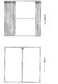
- Make adjustments As shown in FIG. 7, when raster scanning is performed to image a three-dimensional tomographic structure, only the high-speed axis direction (x direction) at the center of the scanning angle of view set in two dimensions when adjusting imaging conditions before imaging.
- the imaging conditions are adjusted while observing the tomographic images obtained by continuously scanning the image, and then the entire original scanning field angle area is raster scanned when actually capturing the tomographic image.
- the tomographic image obtained at the time of adjusting the imaging conditions is almost constant, and the morphological change of the imaging region is less likely to occur in the tomographic image.
- the shooting conditions can be easily adjusted.
- the tomographic image to be imaged is greatly curved and scanned. Since the appearance position of the imaging region in the tomographic image differs greatly depending on the position to be scanned, even if the imaging condition is optimized by adjusting the imaging condition based on the tomographic image obtained by scanning only the center position of the raster scan, the raster As long as the form of the measurement object other than the center position of the scan cannot be grasped, an appropriate focus position and reference mirror position cannot be determined.
- the present invention has been made in view of such a point, and an object thereof is to provide a tomographic imaging apparatus capable of determining the optimal imaging condition by completing the adjustment of the imaging condition in a short time. .
- the present invention splits light from a light source into measurement light and reference light and makes them incident on a target object and a reference object, and reflected by the measurement light and the reference object reflected by the target object.
- a tomographic imaging apparatus that captures a tomographic image of a target object based on interference light generated by superimposing a reference light, and scans the measurement light into a target object by two-dimensional scanning to capture a tomographic image of the target object A time required for two-dimensional scanning in the second imaging mode, and a second imaging mode in which measurement light is two-dimensionally scanned and incident on a target object and a tomographic image of the target object is captured.
- Tomographic image capturing is to provide a tomography apparatus according to claim conducted in Capture Mode (invention 1).
- the adjustment of the imaging conditions necessary for imaging the tomographic image in the first imaging mode depends on the alignment between the tomographic imaging apparatus and the eye to be inspected and the diopter of the eye to be inspected. Adjust the focus by moving the focus lens position, move the reference mirror position to generate interference light by superimposing the measurement light and the reference light, and adjust the optical path length of the measurement optical system and the reference optical system. Adjusting the reference mirror position to match, determining dispersion compensation glass to select appropriate dispersion compensation glass to compensate for refractive index dispersion that causes tomogram blurring, etc. Various adjustment operations performed before shooting are included.
- the second imaging mode is provided in which the tomographic image is captured by two-dimensional scanning in which the time required for scanning is shorter than that in the first imaging mode
- the first imaging is performed in the second imaging mode.
- the photographing conditions necessary for photographing the tomographic image in the mode the adjustment of the photographing conditions can be completed in a short time.
- the tomographic image in the second imaging mode is not a one-dimensional scan of the center position of raster scanning as in the prior art, but is performed by two-dimensional scanning, thereby covering almost the entire imaging region. Since the tomographic image can be observed while adjusting the imaging conditions, the optimal imaging conditions can be determined.
- the scanning area in the second imaging mode is an area including an attention area in the scanning area in the first imaging mode (Invention 2).
- the attention area is an area that represents a change in the form of the object to be imaged in the scanning area in the first imaging mode.
- the region of interest within the region to be scanned when tomographic imaging is performed in the first imaging mode is included in the target to be scanned in the second imaging mode. Therefore, it is possible to obtain sufficient information from the tomographic image photographed in the second photographing mode to adjust the photographing conditions necessary for photographing the tomographic image in the first photographing mode.
- the scanning region in the second photographing mode may be wider or narrower than the scanning region in the first photographing mode as long as the region of interest in the scanning region in the first photographing mode is included.
- the two-dimensional scanning in the first photographing mode is raster scanning (Invention 3).
- photography mode is a scanning which thinned out the raster scanning in the said 1st imaging
- the scanning may be performed by scanning four sides of a rectangular area including a region of interest in the scanning area in the first imaging mode (Invention 5). It may be a scan that scans one or two diagonal lines of a rectangular area including a region of interest in the scanning area (Invention 6).
- the image pickup apparatus further includes a third imaging mode in which the measurement light is one-dimensionally scanned and incident on the target object, and a tomographic image of the target object is captured, and the image is captured in the third imaging mode.
- the second adjustment operation may be performed based on the tomographic image photographed in the second photographing mode (invention 7).
- Display means for displaying a tomographic image of the target object generated based on the tomographic image generated based on the tomographic image captured in the second imaging mode in the second imaging mode;
- a first display mode for displaying only one tomographic image including a predetermined target position of the target object, and a tomographic image generated based on the tomographic image captured in the second imaging mode in order.
- Switch between 2 display modes After the first adjustment operation is performed based on the tomographic image displayed in the first display mode, the second adjustment operation is performed based on the tomographic image displayed in the second display mode. (Invention 8).
- the first adjustment operation is a dispersion compensation glass decision for selecting an appropriate dispersion compensation glass to compensate for refractive index dispersion that causes a tomographic image blur, and a diopter of the eye to be examined.
- the focus is adjusted by moving the position of the focus lens.
- the second adjustment operation refers to focus adjustment by moving the position of the focus lens according to the diopter of the eye to be examined, and generating interference light by superimposing the measurement light and the reference light.
- the reference mirror position is adjusted by moving the position of the reference mirror to match the optical path lengths of the measurement optical system and the reference optical system.
- the first adjustment operation that can be appropriately adjusted based on only one specific tomographic image and the one that is adjusted based on a plurality of tomographic images obtained by two-dimensional scanning Since the second adjustment operation that can be adjusted more appropriately can be performed separately, it is possible to determine the optimum photographing condition in a short time.
- invention 9 it is preferable to further comprise storage means for storing a tomographic image taken in the second photography mode.
- a tomographic image acquired for adjustment of imaging conditions has not been used for any purpose other than adjustment.
- tomographic image data acquired in the second imaging mode is stored. Therefore, the data can be used for correcting the alignment of a tomographic image generated from the tomographic image captured in the first imaging mode, or can be used as a thumbnail image.
- the optimal imaging conditions can be determined by completing the adjustment of the imaging conditions in a short time.
- FIG. 1 is an optical diagram showing an overall configuration of a tomographic imaging apparatus according to a first embodiment of the present invention. It is explanatory drawing which shows the scanning pattern of this imaging
- FIG. 1 is an optical diagram showing the overall configuration of a tomographic imaging apparatus according to the first embodiment of the present invention.
- the tomographic imaging apparatus according to the present embodiment captures a tomographic image of a desired region of the fundus by raster scanning using the fundus of the eye E to be imaged as an object to be imaged.
- a portion denoted by reference numeral 10 is a demultiplexing / combining optical system. This optical system emits light having a wavelength of 700 nm to 1100 nm and a temporal coherence length of about several ⁇ m to several tens of ⁇ m, for example, a superluminescent diode.
- a broadband low-coherence light source 11 made of (SLD) is provided.
- the amount of light of the low coherence light generated by the low coherence light source 11 is adjusted through the light amount adjustment mechanism 12 and is incident on the optical coupler 13 through the optical fiber 13a.
- the beam splitter 20 To the beam splitter 20. In addition, you may make it branch and multiplex using an optical circulator instead of the optical coupler 13.
- the light incident on the beam splitter 20 is divided into reference light and measurement light.
- the measurement light enters the focus lens 31 and the measurement light is focused on the fundus of the eye E.
- the measurement light focused on the fundus is reflected by the mirror 32, passes through the lens 33, and is scanned in an arbitrary direction by the x-axis scanning mirror (galvano mirror) 34 and the y-axis scanning mirror (galvano mirror) 35.
- the measurement light scanned by the x-axis and y-axis scanning mirrors 34 and 35 passes through the scan lens 36, is reflected by the dichroic mirror 37, passes through the objective lens 38 and enters the fundus oculi, and the fundus is measured by the measurement light.
- the measurement light reflected from the fundus returns to the beam splitter 20 by reversing the above path.
- the focus lens 31, mirror 32, lens 33, x-axis scanning mirror 34, y-axis scanning mirror 35, scan lens 36, dichroic mirror 37, and objective lens 38 after the beam splitter 20 are tomographic images.
- a measurement optical system 30 of the photographing apparatus is configured.
- the reference light divided by the beam splitter 20 is reflected by the mirror 41 and then passes through the objective lens dispersion compensation glass 42 and the lenses 43 and 44. After that, the light is reflected by the mirror 45 and passes through the eye dispersion compensation glass 50 that compensates the refractive index dispersion of the eye E to be examined. Then, the light is reflected by the dichroic mirror 46 to adjust the condenser lens 47 and the amount of light. It passes through the variable aperture 48 and reaches the reference mirror 49. In order to adjust the optical path length, the condensing lens 47, the variable aperture 48, and the reference mirror 49 move together in the optical axis direction as shown by a double arrow in FIG. The reference light reflected by the reference mirror 49 returns to the beam splitter 20 along the above optical path.
- the focus lens 31, the lens 33, the scan lens 36, and the objective lens 38 of the measurement optical system 30 are the lenses 43 and 44 of the reference optical system 40, the condenser lens 47, and the dispersion compensation glass 42 for the objective lens.
- each dispersion characteristic is the same or equivalent.
- the mirror 32, the x-axis scanning mirror 34, the y-axis scanning mirror 35, and the dichroic mirror 37 of the measurement optical system 30 correspond to the mirror 41, the mirror 45, the reference mirror 49, and the dichroic mirror 46 of the reference optical system 40, respectively.
- the dispersion characteristics are the same or equivalent.
- the dispersion characteristics of the eye E and the dispersion characteristics of the eye dispersion compensation glass 50 are the same or equivalent.
- the mirror 41, the objective lens dispersion compensation glass 42, the lenses 43 and 44, the mirror 45, the eye dispersion compensation glass 50, the dichroic mirror 46, the condenser lens 47, and the reference mirror 49 as a reference object
- a reference optical system 40 of the tomographic imaging apparatus is configured.
- the measurement light and the reference light that have returned to the beam splitter 20 are superimposed and become interference light, which passes through the collimator lens 14 and the optical coupler 13 and enters the spectroscope 16 via the optical fiber 13c.
- the spectroscope 16 includes a diffraction grating 16a, an imaging lens 16b, a line sensor 16c, and the like.
- the interference light is split into a spectrum corresponding to the wavelength of the low coherence light by the diffraction grating 16a and is lined by the imaging lens 16b. An image is formed on the sensor 16c.
- the signal from the line sensor 16c is subjected to signal processing including Fourier transformation by a tomographic image forming means realized by a CPU of the computer 17, and a depth signal indicating information in the depth direction (z direction) of the fundus is generated.
- the formed tomographic image (B-scan image) can be displayed on the display 18. Further, the formed tomographic image can be stored in a storage unit (not shown) in the computer 17.
- the tomographic imaging apparatus adjusts several imaging conditions in order to optimize the imaging conditions when actually capturing the tomographic image.
- the adjustment of the imaging conditions for example, the alignment of the tomographic imaging apparatus and the subject eye E that is the target object, the focus adjustment that adjusts the focus by moving the position of the focus lens 31 according to the diopter of the eye E to be examined,
- the position of the reference mirror 49 is moved so as to generate interference light by superimposing the measurement light and the reference light, thereby adjusting the reference mirror position to match the optical path lengths of the measurement optical system and the reference optical system, which causes blurring of the tomographic image.
- a dispersion compensation glass determination that selects an appropriate eye dispersion compensation glass 50 to compensate for refractive index dispersion may be mentioned.
- the tomographic imaging apparatus actually performs the preliminary imaging mode (second imaging mode) for capturing a tomographic image for adjusting the imaging conditions and after determining the optimal imaging conditions by adjusting the imaging conditions.
- the main photographing mode (first photographing mode) for photographing a tomographic image for obtaining a tomographic image of a desired region (scanning region) of the fundus can be switched.
- the tomographic imaging apparatus can capture tomographic images using different scanning patterns in the preliminary imaging mode and the main imaging mode, and can switch between the preliminary imaging mode and the main imaging mode by an imaging mode switching operation.
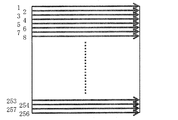
- the entire scanning area is raster scanned as shown in FIG.
- a total of 256 scans are performed in the high-speed axis direction (x-direction).
- the present embodiment is not limited to this, and is appropriately set according to the shooting target, shooting purpose, and size of the scanning area. It may be changed.
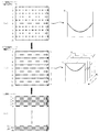
- the preliminary photographing mode as shown in FIG. 3, by increasing the scanning interval in the slow axis direction (y direction), scanning with a scanning density coarser than the scanning density in the main photographing mode, that is, raster in the main photographing mode.
- the scanning is performed by thinning out the scanning in the high speed axis direction (x direction).
- a total of 11 scans are performed in the high-speed axis direction (x direction) in the preliminary shooting mode.
- the present invention is not limited to this, and is appropriately set according to the shooting target, shooting purpose, and size of the scanning area. It may be changed. If at least the number of scans is sufficient to grasp the shape change of the target object in the scan region, the imaging conditions can be optimized appropriately.
- the pre-shooting mode shortens the time required to shoot the tomographic image for adjusting the shooting conditions by making the scanning density coarser than the main shooting mode, and the adjustment of the shooting conditions is completed in a short time. Therefore, it is desirable to set the number of scans in the preliminary shooting mode within a range of 1/2 to 1/20 of the number of scans in the main shooting mode.
- the scanning area in the preliminary photographing mode is the same area as the scanning area in the main photographing mode. Therefore, the region of interest in the scanning area in the main photographing mode is naturally included in the scanning area in the preliminary photographing mode.
- the attention area is an area representing a change in the form of the object to be imaged (the fundus of the eye E) in the scanning area in the main imaging mode.
- the selection display mode is a display method in which only one tomographic image including a predetermined target position of the target object is displayed on the display 18 among the tomographic images generated based on the tomographic image captured in the preliminary imaging mode.
- only one tomographic image generated based on a tomographic image taken by scanning of the center position in the y direction of the scanning region (scan of number 6 in FIG. 3) is repeatedly displayed.
- the continuous display mode is a display method in which tomographic images generated based on the tomographic images captured in the preliminary imaging mode are sequentially displayed on the display 18 in the present embodiment. In this embodiment, all the scans (numbers in FIG. 3) are displayed. 11 tomographic images generated based on the tomographic images taken by scanning 1 to 11 are repeatedly displayed in order.
- the adjustment of the photographing condition is divided into two stages of a first adjustment operation and a second adjustment operation, the first adjustment operation is performed using the above-described selection display mode, and the second adjustment operation is performed using the continuous display mode.
- a dispersion compensation glass decision for selecting an appropriate eye dispersion compensation glass 50 to compensate for refractive index dispersion that causes tomographic image blurring, and a focus lens according to the diopter of the eye E to be examined The focus adjustment is performed by moving the position 31 to focus.
- focus adjustment is performed by moving the position of the focus lens 31 according to the diopter of the eye E to be examined, and reference is performed to generate interference light by superimposing the measurement light and the reference light.
- Reference mirror position adjustment is performed by moving the position of the mirror 49 to match the optical path lengths of the measurement optical system and the reference optical system.
- the first adjustment operation that can be appropriately adjusted based on only one specific tomographic image and the second adjustment that can be adjusted more appropriately based on a plurality of tomographic images obtained by two-dimensional scanning. By performing the adjustment operation separately, it is possible to determine the optimum photographing condition in a short time.
- the first adjustment operation is performed in the preliminary imaging mode.
- the first adjustment operation can be appropriately adjusted based on only one specific tomographic image. Therefore, this time display 18 is set to the selected display mode, repeatedly displaying only a tomographic image T 6, which is generated based on the tomographic images taken by the scanning of the number 6.
- the display mode is switched to the continuous display mode by pressing the display mode switching button while the shooting method remains in the preliminary shooting mode.
- a second adjustment operation that can be adjusted more appropriately is performed based on a plurality of tomographic images obtained by two-dimensional scanning.
- the continuous display mode the tomographic images T 1 to T 11 are repeatedly displayed in order.
- the shooting mode switching button is pressed to switch from the preliminary shooting mode to the main shooting mode, and scanning is performed under the optimized shooting conditions.
- the entire region is scanned in a total of 256 rasters in the high-speed axis direction (x direction), and a tomographic image of the fundus of the eye E is taken.
- the selection display mode and the continuous display mode are only differences in the display method of the tomographic image, and in any case of selecting any display mode, the tomographic image of the eye E itself is captured in the preliminary imaging mode. In total, the number 1 to 11 is performed by 11 scans. That is, even when the selection display mode is set, only the scan of No. 6 is performed and only the tomographic image for generating the tomographic image T 6 is not captured, but the scans of No. 1 to 11 are performed. The tomographic images necessary for generating the tomographic images T 1 to T 11 are taken.
- the tomographic image data photographed in the preliminary photographing mode and the tomographic image generated based on the tomographic image data are stored in a storage unit (not shown) in the computer 17.
- the tomographic image acquired in the preliminary imaging mode is obtained by raster scanning several to several tens of times faster than the tomographic image acquired in the main imaging mode. It is possible to perform shooting while suppressing positional deviation due to visual movement.
- Using the tomographic images acquired in the preliminary imaging mode as a reference if the tomographic images acquired in the first imaging mode are subjected to positional deviation correction and rearranged, it is possible to obtain a high-density image excluding the influence of fixation micromotion. It becomes.
- the preliminary imaging mode for capturing a tomographic image by two-dimensional scanning having a scanning density coarser than that of the main imaging mode is provided, and the two-dimensional imaging in the preliminary imaging mode is provided. Since the time required for scanning is shorter than the time required for two-dimensional scanning in the main photographing mode, by adjusting the photographing conditions necessary for photographing the tomographic image in the main photographing mode in the preliminary photographing mode, Adjustment of shooting conditions can be completed in a short time.
- the tomographic image in the preliminary imaging mode is not a one-dimensional scan of the center position of raster scanning as in the prior art, but is performed by two-dimensional scanning with a coarse scanning density, so that almost the imaging region can be obtained. Since the tomographic image covering the whole can be observed during the adjustment of the imaging conditions, the optimal imaging conditions can be determined.
- the tomographic imaging apparatus divides the adjustment of imaging conditions into a first adjustment operation and a second adjustment operation, an adjustment imaging mode for imaging a tomographic image for performing the first adjustment operation, and a second adjustment.
- the tomographic imaging apparatus can capture a tomographic image using a different scanning pattern in each mode, and can switch between the adjustment imaging mode, the preliminary imaging mode, and the main imaging mode by an imaging mode switching operation.
- the scanning pattern in the preliminary photographing mode and the main photographing mode is the same as that in the first embodiment.
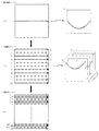
- the adjustment shooting mode is a shooting mode in which the measurement light is one-dimensionally scanned and incident on the target object, and a tomographic image of the target position of the target object is captured.
- the center position in the y direction of the scan region is set as the target position x One-dimensional scanning in the direction.
- the position of interest may be changed as appropriate according to the subject to be photographed, the purpose of photographing, and the size of the scanning region.
- the first adjustment operation can be appropriately adjusted based on only one specific tomographic image, there is no need to obtain a plurality of tomographic images by two-dimensionally scanning the scanning region.
- the time required for taking a tomographic image can be shortened by performing one-dimensional scanning of the target position in the scanning region rather than performing two-dimensional scanning of the scanning region. Therefore, in addition to the preliminary imaging mode, an adjustment imaging mode for one-dimensional scanning within the scanning region is provided, and the first adjustment operation that can be appropriately adjusted based on only one specific tomographic image is the adjustment imaging mode.
- the second adjustment operation that can be adjusted more appropriately based on a plurality of tomographic images obtained by scanning is performed separately in the preliminary imaging mode, so that the optimal imaging conditions can be determined in a short time. .
- the display method in the preliminary shooting mode is assumed to be the continuous display mode.
- the first adjustment operation is first performed in the adjustment shooting mode.
- a tomographic image Tc generated based on a tomographic image captured by scanning the center position C in the y direction of the scanning region in the x direction is repeatedly displayed on the display 18.
- the shooting mode switching button is pressed to switch from the adjustment shooting mode to the preliminary shooting mode, and the display 18 is repeatedly displayed in order.
- the second adjustment operation is performed while confirming the tomographic images T 1 to T 11 .
- the shooting mode switching button is pressed again to switch from the preliminary shooting mode to the main shooting mode.
- a total of 256 raster scans are performed on the entire scanning region in the high-speed axis direction (x direction), and a tomographic image of the fundus of the eye E is taken.
- the first adjustment operation that can be appropriately adjusted based on only one specific tomographic image is performed in the adjustment imaging mode, and obtained by two-dimensional scanning.
- the second adjustment operation in the preliminary adjustment mode which can be adjusted more appropriately by adjusting based on a plurality of tomographic images, it is possible to determine the optimum imaging condition in a short time.
- the tomographic imaging apparatus captures a tomographic image of the fundus by raster scanning, but the present invention is not limited to this, and spiral scanning or other scanning methods may be employed. .
- scanning is performed by thinning out the scanning in the high-speed axis direction (x direction) of the raster scanning in the main photographing mode in the preliminary photographing mode, but the present invention is not limited to this. It suffices if the time required for two-dimensional scanning is shorter than the time required for two-dimensional scanning in the main photographing mode. For example, the scanning density is made the same as that in the main photographing mode, and the scanning area is made narrower than in the main photographing mode. Thus, the time required for two-dimensional scanning in the preliminary photographing mode may be shortened.
- the scanning area of the preliminary photographing mode is wider than that of the main photographing mode, if the time required for two-dimensional scanning in the preliminary photographing mode is shortened by increasing the scanning density, this is also permitted.
- the scanning area in the pre-shooting mode is set to be different from the main shooting mode, the region of interest in the scanning area in the main shooting mode is included in the scanning area in the pre-shooting mode.
- another scanning pattern may be adopted in the preliminary photographing mode.
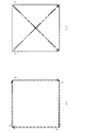
- a scanning pattern in which four sides of a rectangular region including a region of interest in a scanning region to be subjected to raster scanning in the main photographing mode may be used.
- it may be a scanning pattern that scans one or two diagonal lines of a rectangular region including a region of interest in a scanning region to be subjected to raster scanning in the main photographing mode, or a combination thereof. It may be a scanning pattern.
- the scanning direction in the main photographing mode and the scanning direction in the preliminary photographing mode may be orthogonal. Even with such a scanning pattern, it is possible to capture a tomographic image representative of the shape change of the target object in the scanning region, and therefore, it can be adopted as a scanning pattern in the preliminary imaging mode.
Landscapes
- Health & Medical Sciences (AREA)
- Life Sciences & Earth Sciences (AREA)
- Physics & Mathematics (AREA)
- Engineering & Computer Science (AREA)
- General Health & Medical Sciences (AREA)
- Medical Informatics (AREA)
- Surgery (AREA)
- Ophthalmology & Optometry (AREA)
- Biomedical Technology (AREA)
- Heart & Thoracic Surgery (AREA)
- Veterinary Medicine (AREA)
- Molecular Biology (AREA)
- Biophysics (AREA)
- Animal Behavior & Ethology (AREA)
- Public Health (AREA)
- Nuclear Medicine, Radiotherapy & Molecular Imaging (AREA)
- Radiology & Medical Imaging (AREA)
- General Physics & Mathematics (AREA)
- Signal Processing (AREA)
- Eye Examination Apparatus (AREA)
Abstract
Description
以下、本発明の第1実施形態を図面に基づいて詳細に説明する。
次に、本発明の第2実施形態を図面に基づいて詳細に説明する。第2実施形態に係る断層像撮影装置の全体構成は第1実施形態に係る断層像撮影装置と同一であるため、光学系その他の説明は省略する。また、第1実施形態と同じ素子、部品、装置については同じ符号を使用し、同じ用語は同じ意味を持つものとして使用する。以下、第1実施形態に係る断層像撮影装置と異なる点について説明する。
10 分波/合波光学系
11 低コヒーレンス光源
12 光量調整機構
13 光カプラ
14 コリメートレンズ
20 ビームスプリッタ
30 測定光学系
31 フォーカスレンズ
34 x軸走査ミラー
35 y軸走査ミラー
36 スキャンレンズ
37 ダイクロイックミラー
38 対物レンズ
40 参照光学系
42 対物レンズ用分散補償ガラス
46 ダイクロイックミラー
47 集光レンズ
48 可変アパーチャ
49 参照ミラー
50 被検眼分散補償ガラス
Claims (9)
- 光源からの光を測定光と参照光に分割して対象物体と参照物体に入射させ、対象物体で反射された測定光と参照物体で反射された参照光を重畳させて生成される干渉光に基づき対象物体の断層像を撮影する断層像撮影装置であって、
測定光を二次元走査して対象物体に入射させ、対象物体の断層像を撮影する第1撮影モードと、
測定光を二次元走査して対象物体に入射させ、対象物体の断層像を撮影する第2撮影モードと、を備え、
前記第2撮影モードにおける二次元走査に要する時間が、前記第1撮影モードにおける二次元走査に要する時間よりも短く、
前記第2撮影モードで撮影された断層像に基づいて、前記第1撮影モードで断層像の撮影をするために必要な撮影条件の調整を行った後、前記第1撮影モードで断層像の撮影が行われることを特徴とする断層像撮影装置。 - 前記第2撮影モードにおける走査領域が、前記第1撮影モードにおける走査領域中の注目領域を含む領域であることを特徴とする、請求項1に記載の断層像撮影装置。
- 前記第1撮影モードにおける二次元走査がラスタ走査であることを特徴とする、請求項1又は2に記載の断層像撮影装置。
- 前記第2撮影モードにおける二次元走査が、前記第1撮影モードにおけるラスタ走査を間引きした走査であることを特徴とする、請求項3に記載の断層像撮影装置。
- 前記第2撮影モードにおける二次元走査が、前記第1撮影モードにおける走査領域中の注目領域を含む矩形領域の4辺を走査する走査であることを特徴とする、請求項1~3のいずれか1項に記載の断層像撮影装置。
- 前記第2撮影モードにおける二次元走査が、前記第1撮影モードにおける走査領域中の注目領域を含む矩形領域の1本あるいは2本の対角線を走査する走査であることを特徴とする、請求項1~3のいずれか1項に記載の断層像撮影装置。
- 測定光を一次元走査して対象物体に入射させ、対象物体の断層像を撮影する第3撮影モードを更に備え、
前記第3撮影モードで撮影された断層像に基づいて第1調整操作を行った後、前記第2撮影モードで撮影された断層像に基づいて第2調整操作が行われることを特徴とする、請求項4に記載の断層像撮影装置。 - 撮影された断層像に基づいて生成された対象物体の断層画像を表示する表示手段を更に備え、
前記表示手段が、前記第2撮影モードにおいて、前記第2撮影モードで撮影された断層像に基づいて生成された断層画像のうち、対象物体の所定の注目位置を含む一の断層画像のみを表示する第1表示モードと、前記第2撮影モードで撮影された断層像に基づいて生成された断層画像を順に表示する第2表示モードとを切り替え可能に構成されており、
前記第1表示モードで表示された断層画像に基づいて第1調整操作を行った後、前記第2表示モードで表示された断層画像に基づいて第2調整操作が行われることを特徴とする、請求項4に記載の断層像撮影装置。 - 前記第2撮影モードで撮影された断層像を記憶する記憶手段を更に備えることを特徴とする、請求項1~8のいずれか1項に記載の断層像撮影装置。
Priority Applications (3)
| Application Number | Priority Date | Filing Date | Title |
|---|---|---|---|
| EP15814335.4A EP3165151A4 (en) | 2014-07-01 | 2015-06-30 | Tomography device |
| US15/322,151 US10219692B2 (en) | 2014-07-01 | 2015-06-30 | Tomographic image capturing device |
| JP2016531370A JP6557229B2 (ja) | 2014-07-01 | 2015-06-30 | 断層像撮影装置 |
Applications Claiming Priority (2)
| Application Number | Priority Date | Filing Date | Title |
|---|---|---|---|
| JP2014136348 | 2014-07-01 | ||
| JP2014-136348 | 2014-07-01 |
Publications (1)
| Publication Number | Publication Date |
|---|---|
| WO2016002740A1 true WO2016002740A1 (ja) | 2016-01-07 |
Family
ID=55019272
Family Applications (1)
| Application Number | Title | Priority Date | Filing Date |
|---|---|---|---|
| PCT/JP2015/068755 WO2016002740A1 (ja) | 2014-07-01 | 2015-06-30 | 断層像撮影装置 |
Country Status (4)
| Country | Link |
|---|---|
| US (1) | US10219692B2 (ja) |
| EP (1) | EP3165151A4 (ja) |
| JP (2) | JP6557229B2 (ja) |
| WO (1) | WO2016002740A1 (ja) |
Cited By (3)
| Publication number | Priority date | Publication date | Assignee | Title |
|---|---|---|---|---|
| JP2018140006A (ja) * | 2017-02-28 | 2018-09-13 | キヤノン株式会社 | 撮像装置、撮像装置の制御方法およびプログラム |
| JP2019171165A (ja) * | 2014-07-01 | 2019-10-10 | 興和株式会社 | 撮影装置 |
| WO2021256132A1 (ja) | 2020-06-15 | 2021-12-23 | 株式会社トプコン | 眼科装置、眼科装置の制御方法、及びプログラム |
Families Citing this family (1)
| Publication number | Priority date | Publication date | Assignee | Title |
|---|---|---|---|---|
| WO2016017664A1 (ja) | 2014-07-30 | 2016-02-04 | 興和株式会社 | 断層像撮影装置 |
Citations (1)
| Publication number | Priority date | Publication date | Assignee | Title |
|---|---|---|---|---|
| JP2012192260A (ja) * | 2012-07-13 | 2012-10-11 | Canon Inc | 断層像撮像装置および断層撮像方法、プログラム |
Family Cites Families (11)
| Publication number | Priority date | Publication date | Assignee | Title |
|---|---|---|---|---|
| JP4996917B2 (ja) * | 2006-12-26 | 2012-08-08 | 株式会社トプコン | 光画像計測装置及び光画像計測装置を制御するプログラム |
| JP4971863B2 (ja) * | 2007-04-18 | 2012-07-11 | 株式会社トプコン | 光画像計測装置 |
| JP4971864B2 (ja) | 2007-04-18 | 2012-07-11 | 株式会社トプコン | 光画像計測装置及びそれを制御するプログラム |
| WO2010117386A1 (en) * | 2009-04-10 | 2010-10-14 | Doheny Eye Institute | Ophthalmic testing methods, devices and systems |
| JP5627260B2 (ja) | 2009-05-22 | 2014-11-19 | キヤノン株式会社 | 撮像装置および撮像方法 |
| JP5017328B2 (ja) * | 2009-08-11 | 2012-09-05 | キヤノン株式会社 | 断層像撮像装置およびその制御方法、プログラム、記憶媒体 |
| FR2962531B1 (fr) | 2010-07-08 | 2014-01-17 | Lltech Inc | Methode et dispositif d'imagerie tridimensionnelle par microscopie interferentielle plein champ |
| US9101294B2 (en) * | 2012-01-19 | 2015-08-11 | Carl Zeiss Meditec, Inc. | Systems and methods for enhanced accuracy in OCT imaging of the cornea |
| US9192294B2 (en) | 2012-05-10 | 2015-11-24 | Carl Zeiss Meditec, Inc. | Systems and methods for faster optical coherence tomography acquisition and processing |
| JP6460618B2 (ja) * | 2013-01-31 | 2019-01-30 | キヤノン株式会社 | 光干渉断層撮像装置およびその制御方法 |
| EP3165151A4 (en) * | 2014-07-01 | 2018-03-28 | KOWA Co., Ltd. | Tomography device |
-
2015
- 2015-06-30 EP EP15814335.4A patent/EP3165151A4/en not_active Withdrawn
- 2015-06-30 WO PCT/JP2015/068755 patent/WO2016002740A1/ja active Application Filing
- 2015-06-30 US US15/322,151 patent/US10219692B2/en not_active Expired - Fee Related
- 2015-06-30 JP JP2016531370A patent/JP6557229B2/ja active Active
-
2019
- 2019-07-11 JP JP2019129264A patent/JP2019171165A/ja active Pending
Patent Citations (1)
| Publication number | Priority date | Publication date | Assignee | Title |
|---|---|---|---|---|
| JP2012192260A (ja) * | 2012-07-13 | 2012-10-11 | Canon Inc | 断層像撮像装置および断層撮像方法、プログラム |
Non-Patent Citations (1)
| Title |
|---|
| See also references of EP3165151A4 * |
Cited By (3)
| Publication number | Priority date | Publication date | Assignee | Title |
|---|---|---|---|---|
| JP2019171165A (ja) * | 2014-07-01 | 2019-10-10 | 興和株式会社 | 撮影装置 |
| JP2018140006A (ja) * | 2017-02-28 | 2018-09-13 | キヤノン株式会社 | 撮像装置、撮像装置の制御方法およびプログラム |
| WO2021256132A1 (ja) | 2020-06-15 | 2021-12-23 | 株式会社トプコン | 眼科装置、眼科装置の制御方法、及びプログラム |
Also Published As
| Publication number | Publication date |
|---|---|
| JPWO2016002740A1 (ja) | 2017-04-27 |
| JP6557229B2 (ja) | 2019-08-07 |
| US10219692B2 (en) | 2019-03-05 |
| EP3165151A1 (en) | 2017-05-10 |
| EP3165151A4 (en) | 2018-03-28 |
| JP2019171165A (ja) | 2019-10-10 |
| US20170135575A1 (en) | 2017-05-18 |
Similar Documents
| Publication | Publication Date | Title |
|---|---|---|
| JP5054072B2 (ja) | 光断層画像撮像装置 | |
| US9033500B2 (en) | Optical coherence tomography and method thereof | |
| JP6062688B2 (ja) | 眼科装置、眼科装置の制御方法、およびプログラム | |
| JP5610706B2 (ja) | 撮像装置および撮像方法 | |
| JP2019171165A (ja) | 撮影装置 | |
| JP2011172822A (ja) | 光断層像撮影装置 | |
| KR20130086969A (ko) | 광 간섭 단층 촬상 장치, 광 간섭 단층 촬상 장치 제어 방법 및 저장 매체 | |
| JP2019107569A (ja) | 眼底撮影装置 | |
| JP2011212203A (ja) | 撮像装置及び撮像方法 | |
| WO2019117036A1 (ja) | 撮像装置及びその制御方法 | |
| JP7368581B2 (ja) | 眼科装置、及び眼科情報処理装置 | |
| JP6807442B2 (ja) | 眼底撮影装置 | |
| JP6918581B2 (ja) | 制御装置、断層像撮影システム、制御方法、及びプログラム | |
| JP5828811B2 (ja) | 撮像装置及びその制御方法 | |
| JP6898716B2 (ja) | 光断層撮像装置 | |
| JP5990932B2 (ja) | 眼光断層画像撮像装置 | |
| JP5987355B2 (ja) | 眼光断層画像撮像装置 | |
| JP5649679B2 (ja) | 光干渉断層撮像装置、光干渉断層撮像装置の制御方法、およびプログラム | |
| JP2018171326A (ja) | 断層画像撮影装置、および断層画像撮影プログラム | |
| JP6932581B2 (ja) | 眼科装置、情報処理装置、情報処理方法及びプログラム | |
| JP2016077454A (ja) | 眼科装置 | |
| JP2016067588A (ja) | 光干渉断層撮影装置およびその制御方法 | |
| JP2020048688A (ja) | 眼科装置および眼科装置の制御方法 | |
| JP2019042377A (ja) | 光干渉断層撮影装置、光干渉断層撮影装置の制御方法及びプログラム | |
| JP2019054981A (ja) | 検査装置、該検査装置の制御方法、及びプログラム |
Legal Events
| Date | Code | Title | Description |
|---|---|---|---|
| 121 | Ep: the epo has been informed by wipo that ep was designated in this application |
Ref document number: 15814335 Country of ref document: EP Kind code of ref document: A1 |
|
| ENP | Entry into the national phase |
Ref document number: 2016531370 Country of ref document: JP Kind code of ref document: A |
|
| WWE | Wipo information: entry into national phase |
Ref document number: 15322151 Country of ref document: US |
|
| NENP | Non-entry into the national phase |
Ref country code: DE |
|
| REEP | Request for entry into the european phase |
Ref document number: 2015814335 Country of ref document: EP |
|
| WWE | Wipo information: entry into national phase |
Ref document number: 2015814335 Country of ref document: EP |