WO2015199036A1 - 飲料水供給装置 - Google Patents
飲料水供給装置 Download PDFInfo
- Publication number
- WO2015199036A1 WO2015199036A1 PCT/JP2015/067909 JP2015067909W WO2015199036A1 WO 2015199036 A1 WO2015199036 A1 WO 2015199036A1 JP 2015067909 W JP2015067909 W JP 2015067909W WO 2015199036 A1 WO2015199036 A1 WO 2015199036A1
- Authority
- WO
- WIPO (PCT)
- Prior art keywords
- water
- water quality
- unit
- quality improvement
- clean
- Prior art date
- Legal status (The legal status is an assumption and is not a legal conclusion. Google has not performed a legal analysis and makes no representation as to the accuracy of the status listed.)
- Ceased
Links
- 0 C(*1)C=*2*1=C2 Chemical compound C(*1)C=*2*1=C2 0.000 description 1
Images



Classifications
-
- B—PERFORMING OPERATIONS; TRANSPORTING
- B67—OPENING, CLOSING OR CLEANING BOTTLES, JARS OR SIMILAR CONTAINERS; LIQUID HANDLING
- B67D—DISPENSING, DELIVERING OR TRANSFERRING LIQUIDS, NOT OTHERWISE PROVIDED FOR
- B67D1/00—Apparatus or devices for dispensing beverages on draught
- B67D1/07—Cleaning beverage-dispensing apparatus
-
- B—PERFORMING OPERATIONS; TRANSPORTING
- B67—OPENING, CLOSING OR CLEANING BOTTLES, JARS OR SIMILAR CONTAINERS; LIQUID HANDLING
- B67D—DISPENSING, DELIVERING OR TRANSFERRING LIQUIDS, NOT OTHERWISE PROVIDED FOR
- B67D1/00—Apparatus or devices for dispensing beverages on draught
- B67D1/08—Details
-
- B—PERFORMING OPERATIONS; TRANSPORTING
- B67—OPENING, CLOSING OR CLEANING BOTTLES, JARS OR SIMILAR CONTAINERS; LIQUID HANDLING
- B67D—DISPENSING, DELIVERING OR TRANSFERRING LIQUIDS, NOT OTHERWISE PROVIDED FOR
- B67D3/00—Apparatus or devices for controlling flow of liquids under gravity from storage containers for dispensing purposes
-
- C—CHEMISTRY; METALLURGY
- C02—TREATMENT OF WATER, WASTE WATER, SEWAGE, OR SLUDGE
- C02F—TREATMENT OF WATER, WASTE WATER, SEWAGE, OR SLUDGE
- C02F1/00—Treatment of water, waste water, or sewage
- C02F1/28—Treatment of water, waste water, or sewage by sorption
-
- C—CHEMISTRY; METALLURGY
- C02—TREATMENT OF WATER, WASTE WATER, SEWAGE, OR SLUDGE
- C02F—TREATMENT OF WATER, WASTE WATER, SEWAGE, OR SLUDGE
- C02F1/00—Treatment of water, waste water, or sewage
- C02F1/44—Treatment of water, waste water, or sewage by dialysis, osmosis or reverse osmosis
-
- F—MECHANICAL ENGINEERING; LIGHTING; HEATING; WEAPONS; BLASTING
- F25—REFRIGERATION OR COOLING; COMBINED HEATING AND REFRIGERATION SYSTEMS; HEAT PUMP SYSTEMS; MANUFACTURE OR STORAGE OF ICE; LIQUEFACTION SOLIDIFICATION OF GASES
- F25D—REFRIGERATORS; COLD ROOMS; ICE-BOXES; COOLING OR FREEZING APPARATUS NOT OTHERWISE PROVIDED FOR
- F25D11/00—Self-contained movable devices, e.g. domestic refrigerators
Definitions
- a chilled water tank is arranged in the upper part of the inside of the chilled water machine main body, and the inside of the chilled water tank is partitioned into a water storage part and a chilled water part by a partition member.
- a cartridge in which activated carbon is wrapped and stored in a nonwoven fabric is provided on the lower surface of the partition member, and tap water is filtered by this cartridge and supplied as drinking water.
- the clean water storage section downstream of the water quality improvement section is also in communication with the atmosphere, the pressure on the outlet side of the water quality improvement section may suddenly become negative when the water supply section is opened. Absent. Accordingly, a large pressure is not applied to the upper part of the at least one water quality improving material, and a lower part of the at least one water quality improving material is not sucked by the large pressure. Therefore, the water in the water quality improving material flows down at the flow speed due to its own weight, and does not flow down at a speed higher than the flow speed.
- the desired flow rate is determined based on the total amount of the water quality improvement material, and for the latter (filtration system filtration material), the area and thickness are determined. Any one of these may be changed to obtain a desired flow rate. Therefore, the design of the water quality improvement unit is natural and easy.
- the drinking water supply apparatus of one aspect of the present invention since water passes through the water quality improving material at a constant flow rate, it is possible to stably realize appropriate water quality improvement.
- the drinking water supply device is installed on the floor F.
- the housing 201 of the drinking water supply device has a vertically long, substantially rectangular parallelepiped shape that bulges slightly forward.
- the recessed portion 211 is provided with known water supply cocks (175, 170) for hot water and cold water as a water supply section.
- the surface located below the water supply cock (175, 170) and below the concave portion 211 is configured as a drinking cup pedestal 214.
- the water supply cock (175, 170) is provided with a lever body 215 that is curved and extends downward.
- the water supply cocks (175, 170) are configured to be opened when the lever body 215 is pushed from the front.
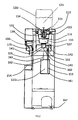
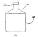
- raw water 121 is stored inside the bottle 120.
- the liquid supply cap 122 has a sealing valve 123.
- a force by the elastic member 124 acts on the sealing valve 123 so that the bottle 120 alone is in a sealed state.
- the opening of the bottle 120 is closed by the sealing valve 123. Therefore, the liquid does not leak in the bottle 120 as a whole in a single state.
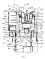
- the dust and microorganisms are adsorbed and collected by the mesh 132 and the activated carbon 137 and deodorized.
- the collection target of the activated carbon 137 includes chalk, trihalomethane, organic substances, odorous substances, and chlorinated organic substances.
- As the activated carbon 137 natural fibers derived from plants or synthetic fibers derived from minerals, or fibrous activated carbon prepared by carbonizing a mixture of natural fibers and synthetic fibers and using a binder are suitable.
- Biological minerals may be added to the activated carbon 137. Biological minerals can be supplied as isotonic solutions with mineral components (K, Ca, Na, Mg) in a balance very close to the body fluids of the human body.
- the water quality improvement water 121a is subjected to the third water quality improvement by the hollow fiber membrane 141 which is the third section of the water quality improvement section.
- the hollow fiber membrane 141 is formed by accumulating and fixing hollow fibers. One end of the hollow fiber (one end of the hollow fiber membrane 141) is exposed, and water molecules absorbed from the surface of the hollow fiber are released from the other open end (the other end of the hollow fiber). Filtering with a fineness of about 0.3 microns is possible.
- a portion indicated by reference numeral 144 is an inner screw portion of the guide case 142.
- the water quality improving water 121a passes at a permeation speed defined by the hollow fiber membrane 141 and falls downward, and is discharged from the lower end portion 143 of the hollow fiber membrane 141.
- the lower end portion 143 becomes a discharge portion (a discharge portion of the water quality improvement portion) that is a portion where water with improved water quality is naturally dropped and discharged.
- the hollow fiber membrane 141 an aggregate of fibers having a pore diameter of 0.01 to 0.09 ⁇ m and slit-like ultrafine holes provided in the peripheral wall portion is preferable.
- the water quality improvement water 121a flowing out from the opening 116 is filtered by the water quality improvement material, thereby generating a distribution resistance.
- the mesh 132, the activated carbon 137, and the hollow fiber membrane 141 correspond to an example of a water quality improving material. For this reason, water tends to stay in the water quality improvement system.
- there is a relationship such as “amount of inflow of water quality improving water 121a from the opening 116 >> amount of water quality improving water 121a permeating through the hollow fiber membrane 141 of the third section”. Therefore, the water level in the water quality improvement system gradually rises, and when the water level of the water quality improvement water 121a rises to the full water position 117, the outflow from the opening 116 is temporarily suppressed.
- the full water position determination unit defines the full water position 117.
- the full water position 117 is determined by the bottle guide 112 having the bottom part 113 and the position of the bottom part 113 in the introduction part 131 when the water quality improvement part is coupled by the coupling part 136.
- the clean water 121b after the water quality improvement is introduced and stored in the clean water storage section.
- the clean water reservoir is open to the atmosphere via the communication pipe 154 and the communication hole 134.
- a filter (not shown) is provided in the upper part (upper inlet) of the communication pipe 154, and the clean water reservoir communicates with the atmosphere via the filter.
- the filter allows clean air to communicate with the clean water reservoir.
- the clean water storage unit has a structure in which one region is divided into two vertically by a partition plate 151.
- the upper room is the storage tank 150
- the lower room is the storage tank cooling room 155.
- the liquid level position 152 is gradually raised.
- the state in which the water quality improvement water 121a is falling from the hollow fiber membrane 141 as the third section as the clean water 121b in the storage tank 150 is defined as pattern 1 (atmospheric discharge), and the force relationship that only atmospheric pressure acts The state is determined.
- a hot water tank 160 is further provided below the clean water reservoir.
- a clean water inlet 156 for introducing clean water 121b is provided in the vicinity of the partition plate 151, and a supply pipe 153 is provided so that liquid above the storage tank cooling chamber 155 can be introduced.
- the lower end of the supply pipe 153 is close to the lower part 161 of the hot water tank 160.
- a hot water supply pipe 163 (partially not shown) is connected to the upper part 162 of the hot water tank 160 for hot water extraction.
- the hot water supply pipe 163 is also connected to a hot water cock 175. In the state of FIG. 3, the hot water cock 175 is closed, and the clean water 121b hardly flows into the hot water tank 160 filled with air.
- the clean water 121b in the storage tank 150 flows into the hot water tank 160 through the supply pipe 153 and fills the hot water tank 160.
- the liquid surface position 152 that was in the full water position 117 of the storage tank 150 is temporarily lowered significantly because the clean water 121b is supplied by the volume of the hot water tank 160. For this reason, the balance is broken, and the clean water 121b flows out from the opening 116 again, and continues until the liquid level position 152 returns to the full water position 117 according to the above-described patterns 1 and 2.
- the hot water tank 160 is provided with a heating unit and a heating control unit (not shown), and the clean water 121b in the hot water tank 160 is maintained at a desired temperature by the heating unit and the heating control unit.
- the clean water 121b accumulated in the storage tank cooling chamber 155 becomes cold water having a desired temperature by the refrigerator 167 installed below the main body.
- a refrigerant transmission pipe extends from the refrigerator 167, and the refrigerant transmission pipe is wound around the outer periphery of the storage tank cooling chamber 155 to form a cooling unit 169.
- the clean water 121b accumulated in the storage tank cooling chamber 155 is cooled via the cooling unit 169.
- the refrigerator 167 is controlled by a sensor (not shown) attached to the storage tank cooling chamber 155 and a temperature control unit (not shown).
- the bottom of the storage tank cooling chamber 155 and the cold water cock 170 are connected by a cold water supply pipe (not shown), and the cold water cock 170 is opened to take out the cold water stored at a desired temperature.
- the cooled clean water 121b is cooled from the bottom of the storage tank cooling chamber 155 through a cold water discharge pipe (not shown) due to a water head difference between the full water position 117 and the position (height) of the cold water cock 170. Supplied from the cold water cock 170.
- the extraction of hot water is as follows. Specifically, since the hot water supply pipe 163 (not shown in part) is connected from the hot water tank 160 to the hot water cock 175, when the hot water cock 175 is opened, the full water position 117 and the positions of the hot water cock 175 (specifically The hot water cock 175 supplies clean water 121b that has become hot water due to a difference in water head between the hot water cock 175 and the cold water cock.
- the same amount of clean water 121b as the supplied hot water is supplied from the storage tank 150 to the hot water tank 160 through the supply pipe 153.
- the reason why the supply pipe 153 is arranged at the bottom and the hot water supply pipe 163 is arranged at the top is to introduce the clean water 121b at room temperature, so that the supplementary water is taken out at the bottom, taking into account thermal convection. This is because the upper part is preferable.
Landscapes
- Engineering & Computer Science (AREA)
- Chemical & Material Sciences (AREA)
- Mechanical Engineering (AREA)
- Life Sciences & Earth Sciences (AREA)
- Hydrology & Water Resources (AREA)
- Environmental & Geological Engineering (AREA)
- Water Supply & Treatment (AREA)
- Organic Chemistry (AREA)
- Combustion & Propulsion (AREA)
- Physics & Mathematics (AREA)
- Thermal Sciences (AREA)
- General Engineering & Computer Science (AREA)
- Water Treatment By Sorption (AREA)
- Devices For Dispensing Beverages (AREA)
- Separation Using Semi-Permeable Membranes (AREA)
- Devices That Are Associated With Refrigeration Equipment (AREA)
Priority Applications (2)
| Application Number | Priority Date | Filing Date | Title |
|---|---|---|---|
| CN201580031171.3A CN106660775B (zh) | 2014-06-23 | 2015-06-22 | 饮用水供给装置 |
| KR1020167034424A KR101938465B1 (ko) | 2014-06-23 | 2015-06-22 | 음료수 공급장치 |
Applications Claiming Priority (2)
| Application Number | Priority Date | Filing Date | Title |
|---|---|---|---|
| JP2014127992A JP6336339B2 (ja) | 2014-06-23 | 2014-06-23 | 飲料水供給装置 |
| JP2014-127992 | 2014-06-23 |
Publications (1)
| Publication Number | Publication Date |
|---|---|
| WO2015199036A1 true WO2015199036A1 (ja) | 2015-12-30 |
Family
ID=54938118
Family Applications (1)
| Application Number | Title | Priority Date | Filing Date |
|---|---|---|---|
| PCT/JP2015/067909 Ceased WO2015199036A1 (ja) | 2014-06-23 | 2015-06-22 | 飲料水供給装置 |
Country Status (5)
| Country | Link |
|---|---|
| JP (1) | JP6336339B2 (cg-RX-API-DMAC7.html) |
| KR (1) | KR101938465B1 (cg-RX-API-DMAC7.html) |
| CN (1) | CN106660775B (cg-RX-API-DMAC7.html) |
| TW (1) | TWI616627B (cg-RX-API-DMAC7.html) |
| WO (1) | WO2015199036A1 (cg-RX-API-DMAC7.html) |
Families Citing this family (5)
| Publication number | Priority date | Publication date | Assignee | Title |
|---|---|---|---|---|
| JP6430731B2 (ja) * | 2014-07-02 | 2018-11-28 | ビクトリージャパン株式会社 | 飲料水供給装置 |
| JP6280007B2 (ja) * | 2014-09-10 | 2018-02-14 | ビクトリージャパン株式会社 | 飲料水供給装置 |
| JP6470982B2 (ja) * | 2015-01-26 | 2019-02-13 | パーパス株式会社 | ウォーターサーバー |
| JP2019147562A (ja) * | 2016-07-06 | 2019-09-05 | 株式会社 美研 | 浄水ボトル及びそれを用いたウォーターサーバー |
| KR20250125646A (ko) * | 2024-02-15 | 2025-08-22 | 주식회사 위닉스 | 정수기 |
Citations (5)
| Publication number | Priority date | Publication date | Assignee | Title |
|---|---|---|---|---|
| US5486285A (en) * | 1993-06-10 | 1996-01-23 | The Clorox Company | Air inlet valve for water cooler |
| JP2007136304A (ja) * | 2005-11-16 | 2007-06-07 | Fnet Planning:Kk | 浄水フィルタ、浄水カートリッジ、ウォーターサーバータンク及びウォーターサーバーシステム |
| US20110284585A1 (en) * | 2009-01-20 | 2011-11-24 | Roger Stewart-Barnett | Water dispenser |
| JP3174445U (ja) * | 2012-01-06 | 2012-03-22 | 芙蓉商事株式会社 | ウオーターサーバー |
| JP2012071900A (ja) * | 2012-01-20 | 2012-04-12 | Fujiyama Corp | 飲料水用サーバー |
Family Cites Families (7)
| Publication number | Priority date | Publication date | Assignee | Title |
|---|---|---|---|---|
| JPH05149663A (ja) | 1991-11-27 | 1993-06-15 | Toshiba Corp | 冷水機 |
| TW579907U (en) * | 2003-06-26 | 2004-03-11 | Guei-Tang Jang | Filtering device for drinking fountain |
| KR101094567B1 (ko) * | 2006-02-14 | 2011-12-19 | 미츠비시 레이온 클린스이 가부시키가이샤 | 음수기 |
| CN102762487A (zh) * | 2010-02-24 | 2012-10-31 | 目的株式会社 | 饮用水供应装置 |
| JP6430731B2 (ja) * | 2014-07-02 | 2018-11-28 | ビクトリージャパン株式会社 | 飲料水供給装置 |
| JP2016033020A (ja) * | 2014-07-31 | 2016-03-10 | ビクトリージャパン株式会社 | 飲料水供給装置 |
| JP6280007B2 (ja) * | 2014-09-10 | 2018-02-14 | ビクトリージャパン株式会社 | 飲料水供給装置 |
-
2014
- 2014-06-23 JP JP2014127992A patent/JP6336339B2/ja active Active
-
2015
- 2015-05-28 TW TW104117094A patent/TWI616627B/zh active
- 2015-06-22 CN CN201580031171.3A patent/CN106660775B/zh not_active Expired - Fee Related
- 2015-06-22 KR KR1020167034424A patent/KR101938465B1/ko active Active
- 2015-06-22 WO PCT/JP2015/067909 patent/WO2015199036A1/ja not_active Ceased
Patent Citations (5)
| Publication number | Priority date | Publication date | Assignee | Title |
|---|---|---|---|---|
| US5486285A (en) * | 1993-06-10 | 1996-01-23 | The Clorox Company | Air inlet valve for water cooler |
| JP2007136304A (ja) * | 2005-11-16 | 2007-06-07 | Fnet Planning:Kk | 浄水フィルタ、浄水カートリッジ、ウォーターサーバータンク及びウォーターサーバーシステム |
| US20110284585A1 (en) * | 2009-01-20 | 2011-11-24 | Roger Stewart-Barnett | Water dispenser |
| JP3174445U (ja) * | 2012-01-06 | 2012-03-22 | 芙蓉商事株式会社 | ウオーターサーバー |
| JP2012071900A (ja) * | 2012-01-20 | 2012-04-12 | Fujiyama Corp | 飲料水用サーバー |
Also Published As
| Publication number | Publication date |
|---|---|
| JP6336339B2 (ja) | 2018-06-06 |
| TWI616627B (zh) | 2018-03-01 |
| TW201604505A (zh) | 2016-02-01 |
| KR101938465B1 (ko) | 2019-01-14 |
| KR20170020341A (ko) | 2017-02-22 |
| CN106660775B (zh) | 2018-12-28 |
| JP2016008051A (ja) | 2016-01-18 |
| CN106660775A (zh) | 2017-05-10 |
Similar Documents
| Publication | Publication Date | Title |
|---|---|---|
| JP6336339B2 (ja) | 飲料水供給装置 | |
| JP5284639B2 (ja) | 自重濾過型飲水器 | |
| EP2969969B1 (en) | Device for water filtration | |
| US20170050133A1 (en) | Water filter cartridge with air conduction | |
| US10940411B2 (en) | Water filter cartridge with air conduction | |
| CN104548299A (zh) | 一种呼吸机及湿化器 | |
| JP2016033020A (ja) | 飲料水供給装置 | |
| JP2016033020A5 (cg-RX-API-DMAC7.html) | ||
| JP5721800B2 (ja) | 加湿器フィルター | |
| US9216894B2 (en) | Drinking water server | |
| JP6430731B2 (ja) | 飲料水供給装置 | |
| KR101271976B1 (ko) | 정수 카트리지 및 정수기 | |
| JP6280007B2 (ja) | 飲料水供給装置 | |
| JP4705860B2 (ja) | 飲水器 | |
| JP2016013857A5 (cg-RX-API-DMAC7.html) | ||
| US20230295008A1 (en) | Filter assemblies and methods of filtering with the same | |
| JP2011152492A (ja) | 浄水器 | |
| JP2006305516A (ja) | 自重濾過装置、自重濾過用フィルタ及びこれらを備えた飲水器 | |
| JP3174123U (ja) | 加湿器フィルター | |
| JP6671674B1 (ja) | 飲料水サーバー | |
| JP5769898B2 (ja) | 加湿器 |
Legal Events
| Date | Code | Title | Description |
|---|---|---|---|
| 121 | Ep: the epo has been informed by wipo that ep was designated in this application |
Ref document number: 15812063 Country of ref document: EP Kind code of ref document: A1 |
|
| ENP | Entry into the national phase |
Ref document number: 20167034424 Country of ref document: KR Kind code of ref document: A |
|
| NENP | Non-entry into the national phase |
Ref country code: DE |
|
| 122 | Ep: pct application non-entry in european phase |
Ref document number: 15812063 Country of ref document: EP Kind code of ref document: A1 |