WO2015198822A1 - ガス圧縮装置 - Google Patents
ガス圧縮装置 Download PDFInfo
- Publication number
- WO2015198822A1 WO2015198822A1 PCT/JP2015/066165 JP2015066165W WO2015198822A1 WO 2015198822 A1 WO2015198822 A1 WO 2015198822A1 JP 2015066165 W JP2015066165 W JP 2015066165W WO 2015198822 A1 WO2015198822 A1 WO 2015198822A1
- Authority
- WO
- WIPO (PCT)
- Prior art keywords
- gas
- compressor
- pressure
- auxiliary compressor
- suction
- Prior art date
Links
Images


Classifications
-
- F—MECHANICAL ENGINEERING; LIGHTING; HEATING; WEAPONS; BLASTING
- F04—POSITIVE - DISPLACEMENT MACHINES FOR LIQUIDS; PUMPS FOR LIQUIDS OR ELASTIC FLUIDS
- F04B—POSITIVE-DISPLACEMENT MACHINES FOR LIQUIDS; PUMPS
- F04B41/00—Pumping installations or systems specially adapted for elastic fluids
- F04B41/02—Pumping installations or systems specially adapted for elastic fluids having reservoirs
-
- F—MECHANICAL ENGINEERING; LIGHTING; HEATING; WEAPONS; BLASTING
- F04—POSITIVE - DISPLACEMENT MACHINES FOR LIQUIDS; PUMPS FOR LIQUIDS OR ELASTIC FLUIDS
- F04B—POSITIVE-DISPLACEMENT MACHINES FOR LIQUIDS; PUMPS
- F04B35/00—Piston pumps specially adapted for elastic fluids and characterised by the driving means to their working members, or by combination with, or adaptation to, specific driving engines or motors, not otherwise provided for
- F04B35/01—Piston pumps specially adapted for elastic fluids and characterised by the driving means to their working members, or by combination with, or adaptation to, specific driving engines or motors, not otherwise provided for the means being mechanical
-
- F—MECHANICAL ENGINEERING; LIGHTING; HEATING; WEAPONS; BLASTING
- F04—POSITIVE - DISPLACEMENT MACHINES FOR LIQUIDS; PUMPS FOR LIQUIDS OR ELASTIC FLUIDS
- F04B—POSITIVE-DISPLACEMENT MACHINES FOR LIQUIDS; PUMPS
- F04B35/00—Piston pumps specially adapted for elastic fluids and characterised by the driving means to their working members, or by combination with, or adaptation to, specific driving engines or motors, not otherwise provided for
- F04B35/04—Piston pumps specially adapted for elastic fluids and characterised by the driving means to their working members, or by combination with, or adaptation to, specific driving engines or motors, not otherwise provided for the means being electric
-
- F—MECHANICAL ENGINEERING; LIGHTING; HEATING; WEAPONS; BLASTING
- F04—POSITIVE - DISPLACEMENT MACHINES FOR LIQUIDS; PUMPS FOR LIQUIDS OR ELASTIC FLUIDS
- F04B—POSITIVE-DISPLACEMENT MACHINES FOR LIQUIDS; PUMPS
- F04B39/00—Component parts, details, or accessories, of pumps or pumping systems specially adapted for elastic fluids, not otherwise provided for in, or of interest apart from, groups F04B25/00 - F04B37/00
- F04B39/12—Casings; Cylinders; Cylinder heads; Fluid connections
- F04B39/123—Fluid connections
-
- F—MECHANICAL ENGINEERING; LIGHTING; HEATING; WEAPONS; BLASTING
- F04—POSITIVE - DISPLACEMENT MACHINES FOR LIQUIDS; PUMPS FOR LIQUIDS OR ELASTIC FLUIDS
- F04B—POSITIVE-DISPLACEMENT MACHINES FOR LIQUIDS; PUMPS
- F04B41/00—Pumping installations or systems specially adapted for elastic fluids
- F04B41/06—Combinations of two or more pumps
-
- F—MECHANICAL ENGINEERING; LIGHTING; HEATING; WEAPONS; BLASTING
- F04—POSITIVE - DISPLACEMENT MACHINES FOR LIQUIDS; PUMPS FOR LIQUIDS OR ELASTIC FLUIDS
- F04B—POSITIVE-DISPLACEMENT MACHINES FOR LIQUIDS; PUMPS
- F04B53/00—Component parts, details or accessories not provided for in, or of interest apart from, groups F04B1/00 - F04B23/00 or F04B39/00 - F04B47/00
- F04B53/10—Valves; Arrangement of valves
-
- F—MECHANICAL ENGINEERING; LIGHTING; HEATING; WEAPONS; BLASTING
- F17—STORING OR DISTRIBUTING GASES OR LIQUIDS
- F17C—VESSELS FOR CONTAINING OR STORING COMPRESSED, LIQUEFIED OR SOLIDIFIED GASES; FIXED-CAPACITY GAS-HOLDERS; FILLING VESSELS WITH, OR DISCHARGING FROM VESSELS, COMPRESSED, LIQUEFIED, OR SOLIDIFIED GASES
- F17C5/00—Methods or apparatus for filling containers with liquefied, solidified, or compressed gases under pressures
- F17C5/06—Methods or apparatus for filling containers with liquefied, solidified, or compressed gases under pressures for filling with compressed gases
-
- F—MECHANICAL ENGINEERING; LIGHTING; HEATING; WEAPONS; BLASTING
- F04—POSITIVE - DISPLACEMENT MACHINES FOR LIQUIDS; PUMPS FOR LIQUIDS OR ELASTIC FLUIDS
- F04B—POSITIVE-DISPLACEMENT MACHINES FOR LIQUIDS; PUMPS
- F04B2201/00—Pump parameters
- F04B2201/02—Piston parameters
- F04B2201/0208—Leakage across the piston
-
- Y—GENERAL TAGGING OF NEW TECHNOLOGICAL DEVELOPMENTS; GENERAL TAGGING OF CROSS-SECTIONAL TECHNOLOGIES SPANNING OVER SEVERAL SECTIONS OF THE IPC; TECHNICAL SUBJECTS COVERED BY FORMER USPC CROSS-REFERENCE ART COLLECTIONS [XRACs] AND DIGESTS
- Y02—TECHNOLOGIES OR APPLICATIONS FOR MITIGATION OR ADAPTATION AGAINST CLIMATE CHANGE
- Y02E—REDUCTION OF GREENHOUSE GAS [GHG] EMISSIONS, RELATED TO ENERGY GENERATION, TRANSMISSION OR DISTRIBUTION
- Y02E60/00—Enabling technologies; Technologies with a potential or indirect contribution to GHG emissions mitigation
- Y02E60/30—Hydrogen technology
- Y02E60/32—Hydrogen storage
Definitions
- the present invention relates to a gas compression device.
- Patent Document 1 a gas compression device that compresses a gas such as hydrogen gas is known.
- a soundproof cover for reducing noise is provided in the gas compression device disclosed in Patent Document 1.
- This soundproof cover has a structure in which hydrogen gas leaked from the gas compression device does not stay inside the soundproof cover. According to this soundproof cover, it is possible to prevent danger such as explosion of hydrogen gas.
- Patent Document 1 Since the gas compression device disclosed in Patent Document 1 is based on the premise that gas leaks, there is a problem that the leaked gas is wasted.
- An object of the present invention is to provide a gas compression device that can use gas without waste.
- the present invention includes a compressor that compresses gas supplied from a gas supply source through a suction path, and a recovery unit that recovers leaked gas leaked from the compressor, and the recovery unit leaks from the compressor.
- An auxiliary compressor that compresses the leak gas, and a recovery tank that recovers the leak gas boosted by the auxiliary compressor, and the leak gas recovered in the recovery tank can be sent to the suction passage It is the gas compression apparatus comprised.
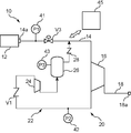
- the gas compression apparatus 10 includes a suction path 14 having an inflow side end 14 a to which a gas supply source 12 can be connected, and a compressor connected to the end of the suction path 14. 16 (hereinafter referred to as “main compressor 16”), a discharge path 18 connected to a discharge portion of the main compressor 16, a recovery portion 20, and a controller (control device) 45.
- the suction path 14 includes a suction path opening / closing valve V3 and a first sensor unit (pressure detector) 41.
- a non-illustrated pressure accumulator, dispenser, or the like can be connected to the outflow side end 18a of the discharge passage 18.
- the gas supply source 12 supplies, for example, hydrogen gas.
- This gas compression apparatus 10 can be used, for example, in a hydrogen station for filling hydrogen gas into a tank mounted on a fuel cell vehicle.
- the main compressor 16 is constituted by a reciprocating compressor in which a piston reciprocates in a cylinder. Since the piston slides in the cylinder, gas may leak from the compression chamber defined by the piston in the cylinder (hereinafter, the gas is referred to as “leak gas”).
- the recovery unit 20 is a system that recovers leak gas from the main compressor 16.
- the recovery unit 20 includes a recovery path 22, an auxiliary compressor 24 provided in the recovery path 22, a recovery tank 26 provided in the recovery path 22, a valve member V1, a valve member 28, a second sensor unit ( And a third sensor unit (pressure detector) 43.
- One end portion (upstream end portion in the leak gas flow direction) of the recovery path 22 is connected to a discharge portion for discharging the leak gas of the main compressor 16.
- the other end (downstream end) of the recovery path 22 is connected to the suction path 14.
- the auxiliary compressor 24 compresses leak gas.
- the auxiliary compressor 24 is constituted by a compressor smaller than the main compressor 16, specifically, a reciprocating compressor using a hypocycloid mechanism as an operation mechanism.
- the hypocycloid mechanism is connected to an outer ring gear (not shown), a planetary gear (not shown) provided with a crankshaft inserted therein and revolved in the outer ring gear, and connected to the planetary gear and disposed in the cylinder.
- Piston (not shown).
- the planetary gear rotates in the outer ring gear while meshing with the outer ring gear, whereby the rotation of the crankshaft is converted into the reciprocating motion of the piston.
- the recovery tank 26 is disposed on the discharge side (that is, the downstream side) of the auxiliary compressor 24 in the recovery path 22 and recovers the leak gas that has been pressurized by the auxiliary compressor 24.
- the valve member V1 is a check valve and is provided upstream of the auxiliary compressor 24.
- the valve member V ⁇ b> By providing the valve member V ⁇ b> 1, only the leak gas flow from the main compressor 16 to the auxiliary compressor 24 is allowed, and the backflow of leak gas from the auxiliary compressor 24 to the main compressor 16 is prevented.
- the valve member 28 is provided on the downstream side of the recovery tank 26. The valve member 28 allows only a leak gas flow from the recovery tank 26 to the suction path 14 and prevents the gas in the suction path 14 from flowing into the recovery tank 26.
- the suction path opening / closing valve V3 is located on the suction path 14 between the connection position with the recovery tank 26 (that is, the connection position between the downstream end of the recovery path 22 and the suction path 14) and the gas supply source 12.
- the suction passage opening / closing valve V3 is a normally open opening / closing valve.
- the first sensor unit 41 is a pressure sensor and is provided on the upstream side of the connection position with the recovery tank 26 in the suction passage 14, and gas supplied from the gas supply source 12 (hereinafter referred to as “supply gas”). Detect pressure.
- the second sensor unit 42 is a pressure sensor, and is provided in a portion of the recovery path 22 between the suction unit of the auxiliary compressor 24 and the discharge unit of the main compressor 16.
- the second sensor unit 42 detects the pressure of the leak gas from the main compressor 16.
- the third sensor unit 43 is a pressure sensor and is connected to the recovery tank 26 and detects the pressure of the gas in the recovery tank 26. Note that the third sensor unit 43 does not need to be directly connected to the recovery tank 26 as long as the pressure in the recovery tank 26 can be detected.
- the first sensor unit 41, the second sensor unit 42, and the third sensor unit 43 are connected to the controller 45 so as to be able to exchange signals.
- the controller 45 includes a storage unit, an arithmetic device, and the like, and is configured to perform a predetermined function by executing a program stored in the storage unit.
- the main compressor 16 When the gas compressor 10 is driven, the main compressor 16 is driven by the controller 45.
- the main compressor 16 compresses the supply gas supplied from the gas supply source 12 through the suction passage 14.
- the pressurized supply gas is discharged to the discharge path 18.
- the controller 45 receives the detected pressure value of the leak gas by the second sensor unit 42.
- the controller 45 performs control to drive the auxiliary compressor 45.
- the auxiliary compressor 24 is started and the leak gas is compressed (step S11). That is, the leakage gas is compressed by the auxiliary compressor 24.
- the auxiliary compressor 24 since the drive unit is stopped before the start of the leak gas recovery operation, the consumption and power consumption of parts of the auxiliary compressor 24 can be suppressed.
- the leak gas boosted by the auxiliary compressor 24 flows into the recovery tank 26 and is stored in the tank 26.
- the pressure of the leak gas in the recovery tank 26 is larger than the pressure in the suction path 14, the leak gas flows from the recovery tank 26 to the suction path 14. Therefore, the leak gas in the recovery tank 26 is returned to the suction path 14.
- the pressure of the gas immediately before the suction in the main compressor 16 is substantially the same as the larger one of the pressure of the supply gas in the gas supply source 12 or the pressure of the leak gas in the recovery tank 26. Therefore, the power consumption of the main compressor 16 can be reduced as compared with the case where the leak gas is not returned to the suction passage 14.
- the controller 45 monitors whether the pressure of the leak gas is excessive. That is, the pressure in the collection tank 26 is detected by the third sensor unit 43, and the controller 45 determines that the pressure P3 in the collection tank 26 detected by the third sensor unit 43 is equal to or higher than the threshold value P3t. Then (step S12), the controller 45 forcibly closes the suction passage opening / closing valve V3 (step S13).
- the pressure of the gas in the suction passage 14 (more precisely, the portion downstream of the suction passage opening / closing valve V3) becomes smaller than the pressure of the leak gas in the recovery tank 26.
- the leak gas in the recovery tank 26 can be easily returned to the suction path 14.
- the controller 45 compares the pressure P2 of the leak gas detected by the second sensor unit 42 with the threshold value P2t (step S14). When the detected pressure P2 is less than the threshold value P2t, the leakage gas compression operation by the auxiliary compressor 24 is stopped (step S15), and the leakage gas recovery operation is terminated. In the auxiliary compressor 24, the drive unit is stopped along with the stop of the compression work. Thereby, consumption of components and power consumption can be suppressed.
- step S11 If the detected pressure P2 is greater than or equal to the threshold value P2t, the compression work by the auxiliary compressor 24 is continued (step S11). At this time, if the pressure in the recovery tank 26 is higher than the pressure in the suction path 14, the leak gas recovered in the recovery tank 26 is returned to the suction path 14. On the other hand, if the pressure in the recovery tank 26 is lower than the pressure in the suction path 14, the leak gas is stored in the recovery tank 26 without being returned to the suction path 14. As described above, when the pressure P3 in the recovery tank 26 becomes equal to or higher than the threshold value P3t, the suction passage opening / closing valve V3 is forcibly closed (steps S12 and S13).
- the leak gas pressure P2 is compared with the threshold value P2t (step S14). If the detected pressure P2 is smaller than the threshold value P2t, the auxiliary compressor 24 compresses the leak gas. Stopped (step S15). Thus, in the gas compressor 10, the leak gas recovery operation by the gas compressor 10 is performed until the amount of leak gas flowing out from the main compressor 16 decreases.
- the recovery unit 20 since the recovery unit 20 returns the leaked gas leaked from the main compressor 16 to the suction side of the main compressor 16, the gas can be used without waste.
- the gas supply from the gas supply source 12 to the main compressor 16 is temporarily interrupted by closing the suction passage opening / closing valve V3, so that the leakage gas in the recovery tank 26 can be reliably removed. It can be returned to the suction path 14. As a result, the pressure of the leak gas in the recovery tank 26 is prevented from rising excessively. Further, since the auxiliary compressor 24 compresses the leak gas only when the pressure P2 of the leak gas between the auxiliary compressor 24 and the main compressor 16 is equal to or higher than the threshold value P2t, it is compared with the case where the leak gas is always compressed. Power consumption can be reduced.
- the auxiliary compressor 24 is constituted by a reciprocating compressor using a hypocycloid mechanism as an operation mechanism, the auxiliary compressor 24 can be easily downsized. In particular, in the case of a compressor using a hypocycloid mechanism as an operation mechanism, the driving sound can be reduced.
- the auxiliary compressor 24 is in a standby state before the start of the leak gas recovery operation, that is, the drive unit is operating without the compression unit substantially compressing the leak gas. May be. As a result, the auxiliary compressor 24 can quickly move to the compression operation.
- the auxiliary compressor 24 may be returned to the above-described standby state instead of stopping the drive unit. The same applies to the following second embodiment.
- a buffer tank 29 may be provided at a site on the recovery path 22 between the discharge part of the main compressor 16 and the suction part of the auxiliary compressor 24.
- the second sensor unit 42 is attached to the buffer tank 29.
- the buffer tank 29 temporarily stores leak gas from the main compressor 16. By providing the buffer tank 29, it is possible to prevent an abrupt increase in leak gas pressure at a portion on the recovery path 22 between the main compressor 16 and the auxiliary compressor 24. Also in the following second embodiment, a buffer tank 29 may be provided as in FIG.
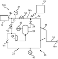
- FIG. 4 is a view showing a gas compression apparatus 10a according to the second embodiment.
- the suction path 14 includes a suction path body 14b and a branch path 30 that branches from the suction path body 14b.
- One end of the branch path 30 is connected to a portion of the recovery path 22 between the suction portion of the auxiliary compressor 24 and the discharge portion of the main compressor 16.
- the other end portion of the branch passage 30 is connected between the inflow side end portion 14a of the suction passage main body 14b and the suction passage opening / closing valve V3.
- the branch path 30 is provided with an on-off valve (branch path on-off valve V2).
- the branch path opening / closing valve V2 is normally closed.
- the other structure of the gas compression apparatus 10a is the same as that of the gas supply apparatus 10 of 1st Embodiment.
- the same reference numerals are given to the same components as those in the first embodiment.
- the operation of the main compressor 16 is the same as that of the first embodiment, and the leak gas recovery operation of the gas supply device 10a in the state where the branch path on-off valve V2 is closed is the same as that of the first embodiment.
- the pressure of the supply gas supplied from the gas supply source 12 may decrease. Therefore, in the gas compressor 10a, when the gas pressure in the suction passage 14 is less than a preset pressure (threshold value P1t), the auxiliary compressor 24 compresses the gas sucked into the main compressor 16. Use as a compressor.
- a preset pressure threshold value P1t
- the controller 45 determines that the pressure of the supply gas detected by the first sensor unit 41 has become less than the threshold value P1t, the controller 45 closes the supply passage opening / closing valve V3 and the branch passage opening / closing valve V2. Is controlled (step S21).
- the controller 45 performs control to activate the auxiliary compressor 24.
- the supply gas is sucked into the auxiliary compressor 24 via the branch path 30 and compressed (step S22).
- the auxiliary compressor 24 may shift from a standby state to a state in which compression work is performed.
- the pressurized supply gas is returned to the suction path 14 via the recovery tank 26 and sent to the main compressor 16.
- step S23 the pressure P1 of the supply gas detected by the first sensor unit 41 and the threshold value P1t are compared.
- the controller 45 maintains a state in which the supply path opening / closing valve V3 is closed and the branch path opening / closing valve V2 is opened. Therefore, the compression work by the auxiliary compressor 24 is continued (steps S21 and S22).
- step S23 the supply gas pressure P1 and the threshold value P1t are compared again (step S23), and when the pressure P1 becomes equal to or higher than the threshold value P1t, the controller 45 determines that the branch path on-off valve V2 Is closed and the supply passage opening / closing valve V3 is opened (step S24). As a result, the supply gas is supplied from the gas supply source 12 to the main compressor 16 only through the suction passage 14. Further, the compression work by the auxiliary compressor is stopped (step S25), and the pressure increase operation of the supply gas by the gas compression device 10a is completed.
- the gas compressor 10a when a leak gas is generated during the pressure increase operation of the supply gas, the leak gas is sucked into the auxiliary compressor 24 together with the supply gas.
- the gas pressurized by the auxiliary compressor 24 is sent to the main compressor 16 through the recovery tank 26.
- the branch path opening / closing valve V2 is opened.
- the auxiliary compressor 24 when the pressure P1 of the supply gas from the gas supply source 12 falls below the threshold value P1t, the auxiliary compressor 24 can be used for boosting the supply gas. That is, the auxiliary compressor 24 can be used as a part of the main compressor 16. As a result, the amount of pressure increase in the main compressor 16 is suppressed, and an excessive load on the main compressor 16 is prevented. As a result, the power consumption of the main compressor 16 can also be reduced. Moreover, the upper limit of the compression ratio of the main compressor 16 can be suppressed, and the main compressor 16 can be downsized.
- the controller 45 may block the branch on-off valve V2. Good. As a result, the leak gas is preferentially sucked into the auxiliary compressor 24. The leak gas boosted by the auxiliary compressor 24 is returned to the suction passage 14 via the recovery tank 26.
- the auxiliary compressor 24 is configured by a reciprocating compressor using a hypocycloid mechanism as an operation mechanism, but is not limited thereto.
- the auxiliary compressor 24 may be configured by a reciprocating compressor using a reciprocating motor or a linear motor as a drive source.
- an on-off valve may be used as the valve member 28 instead of the check valve.
- the controller 45 performs opening / closing control of the opening / closing valve based on the detection value of the third sensor unit 43 and the detection value of the first sensor unit 41.
- the valve member 28 may be configured by a check valve and an on-off valve.
- an on-off valve may be used as the valve member V1 instead of the check valve, and the valve member V1 may be configured by the check valve and the on-off valve.
- the first sensor unit 41 may be a flow rate sensor that detects the flow rate of the supply gas.
- the second sensor unit 42 may be a flow rate sensor that detects the flow rate of the leak gas.
- the auxiliary compressor 24 is not necessarily separate from the main compressor 16, and a part of the main compressor 16 may also function as the auxiliary compressor 24.
- the comparison between the leak gas pressure P2 and the threshold value P2t may be performed continuously.
- the comparison between the supply gas pressure P1 and the threshold value P1t may be performed continuously.
- the gas compressor of the embodiment includes a compressor that compresses gas supplied from a gas supply source through a suction path, and a recovery unit that recovers leaked gas leaked from the compressor.
- the recovery unit includes an auxiliary compressor that compresses the leaked gas leaked from the compressor, and a recovery tank that recovers the leaked gas boosted by the auxiliary compressor, and the leaked gas recovered in the recovery tank is It is configured to be able to be delivered to the suction path.
- the leak gas recovery unit since the leak gas recovery unit returns the leak gas leaked from the compressor to the suction side of the compressor, the gas can be used without waste.
- the gas compression device may further include a control device and a pressure detector that detects a pressure of leak gas between the auxiliary compressor and the compressor.
- the control device controls the auxiliary compressor so that leak gas is compressed by the auxiliary compressor when the pressure value detected by the first pressure detector is equal to or greater than a threshold value. Also good.
- the power consumption of the auxiliary compressor can be reduced.
- the gas compression device may further include a control device and a pressure detector that detects the pressure of the gas of the gas supply source.
- the suction path may include a branch path connected to the suction side of the auxiliary compressor.
- the control device supplies the gas from the gas supply source to the auxiliary compressor through the branch path and supplies the gas to the auxiliary compressor. You may perform control which an auxiliary compressor compresses.
- the gas pressure of the gas supply source when the gas pressure of the gas supply source is reduced, the gas is introduced into the auxiliary compressor, and the gas is compressed by the auxiliary compressor. If the compressed gas is higher than the gas pressure in the suction passage, it is returned to the suction passage. That is, the auxiliary compressor can be used for boosting the gas supplied from the gas supply source. Therefore, even when the pressure of the gas from the gas supply source is reduced, an excessive load on the compressor can be prevented. Further, the power consumption of the compressor can be reduced.
- the gas compression device includes a control device, a pressure detector for detecting the pressure of the recovery tank, and a suction path provided between the connection part of the recovery tank and the gas supply source in the suction path. And an on-off valve.
- the control device may perform control to close the suction path opening / closing valve when the pressure value detected by the pressure detector is equal to or greater than a threshold value.
- the gas supply from the gas supply source is temporarily shut off by closing the suction passage opening / closing valve, so that the leak gas in the recovery tank can be reliably returned to the suction passage. This prevents the pressure in the recovery tank from rising excessively.
- the gas compressor may further include a buffer tank that temporarily stores leak gas between the compressor and the suction portion of the auxiliary compressor. In this aspect, even if a gas leak occurs from the compressor, it is possible to prevent a steep pressure increase between the compressor and the auxiliary compressor.
- the auxiliary compressor may be any one of a reciprocating compressor using a hypocycloid mechanism as an operating mechanism, a reciprocating compressor using a reciprocating motor or a linear motor as a driving source.
- the auxiliary compressor when these compressors are used, the auxiliary compressor can be reduced in size.
- the driving sound in the case of a compressor using a hypocycloid mechanism as an operation mechanism, the driving sound can be reduced.
- the method for operating the gas compressor wherein the auxiliary compressor is operated when a pressure value of a leak gas between the auxiliary compressor and the compressor becomes a threshold value or more. Compress leak gas.
- the operation method of the gas compression apparatus is the gas of the gas supply source.
- the auxiliary compressor may compress the gas supplied from the branch path and return it to the suction path.
- the gas compressor further includes a suction passage opening / closing valve provided between the connection position of the recovery tank and the gas supply source in the suction passage, the operation of the gas compressor is performed.
- the suction path on-off valve may be closed when leaking gas from the recovery tank to the suction path.
- the gas supplied from the gas supply source can be used without waste.
Landscapes
- Engineering & Computer Science (AREA)
- Mechanical Engineering (AREA)
- General Engineering & Computer Science (AREA)
- Control Of Positive-Displacement Pumps (AREA)
- Compressor (AREA)
- Compressors, Vaccum Pumps And Other Relevant Systems (AREA)
Priority Applications (5)
| Application Number | Priority Date | Filing Date | Title |
|---|---|---|---|
| DK15812058.4T DK3163081T3 (en) | 2014-06-27 | 2015-06-04 | GAS COMPRESSOR UNIT. |
| KR1020167035927A KR101888292B1 (ko) | 2014-06-27 | 2015-06-04 | 가스 압축 장치 |
| US15/320,674 US10247179B2 (en) | 2014-06-27 | 2015-06-04 | Gas compression device |
| CN201580034222.8A CN106460822B (zh) | 2014-06-27 | 2015-06-04 | 气体压缩装置 |
| EP15812058.4A EP3163081B1 (de) | 2014-06-27 | 2015-06-04 | Gaskompressionsvorrichtung |
Applications Claiming Priority (2)
| Application Number | Priority Date | Filing Date | Title |
|---|---|---|---|
| JP2014133006A JP6276120B2 (ja) | 2014-06-27 | 2014-06-27 | ガス圧縮装置 |
| JP2014-133006 | 2014-06-27 |
Publications (1)
| Publication Number | Publication Date |
|---|---|
| WO2015198822A1 true WO2015198822A1 (ja) | 2015-12-30 |
Family
ID=54937918
Family Applications (1)
| Application Number | Title | Priority Date | Filing Date |
|---|---|---|---|
| PCT/JP2015/066165 WO2015198822A1 (ja) | 2014-06-27 | 2015-06-04 | ガス圧縮装置 |
Country Status (7)
| Country | Link |
|---|---|
| US (1) | US10247179B2 (de) |
| EP (1) | EP3163081B1 (de) |
| JP (1) | JP6276120B2 (de) |
| KR (1) | KR101888292B1 (de) |
| CN (1) | CN106460822B (de) |
| DK (1) | DK3163081T3 (de) |
| WO (1) | WO2015198822A1 (de) |
Cited By (3)
| Publication number | Priority date | Publication date | Assignee | Title |
|---|---|---|---|---|
| CN107202011A (zh) * | 2016-03-16 | 2017-09-26 | 株式会社日立产机系统 | 多级压缩机 |
| JP2019183993A (ja) * | 2018-04-12 | 2019-10-24 | 株式会社神戸製鋼所 | ガス供給装置及びその停止制御方法 |
| WO2023122501A1 (en) * | 2021-12-22 | 2023-06-29 | Uop Llc | Processes and apparatuses for operating a gas compressor |
Families Citing this family (8)
| Publication number | Priority date | Publication date | Assignee | Title |
|---|---|---|---|---|
| JP6637318B2 (ja) * | 2016-02-02 | 2020-01-29 | 株式会社神戸製鋼所 | ガス供給装置 |
| CN108730760B (zh) * | 2017-04-13 | 2022-02-25 | 全球能源互联网研究院 | 一种储氢罐充放氢性能检测系统 |
| US11761443B2 (en) * | 2018-07-10 | 2023-09-19 | Hitachi Industrial Equipment Systems Co., Ltd. | Compressor and monitoring system |
| CN113803637B (zh) * | 2020-06-11 | 2023-07-04 | 中国石油化工股份有限公司 | 高压气体压力控制系统 |
| US11359767B2 (en) * | 2020-06-28 | 2022-06-14 | Marlin Gas Services, Llc | Gas control system |
| US11629887B2 (en) | 2020-06-28 | 2023-04-18 | Marlin Gas Services, Llc | Gas control system |
| US11629859B2 (en) | 2020-06-28 | 2023-04-18 | Marlin Gas Services, Llc | Gas control system |
| EP4279741A1 (de) | 2022-05-18 | 2023-11-22 | Burckhardt Compression AG | Gasverdichtungssystem und verfahren zur rückgewinnung von wasserstoff |
Citations (7)
| Publication number | Priority date | Publication date | Assignee | Title |
|---|---|---|---|---|
| JPS62118075A (ja) * | 1985-11-15 | 1987-05-29 | Hitachi Ltd | ガス圧縮装置 |
| JPH0311190A (ja) * | 1989-06-08 | 1991-01-18 | Hokuetsu Kogyo Co Ltd | コンプレッサの容量制御切換方法 |
| JP2005069109A (ja) * | 2003-08-25 | 2005-03-17 | Tokyo Electric Power Co Inc:The | バッファタンクを備えた燃料ガス供給装置 |
| JP2009209905A (ja) * | 2008-03-06 | 2009-09-17 | Kobe Steel Ltd | 往復動圧縮機のガス漏洩防止システム |
| JP2010513779A (ja) * | 2006-12-18 | 2010-04-30 | アンドレアス ホーファー ホーホドルックテヒニーク ゲゼルシャフト ミット ベシュレンクテル ハフツング | 流体機械 |
| US20120006411A1 (en) * | 2009-12-23 | 2012-01-12 | Solar Turbines Inc. | Fluid compression system |
| JP5378624B1 (ja) * | 2013-07-03 | 2013-12-25 | 東京瓦斯株式会社 | 高圧水素製造システム、および、高圧水素製造システムの運転方法 |
Family Cites Families (10)
| Publication number | Priority date | Publication date | Assignee | Title |
|---|---|---|---|---|
| US4273514A (en) * | 1978-10-06 | 1981-06-16 | Ferakarn Limited | Waste gas recovery systems |
| JP2005351255A (ja) * | 2004-06-10 | 2005-12-22 | Kaken Geneqs:Kk | レシプロ圧縮機 |
| JP4754890B2 (ja) * | 2005-07-07 | 2011-08-24 | 伊藤工機株式会社 | 据置貯槽のガス回収 |
| JP4611924B2 (ja) * | 2006-03-29 | 2011-01-12 | 株式会社日立プラントテクノロジー | 水素圧縮機システム |
| JP2009009905A (ja) * | 2007-06-29 | 2009-01-15 | Sumitomo Electric Ind Ltd | 薄膜リチウム二次電池およびその製造方法 |
| JP5439161B2 (ja) | 2009-12-24 | 2014-03-12 | 株式会社日立製作所 | 水素ガスリーク監視システム |
| JP5776793B2 (ja) * | 2011-12-09 | 2015-09-09 | 株式会社村田製作所 | 気体制御装置 |
| CN202746257U (zh) * | 2012-07-04 | 2013-02-20 | 中国石油天然气股份有限公司 | 离心式压缩机的干气密封泄漏气的回收系统 |
| RU2636288C2 (ru) * | 2013-05-22 | 2017-11-21 | Грундфос Холдинг А/С | Многоступенчатый самовсасывающий центробежный насосный агрегат |
| JP6279340B2 (ja) * | 2014-02-14 | 2018-02-14 | 株式会社神戸製鋼所 | ガス供給装置、水素ステーション及びガス供給方法 |
-
2014
- 2014-06-27 JP JP2014133006A patent/JP6276120B2/ja active Active
-
2015
- 2015-06-04 CN CN201580034222.8A patent/CN106460822B/zh active Active
- 2015-06-04 KR KR1020167035927A patent/KR101888292B1/ko active IP Right Grant
- 2015-06-04 DK DK15812058.4T patent/DK3163081T3/en active
- 2015-06-04 WO PCT/JP2015/066165 patent/WO2015198822A1/ja active Application Filing
- 2015-06-04 US US15/320,674 patent/US10247179B2/en active Active
- 2015-06-04 EP EP15812058.4A patent/EP3163081B1/de active Active
Patent Citations (7)
| Publication number | Priority date | Publication date | Assignee | Title |
|---|---|---|---|---|
| JPS62118075A (ja) * | 1985-11-15 | 1987-05-29 | Hitachi Ltd | ガス圧縮装置 |
| JPH0311190A (ja) * | 1989-06-08 | 1991-01-18 | Hokuetsu Kogyo Co Ltd | コンプレッサの容量制御切換方法 |
| JP2005069109A (ja) * | 2003-08-25 | 2005-03-17 | Tokyo Electric Power Co Inc:The | バッファタンクを備えた燃料ガス供給装置 |
| JP2010513779A (ja) * | 2006-12-18 | 2010-04-30 | アンドレアス ホーファー ホーホドルックテヒニーク ゲゼルシャフト ミット ベシュレンクテル ハフツング | 流体機械 |
| JP2009209905A (ja) * | 2008-03-06 | 2009-09-17 | Kobe Steel Ltd | 往復動圧縮機のガス漏洩防止システム |
| US20120006411A1 (en) * | 2009-12-23 | 2012-01-12 | Solar Turbines Inc. | Fluid compression system |
| JP5378624B1 (ja) * | 2013-07-03 | 2013-12-25 | 東京瓦斯株式会社 | 高圧水素製造システム、および、高圧水素製造システムの運転方法 |
Cited By (4)
| Publication number | Priority date | Publication date | Assignee | Title |
|---|---|---|---|---|
| CN107202011A (zh) * | 2016-03-16 | 2017-09-26 | 株式会社日立产机系统 | 多级压缩机 |
| JP2019183993A (ja) * | 2018-04-12 | 2019-10-24 | 株式会社神戸製鋼所 | ガス供給装置及びその停止制御方法 |
| JP7025272B2 (ja) | 2018-04-12 | 2022-02-24 | 株式会社神戸製鋼所 | ガス供給装置及びその停止制御方法 |
| WO2023122501A1 (en) * | 2021-12-22 | 2023-06-29 | Uop Llc | Processes and apparatuses for operating a gas compressor |
Also Published As
| Publication number | Publication date |
|---|---|
| CN106460822A (zh) | 2017-02-22 |
| EP3163081B1 (de) | 2018-12-12 |
| JP6276120B2 (ja) | 2018-02-07 |
| EP3163081A1 (de) | 2017-05-03 |
| KR101888292B1 (ko) | 2018-08-13 |
| CN106460822B (zh) | 2018-09-04 |
| KR20170010821A (ko) | 2017-02-01 |
| DK3163081T3 (en) | 2019-04-08 |
| JP2016011618A (ja) | 2016-01-21 |
| US10247179B2 (en) | 2019-04-02 |
| EP3163081A4 (de) | 2018-02-14 |
| US20170146001A1 (en) | 2017-05-25 |
Similar Documents
| Publication | Publication Date | Title |
|---|---|---|
| WO2015198822A1 (ja) | ガス圧縮装置 | |
| KR101693083B1 (ko) | 가스 충전 장치 및 가스 충전 방법 | |
| RU2008130362A (ru) | Гидростатический привод | |
| JP2007263245A (ja) | 水素圧縮機システム | |
| US20160230786A1 (en) | Hydraulic pressure generation unit with pneumatic actuation | |
| JP5807227B2 (ja) | エネルギー回収装置およびエネルギー回収方法 | |
| JP6375415B2 (ja) | 高圧洗浄装置及び高圧洗浄車 | |
| JP2016070133A (ja) | エアコンプレッサ | |
| US11466705B2 (en) | Hydraulic unit with combined pneumatic/servomotor action and related use | |
| JP2004239392A (ja) | 油圧装置 | |
| EP2889555B1 (de) | Verdichter mit unter Druck stehendem Gehäuse | |
| JP6249671B2 (ja) | インバータ駆動圧縮機の運転制御方法及びインバータ駆動圧縮機 | |
| JP2011099348A (ja) | 空気圧縮機 | |
| JP5598063B2 (ja) | 空気圧縮機 | |
| JP2008248846A (ja) | ガス昇圧圧縮装置 | |
| JP6157871B2 (ja) | 高圧洗浄装置及び高圧洗浄車 | |
| JP6763684B2 (ja) | ブースタ圧縮機 | |
| JP2011179457A (ja) | 油圧ポンプの駆動制御装置 | |
| KR101491291B1 (ko) | 차량의 isg 장치 | |
| JP2007247802A (ja) | 圧力制御性に優れる油圧制御回路 | |
| KR101745931B1 (ko) | 오일 배출 개선용 컴프레서 | |
| JP2021124090A (ja) | 圧縮機 | |
| KR20180003278A (ko) | 폐기 유압을 이용한 공압 구동장치 | |
| JP2023162010A (ja) | インバータ駆動圧縮機の運転制御方法及びインバータ駆動圧縮機 | |
| CN105855755A (zh) | 一种内焊机气动系统 |
Legal Events
| Date | Code | Title | Description |
|---|---|---|---|
| 121 | Ep: the epo has been informed by wipo that ep was designated in this application |
Ref document number: 15812058 Country of ref document: EP Kind code of ref document: A1 |
|
| REEP | Request for entry into the european phase |
Ref document number: 2015812058 Country of ref document: EP |
|
| WWE | Wipo information: entry into national phase |
Ref document number: 2015812058 Country of ref document: EP |
|
| WWE | Wipo information: entry into national phase |
Ref document number: 15320674 Country of ref document: US |
|
| WWE | Wipo information: entry into national phase |
Ref document number: 1020167035927 Country of ref document: KR |
|
| NENP | Non-entry into the national phase |
Ref country code: DE |